WO2023032072A1 - Compresseur - Google Patents
Compresseur Download PDFInfo
- Publication number
- WO2023032072A1 WO2023032072A1 PCT/JP2021/032110 JP2021032110W WO2023032072A1 WO 2023032072 A1 WO2023032072 A1 WO 2023032072A1 JP 2021032110 W JP2021032110 W JP 2021032110W WO 2023032072 A1 WO2023032072 A1 WO 2023032072A1
- Authority
- WO
- WIPO (PCT)
- Prior art keywords
- refrigerant
- compressor
- blade
- nitride layer
- tin
- Prior art date
- Legal status (The legal status is an assumption and is not a legal conclusion. Google has not performed a legal analysis and makes no representation as to the accuracy of the status listed.)
- Ceased
Links
Images


Classifications
-
- F—MECHANICAL ENGINEERING; LIGHTING; HEATING; WEAPONS; BLASTING
- F25—REFRIGERATION OR COOLING; COMBINED HEATING AND REFRIGERATION SYSTEMS; HEAT PUMP SYSTEMS; MANUFACTURE OR STORAGE OF ICE; LIQUEFACTION SOLIDIFICATION OF GASES
- F25B—REFRIGERATION MACHINES, PLANTS OR SYSTEMS; COMBINED HEATING AND REFRIGERATION SYSTEMS; HEAT PUMP SYSTEMS
- F25B31/00—Compressor arrangements
- F25B31/02—Compressor arrangements of motor-compressor units
- F25B31/026—Compressor arrangements of motor-compressor units with compressor of rotary type
-
- F—MECHANICAL ENGINEERING; LIGHTING; HEATING; WEAPONS; BLASTING
- F04—POSITIVE - DISPLACEMENT MACHINES FOR LIQUIDS; PUMPS FOR LIQUIDS OR ELASTIC FLUIDS
- F04C—ROTARY-PISTON, OR OSCILLATING-PISTON, POSITIVE-DISPLACEMENT MACHINES FOR LIQUIDS; ROTARY-PISTON, OR OSCILLATING-PISTON, POSITIVE-DISPLACEMENT PUMPS
- F04C18/00—Rotary-piston pumps specially adapted for elastic fluids
- F04C18/30—Rotary-piston pumps specially adapted for elastic fluids having the characteristics covered by two or more of groups F04C18/02, F04C18/08, F04C18/22, F04C18/24, F04C18/48, or having the characteristics covered by one of these groups together with some other type of movement between co-operating members
- F04C18/34—Rotary-piston pumps specially adapted for elastic fluids having the characteristics covered by two or more of groups F04C18/02, F04C18/08, F04C18/22, F04C18/24, F04C18/48, or having the characteristics covered by one of these groups together with some other type of movement between co-operating members having the movement defined in group F04C18/08 or F04C18/22 and relative reciprocation between the co-operating members
- F04C18/356—Rotary-piston pumps specially adapted for elastic fluids having the characteristics covered by two or more of groups F04C18/02, F04C18/08, F04C18/22, F04C18/24, F04C18/48, or having the characteristics covered by one of these groups together with some other type of movement between co-operating members having the movement defined in group F04C18/08 or F04C18/22 and relative reciprocation between the co-operating members with vanes reciprocating with respect to the outer member
-
- F—MECHANICAL ENGINEERING; LIGHTING; HEATING; WEAPONS; BLASTING
- F04—POSITIVE - DISPLACEMENT MACHINES FOR LIQUIDS; PUMPS FOR LIQUIDS OR ELASTIC FLUIDS
- F04C—ROTARY-PISTON, OR OSCILLATING-PISTON, POSITIVE-DISPLACEMENT MACHINES FOR LIQUIDS; ROTARY-PISTON, OR OSCILLATING-PISTON, POSITIVE-DISPLACEMENT PUMPS
- F04C29/00—Component parts, details or accessories of pumps or pumping installations, not provided for in groups F04C18/00 - F04C28/00
-
- F—MECHANICAL ENGINEERING; LIGHTING; HEATING; WEAPONS; BLASTING
- F04—POSITIVE - DISPLACEMENT MACHINES FOR LIQUIDS; PUMPS FOR LIQUIDS OR ELASTIC FLUIDS
- F04B—POSITIVE-DISPLACEMENT MACHINES FOR LIQUIDS; PUMPS
- F04B39/00—Component parts, details, or accessories, of pumps or pumping systems specially adapted for elastic fluids, not otherwise provided for in, or of interest apart from, groups F04B25/00 - F04B37/00
-
- F—MECHANICAL ENGINEERING; LIGHTING; HEATING; WEAPONS; BLASTING
- F04—POSITIVE - DISPLACEMENT MACHINES FOR LIQUIDS; PUMPS FOR LIQUIDS OR ELASTIC FLUIDS
- F04C—ROTARY-PISTON, OR OSCILLATING-PISTON, POSITIVE-DISPLACEMENT MACHINES FOR LIQUIDS; ROTARY-PISTON, OR OSCILLATING-PISTON, POSITIVE-DISPLACEMENT PUMPS
- F04C2210/00—Fluid
- F04C2210/26—Refrigerants with particular properties, e.g. HFC-134a
- F04C2210/261—Carbon dioxide (CO2)
-
- F—MECHANICAL ENGINEERING; LIGHTING; HEATING; WEAPONS; BLASTING
- F04—POSITIVE - DISPLACEMENT MACHINES FOR LIQUIDS; PUMPS FOR LIQUIDS OR ELASTIC FLUIDS
- F04C—ROTARY-PISTON, OR OSCILLATING-PISTON, POSITIVE-DISPLACEMENT MACHINES FOR LIQUIDS; ROTARY-PISTON, OR OSCILLATING-PISTON, POSITIVE-DISPLACEMENT PUMPS
- F04C2230/00—Manufacture
- F04C2230/90—Improving properties of machine parts
- F04C2230/91—Coating
-
- F—MECHANICAL ENGINEERING; LIGHTING; HEATING; WEAPONS; BLASTING
- F04—POSITIVE - DISPLACEMENT MACHINES FOR LIQUIDS; PUMPS FOR LIQUIDS OR ELASTIC FLUIDS
- F04C—ROTARY-PISTON, OR OSCILLATING-PISTON, POSITIVE-DISPLACEMENT MACHINES FOR LIQUIDS; ROTARY-PISTON, OR OSCILLATING-PISTON, POSITIVE-DISPLACEMENT PUMPS
- F04C23/00—Combinations of two or more pumps, each being of rotary-piston or oscillating-piston type, specially adapted for elastic fluids; Pumping installations specially adapted for elastic fluids; Multi-stage pumps specially adapted for elastic fluids
- F04C23/008—Hermetic pumps
-
- F—MECHANICAL ENGINEERING; LIGHTING; HEATING; WEAPONS; BLASTING
- F05—INDEXING SCHEMES RELATING TO ENGINES OR PUMPS IN VARIOUS SUBCLASSES OF CLASSES F01-F04
- F05C—INDEXING SCHEME RELATING TO MATERIALS, MATERIAL PROPERTIES OR MATERIAL CHARACTERISTICS FOR MACHINES, ENGINES OR PUMPS OTHER THAN NON-POSITIVE-DISPLACEMENT MACHINES OR ENGINES
- F05C2201/00—Metals
- F05C2201/04—Heavy metals
- F05C2201/0403—Refractory metals, e.g. V, W
- F05C2201/0406—Chromium
-
- F—MECHANICAL ENGINEERING; LIGHTING; HEATING; WEAPONS; BLASTING
- F05—INDEXING SCHEMES RELATING TO ENGINES OR PUMPS IN VARIOUS SUBCLASSES OF CLASSES F01-F04
- F05C—INDEXING SCHEME RELATING TO MATERIALS, MATERIAL PROPERTIES OR MATERIAL CHARACTERISTICS FOR MACHINES, ENGINES OR PUMPS OTHER THAN NON-POSITIVE-DISPLACEMENT MACHINES OR ENGINES
- F05C2201/00—Metals
- F05C2201/04—Heavy metals
- F05C2201/0403—Refractory metals, e.g. V, W
- F05C2201/0412—Titanium
-
- F—MECHANICAL ENGINEERING; LIGHTING; HEATING; WEAPONS; BLASTING
- F05—INDEXING SCHEMES RELATING TO ENGINES OR PUMPS IN VARIOUS SUBCLASSES OF CLASSES F01-F04
- F05C—INDEXING SCHEME RELATING TO MATERIALS, MATERIAL PROPERTIES OR MATERIAL CHARACTERISTICS FOR MACHINES, ENGINES OR PUMPS OTHER THAN NON-POSITIVE-DISPLACEMENT MACHINES OR ENGINES
- F05C2203/00—Non-metallic inorganic materials
- F05C2203/08—Ceramics; Oxides
- F05C2203/0804—Non-oxide ceramics
- F05C2203/0813—Carbides
-
- F—MECHANICAL ENGINEERING; LIGHTING; HEATING; WEAPONS; BLASTING
- F05—INDEXING SCHEMES RELATING TO ENGINES OR PUMPS IN VARIOUS SUBCLASSES OF CLASSES F01-F04
- F05C—INDEXING SCHEME RELATING TO MATERIALS, MATERIAL PROPERTIES OR MATERIAL CHARACTERISTICS FOR MACHINES, ENGINES OR PUMPS OTHER THAN NON-POSITIVE-DISPLACEMENT MACHINES OR ENGINES
- F05C2203/00—Non-metallic inorganic materials
- F05C2203/08—Ceramics; Oxides
- F05C2203/0804—Non-oxide ceramics
- F05C2203/083—Nitrides
-
- F—MECHANICAL ENGINEERING; LIGHTING; HEATING; WEAPONS; BLASTING
- F05—INDEXING SCHEMES RELATING TO ENGINES OR PUMPS IN VARIOUS SUBCLASSES OF CLASSES F01-F04
- F05C—INDEXING SCHEME RELATING TO MATERIALS, MATERIAL PROPERTIES OR MATERIAL CHARACTERISTICS FOR MACHINES, ENGINES OR PUMPS OTHER THAN NON-POSITIVE-DISPLACEMENT MACHINES OR ENGINES
- F05C2203/00—Non-metallic inorganic materials
- F05C2203/08—Ceramics; Oxides
- F05C2203/0804—Non-oxide ceramics
- F05C2203/083—Nitrides
- F05C2203/0847—Nitrides of titanium
Definitions
- the present invention relates to compressors.
- compressors such as refrigerant compressors are used that have a compression mechanism that sucks in and discharges refrigerant, which is a working fluid.
- refrigerant which is a working fluid.
- heat is likely to be generated in a sliding portion such as the tip surface of a blade of a compressor and the outer peripheral surface of a roller, and the refrigerant may be thermally decomposed. Products from thermal decomposition of the refrigerant can lead to compressor failure.
- Patent Literature 1 discloses adding an antioxidant or the like to refrigerating machine oil in order to suppress the generation of reaction products of the refrigerant.
- Patent Document 1 only discusses refrigerating machine oil for suppressing thermal decomposition of the refrigerant, and does not discuss the configuration of sliding parts for reducing heat generation due to sliding of the compressor. .
- the problem to be solved by the present invention is to provide a compressor that can reduce heat generation due to sliding.
- a compressor has a compression mechanism that compresses a refrigerant in a closed container, the compression mechanism containing Cr, comprising a first member and a second member that slide relative to each other, and a first A chromium layer and a nitride layer containing CrN and TiN are formed in this order on the base material surface of the member (1), and carbides are deposited on the surface of the second member.
- the compressor of the embodiment has a compression mechanism that compresses the refrigerant inside the closed container.
- the compression mechanism includes chromium and includes first and second members that slide relative to each other.
- a chromium layer and a nitride layer containing chromium nitride and titanium nitride are formed in this order on the base material surface of the first member, and carbide is precipitated on the surface of the second member.
- the compressor of the embodiment may be a compressor having these characteristics, and other than these characteristics, known aspects can be adopted without limitation.
- the refrigeration cycle device 1 includes a compressor 2, a condenser 3 as a radiator connected to the compressor 2, an expansion device 4 connected to the condenser 3, and an expansion device 4. and an evaporator 5 as a heat absorber connected between the compressor 2 .
- the compressor 2 is a so-called rotary compressor that takes in gaseous refrigerant and compresses it into a high-temperature, high-pressure refrigerant.
- the compressor 2 is not limited to the rotary type, and may be a scroll type, reciprocating type, swash plate type, or other type of compressor.
- the condenser 3 radiates heat from the high-temperature, high-pressure gaseous refrigerant sent from the compressor 2 to convert it into a high-pressure liquid refrigerant.
- the expansion device 4 reduces the pressure of the high-pressure liquid refrigerant sent from the condenser 3 to a low-temperature, low-pressure liquid refrigerant.
- the evaporator 5 evaporates the low-temperature, low-pressure liquid refrigerant fed from the expansion device 4 and converts the low-temperature, low-pressure liquid refrigerant into a low-pressure gaseous refrigerant.
- the evaporator 5 when the low-pressure liquid refrigerant is vaporized, heat of vaporization is taken from the surroundings, and the surroundings are cooled.
- the low-pressure gaseous refrigerant that has passed through the evaporator 5 is taken into the compressor 2 .
- the refrigerant circulates while undergoing a phase change between gas refrigerant and liquid refrigerant.
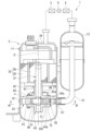
- the compressor 2 includes a compressor body 11 and an accumulator 12 .
- the accumulator 12 is a so-called gas-liquid separator.
- the accumulator 12 is connected to the compressor body 11 through a suction pipe 21 .
- the accumulator 12 is connected to the evaporator 5 and supplies only gaseous refrigerant to the compressor body 11 among the refrigerant vaporized by the evaporator 5 and the liquid refrigerant that is not vaporized by the evaporator 5 .
- the compressor main body 11 includes a rotating shaft 31, an electric motor section 32, a compression mechanism section 33, and a sealed container 34 that houses the rotating shaft 31, the electric motor section 32, and the compression mechanism section 33.
- the sealed container 34 is formed in a cylindrical shape, and both ends in the direction of the axis O are closed. Refrigerant oil J is stored in the sealed container 34 . A portion of the compression mechanism 33 is immersed in the refrigerator oil J. As shown in FIG.
- the rotating shaft 31 is arranged coaxially along the axis O of the closed container 34 .
- the direction along the axis O is simply referred to as the axial direction
- the direction orthogonal to the axial direction is referred to as the radial direction
- the direction around the axis O is referred to as the circumferential direction.
- the electric motor section 32 is arranged on the first side in the axial direction within the sealed container 34 .
- the compression mechanism part 33 is arranged on the second side in the axial direction inside the sealed container 34 .
- the electric motor section 32 side (first side) along the axial direction is the upper side
- the compression mechanism section 33 side (the second side) is the lower side.
- the electric motor unit 32 is a so-called inner rotor type DC brushless motor.
- the electric motor section 32 includes a stator 35 and a rotor 36 .
- the stator 35 is fixed to the inner wall surface of the sealed container 34 by shrink fitting or the like.
- the rotor 36 is fixed to the upper portion of the rotating shaft 31 while being radially spaced inside the stator 35 .
- the compression mechanism portion 33 includes a cylindrical cylinder 41 through which the rotating shaft 31 passes, a main bearing 42 and a sub-bearing 43 that close both axial end openings of the cylinder 41 and rotatably support the rotating shaft 31. , is equipped with A space formed by the cylinder 41 , the main bearing 42 and the sub-bearing 43 constitutes a cylinder chamber 46 .
- An eccentric portion 51 that is radially eccentric with respect to the axis O is formed in a portion of the rotating shaft 31 that is positioned within the cylinder chamber 46 .
- a roller 53 is fitted around the eccentric portion 51 .
- the roller 53 is configured to be eccentrically rotatable with respect to the axis O while the outer peripheral surface 53a is in sliding contact with the inner peripheral surface 41a of the cylinder 41 via the refrigerator oil film as the rotary shaft 31 rotates.
- a part of the cylinder 41 in the circumferential direction is formed with a blade groove 54 that is recessed radially outward.
- the blade groove 54 is formed over the entire axial direction (height direction) of the cylinder 41 .
- the blade groove 54 communicates with the inside of the closed container 34 at its radially outer end.
- a blade 55 is provided in the blade groove 54 .
- the blade 55 is configured to be slidable in the radial direction with respect to the cylinder 41 .
- the blade 55 is biased radially inwardly by biasing means 57 at its rear surface 55 b , which is a radially outer end face.
- the blade 55 has a radial inner end surface 55 a in contact with the outer peripheral surface 53 a of the roller 53 in the cylinder chamber 46 .
- the blade 55 is configured to move forward and backward in the cylinder chamber 46 as the roller 53 rotates eccentrically.
- the roller 53 and the blade 55 divide the cylinder chamber 46 into a suction chamber 46a and a compression chamber 46b. Note that in a plan view in the axial direction, the tip surface 55a of the blade 55 has an arcuate shape that protrudes inward in the radial direction.
- Refrigerant oil J is interposed between the blade 55 and the inner surfaces 54a and 54b of the blade groove 54, between the blade 55 and the lower surface 42a of the main bearing 42, and between the blade 55 and the upper surface 43a of the sub-bearing 43. .
- a suction hole penetrating the cylinder 41 in the radial direction is provided in a portion of the cylinder 41 located forward (left side of the blade groove 54 in FIG. 2) in the direction of rotation of the roller 53 with respect to the blade groove 54 (see the arrow in FIG. 2). 56 are formed.
- a radially outer end of the suction hole 56 is connected to the suction pipe 21 (see FIG. 1).
- a radial inner end of the suction hole 56 opens into the suction chamber 46 a of the cylinder chamber 46 .
- a discharge groove 58 is formed in a portion of the cylinder 41 located on the front side of the blade groove 54 along the rotation direction of the roller 53 (on the right side of the blade groove 54 in FIG. 2).
- the discharge groove 58 is formed in a semicircular shape when viewed from above in the axial direction.
- the discharge groove 58 is open at least on the upper surface of the cylinder 41 .
- the main bearing 42 closes the upper end opening of the cylinder 41 .
- the main bearing 42 rotatably supports a portion of the rotating shaft 31 located above the cylinder 41 .
- the main bearing 42 includes a cylindrical portion 61 through which the rotating shaft 31 is inserted, and a flange portion 62 projecting radially outward from the lower end portion of the cylindrical portion 61 .
- a part of the flange portion 62 in the circumferential direction is formed with a discharge hole 64 (see FIG. 2) that penetrates the flange portion 62 in the axial direction.
- the discharge hole 64 communicates with the inside of the cylinder chamber 46 through the discharge groove 58 .
- the flange portion 62 is provided with a discharge valve mechanism (not shown) that opens and closes the discharge hole 64 as the pressure in the cylinder chamber 46 (compression chamber 46b) increases and discharges the refrigerant outside the cylinder chamber 46. .
- the main bearing 42 is provided with a muffler 65 that covers the main bearing 42 from above.
- the muffler 65 is formed with a communication hole 66 that communicates the inside and outside of the muffler 65 .
- the high-temperature, high-pressure gas refrigerant discharged through the discharge hole 64 is discharged into the sealed container 34 through the communication hole 66 .
- the secondary bearing 43 closes the lower end opening of the cylinder 41 .
- the secondary bearing 43 rotatably supports a portion of the rotating shaft 31 located below the cylinder 41 .
- the sub-bearing 43 includes a cylindrical portion 71 through which the rotating shaft 31 is inserted, and a flange portion 72 projecting radially outward from the upper end portion of the cylindrical portion 71 .
- the rotating shaft 31 rotates around the axis O together with the rotor 36 .
- the eccentric portion 51 and the roller 53 rotate eccentrically within the cylinder chamber 46 .
- the outer peripheral surface 53a of the roller 53 is in sliding contact with the inner peripheral surface 41a of the cylinder 41 via the refrigerator oil film.
- the gaseous refrigerant is taken into the cylinder chamber 46 through the suction pipe 21, and the gaseous refrigerant taken into the cylinder chamber 46 is compressed.
- the gaseous refrigerant is sucked through the suction hole 56 into the suction chamber 46a, and the gaseous refrigerant previously sucked through the suction hole 56 is compressed in the compression chamber 46b.
- the compressed gaseous refrigerant is discharged outside the cylinder chamber 46 (inside the muffler 65 ) through the discharge hole 64 of the main bearing 42 and then discharged into the sealed container 34 through the communication hole 66 of the muffler 65 .
- the gaseous refrigerant discharged into the sealed container 34 is sent to the condenser 3 .
- the blade 55 and the roller 53 slide relatively while the tip surface 55a of the blade 55 and the outer peripheral surface 53a of the roller 53 are in contact with each other.
- the blade 55 and the cylinder 41 slide relatively while the side surfaces 55c and 55d on both sides of the blade 55 and the inner surfaces 54a and 54b of the blade groove 54 are in contact with each other.
- the blade 55 and the main bearing 42 slide relative to each other while the upper end surface 55e of the blade 55 and the lower surface 42a of the main bearing 42 are in contact with each other.
- the blade 55 and the sub-bearing 43 slide relatively while the lower end surface 55f of the blade 55 and the upper surface 43a of the sub-bearing 43 are in contact with each other.
- the first member may be the blade 55
- the second member may be the cylinder 41
- the first member may be the blade 55
- the second member may be the main bearing 42
- the first member may be the blade 55
- the second member may be the sub-bearing 43 .
- the compression mechanism part 33 contains Cr.
- the base material of the first member contains Cr because it has excellent wear resistance.
- the material of the base material of the blade 55 can be exemplified by a steel material containing Cr (for example, an SKH material such as SKH51).
- the material of the base material of the roller 53 include special alloy cast iron (monichrome cast iron) obtained by adding Mo, Ni, Cr, etc. to FC250 gray cast iron.
- materials for the cylinder 41, main bearing 42, and sub-bearing 43 include gray cast iron such as FC250.
- a chromium layer 81 and a nitride layer 82 existing on the chromium layer 81 are formed on the surface 80a of the base material 80 on the tip surface 55a side of the blade (first member) 55.
- the base material 80 of the blade 55 contains Cr. Therefore, the adhesion between the base material 80 and the chromium layer 81 is excellent.
- the chromium layer 81 is preferably a layer composed only of Cr because it has excellent adhesion to the base material 80 . Note that the chromium layer 81 may contain a component other than Cr, such as Ti, as long as the effects of the embodiment are not impaired. Chromium layer 81 is a nitride-free region.
- the thickness of the chromium layer 81 is preferably from several nanometers to 1.0 ⁇ m or less.
- the chromium layer 81 serves as an intermediate layer between the substrate 80 and the nitride layer 82 to improve adhesion. If the chromium layer 81 is too thick, it may cause peeling. Therefore, it is preferable to set the thickness to 1.0 ⁇ m or less.
- the nitride layer 82 is a layer containing CrN and TiN.
- Nitride layer 82 contains CrN and TiN, which has high thermal conductivity, so that heat generated by sliding between blade (first member) 55 and roller (second member) 53 can be released. This prevents the refrigerant from decomposing due to an excessive rise in the temperature of the refrigerant due to sliding.
- nitride layer 82 a layer made only of CrN and TiN is preferable because it is easy to suppress the thermal decomposition of the refrigerant and the deterioration of the lubricity of the refrigerating machine oil.
- regions 82A in which CrN is more than TiN and regions 82B in which TiN is more than CrN are preferably present alternately.
- the nitride layer 82 of such a mode can be formed, for example, by rotating the blade 55, which is the first member, between CrN and TiN, which are provided as vapor deposition materials, so that the tip surface 55a of the blade 55 is alternately turned to the CrN side and the TiN side. It can be formed by a PVD (Physical Vapor Deposition) process in which vacuum deposition is performed while directing toward.
- PVD Physical Vapor Deposition
- the blade 55 has excellent adhesion between the Cr-containing substrate 80 and the chromium layer 81, and also has excellent adhesion with the nitride layer 82, so that the blade 55 has excellent wear resistance.
- the number of the regions 82A and 82B is not particularly limited. Further, the thickness (concentration layer) of each layer of the regions 82A and 82B may not be uniform and may vary. When each layer has a difference in film thickness and density, the adhesion between the coatings becomes stronger and it becomes difficult to peel off.
- the ratio of TiN to the total amount of CrN and TiN is preferably 40% by mass or more and 60% by mass or less, and particularly preferably 50% by mass or less.
- the proportion of TiN is 50% by mass or less, it is possible to further suppress an increase in the amount of wear of the mating sliding member, thereby easily suppressing the thermal decomposition of the refrigerant and the deterioration of the lubricity of the refrigerating machine oil.
- the ratio of TiN to the total amount of CrN and TiN is 40% by mass or more, the wear resistance of the blade 55 is also improved.
- the thickness of the nitride layer 82 is preferably 1.0 ⁇ m or more and 5.0 ⁇ m or less. If the thickness of the nitride layer 82 is equal to or greater than the lower limit, wear resistance can be ensured even in long-term use. When the thickness of the nitride layer 82 is equal to or less than the upper limit, peeling due to an increase in internal stress can be prevented.
- the lower limit of the thickness of the nitride layer 82 is more preferably 1.5 ⁇ m or more, and even more preferably 2.0 ⁇ m or more.
- the upper limit of the thickness of the nitride layer 82 is more preferably 4.5 ⁇ m or less, and even more preferably 4.0 ⁇ m or less.
- the total thickness of the chromium layer 81 and the nitride layer 82 is preferably 1.0 ⁇ m or more and 5.5 ⁇ m or less. If the said total thickness is more than the said lower limit, abrasion resistance can be ensured. When the total thickness is equal to or less than the upper limit, peeling due to an increase in internal stress can be prevented.
- the lower limit of the total thickness is more preferably 2.0 ⁇ m or more, and even more preferably 3.0 ⁇ m or more.
- the upper limit of the total thickness is more preferably 5.0 ⁇ m or less, and even more preferably 4.0 ⁇ m or less.
- carbide is precipitated on the outer peripheral surface 53a of the roller (second member) 53. Precipitation of hard carbides on the surface ensures abrasion resistance of the nitride layer 82 of the blade (first member) 55 .
- the refrigerant is not particularly limited, and examples thereof include carbon dioxide, saturated hydrocarbons containing no chlorine, unsaturated hydrocarbons containing no chlorine, saturated fluorocarbons, unsaturated fluorocarbons, and fluorine-containing ethers. I can give an example.
- the refrigerant one type may be used alone, or two or more types may be used in combination.
- Unsaturated refrigerants containing double bonds have lower chemical stability than other refrigerants, but in the embodiment, decomposition of the refrigerant due to sliding heat generation can be suppressed even when unsaturated refrigerants are used. Therefore, in the embodiment, it is preferable to use an unsaturated refrigerant or a mixed refrigerant containing an unsaturated refrigerant as the refrigerant.
- the embodiment is suitable also when carbon dioxide or a mixed refrigerant containing carbon dioxide is used as the refrigerant.
- refrigerants include propane, propylene, normal butane, 2-methylbutane, isobutane, carbon dioxide for refrigerant (R744), HFC23, HFC32, HFC125, HFC134a, HFC143a, HFC236fa, HFC410A (R410A), HFO1225ye, HFO1233zd, and HFO1233yd.
- the refrigerating machine oil is not particularly limited, and examples thereof include mineral oil, ester oil, polyol ester oil, polyvinyl ether oil, alkylene glycol oil, and polyalphaolefin oil.
- the refrigerating machine oil one type may be used alone, or two or more types may be used in combination.
- a phosphorus-containing antifriction agent is tricresyl phosphate (TCP).
- the chromium layer and the nitride layer on the base material surface of the first member, heat generation due to sliding between the first member and the second member is reduced. be able to. Therefore, it is possible to suppress deterioration in lubricating performance due to thermal decomposition of the refrigerant and reduction in the viscosity of the lubricating machine oil. Moreover, since the chromium layer and the nitride layer formed on the base material surface of the first member have excellent adhesion, excellent wear resistance can also be obtained. For these reasons, a highly reliable compressor can be realized for a long period of time.
- the blade 55 is used as the first member, and the roller 53 is used as the second member.
- SKH51 containing 4% by mass of Cr was used for the base material 80 of the blade 55, which is the first member.
- a chromium layer and a nitride layer were sequentially formed on the surface 80a of the base material 80 on the side of the front end surface 55a by PVD processing. In the thickness direction of the nitride layer, regions 82A in which CrN is more than TiN and regions 82B in which TiN is more than CrN are alternately formed. The ratio of TiN to the total amount of CrN and TiN was 50% by mass.
- the thickness of the chromium layer was 0.1 ⁇ m or less, the thickness of the nitride layer was 3.0 ⁇ m, and the total thickness thereof was about 3.0 ⁇ m.
- the material of the roller 53 which is the second member, was monichrome cast iron (HRC50) containing 0.8% by mass of Cr. The amount of carbide precipitated on the outer peripheral surface 53a of the roller 53 was 4% by mass. Using the compressor 2 having these blades 55 and rollers 53, an evaluation test described later was performed. As the refrigerant, R744 (CO 2 ), which has a higher refrigerating machine oil temperature (or discharge temperature) than other refrigerants, was used, and polyalkylene glycol oil was used as the refrigerating machine oil.
- Example 1 As operating conditions during the test, the temperature (or discharge temperature) of the refrigerating machine oil was 130° C., the suction pressure was 3.6 MPa, and the discharge pressure was 11.5 MPa. Under the above configuration and conditions, in Example 1, the wear amount of the blade was evaluated after 1000 hours of operation. A phosphorus-containing antiwear agent such as tricresyl phosphate (TCP) was added. In Example 2, almost the same configuration and conditions as in Example 1 were used, but as different conditions, no antiwear agent was added, and the amount of wear was evaluated after running for 2000 hours. In Example 3, for comparison with Example 2, an antiwear agent containing phosphorus such as tricresyl phosphate (TCP) was added under different conditions, and the amount of wear after 2000 hours of operation was evaluated.
- TCP tricresyl phosphate
- Example 1 An evaluation test was conducted in the same manner as in Example 1, except that the blade 55 having a diamond-like carbon (DLC) film of 3 ⁇ m thickness formed on the surface 80a of the base material 80 on the tip surface 55a side was used.
- DLC diamond-like carbon
- evaluation test As an evaluation test, a unit endurance test of the compressor was carried out and evaluated according to the following criteria. "1": The wear amount of the blade is 1 ⁇ m or less. “2”: The wear amount of the blade is greater than 1 ⁇ m.
- Table 1 shows the evaluation results of Examples 1, 2, 3 and Comparative Example 1.
- Example 1 in which the chromium layer and the nitride layer were formed on the base material surface of the blade, which is the first member, abrasion of the blade was suppressed.
- Comparative Example 1 in which a DLC film was formed on the base material surface of the blade, abrasion of the blade was not sufficiently suppressed.
- the amount of wear is suppressed when the temperature of the refrigerating machine oil is lower, but the amount of wear is not sufficiently suppressed when the temperature of the refrigerating machine oil is as high as 130°C.
- the amount of wear can be suppressed without any problem even at a high temperature of 130°C.
- Example 2 in which no antiwear agent was added, the amount of wear was lower than that in Example 3, in which an antiwear agent was added, even under high temperature conditions of 130°C and for a long time of 2000 hours. could be sufficiently suppressed.
Landscapes
- Engineering & Computer Science (AREA)
- Mechanical Engineering (AREA)
- General Engineering & Computer Science (AREA)
- Physics & Mathematics (AREA)
- Thermal Sciences (AREA)
- Applications Or Details Of Rotary Compressors (AREA)
Abstract
Priority Applications (5)
| Application Number | Priority Date | Filing Date | Title |
|---|---|---|---|
| EP21955962.2A EP4397861A4 (fr) | 2021-09-01 | 2021-09-01 | Compresseur |
| CN202180101925.3A CN118234948A (zh) | 2021-09-01 | 2021-09-01 | 压缩机 |
| PCT/JP2021/032110 WO2023032072A1 (fr) | 2021-09-01 | 2021-09-01 | Compresseur |
| JP2023544866A JP7637250B2 (ja) | 2021-09-01 | 2021-09-01 | 圧縮機 |
| US18/591,117 US12297832B2 (en) | 2021-09-01 | 2024-02-29 | Compressor with chromium nitride and titanium nitride layers |
Applications Claiming Priority (1)
| Application Number | Priority Date | Filing Date | Title |
|---|---|---|---|
| PCT/JP2021/032110 WO2023032072A1 (fr) | 2021-09-01 | 2021-09-01 | Compresseur |
Related Child Applications (1)
| Application Number | Title | Priority Date | Filing Date |
|---|---|---|---|
| US18/591,117 Continuation US12297832B2 (en) | 2021-09-01 | 2024-02-29 | Compressor with chromium nitride and titanium nitride layers |
Publications (1)
| Publication Number | Publication Date |
|---|---|
| WO2023032072A1 true WO2023032072A1 (fr) | 2023-03-09 |
Family
ID=85410979
Family Applications (1)
| Application Number | Title | Priority Date | Filing Date |
|---|---|---|---|
| PCT/JP2021/032110 Ceased WO2023032072A1 (fr) | 2021-09-01 | 2021-09-01 | Compresseur |
Country Status (5)
| Country | Link |
|---|---|
| US (1) | US12297832B2 (fr) |
| EP (1) | EP4397861A4 (fr) |
| JP (1) | JP7637250B2 (fr) |
| CN (1) | CN118234948A (fr) |
| WO (1) | WO2023032072A1 (fr) |
Cited By (1)
| Publication number | Priority date | Publication date | Assignee | Title |
|---|---|---|---|---|
| EP4663952A1 (fr) * | 2024-06-10 | 2025-12-17 | Carrier Japan Corporation | Compresseur |
Citations (6)
| Publication number | Priority date | Publication date | Assignee | Title |
|---|---|---|---|---|
| JPS62188857A (ja) * | 1986-02-13 | 1987-08-18 | Riken Corp | ピストンリング |
| JP2001090835A (ja) * | 1999-09-24 | 2001-04-03 | Teikoku Piston Ring Co Ltd | 硬質皮膜及びそれを被覆した摺動部材並びにその製造方法 |
| JP2005155461A (ja) * | 2003-11-26 | 2005-06-16 | Sanyo Electric Co Ltd | 圧縮機 |
| JP2009133445A (ja) * | 2007-11-30 | 2009-06-18 | Nippon Piston Ring Co Ltd | 摺動部材 |
| JP6011861B2 (ja) | 2010-09-07 | 2016-10-19 | パナソニックIpマネジメント株式会社 | 圧縮機およびそれを用いた冷凍サイクル装置 |
| WO2017138175A1 (fr) * | 2016-02-12 | 2017-08-17 | 東芝キヤリア株式会社 | Compresseur rotatif et dispositif à cycle de réfrigération |
Family Cites Families (6)
| Publication number | Priority date | Publication date | Assignee | Title |
|---|---|---|---|---|
| JP2009133218A (ja) * | 2007-11-28 | 2009-06-18 | Showa Corp | ベーンポンプ |
| CN102037245B (zh) * | 2008-05-21 | 2013-12-25 | 开利公司 | 用于将液体注入螺杆式压缩机以抑制噪声的方法和系统 |
| JP2011001897A (ja) | 2009-06-19 | 2011-01-06 | Panasonic Corp | 圧縮機 |
| JP5442102B2 (ja) * | 2010-02-26 | 2014-03-12 | 株式会社日立製作所 | スクロール圧縮機 |
| JP2014196680A (ja) * | 2013-03-29 | 2014-10-16 | 株式会社日立製作所 | 冷媒圧縮機 |
| JP2022188857A (ja) | 2021-06-10 | 2022-12-22 | 国立大学法人 東京大学 | 人工衛星監視装置、人工衛星監視方法及びプログラム |
-
2021
- 2021-09-01 WO PCT/JP2021/032110 patent/WO2023032072A1/fr not_active Ceased
- 2021-09-01 CN CN202180101925.3A patent/CN118234948A/zh active Pending
- 2021-09-01 EP EP21955962.2A patent/EP4397861A4/fr active Pending
- 2021-09-01 JP JP2023544866A patent/JP7637250B2/ja active Active
-
2024
- 2024-02-29 US US18/591,117 patent/US12297832B2/en active Active
Patent Citations (6)
| Publication number | Priority date | Publication date | Assignee | Title |
|---|---|---|---|---|
| JPS62188857A (ja) * | 1986-02-13 | 1987-08-18 | Riken Corp | ピストンリング |
| JP2001090835A (ja) * | 1999-09-24 | 2001-04-03 | Teikoku Piston Ring Co Ltd | 硬質皮膜及びそれを被覆した摺動部材並びにその製造方法 |
| JP2005155461A (ja) * | 2003-11-26 | 2005-06-16 | Sanyo Electric Co Ltd | 圧縮機 |
| JP2009133445A (ja) * | 2007-11-30 | 2009-06-18 | Nippon Piston Ring Co Ltd | 摺動部材 |
| JP6011861B2 (ja) | 2010-09-07 | 2016-10-19 | パナソニックIpマネジメント株式会社 | 圧縮機およびそれを用いた冷凍サイクル装置 |
| WO2017138175A1 (fr) * | 2016-02-12 | 2017-08-17 | 東芝キヤリア株式会社 | Compresseur rotatif et dispositif à cycle de réfrigération |
Non-Patent Citations (1)
| Title |
|---|
| See also references of EP4397861A4 |
Cited By (1)
| Publication number | Priority date | Publication date | Assignee | Title |
|---|---|---|---|---|
| EP4663952A1 (fr) * | 2024-06-10 | 2025-12-17 | Carrier Japan Corporation | Compresseur |
Also Published As
| Publication number | Publication date |
|---|---|
| JPWO2023032072A1 (fr) | 2023-03-09 |
| US12297832B2 (en) | 2025-05-13 |
| EP4397861A1 (fr) | 2024-07-10 |
| JP7637250B2 (ja) | 2025-02-27 |
| EP4397861A4 (fr) | 2025-07-02 |
| US20240200556A1 (en) | 2024-06-20 |
| CN118234948A (zh) | 2024-06-21 |
Similar Documents
| Publication | Publication Date | Title |
|---|---|---|
| JP6011861B2 (ja) | 圧縮機およびそれを用いた冷凍サイクル装置 | |
| TW536591B (en) | Rotary compressor | |
| JP2011001897A (ja) | 圧縮機 | |
| US12297832B2 (en) | Compressor with chromium nitride and titanium nitride layers | |
| JP2005155461A (ja) | 圧縮機 | |
| US6142756A (en) | Rotary compressor | |
| JP5543973B2 (ja) | 冷媒圧縮機、及び、冷凍サイクル装置 | |
| US20250376981A1 (en) | Compressor | |
| JPWO2017138175A1 (ja) | 回転式圧縮機及び冷凍サイクル装置 | |
| JP2005155459A (ja) | 圧縮機 | |
| JP2005155460A (ja) | 圧縮機 | |
| JP7171892B2 (ja) | 密閉型圧縮機および冷凍サイクル装置 | |
| JP2005214038A (ja) | ロータリ圧縮機 | |
| JPH0518357A (ja) | 冷媒圧縮機 | |
| JP2005155458A (ja) | 圧縮機 | |
| JP2000087890A (ja) | ロータリー圧縮機 | |
| JP2005155650A (ja) | 回転圧縮機 | |
| JP2005214210A (ja) | 回転圧縮機 | |
| JP2005207429A (ja) | 回転圧縮機 | |
| JP2005140127A (ja) | 回転圧縮機 | |
| JP2005140124A (ja) | 回転圧縮機 | |
| JP2005155649A (ja) | 回転圧縮機 | |
| JP2005140125A (ja) | 回転圧縮機 | |
| JP2005140123A (ja) | 回転圧縮機 | |
| JP2005195039A (ja) | 回転圧縮機 |
Legal Events
| Date | Code | Title | Description |
|---|---|---|---|
| 121 | Ep: the epo has been informed by wipo that ep was designated in this application |
Ref document number: 21955962 Country of ref document: EP Kind code of ref document: A1 |
|
| WWE | Wipo information: entry into national phase |
Ref document number: 2023544866 Country of ref document: JP |
|
| WWE | Wipo information: entry into national phase |
Ref document number: 202180101925.3 Country of ref document: CN |
|
| WWE | Wipo information: entry into national phase |
Ref document number: 2021955962 Country of ref document: EP |
|
| NENP | Non-entry into the national phase |
Ref country code: DE |
|
| ENP | Entry into the national phase |
Ref document number: 2021955962 Country of ref document: EP Effective date: 20240402 |