WO2023032154A1 - 無線通信システム、無線通信方法、集中制御装置、および無線通信用プログラム - Google Patents
無線通信システム、無線通信方法、集中制御装置、および無線通信用プログラム Download PDFInfo
- Publication number
- WO2023032154A1 WO2023032154A1 PCT/JP2021/032441 JP2021032441W WO2023032154A1 WO 2023032154 A1 WO2023032154 A1 WO 2023032154A1 JP 2021032441 W JP2021032441 W JP 2021032441W WO 2023032154 A1 WO2023032154 A1 WO 2023032154A1
- Authority
- WO
- WIPO (PCT)
- Prior art keywords
- transmission power
- signal
- terminal station
- base stations
- wireless communication
- Prior art date
- Legal status (The legal status is an assumption and is not a legal conclusion. Google has not performed a legal analysis and makes no representation as to the accuracy of the status listed.)
- Ceased
Links
Images


Classifications
-
- H—ELECTRICITY
- H04—ELECTRIC COMMUNICATION TECHNIQUE
- H04L—TRANSMISSION OF DIGITAL INFORMATION, e.g. TELEGRAPHIC COMMUNICATION
- H04L27/00—Modulated-carrier systems
- H04L27/32—Carrier systems characterised by combinations of two or more of the types covered by groups H04L27/02, H04L27/10, H04L27/18 or H04L27/26
- H04L27/34—Amplitude- and phase-modulated carrier systems, e.g. quadrature-amplitude modulated carrier systems
-
- H—ELECTRICITY
- H04—ELECTRIC COMMUNICATION TECHNIQUE
- H04L—TRANSMISSION OF DIGITAL INFORMATION, e.g. TELEGRAPHIC COMMUNICATION
- H04L27/00—Modulated-carrier systems
- H04L27/26—Systems using multi-frequency codes
Definitions
- the present disclosure relates to a radio communication system, a radio communication method, a central control device, and a program for radio communication, and in particular, a radio communication system, a radio communication method, a central control device, and a radio communication program using a single-carrier multilevel modulation scheme. Regarding the program.
- Non-Patent Document 1 discloses a technology related to a radio communication system using a single-carrier multilevel modulation method.
- the higher the transmission power the higher the SNR (Signal to Noise Ratio).
- a transmission signal amplifier generally exhibits linear input/output characteristics in a region where the input power is small, but exhibits nonlinear characteristics in a region where the power is large. Therefore, in wireless communication, the higher the transmission power, the more likely the transmission signal is distorted.
- Non-Patent Document 1 discloses a technique for keeping the transmission power within the linear region of the amplifier in order to avoid the influence of such distortion. In this case, since distortion is not superimposed on the transmission signal, the signal can be correctly processed in the receiving apparatus, and erroneous transmission of data can be effectively prevented.
- Patent Document 1 discloses a technique for coping with such a phase shift.
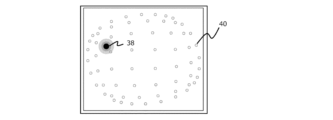
- FIG. 1 shows a diagram for explaining the outline of the technology disclosed in Patent Document 1.
- FIG. 1 shows a constellation corresponding to 32APSK.
- 32APSK 32 symbols indicated by ⁇ or ⁇ in the figure are defined by changing the amplitude and phase of the transmission signal. More specifically, four symbols are defined on the first inner circumference 10, twelve symbols on the second inner circumference 12, and sixteen symbols on the outermost circumference 14.
- Patent Document 1 discloses arranging one or more pilot signals 16 on each of the first inner circumference 10, the second inner circumference 12, and the outermost circumference 14.
- the position of the pilot signal 16 is shared by the transmitter and receiver. Therefore, the receiving device can detect the phase shift occurring in each concentric circle based on the shift between the position of the actually received pilot signal 16 and the position shared in advance.
- the phase shift occurring in the first inner circumference 10 is reflected in the signal. Even when a signal belonging to another concentric circle is received, the phase shift is corrected in the same manner. According to such a method, even if a phase shift occurs in the received signal in a region of high transmission power, the shift can be properly corrected to prevent erroneous transmission of data.
- Non-Patent Document 1 solves the problem of distortion by abandoning the use of the nonlinear region of the amplifier. In other words, with this technique, the amplifier cannot fully demonstrate its inherent ability, and a situation arises that goes against the essential demand of using large power without excessive capital investment.
- the transmitter and receiver may be placed in a dense environment.
- interference power from other cells may reach the receiving device in addition to the signal from the transmitting device of the communication partner.
- the receiving apparatus is likely to misidentify data due to its influence.
- the technique of Non-Patent Document 1 described above cannot provide any solution to the problem caused by such interference power.
- the transmitting device needs to transmit at least as many pilot signals as the number of concentric circles forming the constellation to the receiving device. And the environment of the communication path of the radio signal is not always constant. Therefore, the pilot signal should be executed frequently, preferably for each flow of data communication.
- Patent Document 1 further requires transmission of a larger number of pilot signals when, for example, QAM (Quadrature Amplitude Modulation) is used as the modulation scheme. That is, as described in Patent Document 1, if the modulation scheme is APSK, a plurality of symbols arranged on concentric circles can be corrected with one common phase shift. Therefore, one pilot signal is required for a plurality of symbols arranged on concentric circles.
- QAM Quadrature Amplitude Modulation
- Patent Document 1 enables the use of large power commensurate with the performance of the amplifier, but still leaves room for improvement in terms of data rate.
- Patent Document 1 also cannot provide any solution to the above-mentioned problem caused by interference power from other cells that occurs in a dense environment.
- the present disclosure has been made in view of the above problems, and is a wireless communication system that utilizes the nonlinear region of an amplifier, prevents erroneous transmission of data even in a dense environment, and secures a high data rate.
- a first object is to provide
- a second object of the present disclosure is to provide a wireless communication method that utilizes the nonlinear region of the amplifier, prevents erroneous transmission of data, and ensures a high data rate even in a dense environment. do.
- the present disclosure is a centralized control device capable of instructing a plurality of transmission devices placed in a dense environment on transmission power that satisfies desired communication quality while making use of a nonlinear region in an amplifier provided in the transmission device.
- a third object is to provide
- the present disclosure is a centralized control device capable of instructing a plurality of transmission devices placed in a dense environment on transmission power that satisfies desired communication quality while making use of a nonlinear region in an amplifier provided in the transmission device.
- a fourth object is to provide a wireless communication program for realizing
- a first aspect is a wireless communication system including a plurality of base stations and terminal stations that perform wireless communication using a single-carrier multilevel modulation scheme,
- the base station Equipped with a transmission signal amplifier with variable transmission power, a process of providing specifications regarding input/output characteristics of the transmission signal amplifier to the terminal station; a process of providing transmission power used for data transmission to the terminal station,
- the terminal station A signal point estimation process for estimating a constellation of signal points based on the transmission power and the specification; a process of detecting a coordinate point on the constellation coordinates of the received signal; A process of detecting interference power received from a base station that is not a communication partner; A process of calculating a reception point reflecting the influence of the interference power on the coordinate point; a process of calculating the likelihood of the reception point with the signal point; and identifying the symbol intended by the received signal based on the calculated likelihood.
- a second aspect is a wireless communication method using a plurality of base stations and terminal stations that perform wireless communication using a single-carrier multilevel modulation scheme
- the base station comprises a transmission signal amplifier with variable transmission power, providing from the base station to the terminal station specifications relating to input/output characteristics of the transmission signal amplifier; providing the terminal station with transmission power that the base station is using for data transmission; a signal point estimation step in which the terminal station estimates a constellation of signal points based on the transmission power and the specification; a step in which the terminal station detects a coordinate point on the constellation coordinates of the received signal; a step of detecting interference power received by the terminal station from a base station with which it is not communicating; a step in which the terminal station calculates a reception point in which the influence of the interference power is reflected in the coordinate point; a step of the terminal station calculating the likelihood of the reception point with the signal point; a step in which the terminal station identifies a symbol intended by the received signal based on the calculated likelihood; should be included.
- a third aspect is a centralized control apparatus that controls a wireless communication system including a plurality of base stations and terminal stations that perform wireless communication using a single-carrier multilevel modulation scheme,
- the base station includes a transmission signal amplifier with variable transmission power, and provides the terminal station with specifications relating to the input/output characteristics of the transmission signal amplifier, and provides the terminal station with the transmission power used for data transmission.
- the terminal station performs processing for estimating a constellation of signal points, processing for detecting coordinate points of the received signal on the constellation coordinates, A process of detecting the received interference power, a process of calculating a reception point reflecting the influence of the interference power on the coordinate point, a process of calculating the likelihood of the reception point with the signal point, and the It is configured to perform a process of identifying the symbol intended by the received signal based on the likelihood calculation result and a process of calculating the error rate of the received signal, a process of changing transmission power patterns for the plurality of base stations; a process of collecting the error rate corresponding to each of the patterns; and determining transmission power commands to be given to each of the plurality of base stations so that all of the collected error rates satisfy predetermined requirements.
- a fourth aspect is a wireless communication program for realizing the centralized control device according to the third aspect,
- a process of changing transmission power patterns for the plurality of base stations In the arithmetic processing unit provided in the centralized control device, a process of changing transmission power patterns for the plurality of base stations; a process of collecting the error rate corresponding to each of the patterns; a process of determining transmission power commands to be given to each of the plurality of base stations so that all of the collected error rates satisfy predetermined requirements; It is desirable to include a program that executes
- the first to fourth aspects it is possible to prevent erroneous transmission of data and ensure a high data rate even in a dense environment while utilizing the nonlinear region of the amplifier.
- FIG. 1 is a diagram for explaining an overview of the technology disclosed in Patent Document 1;
- FIG. 1 is a diagram for explaining the overall configuration of a radio communication system according to Embodiment 1 of the present disclosure;
- FIG. 4 is a diagram for explaining a configuration of a comparison target base station to be compared with the base station in Embodiment 1 of the present disclosure;
- FIG. 4 is a diagram showing input/output characteristics of an amplifier built into a base station;
- FIG. 4 is a diagram showing how distortion occurs in a constellation as transmission power increases.
- FIG. 4 is a diagram schematically showing the influence of interference power from other cells on the accuracy of reception points;
- 2 is a block diagram for explaining the configuration of a base station according to Embodiment 1 of the present disclosure;
- FIG. 2 is a block diagram for explaining the configuration of a terminal station according to Embodiment 1 of the present disclosure
- FIG. FIG. 4 is a diagram for explaining a method for a terminal station to calculate a likelihood for a receiving point according to Embodiment 1 of the present disclosure
- 4 is a diagram for explaining a technique in which a terminal station reflects interference power from other cells in likelihood according to Embodiment 1 of the present disclosure; 4 is a flowchart for explaining an example of the flow of processing executed by a centralized control device in Embodiment 1 of the present disclosure to control the transmission power of a base station; 4 is a flowchart for explaining a modification of the flow of processing executed by the centralized control device in Embodiment 1 of the present disclosure to control the transmission power of the base station;
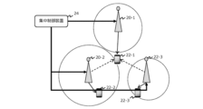
- FIG. 2 shows the overall configuration of a radio communication system according to Embodiment 1 of the present disclosure.
- the wireless communication system of this embodiment includes base stations 20-1 to 20-3.
- base stations 20 when there is no need to distinguish between them, they will be referred to as "base stations 20" with the suffixes omitted.
- FIG. 2 shows terminal stations 22-1 to 22-3 that are in communication with each of the base stations 20.
- FIG. These will also be referred to as "terminal stations 22" with the suffixes omitted when they do not need to be distinguished from each other.
- FIG. 2 shows how the terminal station 22 - 1 is located near the boundary of the communication areas of the three base stations 20 .
- the terminal station 22-1 has established communication with the base station 20-1 as indicated by solid arrows in the figure.
- interference power from other cells reaches the terminal station 22-1, as indicated by the dashed arrow in the figure.
- the wireless communication system of this embodiment also includes a centralized control device 24 .
- the central control device 24 has three base stations 20 shown in FIG.
- the centralized control device 24 can receive information such as bit error rate (BER) or symbol error rate (SER) from the terminal station 22 via the base station 20 .
- BER bit error rate
- SER symbol error rate
- the error rate handled in this embodiment is BER, but the present disclosure is not limited to this, and SER may be handled instead of BER or together with BER.
- FIG. 3 is a block diagram for explaining the configuration of the base station 26 to be compared with the base station 20 in this embodiment.
- the base station 26 of the comparative example has an information bit generator 28 .
- the information bit generator 28 generates information bits to be transmitted to the terminal station 22 .
- the information bit generator 28 may have an error correction coding function or an interleave function.
- the information bits generated by the information bit generator 28 are provided to the data signal modulator 30 .
- the data signal modulator 30 modulates the provided information bits into a data signal.
- the modulation method for example, quadrature amplitude modulation (QAM) or APSK, which can be used for a single-carrier multilevel modulation method, can be considered.
- the data signal generated by the data signal modulating section 30 is provided to the digital-to-analog converting section 32 .
- the digital-to-analog converter 32 converts the digital-modulated data signal into an analog transmission signal.
- the transmission signal generated by the digital-to-analog converter 32 is provided to the transmission signal amplifier 34 .
- the transmission signal amplifier 34 amplifies the transmission signal and provides it to the antenna 36 . Then, the transmission signal is transmitted from the antenna 36 toward the terminal station 22 in the form of a radio signal.
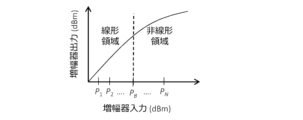
- FIG. 4 shows the input/output characteristics of the transmission signal amplifier 34.
- the output power (vertical axis) of the transmission signal amplifier 34 is proportional to the input power in a region where the input power (horizontal axis) is smaller than PB . Then, in the region where the input power exceeds PB , the proportional relationship is lost.
- a region in which the two are in a proportional relationship will be referred to as a "linear region”
- a region in which the proportional relationship between the two will be lost will be referred to as a "nonlinear region”.
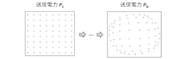
- 64 symbols arranged in a lattice are defined by changing and adjusting the amplitudes of two mutually independent carriers.
- a point on the constellation coordinates where each of these 64 symbols is defined is hereinafter referred to as a "signal point”.
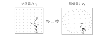
- a point on the constellation coordinates of each data signal that is actually transmitted is called a "receiving point”.
- the reception points form a distortion-free constellation, as shown on the left side of FIG. 5 (transmission power P 1 ).
- transmission power P 1 transmission power
- transmission power P N transmission power
- the terminal station 22 calculates the likelihood of each reception point included in the transmission signal with respect to signal points existing in the vicinity, and based on the result, assigns each reception point to one of 64 symbols. recognize.
- the likelihood calculation can be performed, for example, by the method described in the following document.
- the terminal station 22 performs the above likelihood calculation using signal points forming a constellation without distortion, the reception points generated in the linear domain can be correctly recognized. However, reception points generated in the nonlinear region cannot be recognized correctly because they are shifted from their original positions on the constellation. Therefore, if the transmission signal amplifier 34 uses the non-linear region, the data may be misidentified at the terminal station 22 .
- the base station 26 of the comparative example if the transmission power is limited to the linear region of the transmission signal amplifier 34, it is possible to prevent the constellation of the receiving point from being distorted. Therefore, if such a restriction is applied, misidentification of data at the terminal station 22 can be prevented. However, in that case, a situation arises in which the amplification capability of the transmission signal amplifier 34 cannot be fully utilized.
- the relationship between the transmission power used by the transmission signal amplifier 34 and the distortion occurring in the constellation is grasped in advance, and the relationship is shared between the base station 20 and the terminal station 22 at the start of communication.
- the specification of the transmission signal amplifier 34 is shared at the start of communication, and during communication, the transmission power is transmitted from the base station 20 to the terminal station 22, and the terminal station 22 generates a constellation corresponding to the transmission power. was reproduced to calculate the likelihood. According to such a technique, even if the constellation is distorted in the nonlinear region, it is possible to effectively suppress misidentification of data caused by the distortion.
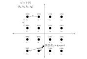
- FIG. 6 is a diagram schematically showing the influence of interference power from other cells on the accuracy of reception points. Specifically, FIG. 6 shows a distorted constellation reproduced by the terminal station 22 and reception points 38 of the signal received by the terminal station 22 superimposed. The likelihood of a reception point 38 is calculated for several signal points 40 located in its vicinity based on the Euclidean distance between them. Then, the signal point 40 for which the greatest likelihood is calculated is recognized as the intended signal of the receiving point 38 . Therefore, in order to correctly recognize data, it is desirable that the position of the receiving point 38 is not blurred.
- the interference power from the other base stations 20-2 and 20-3 reaches the terminal station 22-1 in addition to the signal from the communication partner base station 20-1. are doing. Under such circumstances, the amplitude and phase of the signal reaching the terminal station 22-1 from the base station 20-1 fluctuate due to interference power.
- the reception point 38 shown in FIG. 6 shows a state in which the original position is blurred due to the influence of such fluctuations.
- the shading of the figure showing the reception point 38 simulates the probability distribution of the amplitude and phase of the signal that constitutes the reception point.
- the reception point 38 is in such a state, if the coordinates at a certain time are specified as the coordinates of the reception point 38 for the purpose of likelihood calculation, the coordinates are accompanied by an error. Then, if the likelihood calculation is performed based on the coordinates, the nearest signal point 40 may be erroneously recognized, resulting in data erroneous recognition.
- the error caused by the interference power is equally superimposed on the position of the reception point 38, and then the likelihood with all adjacent signal points is calculated. I decided to As a result, the likelihood associated with a specific signal point is not erroneously increased or decreased, and misrecognition of data in the terminal station 22 is effectively avoided.
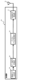
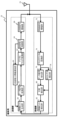
- FIG. 7 is a block diagram for explaining the configuration of the base station 20 in this embodiment.
- elements that are the same as those provided in the base station 26 of the comparative example (see FIG. 3) are denoted by common reference numerals, and description thereof will be omitted or simplified.
- the base station 20 in this embodiment has a transmitting section shown in the upper part of FIG.
- the information bit generator 28 in the base station 26 of the comparative example is replaced with an information bit generator 42 .
- the information bit generator 42 provided in this embodiment generates information bits regarding the specifications of the base station 20 at the stage when communication between the base station 20 and the terminal station 22 is started. Specifically, the modulation scheme used by the base station 20 and the input/output characteristics of the transmission signal amplifier 34 (see FIG. 4) are converted into information bits.
- the information bits generated in this way are transmitted from the base station 20 to the terminal station 22 when communication between the base station 20 and the terminal station 22 is started. Therefore, in the present embodiment, the modulation method used by the base station 20 and the input/output characteristics of the transmission signal amplifier 34 are shared between them at the time when communication between them is started.
- the base station 20 in this embodiment includes a transmission power control section 44 in front of the transmission signal amplifier 34 .
- the transmission power control unit 44 controls transmission power so as to obtain desired communication quality.
- the transmission power control unit 44 can control the transmission power based on the result of information processing performed by itself. Also, the transmission power control unit 44 may receive a command regarding transmission power from the centralized control device 24, and in that case, controls the transmission power according to the received command. The control command of the transmission power control section 44 is provided to the transmission signal amplifier 34 and to the transmission power information notification section 46 .
- the transmission power information notification unit 46 provides the information bit generation unit 42 with the transmission power command value.
- the information bit generator 42 then generates bit information about the current transmission power and includes the information in the transmission data.
- the base station 20 of this embodiment transmits a transmission signal including information on the transmission power to the terminal station 22 at the transmission power set by the transmission power control unit 44 .
- the base station 20 has a receiving section shown in the lower part of FIG.
- This receiver includes a received signal amplifier 48 that receives a received signal from the antenna 36 .
- the received signal amplifier 48 amplifies the received signal with an appropriate gain and provides it to the analog-to-digital converter 50 .
- the analog-to-digital conversion unit 50 is a block for demodulating an analog received signal into a digital signal.
- a signal digitized by the analog-to-digital converter 50 is provided to a data signal equalizer 52 .
- the data signal equalization unit 52 is a block that obtains an estimated value of the transmission signal by back-calculating the amplitude and phase information of the channel response.
- a training signal is exchanged between the base station 20 and the terminal station 22 prior to the data signal.
- the content of the training signal is shared between the base station 20 and the terminal station 22 in advance. Therefore, the base station 20 can detect the influence caused by the communication channel based on the actually received training signal.
- the data signal equalization unit 52 reflects the training result on the data signal received from the terminal station 22 to generate a data signal that cancels out the influence caused by the communication path.
- the data signal generated by the data signal equalization unit 52 is provided to the likelihood calculation unit 54 .
- the likelihood calculator 54 calculates the likelihood of the signal points on the constellation stored by itself for the reception points indicated by the data signal. Then, the signal point with the highest likelihood is recognized as the symbol intended by the current reception point.
- the signal symbolized by the likelihood calculation unit 54 is provided to the information bit detection unit 56 .
- the information bit detector 56 detects received bits from the symbolized signal.
- the information bit detector 56 may also have an error correction decoding function and an interleaving function as required in accordance with the information bit generator 42 .
- FIG. 8 is a block diagram for explaining the configuration of the terminal station 22 in this embodiment.
- the terminal station 22 includes elements that function in substantially the same manner as the elements included in the base station 20 in many respects.
- the transmission section of the terminal station 22 is configured to function in substantially the same manner as the transmission section of the base station 20, except that the transmission power control section 64 does not receive commands from the centralized control device 24. have.
- the receiving section of the terminal station 22 is configured to function in substantially the same manner as the receiving section of the base station 20 except for the other cell interference estimation section 78, the likelihood calculation section 80, and the information bit detection section 82. have.
- the other-cell interference estimation unit 78 detects the magnitude of interference signals received from other base stations 20 other than the base station 20 of the communication partner. Information on the detected interference signal is provided to the likelihood calculator 80 and to the information bit generator 58 for feedback to the base station 20 .
- the likelihood calculation unit 80 calculates the likelihood regarding the receiving point based on the transmission power of the base station 20 and the interference power from other cells. Specifically, the likelihood calculator 80 first identifies the constellation of the received signal based on the specification information of the base station 20 acquired at the start of communication and the current transmission power received together with the data signal. (See Figure 5).
- the modulation scheme used by the base station 20 and the input/output characteristics of the transmission signal amplifier 34 are known information for the terminal station 22 . If such information is known, and if the transmission power actually used is known, the constellation of the received signal, including that accompanied by distortion, can be reproduced. After completing this process, the likelihood calculation unit 80 next uses the selected constellation to calculate the likelihood of the receiving points 38 on which the training result is reflected.
- FIG. 9 is a diagram for explaining an outline of likelihood calculation in this embodiment.
- the left side of FIG. 9 outlines the likelihood calculation when the transmission power is P1 .
- the constellation of the received signal has no distortion in which the signal points 40 are properly arranged in a grid pattern.
- the likelihood calculator 54 refers to the constellation and calculates the likelihood of some of the signal points 40 located near the reception point 38 using a normal distribution for the Euclidean distance between them. Then, the signal point 40 with the highest likelihood is adopted as the symbol corresponding to the receiving point 38 .
- the right side of FIG. 9 outlines the likelihood calculation when the transmission power is P N .
- the constellation of the received signal includes a shift caused by the nonlinearity of the transmitted signal amplifier 34 at each of the signal points 40 .
- the likelihood calculator 54 refers to the constellation with the deviation and calculates the likelihood of the receiving point 38 by the same technique as described above. Then, based on the result, the symbol that the reception point 38 means is specified.
- FIG. 10 is a diagram for explaining a method of reflecting the influence of interference power from other cells on the likelihood.
- a case of calculating the likelihood of signal points of a distortion-free constellation used in 16QAM (Quadrature Amplitude Modulation) will be described below.
- si is a coordinate point represented by a received signal
- n is additive noise
- I is a factor representing interference power from other cells. Since the factor of the interference power I is added together with the additive noise n for the coordinate point si, the Euclidean distance from the receiving point z increases for all signal points compared to the case where the interference power I is not considered.
- the base station 20 can use the nonlinear region of the transmission signal amplifier 34 to transmit a high-power transmission signal. Also, by passing the specifications of the transmission signal amplifier 34 to the terminal station 22 at the start of communication, the terminal station 22 can generate a distorted constellation corresponding to the nonlinear region without the need to provide a large amount of information thereafter. can be reproduced. Then, by executing likelihood calculation using the constellation, it is possible to prevent misidentification of data even for a transmission signal using a nonlinear region. Furthermore, since the likelihood is calculated by adding the factor of the interference power I from other cells to the additive noise n, it is possible to prevent the likelihood of a specific signal point from increasing or decreasing due to the influence of the interference power. be able to. Therefore, according to the wireless communication system of the present embodiment, it is possible to utilize the nonlinear region of the transmission signal amplifier 34, prevent erroneous transmission of data, and secure a high data rate even in a dense environment. can.
- the information bit detection unit 82 of the terminal station 22 has the same function as the information bit detection unit 56 of the base station 20, and also has the function of converting information on the signal error rate BER (Bit Error Rate) into bits. have. The BER information is then provided to the information bit generator 58 of the transmitter.
- BER Bit Error Rate
- the information bit generation unit 58 of the terminal station 22 performs bit generation processing so as to include the information in the transmission signal in order to provide the BER information to the base station 20 of the communication partner.
- the terminal station 22 provides the base station 20 with information on the BER realized by the transmission power currently used by the base station 20 .
- the BER information provided to the base station 20 is provided to the central control device 24. Based on the BER information, the centralized control device 24 controls the transmission power of each base station 20 so as to achieve overall optimization of communications involving the base stations 20 under its control.
- the centralized control device 24 comprises an arithmetic processing unit and a memory device.
- the memory device stores a program to be executed by the arithmetic processing unit.
- This program can be installed in the centralized control device 24 by downloading. Also, this program may be installed in the centralized control device 24 via a recording medium on which the program is recorded.
- FIG. 11 is a flowchart for explaining an example of processing executed by the centralized control device 24 according to the above program. It is assumed that the routine shown in FIG. 11 is repeatedly activated at predetermined intervals while communication is being performed in any of the base stations 20 under the control of the centralized control device 24 .
- step 100 the transmission power for each of the base stations 20 under its control is set.
- step 100 an initial transmission power pattern is set according to a predetermined rule.
- step 100 When the processing of step 100 is completed, the set transmission power is instructed to all base stations 20 under its control. As a result, communication with the transmission power set by the central control device 24 is started in the base station 20 under its control.
- the base station 20 Under its control is provided with BER information from the terminal station 22 of the communication partner.
- the centralized controller 24 collects the BER information via the base station 20 (step 102).
- step 104 it is determined whether or not the collected BER meets preset requirements. For example, it is determined whether or not the error rate BER of all communications involving the subordinate base station 20 is equal to or less than the required threshold. As a result, if it is determined that the BER is equal to or less than the required threshold, it can be determined that the current transmission power pattern is appropriate. In this case, the current routine is terminated while maintaining the transmission power.
- step 108 the transmission power pattern is changed according to a predetermined rule. After that, the transmission power pattern is changed and the processing from step 102 onwards is repeated until it is determined in step 104 that the BER is cleared.
- the transmission power of one base station 20 increases, the SNR of that base station 20 improves, but the constellation distortion increases. In addition, the interference power caused by that base station 20 increases. On the other hand, if the transmission power of one base station 20 is lowered, the SNR for that base station 20 will deteriorate, but the distortion of the constellation and the interference power caused by that base station 20 will decrease. As a result, an increase or decrease in the transmission power of one base station 20 gives advantages and disadvantages to the quality of communication related to that base station 20 and communication related to other base stations 20 . Then, in this embodiment, by repeating trials with various transmission power patterns, it is possible to find a transmission power pattern that achieves overall optimization.
- the pattern search is terminated when a transmission power pattern that satisfies the desired BER requirement is found.
- the present disclosure is not so limited.
- the search may be continued even after the condition for clearing the BER requirement is found to find the optimum transmission power pattern.
- FIG. 12 is a flow chart for explaining the flow of processing to be executed by the centralized control device 24 in order to realize the operation of the above modified example.
- the steps for executing the same processing as the steps shown in FIG. 11 are denoted by common reference numerals, and the description thereof will be omitted or simplified.
- step 102 is followed by step 106 processing. Then, the transmission power pattern is changed (step 108) and BER acquisition is repeated (step 102) until it is determined in step 106 that the search has ended.
- step 110 the optimum transmission power pattern is selected (step 110). Specifically, here, from the BER results accumulated by repeating step 102, a combination in which all communications satisfy the requirements and the total BER is the smallest is selected. Then, when the selected transmission power pattern is commanded to each of the base stations 20, the current routine is terminated.
- the base station 20 provides the specifications of the transmission signal amplifier 34 to the terminal station 22 at the start of wireless communication.
- the terminal station 22 that provided the specifications may be stored in the base station 20, and the information may be stored in the terminal station 22 that received the specifications. Then, for the second and subsequent communications between the two, the transmission and reception of the above specification may be omitted.
- the base station 20 provides the terminal station 22 with the specifications of the transmission signal amplifier 34 as well as information on the modulation scheme used for wireless communication.
- the present disclosure is not so limited. For example, if the modulation scheme used for communication between the base station 20 and the terminal station 22 is determined in advance, providing the information on the modulation scheme can be omitted.
Landscapes
- Engineering & Computer Science (AREA)
- Computer Networks & Wireless Communication (AREA)
- Signal Processing (AREA)
- Mobile Radio Communication Systems (AREA)
Abstract
Description
前記基地局は、
送信電力が可変の送信信号増幅器を備え、
前記送信信号増幅器の入出力特性に関する仕様を前記端末局に提供する処理と、
データ送信に用いている送信電力を前記端末局に提供する処理と、を実行するように構成されており、
前記端末局は、
前記送信電力と前記仕様とに基づいて、信号点のコンスタレーションを推定する信号点推定処理と、
受信信号の、コンスタレーション座標上の座標点を検知する処理と、
通信相手でない基地局から受ける干渉電力を検知する処理と、
前記座標点に、前記干渉電力の影響を反映させた受信点を計算する処理と、
前記受信点について、前記信号点との尤度を計算する処理と、
前記尤度の計算結果に基づいて前記受信信号が意図するシンボルを特定する処理と、を実行するように構成されていることが望ましい。
前記基地局は、送信電力が可変の送信信号増幅器を備え、
前記送信信号増幅器の入出力特性に関する仕様を前記基地局から前記端末局に提供するステップと、
前記基地局がデータ送信に用いている送信電力を前記端末局に提供するステップと、
前記端末局が、前記送信電力と前記仕様とに基づいて、信号点のコンスタレーションを推定する信号点推定ステップと、
前記端末局が、受信信号のコンスタレーション座標上の座標点を検知するステップと、
前記端末局が、通信相手でない基地局から受ける干渉電力を検知するステップと、
前記端末局が、前記座標点に、前記干渉電力の影響を反映させた受信点を計算するステップと、
前記端末局が、前記受信点について、前記信号点との尤度を計算するステップと、
前記端末局が、前記尤度の計算結果に基づいて前記受信信号が意図するシンボルを特定するステップと、
を含むことが望ましい。
前記基地局は、送信電力が可変の送信信号増幅器を備え、前記送信信号増幅器の入出力特性に関する仕様を前記端末局に提供する処理と、データ送信に用いている送信電力を前記端末局に提供する処理と、を実行するように構成されており、
前記端末局は、前記送信電力と前記仕様とに基づいて、信号点のコンスタレーションを推定する処理と、受信信号の、コンスタレーション座標上の座標点を検知する処理と、通信相手でない基地局から受ける干渉電力を検知する処理と、前記座標点に、前記干渉電力の影響を反映させた受信点を計算する処理と、前記受信点について、前記信号点との尤度を計算する処理と、前記尤度の計算結果に基づいて前記受信信号が意図するシンボルを特定する処理と、受信信号の誤り率を計算する処理と、を実行するように構成されており、
前記複数の基地局に対する送信電力のパターンを変更する処理と、
前記パターンの夫々に対応する前記誤り率を収集する処理と、
収集した前記誤り率の全てが既定の要求を満たすように、前記複数の基地局の夫々に与える送信電力の指令を決定する処理と、を実行するように構成されていることが望ましい。
前記集中制御装置が備える演算処理ユニットに、
前記複数の基地局に対する送信電力のパターンを変更する処理と、
前記パターンの夫々に対応する前記誤り率を収集する処理と、
収集した前記誤り率の全てが既定の要求を満たすように、前記複数の基地局の夫々に与える送信電力の指令を決定する処理と、
を実行させるプログラムを含むことが望ましい。
[実施の形態1の全体構成]
図2は、本開示の実施の形態1の無線通信システムの全体構成を示す。図2に示すように、本実施形態の無線通信システムは、基地局20-1~20-3を備えている。以下、それらを区別する必要がない場合は、符号の添え字を省略して「基地局20」と称す。
図3は、本実施形態における基地局20と対比される比較対象の基地局26の構成を説明するためのブロック図である。比較例の基地局26は、情報ビット生成部28を備えている。情報ビット生成部28は、端末局22に伝送したい情報ビットを生成する。情報ビット生成部28は、誤り訂正符号化機能、或いはインターリーブ機能を備えていてもよい。
次に、本実施形態が着目する第二の課題について説明する。
図6は、他セルからの干渉電力が受信点の精度に与える影響を模式的に表した図である。図6は、具体的には、端末局22が再生した歪みを伴うコンスタレーションと、端末局22が受信した信号の受信点38とを重ねて表している。受信点38の尤度は、その近隣に位置する幾つかの信号点40について、両者間のユークリッド距離に基づいて計算される。そして、最も大きな尤度が計算された信号点40が、その受信点38の意図する信号であると認識される。このため、データを正しく認識するためには、受信点38の位置がぼやけていないことが望ましい。
本実施形態において、集中制御装置24は、演算処理ユニットと、メモリ装置を備えている。メモリ装置には、演算処理ユニットで実行させるべきプログラムが記録されている。このプログラムは、ダウンロードにより集中制御装置24にインストールすることができる。また、このプログラムは、そのプログラムを記録した記録媒体を介して集中制御装置24にインストールしてもよい。
ところで、上記の図11に示すルーチンでは、BERが所望の要求をクリアする送信電力パターンが見つかった時点で、パターン探索を終了することとしている。しかしながら、本開示はこれに限定されるものではない。例えば、BERの要求をクリアする条件が見つかった後も探索を続けて、最適な送信電力パターンを探し出すこととしてもよい。
22、22-1~22-3 端末局
24 集中制御装置
34、68 送信信号増幅器
42、58 情報ビット生成部
44、64 送信電力制御部
46、66 送信電力情報通知部
54、80 尤度算出部
78 他セル干渉推定部
82 情報ビット検出部
Claims (8)
- シングルキャリア多値変調方式を用いて無線通信を行う複数の基地局と端末局とを含む無線通信システムであって、
前記基地局は、
送信電力が可変の送信信号増幅器を備え、
前記送信信号増幅器の入出力特性に関する仕様を前記端末局に提供する処理と、
データ送信に用いている送信電力を前記端末局に提供する処理と、を実行するように構成されており、
前記端末局は、
前記送信電力と前記仕様とに基づいて、信号点のコンスタレーションを推定する信号点推定処理と、
受信信号の、コンスタレーション座標上の座標点を検知する処理と、
通信相手でない基地局から受ける干渉電力を検知する処理と、
前記座標点に、前記干渉電力の影響を反映させた受信点を計算する処理と、
前記受信点について、前記信号点との尤度を計算する処理と、
前記尤度の計算結果に基づいて前記受信信号が意図するシンボルを特定する処理と、を実行するように構成されている無線通信システム。 - 前記複数の基地局の夫々に送信電力を指令する集中制御装置を更に含み、
前記端末局は、
受信信号の誤り率を計算する処理と、
前記誤り率を前記基地局に提供する処理と、を更に実行するように構成されており、
前記集中制御装置は、
前記複数の基地局に対する送信電力のパターンを変更する処理と、
前記基地局を介して、前記パターンの夫々に対応する前記誤り率を収集する誤り率収集処理と、
収集した前記誤り率に基づいて、前記複数の基地局の夫々に与える送信電力の指令を決定する指令決定処理と、を実行するように構成されている請求項1に記載の無線通信システム。 - 前記誤り率収集処理は、前記集中制御装置の配下に属する前記基地局が関わる全ての通信についての誤り率を収集する処理を含み、
前記指令決定処理は、
前記誤り率が既定の要求を満たしているか否かを判別する処理と、
前記誤り率の全てが前記既定の要求を満たす送信電力のパターンを探索する処理と、
当該探索の結果得られたパターンに従って、前記複数の基地局に送信電力を指令する処理と、を含む請求項2に記載の無線通信システム。 - 前記誤り率収集処理は、前記複数の基地局で取り得る送信電力のパターンの全てについて前記誤り率を収集し、
前記指令決定処理は、
前記誤り率の全てが前記既定の要求を満たす送信電力のパターンのうち、既定の規則に従って最適なパターンを選択する処理と、
当該最適なパターンに従って、前記複数の基地局に送信電力を指令する処理と、を更に含む請求項3に記載の無線通信システム。 - シングルキャリア多値変調方式を用いて無線通信を行う複数の基地局と端末局とを用いる無線通信方法であって、
前記基地局は、送信電力が可変の送信信号増幅器を備え、
前記送信信号増幅器の入出力特性に関する仕様を前記基地局から前記端末局に提供するステップと、
前記基地局がデータ送信に用いている送信電力を前記端末局に提供するステップと、
前記端末局が、前記送信電力と前記仕様とに基づいて、信号点のコンスタレーションを推定する信号点推定ステップと、
前記端末局が、受信信号のコンスタレーション座標上の座標点を検知するステップと、
前記端末局が、通信相手でない基地局から受ける干渉電力を検知するステップと、
前記端末局が、前記座標点に、前記干渉電力の影響を反映させた受信点を計算するステップと、
前記端末局が、前記受信点について、前記信号点との尤度を計算するステップと、
前記端末局が、前記尤度の計算結果に基づいて前記受信信号が意図するシンボルを特定するステップと、
を含む無線通信方法。 - 前記複数の基地局の夫々に送信電力を指令するステップと、
前記端末局における受信信号の誤り率を計算するステップと、
前記複数の基地局に対する送信電力のパターンを変更するステップと、
前記パターンの夫々に対応する前記誤り率を収集するステップと、
収集した前記誤り率に基づいて、前記複数の基地局の夫々に与える送信電力の指令を決定するステップと、
を含む請求項5に記載の無線通信方法。 - シングルキャリア多値変調方式を用いて無線通信を行う複数の基地局と端末局とを含む無線通信システムを制御する集中制御装置であって、
前記基地局は、送信電力が可変の送信信号増幅器を備え、前記送信信号増幅器の入出力特性に関する仕様を前記端末局に提供する処理と、データ送信に用いている送信電力を前記端末局に提供する処理と、を実行するように構成されており、
前記端末局は、前記送信電力と前記仕様とに基づいて、信号点のコンスタレーションを推定する処理と、受信信号の、コンスタレーション座標上の座標点を検知する処理と、通信相手でない基地局から受ける干渉電力を検知する処理と、前記座標点に、前記干渉電力の影響を反映させた受信点を計算する処理と、前記受信点について、前記信号点との尤度を計算する処理と、前記尤度の計算結果に基づいて前記受信信号が意図するシンボルを特定する処理と、受信信号の誤り率を計算する処理と、を実行するように構成されており、
前記複数の基地局に対する送信電力のパターンを変更する処理と、
前記パターンの夫々に対応する前記誤り率を収集する処理と、
収集した前記誤り率の全てが既定の要求を満たすように、前記複数の基地局の夫々に与える送信電力の指令を決定する処理と、を実行するように構成されている集中制御装置。 - 請求項7に記載の集中制御装置を実現するための無線通信用プログラムであって、
前記集中制御装置が備える演算処理ユニットに、
前記複数の基地局に対する送信電力のパターンを変更する処理と、
前記パターンの夫々に対応する前記誤り率を収集する処理と、
収集した前記誤り率の全てが既定の要求を満たすように、前記複数の基地局の夫々に与える送信電力の指令を決定する処理と、
を実行させるプログラムを含む無線通信用プログラム。
Priority Applications (4)
| Application Number | Priority Date | Filing Date | Title |
|---|---|---|---|
| JP2023544936A JP7601239B2 (ja) | 2021-09-03 | 2021-09-03 | 無線通信システム、無線通信方法、集中制御装置、および無線通信用プログラム |
| PCT/JP2021/032441 WO2023032154A1 (ja) | 2021-09-03 | 2021-09-03 | 無線通信システム、無線通信方法、集中制御装置、および無線通信用プログラム |
| EP21956042.2A EP4398532A4 (en) | 2021-09-03 | 2021-09-03 | COMMUNICATION SYSTEM, WIRELESS COMMUNICATION METHOD, CENTRALIZED CONTROL DEVICE AND PROGRAM FOR WIRELESS COMMUNICATION |
| US18/688,368 US12457144B2 (en) | 2021-09-03 | 2021-09-03 | Wireless communication system, wireless communication method, centralized control device, and wireless communication program |
Applications Claiming Priority (1)
| Application Number | Priority Date | Filing Date | Title |
|---|---|---|---|
| PCT/JP2021/032441 WO2023032154A1 (ja) | 2021-09-03 | 2021-09-03 | 無線通信システム、無線通信方法、集中制御装置、および無線通信用プログラム |
Publications (1)
| Publication Number | Publication Date |
|---|---|
| WO2023032154A1 true WO2023032154A1 (ja) | 2023-03-09 |
Family
ID=85411761
Family Applications (1)
| Application Number | Title | Priority Date | Filing Date |
|---|---|---|---|
| PCT/JP2021/032441 Ceased WO2023032154A1 (ja) | 2021-09-03 | 2021-09-03 | 無線通信システム、無線通信方法、集中制御装置、および無線通信用プログラム |
Country Status (4)
| Country | Link |
|---|---|
| US (1) | US12457144B2 (ja) |
| EP (1) | EP4398532A4 (ja) |
| JP (1) | JP7601239B2 (ja) |
| WO (1) | WO2023032154A1 (ja) |
Citations (4)
| Publication number | Priority date | Publication date | Assignee | Title |
|---|---|---|---|---|
| JPS59112748A (ja) * | 1982-12-06 | 1984-06-29 | Fujitsu Ltd | デ−タ送受信システム |
| JP2010130071A (ja) * | 2008-11-25 | 2010-06-10 | Fujitsu Ltd | 非線形歪み補償装置および非線形歪み補償方法 |
| JP2016174194A (ja) * | 2013-07-30 | 2016-09-29 | シャープ株式会社 | 端末装置、基地局装置及び受信方法 |
| JP2017059889A (ja) | 2015-09-14 | 2017-03-23 | 日本放送協会 | シングルキャリア方式の送信装置及び受信装置 |
Family Cites Families (6)
| Publication number | Priority date | Publication date | Assignee | Title |
|---|---|---|---|---|
| JP4078105B2 (ja) * | 2002-04-08 | 2008-04-23 | シャープ株式会社 | 無線通信システム |
| US20070165728A1 (en) * | 2006-01-17 | 2007-07-19 | Vladimir Parizhsky | Multi-symbol signals including an initial symbol and an extension portion |
| US8804807B2 (en) * | 2012-06-13 | 2014-08-12 | Northrup Grumman Systems Corporation | Iterative equalization with non-linear soft interference cancellation in non-linear satellite channels |
| US9118519B2 (en) * | 2013-11-01 | 2015-08-25 | MagnaCom Ltd. | Reception of inter-symbol-correlated signals using symbol-by-symbol soft-output demodulator |
| US20170279640A1 (en) * | 2016-03-25 | 2017-09-28 | Qualcomm Incorporated | Systems and methods for training field boosting |
| KR102945194B1 (ko) * | 2019-10-31 | 2026-03-26 | 삼성전자주식회사 | 무선통신시스템에서 신호를 처리하는 방법 및 장치 |
-
2021
- 2021-09-03 EP EP21956042.2A patent/EP4398532A4/en active Pending
- 2021-09-03 JP JP2023544936A patent/JP7601239B2/ja active Active
- 2021-09-03 WO PCT/JP2021/032441 patent/WO2023032154A1/ja not_active Ceased
- 2021-09-03 US US18/688,368 patent/US12457144B2/en active Active
Patent Citations (4)
| Publication number | Priority date | Publication date | Assignee | Title |
|---|---|---|---|---|
| JPS59112748A (ja) * | 1982-12-06 | 1984-06-29 | Fujitsu Ltd | デ−タ送受信システム |
| JP2010130071A (ja) * | 2008-11-25 | 2010-06-10 | Fujitsu Ltd | 非線形歪み補償装置および非線形歪み補償方法 |
| JP2016174194A (ja) * | 2013-07-30 | 2016-09-29 | シャープ株式会社 | 端末装置、基地局装置及び受信方法 |
| JP2017059889A (ja) | 2015-09-14 | 2017-03-23 | 日本放送協会 | シングルキャリア方式の送信装置及び受信装置 |
Non-Patent Citations (3)
| Title |
|---|
| JUN YUANAHMED SAFWAT, PROCEEDINGS OF THE IEEE, vol. 92, no. 2, February 2004 (2004-02-01), pages 312 - 339 |
| MARVIN K. SIMONRAMESH ANNAVAJJALA: "On the Optimality of Bit Detection of Certain Digital Modulations", IEEE TRANSACTIONS ON COMMUNICATIONS, vol. 53, no. 2, February 2005 (2005-02-01), pages 299 - 307, XP011127642, DOI: 10.1109/TCOMM.2004.841959 |
| See also references of EP4398532A4 |
Also Published As
| Publication number | Publication date |
|---|---|
| JPWO2023032154A1 (ja) | 2023-03-09 |
| US12457144B2 (en) | 2025-10-28 |
| EP4398532A4 (en) | 2025-09-10 |
| JP7601239B2 (ja) | 2024-12-17 |
| EP4398532A1 (en) | 2024-07-10 |
| US20240406051A1 (en) | 2024-12-05 |
Similar Documents
| Publication | Publication Date | Title |
|---|---|---|
| EP0827652B1 (en) | Digital communications on overlapping channels | |
| US20030179830A1 (en) | Efficient, high fidelity transmission of modulation schemes through power-constrained remote relay stations by local transmit predistortion and local receiver feedback | |
| US12388701B2 (en) | Wireless communication system, wireless communication method, and reception apparatus | |
| CN1327624C (zh) | 无线接收装置和接收滤波方法 | |
| JP7647900B2 (ja) | 無線通信システム、無線通信方法、および無線通信用送信装置 | |
| EP3320620B1 (en) | Apparatus and method for transmitting and receiving wireless signals subject to spectral mask | |
| EP0544875B1 (en) | Apparatus for adjusting signal points, equalizer gains and the like | |
| JP7601239B2 (ja) | 無線通信システム、無線通信方法、集中制御装置、および無線通信用プログラム | |
| JP7316099B2 (ja) | シングルキャリア方式パラメータの最適値検出装置及びプログラム | |
| JP7563615B2 (ja) | 無線通信システム、無線通信方法、および無線通信用送信装置 | |
| US20020167999A1 (en) | Equalizer, receiver, and equalization method and reception method | |
| WO2023148984A1 (ja) | 無線通信方法、無線通信システムおよび無線送信装置 | |
| WO2011078097A1 (ja) | 複合条件判定ユニット、伝送装置、複合条件判定方法 | |
| WO2023148954A1 (ja) | 無線通信方法、無線通信システムおよび無線送信装置 | |
| JP7451030B2 (ja) | 無線受信装置 | |
| KR100758333B1 (ko) | 무선 통신 시스템을 위한 모뎀, 이를 이용한 송신 장치 및그의 송신 전력 제어 방법 | |
| US12489660B2 (en) | Wireless communication system, wireless communication method, and receiver | |
| JP7410519B2 (ja) | 無線通信システム、無線通信方法および送信装置 | |
| JP3792163B2 (ja) | 無線通信装置 | |
| JP5930028B2 (ja) | 自動利得制御装置、自動利得制御方法、及び自動利得制御プログラム | |
| JP3851551B2 (ja) | 送信装置及び受信装置 | |
| JPH07170306A (ja) | 復調装置 | |
| JP2015139190A (ja) | 無線通信装置、無線通信システム及び無線通信方法 | |
| Yoshioka et al. | MLD Interference Canceler for M-Array QAM Signals Applied to FWA Systems |
Legal Events
| Date | Code | Title | Description |
|---|---|---|---|
| 121 | Ep: the epo has been informed by wipo that ep was designated in this application |
Ref document number: 21956042 Country of ref document: EP Kind code of ref document: A1 |
|
| WWE | Wipo information: entry into national phase |
Ref document number: 2023544936 Country of ref document: JP |
|
| WWE | Wipo information: entry into national phase |
Ref document number: 2021956042 Country of ref document: EP |
|
| NENP | Non-entry into the national phase |
Ref country code: DE |
|
| ENP | Entry into the national phase |
Ref document number: 2021956042 Country of ref document: EP Effective date: 20240403 |
|
| WWG | Wipo information: grant in national office |
Ref document number: 18688368 Country of ref document: US |