WO2023038143A1 - 調光窓 - Google Patents
調光窓 Download PDFInfo
- Publication number
- WO2023038143A1 WO2023038143A1 PCT/JP2022/034119 JP2022034119W WO2023038143A1 WO 2023038143 A1 WO2023038143 A1 WO 2023038143A1 JP 2022034119 W JP2022034119 W JP 2022034119W WO 2023038143 A1 WO2023038143 A1 WO 2023038143A1
- Authority
- WO
- WIPO (PCT)
- Prior art keywords
- light control
- light
- layer
- control window
- transparent
- Prior art date
- Legal status (The legal status is an assumption and is not a legal conclusion. Google has not performed a legal analysis and makes no representation as to the accuracy of the status listed.)
- Ceased
Links
Images








Classifications
-
- G—PHYSICS
- G02—OPTICS
- G02F—OPTICAL DEVICES OR ARRANGEMENTS FOR THE CONTROL OF LIGHT BY MODIFICATION OF THE OPTICAL PROPERTIES OF THE MEDIA OF THE ELEMENTS INVOLVED THEREIN; NON-LINEAR OPTICS; FREQUENCY-CHANGING OF LIGHT; OPTICAL LOGIC ELEMENTS; OPTICAL ANALOGUE/DIGITAL CONVERTERS
- G02F1/00—Devices or arrangements for the control of the intensity, colour, phase, polarisation or direction of light arriving from an independent light source, e.g. switching, gating or modulating; Non-linear optics
- G02F1/01—Devices or arrangements for the control of the intensity, colour, phase, polarisation or direction of light arriving from an independent light source, e.g. switching, gating or modulating; Non-linear optics for the control of the intensity, phase, polarisation or colour
- G02F1/13—Devices or arrangements for the control of the intensity, colour, phase, polarisation or direction of light arriving from an independent light source, e.g. switching, gating or modulating; Non-linear optics for the control of the intensity, phase, polarisation or colour based on liquid crystals, e.g. single liquid crystal display cells
- G02F1/133—Constructional arrangements; Operation of liquid crystal cells; Circuit arrangements
- G02F1/1333—Constructional arrangements; Manufacturing methods
- G02F1/1337—Surface-induced orientation of the liquid crystal molecules, e.g. by alignment layers
- G02F1/133769—Surface-induced orientation of the liquid crystal molecules, e.g. by alignment layers comprising an active, e.g. switchable, alignment layer
-
- E—FIXED CONSTRUCTIONS
- E06—DOORS, WINDOWS, SHUTTERS, OR ROLLER BLINDS IN GENERAL; LADDERS
- E06B—FIXED OR MOVABLE CLOSURES FOR OPENINGS IN BUILDINGS, VEHICLES, FENCES OR LIKE ENCLOSURES IN GENERAL, e.g. DOORS, WINDOWS, BLINDS, GATES
- E06B9/00—Screening or protective devices for wall or similar openings, with or without operating or securing mechanisms; Closures of similar construction
- E06B9/24—Screens or other constructions affording protection against light, especially against sunshine; Similar screens for privacy or appearance; Slat blinds
-
- G—PHYSICS
- G02—OPTICS
- G02F—OPTICAL DEVICES OR ARRANGEMENTS FOR THE CONTROL OF LIGHT BY MODIFICATION OF THE OPTICAL PROPERTIES OF THE MEDIA OF THE ELEMENTS INVOLVED THEREIN; NON-LINEAR OPTICS; FREQUENCY-CHANGING OF LIGHT; OPTICAL LOGIC ELEMENTS; OPTICAL ANALOGUE/DIGITAL CONVERTERS
- G02F1/00—Devices or arrangements for the control of the intensity, colour, phase, polarisation or direction of light arriving from an independent light source, e.g. switching, gating or modulating; Non-linear optics
- G02F1/01—Devices or arrangements for the control of the intensity, colour, phase, polarisation or direction of light arriving from an independent light source, e.g. switching, gating or modulating; Non-linear optics for the control of the intensity, phase, polarisation or colour
- G02F1/13—Devices or arrangements for the control of the intensity, colour, phase, polarisation or direction of light arriving from an independent light source, e.g. switching, gating or modulating; Non-linear optics for the control of the intensity, phase, polarisation or colour based on liquid crystals, e.g. single liquid crystal display cells
-
- G—PHYSICS
- G02—OPTICS
- G02F—OPTICAL DEVICES OR ARRANGEMENTS FOR THE CONTROL OF LIGHT BY MODIFICATION OF THE OPTICAL PROPERTIES OF THE MEDIA OF THE ELEMENTS INVOLVED THEREIN; NON-LINEAR OPTICS; FREQUENCY-CHANGING OF LIGHT; OPTICAL LOGIC ELEMENTS; OPTICAL ANALOGUE/DIGITAL CONVERTERS
- G02F1/00—Devices or arrangements for the control of the intensity, colour, phase, polarisation or direction of light arriving from an independent light source, e.g. switching, gating or modulating; Non-linear optics
- G02F1/01—Devices or arrangements for the control of the intensity, colour, phase, polarisation or direction of light arriving from an independent light source, e.g. switching, gating or modulating; Non-linear optics for the control of the intensity, phase, polarisation or colour
- G02F1/13—Devices or arrangements for the control of the intensity, colour, phase, polarisation or direction of light arriving from an independent light source, e.g. switching, gating or modulating; Non-linear optics for the control of the intensity, phase, polarisation or colour based on liquid crystals, e.g. single liquid crystal display cells
- G02F1/133—Constructional arrangements; Operation of liquid crystal cells; Circuit arrangements
- G02F1/1333—Constructional arrangements; Manufacturing methods
- G02F1/1335—Structural association of cells with optical devices, e.g. polarisers or reflectors
- G02F1/133509—Filters, e.g. light shielding masks
- G02F1/133512—Light shielding layers, e.g. black matrix
-
- G—PHYSICS
- G02—OPTICS
- G02F—OPTICAL DEVICES OR ARRANGEMENTS FOR THE CONTROL OF LIGHT BY MODIFICATION OF THE OPTICAL PROPERTIES OF THE MEDIA OF THE ELEMENTS INVOLVED THEREIN; NON-LINEAR OPTICS; FREQUENCY-CHANGING OF LIGHT; OPTICAL LOGIC ELEMENTS; OPTICAL ANALOGUE/DIGITAL CONVERTERS
- G02F1/00—Devices or arrangements for the control of the intensity, colour, phase, polarisation or direction of light arriving from an independent light source, e.g. switching, gating or modulating; Non-linear optics
- G02F1/01—Devices or arrangements for the control of the intensity, colour, phase, polarisation or direction of light arriving from an independent light source, e.g. switching, gating or modulating; Non-linear optics for the control of the intensity, phase, polarisation or colour
- G02F1/13—Devices or arrangements for the control of the intensity, colour, phase, polarisation or direction of light arriving from an independent light source, e.g. switching, gating or modulating; Non-linear optics for the control of the intensity, phase, polarisation or colour based on liquid crystals, e.g. single liquid crystal display cells
- G02F1/133—Constructional arrangements; Operation of liquid crystal cells; Circuit arrangements
- G02F1/1333—Constructional arrangements; Manufacturing methods
- G02F1/1343—Electrodes
- G02F1/134309—Electrodes characterised by their geometrical arrangement
-
- G—PHYSICS
- G02—OPTICS
- G02F—OPTICAL DEVICES OR ARRANGEMENTS FOR THE CONTROL OF LIGHT BY MODIFICATION OF THE OPTICAL PROPERTIES OF THE MEDIA OF THE ELEMENTS INVOLVED THEREIN; NON-LINEAR OPTICS; FREQUENCY-CHANGING OF LIGHT; OPTICAL LOGIC ELEMENTS; OPTICAL ANALOGUE/DIGITAL CONVERTERS
- G02F1/00—Devices or arrangements for the control of the intensity, colour, phase, polarisation or direction of light arriving from an independent light source, e.g. switching, gating or modulating; Non-linear optics
- G02F1/01—Devices or arrangements for the control of the intensity, colour, phase, polarisation or direction of light arriving from an independent light source, e.g. switching, gating or modulating; Non-linear optics for the control of the intensity, phase, polarisation or colour
- G02F1/13—Devices or arrangements for the control of the intensity, colour, phase, polarisation or direction of light arriving from an independent light source, e.g. switching, gating or modulating; Non-linear optics for the control of the intensity, phase, polarisation or colour based on liquid crystals, e.g. single liquid crystal display cells
- G02F1/133—Constructional arrangements; Operation of liquid crystal cells; Circuit arrangements
- G02F1/1333—Constructional arrangements; Manufacturing methods
- G02F1/1343—Electrodes
- G02F1/13439—Electrodes characterised by their electrical, optical, physical properties; materials therefor; method of making
-
- G—PHYSICS
- G02—OPTICS
- G02F—OPTICAL DEVICES OR ARRANGEMENTS FOR THE CONTROL OF LIGHT BY MODIFICATION OF THE OPTICAL PROPERTIES OF THE MEDIA OF THE ELEMENTS INVOLVED THEREIN; NON-LINEAR OPTICS; FREQUENCY-CHANGING OF LIGHT; OPTICAL LOGIC ELEMENTS; OPTICAL ANALOGUE/DIGITAL CONVERTERS
- G02F1/00—Devices or arrangements for the control of the intensity, colour, phase, polarisation or direction of light arriving from an independent light source, e.g. switching, gating or modulating; Non-linear optics
- G02F1/01—Devices or arrangements for the control of the intensity, colour, phase, polarisation or direction of light arriving from an independent light source, e.g. switching, gating or modulating; Non-linear optics for the control of the intensity, phase, polarisation or colour
- G02F1/13—Devices or arrangements for the control of the intensity, colour, phase, polarisation or direction of light arriving from an independent light source, e.g. switching, gating or modulating; Non-linear optics for the control of the intensity, phase, polarisation or colour based on liquid crystals, e.g. single liquid crystal display cells
- G02F1/137—Devices or arrangements for the control of the intensity, colour, phase, polarisation or direction of light arriving from an independent light source, e.g. switching, gating or modulating; Non-linear optics for the control of the intensity, phase, polarisation or colour based on liquid crystals, e.g. single liquid crystal display cells characterised by the electro-optical or magneto-optical effect, e.g. field-induced phase transition, orientation effect, guest-host interaction or dynamic scattering
- G02F1/13712—Devices or arrangements for the control of the intensity, colour, phase, polarisation or direction of light arriving from an independent light source, e.g. switching, gating or modulating; Non-linear optics for the control of the intensity, phase, polarisation or colour based on liquid crystals, e.g. single liquid crystal display cells characterised by the electro-optical or magneto-optical effect, e.g. field-induced phase transition, orientation effect, guest-host interaction or dynamic scattering the liquid crystal having negative dielectric anisotropy
-
- E—FIXED CONSTRUCTIONS
- E06—DOORS, WINDOWS, SHUTTERS, OR ROLLER BLINDS IN GENERAL; LADDERS
- E06B—FIXED OR MOVABLE CLOSURES FOR OPENINGS IN BUILDINGS, VEHICLES, FENCES OR LIKE ENCLOSURES IN GENERAL, e.g. DOORS, WINDOWS, BLINDS, GATES
- E06B9/00—Screening or protective devices for wall or similar openings, with or without operating or securing mechanisms; Closures of similar construction
- E06B9/24—Screens or other constructions affording protection against light, especially against sunshine; Similar screens for privacy or appearance; Slat blinds
- E06B2009/2464—Screens or other constructions affording protection against light, especially against sunshine; Similar screens for privacy or appearance; Slat blinds featuring transparency control by applying voltage, e.g. LCD, electrochromic panels
-
- G—PHYSICS
- G02—OPTICS
- G02F—OPTICAL DEVICES OR ARRANGEMENTS FOR THE CONTROL OF LIGHT BY MODIFICATION OF THE OPTICAL PROPERTIES OF THE MEDIA OF THE ELEMENTS INVOLVED THEREIN; NON-LINEAR OPTICS; FREQUENCY-CHANGING OF LIGHT; OPTICAL LOGIC ELEMENTS; OPTICAL ANALOGUE/DIGITAL CONVERTERS
- G02F2201/00—Constructional arrangements not provided for in groups G02F1/00 - G02F7/00
- G02F2201/08—Constructional arrangements not provided for in groups G02F1/00 - G02F7/00 light absorbing layer
- G02F2201/086—UV absorbing
-
- G—PHYSICS
- G02—OPTICS
- G02F—OPTICAL DEVICES OR ARRANGEMENTS FOR THE CONTROL OF LIGHT BY MODIFICATION OF THE OPTICAL PROPERTIES OF THE MEDIA OF THE ELEMENTS INVOLVED THEREIN; NON-LINEAR OPTICS; FREQUENCY-CHANGING OF LIGHT; OPTICAL LOGIC ELEMENTS; OPTICAL ANALOGUE/DIGITAL CONVERTERS
- G02F2202/00—Materials and properties
- G02F2202/28—Adhesive materials or arrangements
-
- Y—GENERAL TAGGING OF NEW TECHNOLOGICAL DEVELOPMENTS; GENERAL TAGGING OF CROSS-SECTIONAL TECHNOLOGIES SPANNING OVER SEVERAL SECTIONS OF THE IPC; TECHNICAL SUBJECTS COVERED BY FORMER USPC CROSS-REFERENCE ART COLLECTIONS [XRACs] AND DIGESTS
- Y02—TECHNOLOGIES OR APPLICATIONS FOR MITIGATION OR ADAPTATION AGAINST CLIMATE CHANGE
- Y02A—TECHNOLOGIES FOR ADAPTATION TO CLIMATE CHANGE
- Y02A30/00—Adapting or protecting infrastructure or their operation
- Y02A30/24—Structural elements or technologies for improving thermal insulation
-
- Y—GENERAL TAGGING OF NEW TECHNOLOGICAL DEVELOPMENTS; GENERAL TAGGING OF CROSS-SECTIONAL TECHNOLOGIES SPANNING OVER SEVERAL SECTIONS OF THE IPC; TECHNICAL SUBJECTS COVERED BY FORMER USPC CROSS-REFERENCE ART COLLECTIONS [XRACs] AND DIGESTS
- Y02—TECHNOLOGIES OR APPLICATIONS FOR MITIGATION OR ADAPTATION AGAINST CLIMATE CHANGE
- Y02B—CLIMATE CHANGE MITIGATION TECHNOLOGIES RELATED TO BUILDINGS, e.g. HOUSING, HOUSE APPLIANCES OR RELATED END-USER APPLICATIONS
- Y02B80/00—Architectural or constructional elements improving the thermal performance of buildings
Definitions
- the present disclosure relates to a dimming window.
- An example of the light control sheet includes a pair of transparent conductive films, a liquid crystal layer positioned between the transparent conductive films, and a functional layer positioned on the side opposite to the liquid crystal layer with respect to one of the transparent conductive films.
- the light control sheet is configured to be able to have a relatively high haze state and a relatively low haze state depending on whether or not a voltage is applied to the light control sheet.
- the functional layer has a maximum transmittance of 1% or less in a wavelength range of 300 nm or more and 380 nm or less, and a yellowness index YI of 0 or more and 10 or less.
- the light control sheet is applied to the window panes of the windows of buildings.
- a light control window including the light control sheet and the window glass is formed.
- indoor light leaks to the outside through the light control sheet and the transparent member, and the leaked light may attract insects to the light control window.
- Attraction of insects not only detracts from the aesthetics of the dimmable window due to insects flying around the dimmable window, but also by insects colliding with the dimmable window and thereby sticking to the dimmable window. spoil the aesthetic appearance of Therefore, from the viewpoint of suppressing deterioration of the appearance of the light control window, it is desired to suppress the attraction of insects to the light control window.
- a light control window for solving the above problems includes a transparent member and a light control sheet attached to the transparent member.
- the light control sheet includes an adhesive layer that is attached to the transparent member, and a light control layer that is attached to the transparent member by the adhesive layer. and the light control layer having an opaque state. At least one of the adhesive layer and the light control layer includes a filter that partially absorbs light in the visible region.
- Transmittance of light in a wavelength range of 420 nm or less transmitted through the light control window along the first direction from the light control sheet to the transparent member is 10% or less, and from the transparent member to the light control sheet
- the yellowness index YI defined in JIS K 7373:2006 is 10 or less in the light of the standard light source D65 transmitted through the light control window along the second direction toward .
- Insects have high visibility in the ultraviolet region. Specifically, the peak in insect visibility has a top at approximately 360 nm and bottoms at approximately 250 nm and approximately 420 nm. Therefore, when the light control sheet is attached to the surface of the transparent member that is exposed indoors, the transmittance of light in the wavelength range of 420 nm or less among the light leaking from indoors to outdoors through the light control window is 10% or less, it is possible to prevent insects from being attracted to the surface of the light control window exposed to the outdoors.
- the light in the wavelength range of 420 nm or less includes blue light and violet light in the visible region, so the light transmitted from indoors to outdoors through the light control window is yellow. It's easy to get overwhelmed. As a result, when a person staying indoors visually recognizes the light control window, he/she easily feels that the light control window is tinged with yellow.
- the light control window is configured so that the yellowness YI of the light transmitted through the light control window from indoors to the outdoors is 10 or less, so that the indoor resident may feel that the light control window is yellowish. You can suppress the feeling that you are carrying
- the light from the standard light source D65 transmitted through the light control window along the second direction JIS Z 8781- 1:2012 may be 70% or more.
- Y value is 70% or more. Therefore, when a person staying indoors visually recognizes the light control window, it is possible to suppress the feeling that the light control window is dark. In addition, it is possible to suppress the difficulty of visually recognizing the outdoors from indoors.
- the adhesive layer may include an ultraviolet absorption layer, and transmittance of light in a wavelength range of 380 nm or less passing through the light control window along the second direction may be 1% or less. According to this light control window, light in a wavelength band of 380 nm or less incident on the light control sheet is absorbed by the adhesive layer. Thereby, the light resistance of the light control layer is enhanced.
- the wavelength range of 420 nm or less incident on the light control window along the first direction. Reflectance in light may be 10% or less.
- the light control sheet when the light control sheet is attached to the surface of the transparent member that is exposed to the inside, the light that enters the light control window from the outside to the inside is Since the luminosity is high and the reflectance of light is low, attracting insects to the dimming window is further suppressed.
- the transparent member may be made of soda-lime glass.
- a difference value obtained by subtracting the yellowness YI when the light control layer is in the transparent state from the yellowness YI when the light control layer is in the opaque state is 0.2 or less. may be According to this light control window, since the difference value of the yellowness YI is 0.2 or less, it is possible to suppress variations in the yellowness of the light control window due to the difference in the state of the light control layer.
- a transmittance of light in a wavelength range of 620 nm or more incident on the light control window along the first direction may be 10% or less. According to this light-control window, when the resident looks at the light-control window from inside the room, it becomes easier for the resident to suppress the feeling that the light-control window is tinged with yellow.
- the adhesive layer may be a filter. According to this light control window, the adhesive layer can have both a function of attaching the light control layer to the transparent member and a function as a filter.
- the light control layer includes a first transparent electrode layer, a second transparent electrode layer, and a liquid crystal layer positioned between the first transparent electrode layer and the second transparent electrode layer.
- the liquid crystal layer may be the filter. According to this light control window, the liquid crystal layer can have both a function of switching between a transparent state and an opaque state and a function as a filter.
- the attraction of insects to the light control window can be suppressed, and the yellowness of the light control window can be suppressed.
- FIG. 3 is a cross-sectional view schematically showing the structure of a light control window
- FIG. 2 is a cross-sectional view schematically showing a first example of the structure of a light control layer included in the light control sheet shown in FIG. 1
- 2 is a cross-sectional view schematically showing a second example of the structure of the light control layer included in the light control sheet shown in FIG. 1.
- FIG. 1. It is sectional drawing which shows typically the 3rd example in the structure of the light control layer with which the light control sheet shown in FIG. 1 is provided. 1. It is sectional drawing which shows typically the 4th example in the structure of the light control layer with which the light control sheet shown in FIG. 1 is provided.
- FIG. 1 It is sectional drawing which shows typically the 3rd example in the structure of the light control layer with which the light control sheet shown in FIG. 1 is provided. 1.
- FIG. 1 shows typically the 4th example in the structure of the light control layer with which the light control sheet shown in FIG. 1 is provided.
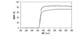
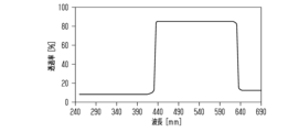
- FIG. 10 is a graph showing transmittance spectra in the dimming windows of Comparative Examples 1-1 and 2-1;
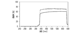
- FIG. 10 is a graph showing transmittance spectra of first filters included in the dimming windows of Comparative Example 1-3 and Example 2-1.
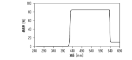
- FIG. 10 is a graph showing transmittance spectra of the dimming windows of Comparative Example 1-3 and Example 2-1;
- FIG. 10 is a graph showing the transmittance spectra of the first filters included in the dimming windows of Examples 1-1 and 2-2.
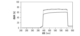
- FIG. 10 is a graph showing transmittance spectra of the dimming windows of Examples 1-1 and 2-2.
- FIG. 10 is a graph showing the transmittance spectra of the first filters included in the dimming windows of Comparative Examples 1-5 and 2-4.
- 10 is a graph showing transmittance spectra of dimming windows of Comparative Examples 1-5 and Comparative Examples 2-4.
- 10 is a graph showing the transmittance spectra of the first filters included in the dimming windows of Examples 1-2 and 2-3.
- FIG. 10 is a graph showing transmittance spectra of dimming windows of Examples 1-1 and 2-3.
- FIG. 10 is a graph showing the transmittance spectra of the first filters included in the dimming windows of Comparative Examples 1-7 and 2-6.
- 10 is a graph showing transmittance spectra of dimming windows of Comparative Examples 1-7 and Comparative Examples 2-6.
- 10 is a graph showing the transmittance spectra of the first filters included in the dimming windows of Examples 1-3 and 2-4.
- 10 is a graph showing transmittance spectra of dimming windows of Examples 1-3 and 2-4. 10 is a graph showing the transmittance spectra of the first filters included in the dimming windows of Comparative Examples 1-9 and 2-8. 10 is a graph showing transmittance spectra of dimming windows of Comparative Examples 1-9 and 2-8. 10 is a graph showing the transmittance spectra of the first filters included in the dimming windows of Examples 1-4 and 2-5. 4 is a graph showing the transmittance spectra of the dimming windows of Examples 1-4 and 2-5.
- the visible region means a wavelength region of more than 380 nm and 750 nm or less
- the ultraviolet region means a wavelength region of 380 nm or less.
- the light control window includes a light control sheet 10 and a transparent member TM.
- the transparent member TM is made of, for example, soda-lime glass.
- the transparent member TM is not limited to soda-lime glass, and may be made of glass other than soda-lime glass.
- the transparent member TM may be made of, for example, quartz glass, borosilicate glass, lead glass, fluoride glass, or the like.
- the transparent member TM may be made of synthetic resin.
- the transparent member TM preferably has a gas barrier layer on the surface to which the light control sheet 10 is attached. This prevents the gas emitted from the transparent member TM from reaching the light control sheet 10 .
- the transparent member TM is attached to windows, doors, roofs, and the like of various buildings.
- the transparent member TM may have a flat plate shape or may be curved.
- the direction from the light control sheet 10 toward the transparent member TM is the first direction D1.
- the direction from the transparent member TM toward the light control sheet 10 is the second direction D2.
- the light control sheet 10 is attached to the surface located inside the building, out of the pair of surfaces of the transparent member TM. Therefore, the first direction D1 is the direction from the interior of the building with the dimming window to the exterior.
- the second direction D2 is the direction from the outside to the inside of the building having the dimming windows.
- the light control sheet 10 is attached to the transparent member TM.
- the light control sheet 10 includes an adhesive layer 11 and a light control layer 12. - ⁇ The adhesive layer 11 is attached to the transparent member TM.
- the light control layer 12 is attached to the transparent member TM with the adhesive layer 11 .
- the light modulating layer 12 has a transparent state and an opaque state depending on whether or not a voltage is applied to the light modulating layer 12 .
- At least one of the adhesive layer 11 and the light control layer 12 contains a filter that partially absorbs light in the visible region. That is, either one of the adhesive layer 11 and the light control layer 12 may contain the filter, or both the adhesive layer 11 and the light control layer 12 may contain the filter.
- the adhesive layer 11 may have a single layer structure or a multilayer structure.
- the layer functions as a filter and has adhesiveness to the transparent member TM.
- the adhesive layer 11 contains a filter and has a multilayer structure, at least one layer contained in the adhesive layer 11 functions as a filter. That is, only one of the layers included in the adhesive layer 11 may function as a filter, or two or more of the layers may function as filters. In this case, the layer functioning as a filter and the adhesive layer may be different layers or the same layer.
- the adhesive layer 11 may include an ultraviolet absorbing layer.
- a transmittance of light in a wavelength range of 380 nm or less that passes through the light control window along the second direction D2 may be 1% or less. That is, the light control window may be configured such that the transmittance of light in the wavelength range of 380 nm or less is 1% or less by providing the adhesive layer 11 with an ultraviolet absorption layer.
- the transmittance of light in the wavelength range of 380 nm or less through the light control window along the second direction D2 is the total light transmittance.
- the total light transmittance is measured by a method conforming to JIS K 7361-1:1997 "Plastics-Testing method for total light transmittance of transparent materials-Part 1: Single beam method".
- the light in the wavelength band of 380 nm or less incident on the light control sheet 10 is absorbed by the adhesive layer 11 .
- the light resistance of the light control layer 12 is improved.
- deterioration of the liquid crystal layer and the transparent base material, which will be described later, of the light control layer 12 due to light in the wavelength band of 380 nm or less is suppressed.
- light in a wavelength band of 380 nm or less that is, ultraviolet light, is incident on the light control sheet 10 from the second direction D2.
- the adhesive layer 11 is positioned between the transparent member TM and the light control layer 12, the light incident on the light control sheet 10 along the second direction D2 is absorbed in the adhesive layer 11, thereby It is difficult for ultraviolet rays to reach the layer 12 . Therefore, deterioration of the liquid crystal layer and the transparent base material included in the light control layer 12 can be easily suppressed.
- the layer 11 When the adhesive layer 11 has a single layer structure, the layer functions as an ultraviolet absorbing layer. In this case, the adhesive layer 11 functions as an ultraviolet absorbing layer and has adhesiveness to the transparent member TM.
- the adhesive layer 11 When the adhesive layer 11 has a multilayer structure, at least one layer included in the adhesive layer 11 functions as an ultraviolet absorption layer. That is, only one of the layers included in the adhesive layer 11 may function as a filter, or two or more of the layers may function as filters. In this case, the layer functioning as an ultraviolet absorbing layer and the adhesive layer may be different layers or the same layer.
- the adhesive layer 11 is formed from various transparent adhesives.
- the adhesive may be, for example, an optical clear adhesive (OCA) or the like.
- OCA optical clear adhesive
- the adhesive layer 11 may contain various colorants, for example.
- the adhesive layer 11 may contain only one colorant, or may contain two or more colorants.
- the adhesive layer 11 contains a first colorant that absorbs light in the first wavelength band in the visible region and a first colorant in the visible region. and a second colorant that absorbs light in a second wavelength band different from the wavelength band.
- the thickness of the adhesive layer 11 may be, for example, 10 ⁇ m or more and 75 ⁇ m or less.
- the adhesive layer 11 can have both the function of attaching the light control layer 12 to the transparent member TM and the function of the filter.
- the adhesion layer 11 may also contain an ultraviolet absorber.
- the layer in contact with the light control layer 12 and the layer in contact with the transparent member TM among the plurality of layers may be formed from the transparent adhesive described above.
- the layer formed from the adhesive may contain the ultraviolet absorber, or a layer different from the layer formed from the adhesive may contain the ultraviolet absorber.
- the layer formed from the adhesive may contain the coloring agent described above, or a layer different from the layer formed from the adhesive may contain the coloring agent.
- the light control layer 12 includes a first transparent electrode layer 21, a second transparent electrode layer 22, a liquid crystal layer 23, a first transparent substrate 24, and a second transparent substrate 25.
- the liquid crystal layer 23 is positioned between the first transparent base material 24 and the second transparent base material 25 in the thickness direction of the light modulating layer 12 .
- the first transparent substrate 24 supports the first transparent electrode layer 21 .
- a second transparent substrate 25 supports the second transparent electrode layer 22 .
- the liquid crystal layer 23 is positioned between the first transparent electrode layer 21 and the second transparent electrode layer 22 in the thickness direction of the dimming layer 12 .
- the first transparent electrode layer 21, the second transparent electrode layer 22, the liquid crystal layer 23, the first transparent substrate 24, and , or the second transparent substrate 25 may function as a filter.
- the first transparent substrate 24 and the second transparent substrate 25 is configured to function as a filter. That is, either one of the first transparent base material 24 and the second transparent base material 25 may be configured to function as a filter, or both the first transparent base material 24 and the second transparent base material 25 may be configured to function as filters. It may be configured to function as a filter.
- the liquid crystal layer 23 may be a filter. In this case, the liquid crystal layer can have both a function of switching between a transparent state and an opaque state and a function as a filter.
- the type of the light modulating layer 12 is a normal type. That is, the light control layer 12 has a transparent state when a voltage is applied between the first transparent electrode layer 21 and the second transparent electrode layer 22 . On the other hand, when no voltage is applied between the first transparent electrode layer 21 and the second transparent electrode layer 22, the light control layer 12 has an opaque state. The haze of the light modulating layer 12 in the transparent state is lower than the haze of the light modulating layer 12 in the opaque state.
- the transparent state means a state in which the haze value of the light modulating layer 12 is saturated at the minimum value.
- the opaque state means a state in which the haze value of the light modulating layer 12 is saturated at the maximum value. Haze is determined by a method conforming to JIS K 7136:2000 "Plastics - Determination of haze of transparent materials".
- Materials for forming the transparent electrode layers 21 and 22 include, for example, indium tin oxide, fluorine-doped tin oxide, tin oxide, zinc oxide, carbon nanotubes, poly(3,4-ethylenedioxythiophene), and silver. It may be any one selected from the group consisting of:
- the thickness of each of the transparent electrode layers 21 and 22 may be, for example, 0.005 ⁇ m or more and 0.1 ⁇ m or less. This makes it possible to reduce cracks that may occur when the light control sheet 10 is bent while ensuring proper driving of the light control sheet 10 .
- the liquid crystal layer 23 includes a transparent resin layer and a liquid crystal composition.
- the resin layer includes a plurality of domains, which are voids formed in the resin layer.
- the liquid crystal composition is filled in the domains of the resin layer.
- a liquid crystal composition includes a plurality of liquid crystal molecules. Examples of liquid crystal molecules include Schiff bases, azos, azoxys, biphenyls, terphenyls, benzoates, tolans, pyrimidines, cyclohexanecarboxylates, phenylcyclohexanes, and dioxanes. is any selected from the group Liquid crystal molecules are positive liquid crystals with positive dielectric anisotropy.
- the liquid crystal composition may also contain a polymerizable composition for forming a resin layer, a dichroic dye, and the like.
- a polymerizable composition is a monomer or oligomer that can be polymerized by irradiation with ultraviolet light.
- the resin layer is a polymer of the polymerizable composition.
- the polymerizable composition is a monomer or polymer that can be polymerized by irradiation with ultraviolet light.
- each transparent base material 24, 25 may be a synthetic resin or an inorganic compound.
- Synthetic resins are, for example, polyesters, polyacrylates, polycarbonates and polyolefins. Polyesters are, for example, polyethylene terephthalate and polyethylene naphthalate.
- Polyacrylate is, for example, polymethyl methacrylate.
- Inorganic compounds include, for example, silicon dioxide, silicon oxynitride, and silicon nitride.
- the thickness of each of the transparent substrates 24 and 25 may be, for example, 16 ⁇ m or more and 250 ⁇ m or less. Since the thickness of the transparent substrates 24 and 25 is 16 ⁇ m or more, the processing and application of the light control sheet 10 are easy. Since the thickness of the transparent substrates 24 and 25 is 250 ⁇ m or less, it is possible to manufacture the light control sheet 10 by roll-to-roll.
- the light control layer 12 may include transparent electrode layers 21 and 22, a liquid crystal layer 23, and a first filter 26 different from the transparent substrates 24 and 25.
- the first filter 26 is located on the opposite side of the first transparent substrate 24 to the first transparent electrode layer 21 .
- the first filter 26 may have a single layer structure or a multilayer structure. Also, the first filter 26 may be positioned on the side opposite to the second transparent electrode layer 22 with respect to the second transparent substrate 25 .
- the first filter 26 is made of, for example, a base material and a coloring agent.
- the matrix may be, for example, a transparent synthetic resin.
- the first filter 26 may contain various colorants.
- the first filter 26 may contain only one colorant, or may contain two or more colorants.
- the first filter 26 includes a first colorant that absorbs light in the first wavelength band in the visible region and a first colorant that absorbs light in the first wavelength band in the visible region. and a second colorant that absorbs light in a second wavelength band different from the first wavelength band.
- the light modulating layer 12 may include a second filter 27 different from the first filter 26 in addition to the first filter 26 described above.
- the first filter 26 is located on the side opposite to the first transparent electrode layer 21 with respect to the first transparent substrate 24, and the second filter 27 is located with respect to the second transparent substrate 25. is located on the side opposite to the second transparent electrode layer 22 .
- the first filter 26 may have a single layer structure or a multilayer structure.
- the second filter 27 may have a single-layer structure or a multilayer structure like the first filter 26 .
- the second filter 27 is made of, for example, a base material and a coloring agent.
- the matrix may be, for example, a transparent synthetic resin.
- the second filter 27 may contain various colorants.
- the second filter 27 may contain only one colorant, or may contain two or more colorants.
- the second filter 27 includes a first colorant that absorbs light in the first wavelength band in the visible region and a first colorant that absorbs light in the first wavelength band in the visible region. and a second colorant that absorbs light in a second wavelength band different from the first wavelength band.
- the wavelength band of light absorbed by the first filter 26 and the wavelength band of light absorbed by the second filter 27 may be the same or different.
- the type of the light control layer 12 is not limited to the normal type described above, and may be a reverse type. That is, the light control layer 12 has a transparent state when no voltage is applied between the first transparent electrode layer 21 and the second transparent electrode layer 22 . On the other hand, in a state where a voltage is applied between the first transparent electrode layer 21 and the second transparent electrode layer 22, the light control layer 12 has an opaque state. The haze of the light modulating layer 12 in the transparent state is lower than the haze of the light modulating layer 12 in the opaque state.
- FIG. 5 shows the structure of the reverse type light control layer 12 .
- the light modulating layer 12 includes, in addition to the first transparent electrode layer 21, the second transparent electrode layer 22, the liquid crystal layer 23, the first transparent substrate 24, and the second transparent substrate 25, It comprises a first alignment layer 28 and a second alignment layer 29 .
- the first alignment layer 28 is positioned between the first transparent electrode layer 21 and the liquid crystal layer 23 in the thickness direction of the light modulating layer 12 .
- the second alignment layer 29 is positioned between the second transparent electrode layer 22 and the liquid crystal layer 23 in the thickness direction of the light modulating layer 12 .
- the first alignment layer 28 and the second alignment layer 29 are vertical alignment films.
- the first alignment layer 28 is such that the long axis of the liquid crystal molecules contained in the liquid crystal layer 23 is aligned with the first alignment layer 28 .
- the liquid crystal molecules are oriented perpendicular to the surface of the substrate.
- the second alignment layer 29 orients the liquid crystal molecules contained in the liquid crystal layer 23 so that the long axes of the liquid crystal molecules are perpendicular to the surface of the second alignment layer 29 .
- Materials for forming the alignment layers 28 and 29 are organic compounds, inorganic compounds, and mixtures thereof.
- Organic compounds include, for example, polyimides, polyamides, polyvinyl alcohols, and cyanide compounds.
- Inorganic compounds include silicon oxide and zirconium oxide.
- the material for forming the alignment layers 28 and 29 may be silicone. Silicones are compounds that have an inorganic portion and an organic portion.
- the thickness of each alignment layer 28, 29 may be, for example, 0.02 ⁇ m or more and 0.5 ⁇ m or less.
- the liquid crystal molecules included in the liquid crystal layer 23 are negative liquid crystal molecules having negative dielectric anisotropy.
- the light control sheet 10 may include functional layers other than the adhesive layer 11 and the light control layer 12 described above. Other functional layers may be, for example, an ultraviolet absorbing layer and a hard coat layer. When the light control sheet 10 is provided with a functional layer, the functional layer may be positioned on the transparent substrate on which the adhesive layer 11 is not positioned, out of the first transparent substrate 24 and the second transparent substrate 25 .
- the transmittance of light in the wavelength range of 420 nm or less is 10% or less in the light that passes through the light control window from indoors to outdoors.
- the transmittance is the total light transmittance and is measured by the method based on JIS K 7361-1:1997 mentioned above.
- the yellowness index YI is 10 or less in the light of the standard light source D65 that passes through the light control window from the outside to the inside.
- Insects have high visibility in the ultraviolet region. Specifically, the peak in insect visibility has a top at approximately 360 nm and bottoms at approximately 250 nm and approximately 420 nm. Therefore, of the light that leaks from indoors to the outdoors through the light control window, if the transmittance of light in the wavelength range of 420 nm or less is 10% or less, insects are attracted to the surface of the light control window that is exposed to the outdoors. can be suppressed.
- the light in the wavelength range of 420 nm or less includes blue light and violet light in the visible region, so the light transmitted from indoors to outdoors through the light control window is yellow. It's easy to get overwhelmed. As a result, when a person staying indoors visually recognizes the light control window, he/she easily feels that the light control window is tinged with yellow.
- the light control window provided with the light control sheet 10 of the present disclosure is configured so that the yellowness YI is 10 or less in the light transmitted through the light control window from indoors to outdoors. This suppresses the feeling that the dimming window is tinged with yellow.
- Standard light source D65 is specified in JIS Z 8720:2012 “Standard illuminant (standard light) and standard light source for colorimetry”.
- the yellowness YI in Condition 2 is a value calculated by the calculation method specified in JIS K 7373:2006 “Plastics - Determination of yellowness and yellowness”.
- the dimming window preferably satisfies at least one of conditions 3 to 6 below. That is, the dimming window may satisfy only one of the conditions 3 to 6, or may satisfy two or more of the conditions 3 to 6.
- the Y value of the light transmitted from the outside to the inside through the light control window is 70% or more, so when the indoor resident visually recognizes the light control window, , it is possible to suppress the feeling that the dimming window is dark. In addition, it is possible to suppress the difficulty of visually recognizing the outdoors from indoors.
- the light control window satisfies the condition 4, among the light incident on the light control sheet 10 from the outdoors toward the inside, the reflectance of the light with high visibility for insects is low, so insects are attracted to the light control window. is further reduced.
- the difference value of the yellowness YI is 0.2 or less. Therefore, it is possible to suppress the variation in the yellowness of the light control window due to the difference in the state of the light control layer 12. be.
- the Y value in condition 3 is calculated by the calculation method specified in JIS Z 8781-1:2012 "Colorimetry-Part 1: Color matching functions of CIE colorimetric standard observer”.
- the transmittance under condition 6 is the total light transmittance and is measured by the method according to JIS K 7361-1:1997 mentioned above.
- the filter included in the light control window can contain a coloring agent as described above.
- the coloring agent may be a coloring agent having an absorption wavelength band in the wavelength region of 420 nm or less.
- a filter may contain only 1 type of coloring agents, and may contain 2 or more types.
- the colorant may be, for example, one or more selected from the group consisting of triazine-based compounds, benzophenone-based compounds, benzotriazole-based compounds, and cyanoacrylate-based compounds. That is, the filter may contain only one compound selected from the group, or may contain two or more compounds.
- the filter may contain two or more coloring agents contained in the same series of compounds, or the coloring agent contained in the first series of compounds, and a colorant contained in a second series of compounds different from the first series.
- the filter included in the light control window can contain a coloring agent.
- the coloring agent may be a coloring agent having an absorption wavelength band in the wavelength region of 620 nm or more.
- a filter may contain only 1 type of coloring agents, and may contain 2 or more types.
- the coloring agent may be, for example, a chromatic coloring agent, and the chromatic coloring agent may be, for example, a blue pigment.
- Blue pigments may be, for example, monoazo blue pigments, methine or polymethine blue pigments.
- the colorant may be, for example, an infrared absorbing agent.
- the infrared absorbent may be, for example, a cyanine-based compound, a phthalocyanine-based compound, a squarylium-based compound, a croconium-based compound, a diimmonium-based compound, a perylene-based compound, or a pyrrolopyrrole-based compound. From the viewpoint that the light control window satisfies Condition 6, the filter provided in the light control window may contain both a chromatic colorant and an infrared absorber.
- the resin layer included in the liquid crystal layer 23 may include the various colorants described above.
- FIGS. 6 to 22 Examples and comparative examples will be described with reference to FIGS. 6 to 22 and Tables 1 to 4.
- FIG. Of FIGS. 6 to 22, FIGS. 6, 8, 10, 12, 14, 16, 18, 20, and 22 each show the transmittance spectrum at the dimming window. ing.
- the transmittance in the transmittance spectrum is the total light transmittance.
- the solid line shows the spectrum when the normal type light control window is in the opaque state and the voltage applied to the light control layer is 0 V, and the normal type light control window is in the transparent state and the light control is performed.
- the dashed line shows the spectrum when the voltage applied to the photolayer is 40V.
- the spectrum in the case where the reverse type light control window is in the transparent state and the voltage applied to the light control layer is 0 V is shown by the dashed line
- the reverse type light control window is in the opaque state and the light control
- the spectrum for a voltage of 40 V applied to the layer is shown by the dashed-double-dot line.
- FIGS. 7, 9, 11, 13, 15, 17, 19, and 21 each show the transmittance spectrum of the first filter provided in the dimming window.
- the transmittance in the transmittance spectrum is the total light transmittance.
- FIG. 6 shows the transmittance spectra of the dimming windows of Comparative Examples 1-1 and 2-1.
- FIG. 7 shows the transmittance spectra of the first filters included in the light control windows of Comparative Example 1-3 and Example 2-1
- FIG. 8 shows the light control windows of Comparative Example 1-3 and Example 2-1.
- 2 shows the transmittance spectrum at .
- FIG. 9 shows the transmittance spectra of the first filters included in the photochromic windows of Examples 1-1 and 2-2
- FIG. 10 shows the transmittance spectra of the photochromic windows of Examples 1-1 and 2-2. 2 shows the transmittance spectrum at .
- FIG. 11 shows the transmittance spectra of the first filters included in the light control windows of Comparative Examples 1-5 and 2-4
- FIG. 12 shows the light control windows of Comparative Examples 1-5 and 2-4
- 2 shows the transmittance spectrum at .
- FIG. 13 shows the transmittance spectra of the first filters included in the photochromic windows of Examples 1-2 and 2-3
- FIG. 14 shows the transmittance spectra of the photochromic windows of Examples 1-2 and 2-3. 2 shows the transmittance spectrum at .
- FIG. 15 shows the transmittance spectra of the first filters included in the light control windows of Comparative Examples 1-7 and 2-6
- FIG. 16 shows the light control windows of Comparative Examples 1-7 and 2-6
- 2 shows the transmittance spectrum at
- FIG. 17 shows the transmittance spectra of the first filters included in the photochromic windows of Examples 1-3 and 2-4
- FIG. 18 shows the transmittance spectra of the photochromic windows of Examples 1-3 and 2-4. 2 shows the transmittance spectrum at .
- FIG. 19 shows the transmittance spectra of the first filters included in the light control windows of Comparative Examples 1-9 and 2-8
- FIG. 20 shows the light control windows of Comparative Examples 1-9 and 2-8
- 2 shows the transmittance spectrum at .
- FIG. 21 shows the transmittance spectra of the first filters included in the photochromatic windows of Examples 1-4 and 2-5
- FIG. 22 shows the photochromatic windows of Examples 1-4 and 2-5. 2 shows the transmittance spectrum at .
- a plate member made of soda-lime glass and having a thickness of 3 mm was prepared as a transparent member.
- a normal type light control sheet composed of an adhesive layer containing an ultraviolet absorber and a light control layer was prepared.
- a light control layer including a liquid crystal layer, a pair of transparent electrode layers, a pair of transparent substrates, an ultraviolet absorption layer, and a hard coat layer was prepared.
- One of the transparent substrates is attached to the transparent member by means of an adhesive layer, the above-mentioned ultraviolet absorbing layer is laminated on the other transparent substrate, and the hard coat layer is laminated on the ultraviolet absorbing layer. .
- liquid crystal layer a liquid crystal layer containing a plurality of domains and filled with a liquid crystal composition was prepared. Also, as a pair of transparent electrode layers, transparent electrode layers made of ITO were prepared. Also, a transparent base material made of PET was prepared as a transparent base material.
- a plurality of first filters were designed, and the optical characteristics of the normal-type dimming windows equipped with each first filter were calculated through simulation.
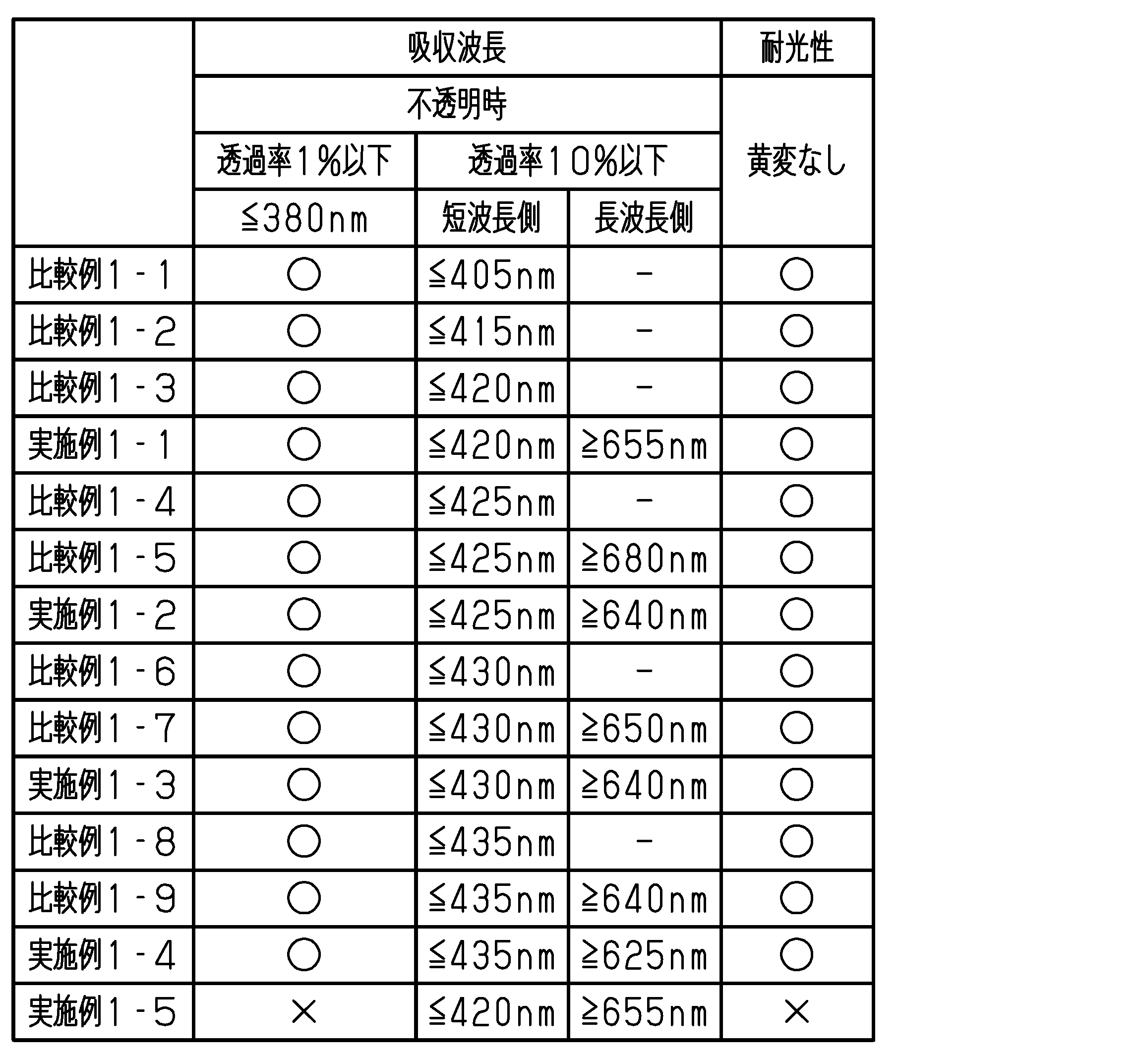
- Table 1 shows the wavelength range absorbed by each light control window and the light resistance of the light control window.
- the light control window of comparative example 1-1 does not have the first filter.
- the light control windows of Comparative Examples other than Comparative Example 1-1 and the light control windows of all Examples have the first filter.
- the light control windows of Examples 1-1 to 1-4 and Comparative Examples 1-1 to 1-9 had a transmittance of 1% or less in the wavelength range of 380 nm or less. Admitted.
- the incidence of ultraviolet rays on the light control windows is suppressed, thereby preventing yellowing of the light control sheets. suppressed.
- the light control windows of Comparative Examples 1-2 to 1-4, 1-6, and 1-8 only the light in the short wavelength side in the visible region is was combined with a first filter that absorbs As a result, it was confirmed that the light control windows of Comparative Examples 1-2 to 1-4, 1-6, and 1-8 had a transmittance of 10% or less for light in the wavelength region on the short wavelength side in the visible region. rice field.
- the dimming windows of Comparative Examples 1-3 were observed to exhibit the transmittance spectrum shown in FIG. 8 by including a first filter exhibiting the transmittance spectrum shown in FIG.
- the light in the wavelength region on the short wavelength side in the visible region and , and a first filter that absorbs light in the longer wavelength region in the visible region was found to be 10% or less.
- the dimming windows of Comparative Examples 1-5 exhibited the transmittance spectrum shown in FIG. 12 by including the first filter showing the transmittance spectrum shown in FIG. Further, it was confirmed that the light control windows of Comparative Examples 1-7 exhibit the transmittance spectrum shown in FIG. 16 by providing the first filter exhibiting the transmittance spectrum shown in FIG. Further, it was confirmed that the light control windows of Comparative Examples 1-9 exhibit the transmittance spectrum shown in FIG. 20 by providing the first filter exhibiting the transmittance spectrum shown in FIG.
- the light in the wavelength region on the short wavelength side in the visible region and the light in the wavelength region on the long wavelength side in the visible region was combined with a first filter that absorbs light in the wavelength range of .
- the transmittance of light in the short wavelength region in the visible region and light in the long wavelength region in the visible region is 10% or less. was found to be
- the light control window of Example 1-1 exhibited the transmittance spectrum shown in FIG. 10 by including the first filter showing the transmittance spectrum shown in FIG. It was observed that the light control window of Examples 1-2 exhibited the transmittance spectrum shown in FIG. 14 by including the first filter exhibiting the transmittance spectrum shown in FIG.
- the dimming windows of Examples 1-3 were observed to exhibit the transmittance spectra shown in FIG. 18 by including a first filter exhibiting the transmittance spectra shown in FIG.
- the dimming windows of Examples 1-4 were observed to exhibit the transmittance spectra shown in FIG. 22 by including a first filter exhibiting the transmittance spectra shown in FIG.
- the transmittance for light in the wavelength range of 420 nm or less is as follows. It was as shown in Table 2.
- the yellowness index YI exceeds 10 in at least one of the opaque state and the transparent state. Therefore, in the light control windows of Comparative Examples 1-3 to 1-9, when a visitor looks at the light control windows from indoors, they tend to perceive the light control windows to be tinged with yellow. On the other hand, in the light control windows of Examples 1-1 to 1-5, the yellowness YI is 10 or less regardless of the state of the light control window. Therefore, with the light control windows of Examples 1-1 to 1-5, when the visitor looks at the light control window from inside the room, it is suppressed that the guest feels that the light control window is yellowish. be done.
- the Y value of the standard light directed from the outside to the inside is 70% or more.
- the Y value of the standard light directed from the outside to the inside is less than 70% when the light control window is in the transparent state. Therefore, according to the light control windows of the light control windows of Examples 1-1 to 1-3 and 1-5, compared to the light control window of Example 1-4, the occupant can see the light control window from indoors. In this case, it is possible to prevent the resident from feeling that the dimming window is dark.
- the reflection in the wavelength range of 420 nm or less of the light incident on the light control window from the outdoors rate is 10% or less. Therefore, it is possible to suppress the light reflected by the light control window from attracting insects to the light control window.
- a plate member made of soda-lime glass and having a thickness of 3 mm was prepared as a transparent member.
- a reverse type light control sheet composed of an adhesive layer containing an ultraviolet absorber and a light control layer was prepared.
- a light control layer including a liquid crystal layer, a pair of alignment layers, a pair of transparent electrode layers, a pair of transparent substrates, an ultraviolet absorption layer, and a hard coat layer was prepared.
- One of the transparent substrates is attached to the transparent member by means of an adhesive layer, the above-mentioned ultraviolet absorbing layer is laminated on the other transparent substrate, and the hard coat layer is laminated on the ultraviolet absorbing layer. .
- liquid crystal layer a liquid crystal layer containing a plurality of domains and filled with a liquid crystal composition was prepared. Also, as a pair of transparent electrode layers, transparent electrode layers made of ITO were prepared. Also, a transparent base material made of PET was prepared as a transparent base material. Also, as a pair of alignment layers, alignment layers made of polyimide were prepared.
- a plurality of first filters were designed, and the optical characteristics of a reverse-type dimming window equipped with each first filter were calculated by simulation.
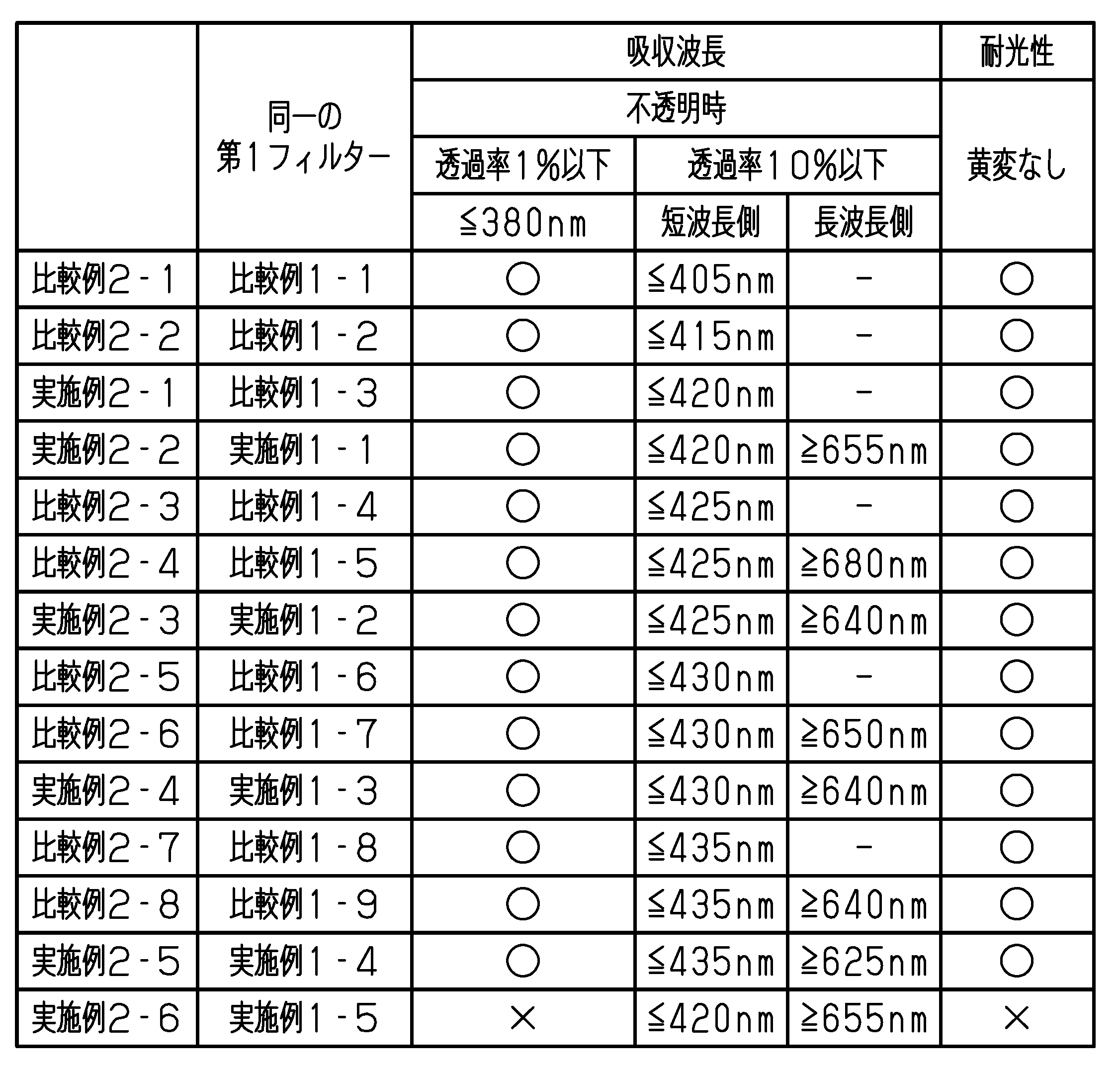
- Table 3 shows the wavelength range absorbed by each light control window and the light resistance of the light control window.
- the light control window of comparative example 2-1 does not have the first filter.
- the light control windows of Comparative Examples other than Comparative Example 2-1 and the light control windows of all Examples have the first filter.
- each reverse-type dimming window has a first filter that is the same as the first filter that one of the normal-type dimming windows described above has.
- the light control windows of Examples 2-1 to 2-5 and Comparative Examples 2-1 to 2-8 had a transmittance of 1% or less in the wavelength range of 380 nm or less. Admitted.
- the incidence of ultraviolet rays on the light control windows is suppressed, thereby preventing yellowing of the light control sheets. suppressed.
- the light control window of Example 2-1 the light control window of Comparative Example 2-1 was combined with a first filter that absorbs only the light in the wavelength region on the short wavelength side in the visible region.
- the light control window of Example 2-1 had a transmittance of 10% or less for light in the wavelength region on the short wavelength side in the visible region.
- the photochromatic window of Example 2-1 was observed to exhibit the transmittance spectrum shown in FIG. 8 by including a first filter exhibiting the transmittance spectrum shown in FIG.
- the light in the wavelength region on the short wavelength side in the visible region and the light in the wavelength region on the long wavelength side in the visible region was combined with a first filter that absorbs light in the wavelength range of .
- the transmittance of light in the short wavelength region in the visible region and light in the long wavelength region in the visible region is 10% or less. was found to be
- the light control window of Example 2-2 exhibited the transmittance spectrum shown in FIG. 10 by including the first filter showing the transmittance spectrum shown in FIG.
- the dimming window of Examples 2-3 was observed to exhibit the transmittance spectrum shown in FIG. 14 by including a first filter exhibiting the transmittance spectrum shown in FIG.
- the dimming windows of Examples 2-4 were observed to exhibit the transmittance spectra shown in FIG. 18 by including a first filter exhibiting the transmittance spectra shown in FIG.
- the dimming windows of Examples 2-5 were observed to exhibit the transmittance spectra shown in FIG. 22 by including a first filter exhibiting the transmittance spectra shown in FIG.
- the transmittance for light in the wavelength range of 420 nm or less the yellowness YI of the dimming window, the Y value of the dimming window, and the reflectance for light in the wavelength range of 420 nm or less are as follows. It was as shown in Table 4.
- the yellowness YI exceeds 10 regardless of the state of the light control window. Therefore, in the light control windows of Comparative Examples 2-3 to 2-8, when a visitor looks at the light control windows from indoors, they tend to perceive the light control windows to be tinged with yellow. In contrast, in the light control windows of Examples 2-1 to 2-6, the yellowness YI is 10 or less regardless of the state of the light control window. Therefore, with the light control windows of Examples 2-1 to 2-6, when the guest looks at the light control window from inside the room, the guest does not feel that the light control window is yellowish. be done.
- the Y value of the standard light directed from the outdoors to the indoors is 70% or more.
- the Y value of the standard light directed from the outside to the inside is less than 70% when the light control window is in the transparent state. Therefore, according to the light control windows of the light control windows of Examples 2-1 to 2-4 and 2-6, compared to the light control window of Example 2-5, the occupant can see the light control window from indoors. In this case, it is possible to prevent the resident from feeling that the dimming window is dark.
- reflection in the wavelength range of 420 nm or less of the light incident on the light control window from the outdoors rate is 10% or less. Therefore, it is possible to suppress the light reflected by the light control window from attracting insects to the light control window.
- the effects described below can be obtained.
- the transmittance of light in the wavelength range of 420 nm or less is 10% or less, so that insects are attracted to the surface of the light control window that is exposed to the outdoors. be suppressed.
- the Y value of the light transmitted from the outside to the inside through the light control window is 70% or more, when the person staying indoors visually recognizes the light control window, he/she feels that the light control window is dark. can be suppressed. In addition, it is possible to suppress the difficulty of visually recognizing the outdoors from indoors.
Landscapes
- Physics & Mathematics (AREA)
- Nonlinear Science (AREA)
- Chemical & Material Sciences (AREA)
- Crystallography & Structural Chemistry (AREA)
- General Physics & Mathematics (AREA)
- Optics & Photonics (AREA)
- Mathematical Physics (AREA)
- Engineering & Computer Science (AREA)
- Structural Engineering (AREA)
- Liquid Crystal (AREA)
- Geometry (AREA)
- Spectroscopy & Molecular Physics (AREA)
- Architecture (AREA)
- Civil Engineering (AREA)
- Optical Elements Other Than Lenses (AREA)
Abstract
Description
上記調光窓において、前記調光層が前記不透明状態であるときの前記黄色度YIから前記調光層が前記透明状態であるときの前記黄色度YIを減算した差分値が、0.2以下であってもよい。この調光窓によれば、黄色度YIの差分値が0.2以下であるから、調光層が呈する状態の違いによる調光窓の黄色みのばらつきを抑えることが可能である。
図1から図5を参照して、調光窓の構造を説明する。
図1が示すように、調光窓は、調光シート10と透明部材TMとを備えている。透明部材TMは、例えばソーダ石灰ガラスから形成される。なお、透明部材TMは、ソーダ石灰ガラスに限らず、ソーダ石灰ガラス以外のガラスから形成されてもよい。透明部材TMは、例えば、石英ガラス、ホウケイ酸ガラス、鉛ガラス、フッ化物ガラスなどから形成されてよい。透明部材TMは、合成樹脂から形成されてもよい。透明部材TMが合成樹脂から形成される場合には、透明部材TMは、調光シート10が貼り付けられる面に、ガスバリア層を備えることが好ましい。これにより、透明部材TMから放出されるガスが調光シート10に到達することが抑えられる。
調光窓の厚さ方向のうち、調光シート10から透明部材TMに向かう方向が、第1方向D1である。調光窓の厚さ方向のうち、透明部材TMから調光シート10に向かう方向が、第2方向D2である。調光シート10は、透明部材TMが備える一対の面のうち、建物の屋内に位置する面に貼り付けられる。そのため、第1方向D1は、調光窓を備える建物の屋内から屋外に向かう方向である。これに対して、第2方向D2は、調光窓を備える建物の屋外から屋内に向かう方向である。
図2が示すように、調光層12は、第1透明電極層21、第2透明電極層22、液晶層23、第1透明基材24、および、第2透明基材25を備えている。液晶層23は、調光層12の厚さ方向において、第1透明基材24と第2透明基材25との間に位置している。第1透明基材24は、第1透明電極層21を支持している。第2透明基材25は、第2透明電極層22を支持している。調光層12の厚さ方向において、液晶層23は、第1透明電極層21と第2透明電極層22との間に位置している。
なお、調光層12の型式は、上述したノーマル型に限らず、リバース型でもよい。すなわち、第1透明電極層21と第2透明電極層22との間に電圧が印加されていない状態において、調光層12が透明状態を有する。これに対して、第1透明電極層21と第2透明電極層22との間に電圧が印加された状態において、調光層12が不透明状態を有する。透明状態における調光層12のヘイズは、不透明状態における調光層12のヘイズよりも低い。
図5が示すように、調光層12は、第1透明電極層21、第2透明電極層22、液晶層23、第1透明基材24、および、第2透明基材25に加えて、第1配向層28と第2配向層29とを備えている。第1配向層28は、調光層12の厚さ方向において、第1透明電極層21と液晶層23との間に位置している。第2配向層29は、調光層12の厚さ方向において、第2透明電極層22と液晶層23との間に位置している。
なお、調光シート10は、上述した粘着層11および調光層12以外の他の機能層を備えてもよい。他の機能層は、例えば、紫外線吸収層およびハードコート層などであってよい。調光シート10が機能層を備える場合には、機能層は、第1透明基材24および第2透明基材25のうちで、粘着層11が位置しない透明基材上に位置してよい。
以下、本開示における調光窓の光学特性を説明する。
調光窓は、以下の条件1および条件2を満たす。
(条件2)第2方向D2に沿って調光窓を透過した標準光源D65の光において、JIS K 7373:2006に規定される黄色度YIが10以下である。
(条件6)第1方向D1に沿って調光窓に入射する620nm以上の波長域の光における透過率が、10%以下である。
条件3におけるY値は、JIS Z 8781‐1:2012「測色-第1部:CIE測色標準観測者の等色関数」に規定される計算方法によって算出される。条件6における透過率は全光線透過率であり、かつ、上述したJIS K 7361‐1:1997に準拠した方法によって測定される。
図6から図22、および、表1から表4を参照して、実施例および比較例を説明する。
なお、図6から図22のうち、図6、図8、図10、図12、図14、図16、図18、図20、および、図22は、それぞれ調光窓における透過率スペクトルを示している。透過率スペクトルにおける透過率は、全光線透過率である。各図において、ノーマル型調光窓が不透明状態であって、調光層に印加された電圧が0Vである場合のスペクトルが実線で示され、ノーマル型調光窓が透明状態であって、調光層に印加された電圧が40Vである場合のスペクトルが破線で示されている。また、リバース型調光窓が透明状態であって、調光層に印加された電圧が0Vである場合のスペクトルが一点鎖線で示され、リバース型調光窓が不透明状態であって、調光層に印加された電圧が40Vである場合のスペクトルが二点鎖線で示されている。
透明部材として、3mmの厚さを有したソーダ石灰ガラス製の板部材を準備した。また、調光シートとして、紫外線吸収剤を含む粘着層と、調光層とから構成されるノーマル型の調光シートを準備した。なお、調光層として、液晶層、一対の透明電極層、一対の透明基材、紫外線吸収層、および、ハードコート層を備える調光層を準備した。透明基材のうち、一方の透明基材を粘着層によって透明部材に貼り付け、かつ、他方の透明基材上に上述した紫外線吸収層を積層し、紫外線吸収層上にハードコート層を積層した。

透明部材として、3mmの厚さを有したソーダ石灰ガラス製の板部材を準備した。また、調光シートとして、紫外線吸収剤を含む粘着層と、調光層とから構成されるリバース型の調光シートを準備した。なお、調光層として、液晶層、一対の配向層、一対の透明電極層、一対の透明基材、紫外線吸収層、および、ハードコート層を備える調光層を準備した。透明基材のうち、一方の透明基材を粘着層によって透明部材に貼り付け、かつ、他方の透明基材上に上述した紫外線吸収層を積層し、紫外線吸収層上にハードコート層を積層した。

(1)調光窓を通じて屋内から屋外に漏れる光のうち、420nm以下の波長域の光の透過率が10%以下であることによって、調光窓のうち、屋外に露出した面に虫が誘因されることが抑えられる。
11…粘着層
12…調光層
21…第1透明電極層
22…第2透明電極層
23…液晶層
24…第1透明基材
25…第2透明基材
26…第1フィルター
27…第2フィルター
28…第1配向層
29…第2配向層
TM…透明部材
Claims (9)
- 透明部材と、
前記透明部材に貼り付けられる調光シートと、を備える調光窓であって、
前記調光シートは、
前記透明部材に貼り付けられる粘着層と、
前記粘着層によって前記透明部材に貼り付けられる調光層であって、前記調光層に対する電圧の印加の有無に応じて透明状態と不透明状態とを有する前記調光層と、を備え、
前記粘着層および前記調光層の少なくとも一方が、可視領域の光における一部を吸収するフィルターを含み、
前記調光シートから前記透明部材に向かう第1方向に沿って前記調光窓を透過する420nm以下の波長域の光における透過率が10%以下であり、かつ、
前記透明部材から前記調光シートに向かう第2方向に沿って前記調光窓を透過した標準光源D65の光において、JIS K 7373:2006に規定される黄色度YIが10以下である
調光窓。 - 前記調光層が前記透明状態であるとき、前記第2方向に沿って前記調光窓を透過した前記標準光源D65の光において、JIS Z 8781‐1:2012に規定されるY値が70%以上である
請求項1に記載の調光窓。 - 前記粘着層は、紫外線吸収層を含み、
前記第2方向に沿って前記調光窓を透過する380nm以下の波長域の光における透過率が1%以下である
請求項1または2に記載の調光窓。 - 前記調光層が前記透明状態であるとき、および、前記不透明状態であるときの両方において、
前記第1方向に沿って前記調光窓に入射する420nm以下の波長域の光における反射率が、10%以下である
請求項1から3のいずれか一項に記載の調光窓。 - 前記透明部材は、ソーダ石灰ガラスから形成される
請求項1から4のいずれか一項に記載の調光窓。 - 前記調光層が前記不透明状態であるときの前記黄色度YIから前記調光層が前記透明状態であるときの前記黄色度YIを減算した差分値が、0.2以下である
請求項1から5のいずれか一項に記載の調光窓。 - 前記第1方向に沿って前記調光窓に入射する620nm以上の波長域の光における透過率が、10%以下である
請求項1から6のいずれか一項に記載の調光窓。 - 前記粘着層が、前記フィルターである
請求項1から7のいずれか一項に記載の調光窓。 - 前記調光層は、第1透明電極層と、第2透明電極層と、前記第1透明電極層と前記第2透明電極層との間に位置する液晶層と、を備え、
前記液晶層が、前記フィルターである
請求項1から7のいずれか一項に記載の調光窓
Priority Applications (4)
| Application Number | Priority Date | Filing Date | Title |
|---|---|---|---|
| EP22867464.4A EP4403988A4 (en) | 2021-09-13 | 2022-09-12 | LIGHT CONTROL WINDOW |
| JP2023547025A JP7563618B2 (ja) | 2021-09-13 | 2022-09-12 | 調光窓 |
| CN202280053224.1A CN117751319A (zh) | 2021-09-13 | 2022-09-12 | 调光窗 |
| US18/602,605 US12282229B2 (en) | 2021-09-13 | 2024-03-12 | Light control window |
Applications Claiming Priority (2)
| Application Number | Priority Date | Filing Date | Title |
|---|---|---|---|
| JP2021148695 | 2021-09-13 | ||
| JP2021-148695 | 2021-09-13 |
Related Child Applications (1)
| Application Number | Title | Priority Date | Filing Date |
|---|---|---|---|
| US18/602,605 Continuation US12282229B2 (en) | 2021-09-13 | 2024-03-12 | Light control window |
Publications (1)
| Publication Number | Publication Date |
|---|---|
| WO2023038143A1 true WO2023038143A1 (ja) | 2023-03-16 |
Family
ID=85506501
Family Applications (1)
| Application Number | Title | Priority Date | Filing Date |
|---|---|---|---|
| PCT/JP2022/034119 Ceased WO2023038143A1 (ja) | 2021-09-13 | 2022-09-12 | 調光窓 |
Country Status (6)
| Country | Link |
|---|---|
| US (1) | US12282229B2 (ja) |
| EP (1) | EP4403988A4 (ja) |
| JP (1) | JP7563618B2 (ja) |
| CN (1) | CN117751319A (ja) |
| TW (1) | TW202319823A (ja) |
| WO (1) | WO2023038143A1 (ja) |
Citations (5)
| Publication number | Priority date | Publication date | Assignee | Title |
|---|---|---|---|---|
| JP2006330100A (ja) * | 2005-05-23 | 2006-12-07 | Asahi Glass Co Ltd | 調光装置及びその製造方法 |
| JP2018050639A (ja) * | 2017-12-25 | 2018-04-05 | 大成ファインケミカル株式会社 | 害虫誘引阻止シート |
| JP2019515841A (ja) * | 2016-03-17 | 2019-06-13 | サン−ゴバン グラス フランス | 電気的に制御可能なサンバイザを備えたウインドシールド |
| JP2019132927A (ja) * | 2018-01-30 | 2019-08-08 | 凸版印刷株式会社 | 調光フィルム、調光デバイスおよび調光装置 |
| JP2020519952A (ja) * | 2017-05-09 | 2020-07-02 | メルク・パテント・ゲゼルシヤフト・ミツト・ベシユレンクテル・ハフツングMerck Patent GmbH | スイッチャブル層および少なくとも1つの光学層を有する光学デバイス |
Family Cites Families (3)
| Publication number | Priority date | Publication date | Assignee | Title |
|---|---|---|---|---|
| JP2019045612A (ja) | 2017-08-31 | 2019-03-22 | 凸版印刷株式会社 | 調光フィルム、及びそれを用いた調光装置 |
| JP7187947B2 (ja) * | 2018-09-28 | 2022-12-13 | 凸版印刷株式会社 | 調光シート、および、調光ガラス |
| TW202208168A (zh) * | 2020-05-01 | 2022-03-01 | 美商康寧公司 | 具減少的斑紋之不對稱液晶面板、隔熱玻璃單元及結合其之窗 |
-
2022
- 2022-09-12 WO PCT/JP2022/034119 patent/WO2023038143A1/ja not_active Ceased
- 2022-09-12 CN CN202280053224.1A patent/CN117751319A/zh active Pending
- 2022-09-12 JP JP2023547025A patent/JP7563618B2/ja active Active
- 2022-09-12 EP EP22867464.4A patent/EP4403988A4/en active Pending
- 2022-09-13 TW TW111134454A patent/TW202319823A/zh unknown
-
2024
- 2024-03-12 US US18/602,605 patent/US12282229B2/en active Active
Patent Citations (5)
| Publication number | Priority date | Publication date | Assignee | Title |
|---|---|---|---|---|
| JP2006330100A (ja) * | 2005-05-23 | 2006-12-07 | Asahi Glass Co Ltd | 調光装置及びその製造方法 |
| JP2019515841A (ja) * | 2016-03-17 | 2019-06-13 | サン−ゴバン グラス フランス | 電気的に制御可能なサンバイザを備えたウインドシールド |
| JP2020519952A (ja) * | 2017-05-09 | 2020-07-02 | メルク・パテント・ゲゼルシヤフト・ミツト・ベシユレンクテル・ハフツングMerck Patent GmbH | スイッチャブル層および少なくとも1つの光学層を有する光学デバイス |
| JP2018050639A (ja) * | 2017-12-25 | 2018-04-05 | 大成ファインケミカル株式会社 | 害虫誘引阻止シート |
| JP2019132927A (ja) * | 2018-01-30 | 2019-08-08 | 凸版印刷株式会社 | 調光フィルム、調光デバイスおよび調光装置 |
Non-Patent Citations (1)
| Title |
|---|
| See also references of EP4403988A4 * |
Also Published As
| Publication number | Publication date |
|---|---|
| JPWO2023038143A1 (ja) | 2023-03-16 |
| EP4403988A4 (en) | 2025-01-08 |
| EP4403988A1 (en) | 2024-07-24 |
| CN117751319A (zh) | 2024-03-22 |
| JP7563618B2 (ja) | 2024-10-08 |
| US12282229B2 (en) | 2025-04-22 |
| US20240219778A1 (en) | 2024-07-04 |
| TW202319823A (zh) | 2023-05-16 |
Similar Documents
| Publication | Publication Date | Title |
|---|---|---|
| US9946147B2 (en) | Transmission-type transparent screen, image display system and image display method | |
| JP7192829B2 (ja) | 映像表示透明部材、映像表示システムおよび映像表示方法 | |
| JP6120481B2 (ja) | 光制御フィルム及び多層光学フィルムスタック | |
| KR102127226B1 (ko) | 스위칭가능한 유리 구조물 및 차량 창문 | |
| JP6736958B2 (ja) | 透過型透明スクリーン、映像表示システムおよび映像表示方法 | |
| JP2002527326A (ja) | 熱互変機器 | |
| TW201628991A (zh) | 調光窗 | |
| CN102216817A (zh) | 可变透射复合干涉滤光器 | |
| CN109073803A (zh) | 光学体、窗材料及卷帘 | |
| JP2020052374A (ja) | 調光シート、および、調光ガラス | |
| CN108269500A (zh) | 一种显示面板及其制造方法 | |
| US7459641B2 (en) | Optical filtering and electromagnetic armouring structure | |
| KR20180132704A (ko) | 광학체 및 유리재 | |
| JP2015174406A (ja) | 窓貼用赤外線遮断フイルム | |
| EP2994590A1 (en) | Composite transparent lighting device | |
| WO2023038143A1 (ja) | 調光窓 | |
| US20240027818A1 (en) | Ir stable and uv stable switchable panel and methods for making and using | |
| US11180005B2 (en) | Systems with windows | |
| WO2025017452A1 (en) | Luminois laminated glazing with enhanced solar and ambient light performance | |
| US20250153462A1 (en) | Multilayer laminate | |
| CN114637064B (zh) | 一种滤蓝光膜及显示设备 | |
| CN110795962A (zh) | 光学指纹传感器模组及其形成方法 | |
| JP7711935B2 (ja) | 害虫誘引阻止材 | |
| KR20190080285A (ko) | 태양광의 차폐 성능을 개선하기 위한 광학 구조체 및 이의 제조 방법 | |
| KR101827722B1 (ko) | 광학 필름 및 이를 포함하는 표시 장치 |
Legal Events
| Date | Code | Title | Description |
|---|---|---|---|
| 121 | Ep: the epo has been informed by wipo that ep was designated in this application |
Ref document number: 22867464 Country of ref document: EP Kind code of ref document: A1 |
|
| WWE | Wipo information: entry into national phase |
Ref document number: 202280053224.1 Country of ref document: CN |
|
| WWE | Wipo information: entry into national phase |
Ref document number: 2023547025 Country of ref document: JP |
|
| WWE | Wipo information: entry into national phase |
Ref document number: 2022867464 Country of ref document: EP |
|
| NENP | Non-entry into the national phase |
Ref country code: DE |
|
| ENP | Entry into the national phase |
Ref document number: 2022867464 Country of ref document: EP Effective date: 20240415 |