WO2023042560A1 - 固体電解質材料およびそれを用いた電池 - Google Patents
固体電解質材料およびそれを用いた電池 Download PDFInfo
- Publication number
- WO2023042560A1 WO2023042560A1 PCT/JP2022/029612 JP2022029612W WO2023042560A1 WO 2023042560 A1 WO2023042560 A1 WO 2023042560A1 JP 2022029612 W JP2022029612 W JP 2022029612W WO 2023042560 A1 WO2023042560 A1 WO 2023042560A1
- Authority
- WO
- WIPO (PCT)
- Prior art keywords
- solid electrolyte
- electrolyte material
- material according
- negative electrode
- battery
- Prior art date
- Legal status (The legal status is an assumption and is not a legal conclusion. Google has not performed a legal analysis and makes no representation as to the accuracy of the status listed.)
- Ceased
Links
Images


Classifications
-
- H—ELECTRICITY
- H01—ELECTRIC ELEMENTS
- H01M—PROCESSES OR MEANS, e.g. BATTERIES, FOR THE DIRECT CONVERSION OF CHEMICAL ENERGY INTO ELECTRICAL ENERGY
- H01M10/00—Secondary cells; Manufacture thereof
- H01M10/05—Accumulators with non-aqueous electrolyte
- H01M10/056—Accumulators with non-aqueous electrolyte characterised by the materials used as electrolytes, e.g. mixed inorganic/organic electrolytes
- H01M10/0561—Accumulators with non-aqueous electrolyte characterised by the materials used as electrolytes, e.g. mixed inorganic/organic electrolytes the electrolyte being constituted of inorganic materials only
- H01M10/0562—Solid materials
-
- C—CHEMISTRY; METALLURGY
- C01—INORGANIC CHEMISTRY
- C01G—COMPOUNDS CONTAINING METALS NOT COVERED BY SUBCLASSES C01D OR C01F
- C01G23/00—Compounds of titanium
- C01G23/002—Compounds containing titanium, with or without oxygen or hydrogen, and containing two or more other elements
-
- H—ELECTRICITY
- H01—ELECTRIC ELEMENTS
- H01B—CABLES; CONDUCTORS; INSULATORS; SELECTION OF MATERIALS FOR THEIR CONDUCTIVE, INSULATING OR DIELECTRIC PROPERTIES
- H01B1/00—Conductors or conductive bodies characterised by the conductive materials; Selection of materials as conductors
- H01B1/06—Conductors or conductive bodies characterised by the conductive materials; Selection of materials as conductors mainly consisting of other non-metallic substances
-
- H—ELECTRICITY
- H01—ELECTRIC ELEMENTS
- H01B—CABLES; CONDUCTORS; INSULATORS; SELECTION OF MATERIALS FOR THEIR CONDUCTIVE, INSULATING OR DIELECTRIC PROPERTIES
- H01B13/00—Apparatus or processes specially adapted for manufacturing conductors or cables
-
- H—ELECTRICITY
- H01—ELECTRIC ELEMENTS
- H01M—PROCESSES OR MEANS, e.g. BATTERIES, FOR THE DIRECT CONVERSION OF CHEMICAL ENERGY INTO ELECTRICAL ENERGY
- H01M10/00—Secondary cells; Manufacture thereof
- H01M10/05—Accumulators with non-aqueous electrolyte
- H01M10/052—Li-accumulators
-
- H—ELECTRICITY
- H01—ELECTRIC ELEMENTS
- H01M—PROCESSES OR MEANS, e.g. BATTERIES, FOR THE DIRECT CONVERSION OF CHEMICAL ENERGY INTO ELECTRICAL ENERGY
- H01M4/00—Electrodes
- H01M4/02—Electrodes composed of, or comprising, active material
- H01M4/62—Selection of inactive substances as ingredients for active masses, e.g. binders, fillers
-
- C—CHEMISTRY; METALLURGY
- C01—INORGANIC CHEMISTRY
- C01P—INDEXING SCHEME RELATING TO STRUCTURAL AND PHYSICAL ASPECTS OF SOLID INORGANIC COMPOUNDS
- C01P2006/00—Physical properties of inorganic compounds
- C01P2006/12—Surface area
-
- C—CHEMISTRY; METALLURGY
- C01—INORGANIC CHEMISTRY
- C01P—INDEXING SCHEME RELATING TO STRUCTURAL AND PHYSICAL ASPECTS OF SOLID INORGANIC COMPOUNDS
- C01P2006/00—Physical properties of inorganic compounds
- C01P2006/40—Electric properties
-
- H—ELECTRICITY
- H01—ELECTRIC ELEMENTS
- H01M—PROCESSES OR MEANS, e.g. BATTERIES, FOR THE DIRECT CONVERSION OF CHEMICAL ENERGY INTO ELECTRICAL ENERGY
- H01M2300/00—Electrolytes
- H01M2300/0017—Non-aqueous electrolytes
- H01M2300/0065—Solid electrolytes
- H01M2300/0068—Solid electrolytes inorganic
-
- H—ELECTRICITY
- H01—ELECTRIC ELEMENTS
- H01M—PROCESSES OR MEANS, e.g. BATTERIES, FOR THE DIRECT CONVERSION OF CHEMICAL ENERGY INTO ELECTRICAL ENERGY
- H01M2300/00—Electrolytes
- H01M2300/0017—Non-aqueous electrolytes
- H01M2300/0065—Solid electrolytes
- H01M2300/0068—Solid electrolytes inorganic
- H01M2300/008—Halides
-
- Y—GENERAL TAGGING OF NEW TECHNOLOGICAL DEVELOPMENTS; GENERAL TAGGING OF CROSS-SECTIONAL TECHNOLOGIES SPANNING OVER SEVERAL SECTIONS OF THE IPC; TECHNICAL SUBJECTS COVERED BY FORMER USPC CROSS-REFERENCE ART COLLECTIONS [XRACs] AND DIGESTS
- Y02—TECHNOLOGIES OR APPLICATIONS FOR MITIGATION OR ADAPTATION AGAINST CLIMATE CHANGE
- Y02E—REDUCTION OF GREENHOUSE GAS [GHG] EMISSIONS, RELATED TO ENERGY GENERATION, TRANSMISSION OR DISTRIBUTION
- Y02E60/00—Enabling technologies; Technologies with a potential or indirect contribution to GHG emissions mitigation
- Y02E60/10—Energy storage using batteries
Definitions
- the present disclosure relates to solid electrolyte materials and batteries using the same.
- Patent Document 1 discloses an all-solid battery using a sulfide solid electrolyte.
- Patent Document 2 discloses LiBF 4 as a fluoride solid electrolyte material.
- An object of the present disclosure is to provide a solid electrolyte material that is suitable for lithium ion conduction and has improved contact with other materials.
- the solid electrolyte material of the present disclosure is A solid electrolyte material comprising Li, Ti, Al, and F,
- the solid electrolyte material has a specific surface area of 5.7 m 2 /g or more.
- the present disclosure provides a solid electrolyte material that is suitable for lithium ion conduction and has improved contact with other materials.
- FIG. 1 shows a cross-sectional view of a battery 1000 according to a second embodiment.
- FIG. 2 shows a schematic diagram of a pressure forming die 300 used to evaluate the ionic conductivity of solid electrolyte materials.
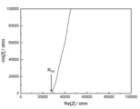
- 3 is a graph showing a Cole-Cole plot obtained by impedance measurement of the solid electrolyte material according to Example 1.
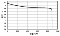
- FIG. 4 is a graph showing the initial discharge characteristics of the batteries according to Example 1 and Comparative Example 1;
- the solid electrolyte material according to the first embodiment contains Li, Ti, Al, and F.
- the specific surface area of the solid electrolyte material according to the first embodiment is 5.7 m 2 /g or more.
- the specific surface area of the solid electrolyte material in the present disclosure means the specific surface area determined by the BET method.
- the solid electrolyte material according to the first embodiment is suitable for lithium ion conduction and has good contact with other materials. Therefore, the solid electrolyte material according to the first embodiment can reduce interface resistance with other materials.
- Another material is, for example, an active material.
- polycrystalline materials are used as active materials for lithium-ion secondary batteries.
- the surface of the active material is not flat and often has irregularities such as small grooves or depressions.
- the solid electrolyte in all-solid-state batteries, it is desired to improve the contact between the active material and the solid electrolyte in order to reduce the resistance of the battery.
- the solid electrolyte must be deformed by compression or the like according to the uneven shape of the active material.
- the pressure during pressing concentrates on the protrusions on the surface of the active material, and good contact with the inside of the recesses cannot be obtained.
- a small particle size or uneven surface means a large specific surface area. That is, a solid electrolyte with a large specific surface area tends to achieve good contact with the active material. As a result, the resistance of the battery can be reduced and, for example, the charge/discharge characteristics of the battery can be improved.
- the solid electrolyte material according to the first embodiment can be used, for example, to obtain batteries with excellent charge/discharge characteristics.
- An example of such a battery is an all solid state battery.
- the all-solid-state battery may be a primary battery or a secondary battery.
- the solid electrolyte material according to the first embodiment desirably does not contain sulfur.
- a sulfur-free solid electrolyte material does not generate hydrogen sulfide even when exposed to the atmosphere, and is therefore excellent in safety.
- the sulfide solid electrolyte disclosed in Patent Document 1 can generate hydrogen sulfide when exposed to the atmosphere.
- the solid electrolyte material according to the first embodiment contains F, it can have high oxidation resistance. This is because F has a high redox potential. On the other hand, since F has high electronegativity, it has a relatively strong bond with Li. As a result, solid electrolyte materials containing Li and F typically have low lithium ion conductivity. For example, LiBF 4 disclosed in Patent Document 2 has a low ionic conductivity of 6.67 ⁇ 10 ⁇ 9 S/cm. On the other hand, the solid electrolyte material according to the first embodiment can have an ionic conductivity of, for example, 7 ⁇ 10 ⁇ 9 S/cm or more by containing Ti and Al in addition to Li and F. That is, the solid electrolyte material according to the first embodiment is suitable for lithium ion conduction.
- the specific surface area of the solid electrolyte material according to the first embodiment may be less than 100 m 2 /g, 60 m 2 /g or less, or 53.38 m 2 /g or less.
- the specific surface area of the solid electrolyte material according to the first embodiment may be 8.3 m 2 /g or more, or may be 8.32 m 2 /g or more.
- the solid electrolyte material according to the first embodiment may further contain anions other than F.
- anions other than F examples of such anions are Cl, Br, I, O or Se.
- the ratio of the amount of F to the total amount of anions constituting the solid electrolyte material according to the first embodiment is 0.50 or more and 1.0 or less. good too.
- F may be the only anion constituting the solid electrolyte material according to the first embodiment. That is, the ratio of the amounts of substances may be 1.0.
- the solid electrolyte material according to the first embodiment may consist essentially of Li, Ti, Al, and F.
- the solid electrolyte material according to the first embodiment consists essentially of Li, Ti, Al, and F
- the total amount of all elements constituting the solid electrolyte material according to the first embodiment to the total amount of Li, Ti, Al, and F (ie, mole fraction) is 90% or more.
- the ratio (ie, mole fraction) may be 95% or greater.
- the solid electrolyte material according to the first embodiment may consist of Li, Ti, Al, and F only.
- the solid electrolyte material according to the first embodiment may further contain Zr.
- the solid electrolyte material according to the first embodiment may consist essentially of Li, Ti, Zr, Al, and F.
- the solid electrolyte material according to the first embodiment consists essentially of Li, Ti, Zr, Al, and F
- the substance amount of all elements constituting the solid electrolyte material according to the first embodiment means that the ratio of the total amount of substances of Li, Ti, Zr, Al, and F (that is, the molar fraction) to the total of is 90% or more.
- the ratio (ie, mole fraction) may be 95% or greater.
- the solid electrolyte material according to the first embodiment may consist of Li, Ti, Zr, Al, and F only.
- the solid electrolyte material according to the first embodiment may contain elements that are unavoidably mixed. Examples of such elements are hydrogen, oxygen or nitrogen. Such elements can be present in the raw powder of the solid electrolyte material or in the atmosphere for manufacturing or storing the solid electrolyte material.
- the ratio of the amount of Li substance to the total amount of Ti and Al is 1.12 or more and 5.07 or less. There may be.
- the ratio of the amount of Li to the sum of the amounts of Ti, Zr, and Al may be 1.12 or more and 5.07 or less.
- the solid electrolyte material according to the first embodiment may be a material represented by the following compositional formula (1).
- 0 ⁇ x ⁇ 1 and 0 ⁇ b ⁇ 1.5 are satisfied.
- a solid electrolyte material having such a composition has high ionic conductivity.
- the upper and lower limits of the range of x in formula (1) are 0.01, 0.2, 0.4, 0.5, 0.5, 0.7, 0.8, 0.95, and 0 It can be defined by any combination of numbers selected from 0.99.
- 0.7 ⁇ b ⁇ 1.3 may be satisfied, and 0.9 ⁇ b ⁇ 1.04 may be satisfied in formula (1).
- the upper and lower limits of the range of b in formula (1) are 0.7, 0.8, 0.9, 0.96, 1, 1.04, 1.1, 1.2, and 1.3. can be defined by any combination selected from the numerical values of
- the solid electrolyte material according to the first embodiment may be Li2.7Ti0.3Al0.7F6 .
- the solid electrolyte material according to the first embodiment may be a material represented by the following compositional formula (2).
- 0 ⁇ x ⁇ 1, 0 ⁇ y ⁇ 1, 0 ⁇ x+y ⁇ 1 and 0 ⁇ b ⁇ 1.5 are satisfied.
- a solid electrolyte material having such a composition has high ionic conductivity.
- the upper and lower limits of the range of x in equation (2) are 0.01, 0.2, 0.4, 0.5, 0.5, 0.7, 0.8, 0.95, and 0 It can be defined by any combination of numbers selected from 0.99.
- the upper and lower limits of the range of y in formula (2) are 0.01, 0.1, 0.15, 0.2, 0.4, 0.5, 0.5, 0.7, 0.01, 0.1, 0.15, 0.2, 0.4, 0.5, 0.5, 0.7, 0.00. It can be defined by any combination selected from the numbers 8, 0.95, and 0.99.
- the upper and lower limits of the range of b in formula (2) are 0.7, 0.8, 0.9, 0.96, 1, 1.04, 1.1, 1.2, and 1.3. can be defined by any combination selected from the numerical values of
- the solid electrolyte material according to the first embodiment may be Li2.7Ti0.1Zr0.2Al0.7F6 , Li2.7Ti0.2Zr0.1Al0.7F6 , or Li2.8Ti0.05Zr0.15Al0.8F6 .
- the solid electrolyte material according to the first embodiment may be crystalline or amorphous.
- the solid electrolyte material according to the first embodiment may contain a crystal phase represented by formula (1) or formula (2).
- the shape of the solid electrolyte material according to the first embodiment is not limited. Examples of such shapes are acicular, spherical, or ellipsoidal.
- the solid electrolyte material according to the first embodiment may be particles.
- the solid electrolyte material according to the first embodiment may have the shape of pellets or plates.
- the solid electrolyte material according to the first embodiment is produced, for example, by the following method.
- a plurality of raw material powders of halides weighed so as to have the desired composition and an organic solvent are mixed while pulverizing in a mixing device.
- the desired composition is Li2.7Ti0.3Al0.7F6 , LiF, TiF4 , and AlF3 are provided in molar ratios of the order of 2.7:0.3:0.7.
- Raw material powders may be prepared in pre-adjusted molar ratios to compensate for possible compositional changes in the synthesis process.
- the raw material powder and the organic solvent are put into a mixing device such as a planetary ball mill, and mixed while pulverizing. That is, a treatment using a wet ball mill is performed.
- the raw material powder may be mixed before being charged into the mixing device.
- the solid matter obtained by drying the slurry can be expected to have a smaller particle size by dissolving and recrystallizing it in an organic solvent.
- the raw material powder of the solid electrolyte material may be dissolved in an organic solvent and recrystallized to reduce the particle size, and then treated with a wet ball mill.
- the solid obtained by drying the slurry may be fired in vacuum or in an inert atmosphere. Firing is performed at, for example, 100° C. or higher and 300° C. or lower for 1 hour or longer. In order to suppress composition change during firing, firing may be performed in a sealed container such as a quartz tube.
- the solid electrolyte material according to the first embodiment is obtained by performing wet pulverization for pulverizing the mixture containing the raw material composition containing the constituent components of the solid electrolyte material and the solvent.
- the grain size of the balls used in the wet ball mill may be reduced.
- the amount of balls used in the wet ball mill may be increased.
- the wet ball mill treatment time may be lengthened.
- the solvent used in the wet ball mill may contain at least one selected from the group consisting of ⁇ -butyrolactone, propylene carbonate, butyl acetate, and tetralin. From the perspective of the dielectric constant of the solvent, N-methyl-2-pyrrolidone (NMP) may be used as the solvent.
- NMP N-methyl-2-pyrrolidone
- a battery according to the second embodiment includes a positive electrode, an electrolyte layer, and a negative electrode.
- the electrolyte layer is provided between the positive electrode and the negative electrode.
- At least one selected from the group consisting of the positive electrode, the electrolyte layer, and the negative electrode contains the solid electrolyte material according to the first embodiment.
- the battery according to the second embodiment contains the solid electrolyte material according to the first embodiment, it has excellent charge/discharge characteristics.
- FIG. 1 shows a cross-sectional view of a battery 1000 according to the second embodiment.
- a battery 1000 according to the second embodiment includes a positive electrode 201 , an electrolyte layer 202 and a negative electrode 203 .
- Electrolyte layer 202 is provided between positive electrode 201 and negative electrode 203 .
- a positive electrode 201 contains a positive electrode active material 204 and a solid electrolyte 100 .
- the electrolyte layer 202 contains an electrolyte material.
- the negative electrode 203 contains a negative electrode active material 205 and a solid electrolyte 100 .
- the solid electrolyte 100 includes, for example, the solid electrolyte material according to the first embodiment.
- the solid electrolyte 100 may be particles containing the solid electrolyte material according to the first embodiment as a main component.
- a particle containing the solid electrolyte material according to the first embodiment as a main component means a particle in which the component contained in the largest molar ratio is the solid electrolyte material according to the first embodiment.
- the solid electrolyte 100 may be particles made of the solid electrolyte material according to the first embodiment.
- the positive electrode 201 contains a material that can occlude and release metal ions (eg, lithium ions).
- the material is, for example, the positive electrode active material 204 .
- cathode active material 204 examples include lithium-containing transition metal oxides, transition metal fluorides, polyanions, fluorinated polyanion materials, transition metal sulfides, transition metal oxyfluorides, transition metal oxysulfides, or transition metal oxynitrides. be.
- lithium-containing transition metal oxides are Li(Ni,Co,Mn) O2 , Li(Ni,Co,Al) O2 or LiCoO2 .
- (A, B, C) means "at least one selected from the group consisting of A, B, and C.”
- the shape of the positive electrode active material 204 is not limited to a specific shape.
- the cathode active material 204 may be particles.
- the positive electrode active material 204 may have a median diameter of 0.1 ⁇ m or more and 100 ⁇ m or less.
- positive electrode active material 204 and solid electrolyte 100 can be well dispersed in positive electrode 201 . Thereby, the charge/discharge characteristics of the battery 1000 are improved.
- the positive electrode active material 204 has a median diameter of 100 ⁇ m or less, the diffusion rate of lithium in the positive electrode active material 204 is improved. This allows battery 1000 to operate at high output.
- the positive electrode active material 204 may have a larger median diameter than the solid electrolyte 100 . Thereby, the positive electrode active material 204 and the solid electrolyte 100 can be well dispersed in the positive electrode 201 .
- the ratio of the volume of the positive electrode active material 204 to the total volume of the positive electrode active material 204 and the volume of the solid electrolyte 100 is 0.30 or more and 0.95. It may be below.
- a coating layer may be formed on at least part of the surface of the positive electrode active material 204 .
- a coating layer can be formed on the surface of the positive electrode active material 204, for example, before mixing with the conductive aid and the binder.
- coating materials contained in the coating layer are sulfide solid electrolytes, oxide solid electrolytes or halide solid electrolytes.
- the coating material may contain the solid electrolyte material according to the first embodiment in order to suppress oxidative decomposition of the sulfide solid electrolyte.
- the coating material may contain an oxide solid electrolyte in order to suppress oxidative decomposition of the solid electrolyte material.
- Lithium niobate which has excellent stability at high potentials, may be used as the oxide solid electrolyte. By suppressing oxidative decomposition, an overvoltage rise of the battery 1000 can be suppressed.
- the positive electrode 201 may have a thickness of 10 ⁇ m or more and 500 ⁇ m or less.
- the electrolyte layer 202 contains an electrolyte material.
- the electrolyte material is, for example, a solid electrolyte material.
- the solid electrolyte material may include the solid electrolyte material according to the first embodiment.
- the electrolyte layer 202 may be a solid electrolyte layer.
- the electrolyte layer 202 may contain 50% by mass or more of the solid electrolyte material according to the first embodiment.
- the electrolyte layer 202 may contain 70% by mass or more of the solid electrolyte material according to the first embodiment.
- the electrolyte layer 202 may contain 90% by mass or more of the solid electrolyte material according to the first embodiment.
- the electrolyte layer 202 may consist only of the solid electrolyte material according to the first embodiment.
- the solid electrolyte material according to the first embodiment will be referred to as the first solid electrolyte material.
- a solid electrolyte material different from the first solid electrolyte material is referred to as a second solid electrolyte material.
- the electrolyte layer 202 may contain not only the first solid electrolyte material but also the second solid electrolyte material. In the electrolyte layer 202, the first solid electrolyte material and the second solid electrolyte material may be uniformly dispersed. A layer made of the first solid electrolyte material and a layer made of the second solid electrolyte material may be stacked along the stacking direction of battery 1000 .
- the battery according to the second embodiment may include the positive electrode 201, the second electrolyte layer, the first electrolyte layer, and the negative electrode 203 in this order.
- the solid electrolyte material contained in the first electrolyte layer may have a lower reduction potential than the solid electrolyte material contained in the second electrolyte layer.
- the solid electrolyte material contained in the second electrolyte layer can be used without being reduced.
- the charge/discharge efficiency of the battery 1000 can be improved.
- the first electrolyte layer may contain a sulfide solid electrolyte in order to suppress reductive decomposition of the solid electrolyte material.
- the second electrolyte layer may contain the first solid electrolyte material. Since the first solid electrolyte material has high oxidation resistance, it is possible to realize a battery with excellent charge/discharge characteristics.
- the electrolyte layer 202 may consist only of the second solid electrolyte material.
- the electrolyte layer 202 may have a thickness of 1 ⁇ m or more and 1000 ⁇ m or less. When the electrolyte layer 202 has a thickness of 1 ⁇ m or more, the short circuit between the positive electrode 201 and the negative electrode 203 is less likely to occur. If the electrolyte layer 202 has a thickness of 1000 ⁇ m or less, the battery 1000 can operate at high power.
- Examples of the second solid electrolyte material are Li2MgX4 , Li2FeX4 , Li(Al,Ga,In) X4 , Li3 ( Al ,Ga,In) X6 , or LiI.
- X is at least one selected from the group consisting of F, Cl, Br and I.
- the electrolyte layer 202 may have a thickness of 1 ⁇ m or more and 1000 ⁇ m or less.
- the negative electrode 203 contains a material capable of intercalating and deintercalating metal ions (eg, lithium ions).
- the material is, for example, the negative electrode active material 205 .
- Examples of the negative electrode active material 205 are metal materials, carbon materials, oxides, nitrides, tin compounds, or silicon compounds.
- the metallic material may be a single metal or an alloy.
- Examples of metallic materials are lithium metal or lithium alloys.
- Examples of carbon materials are natural graphite, coke, ungraphitized carbon, carbon fibers, spherical carbon, artificial graphite, or amorphous carbon. From the viewpoint of capacity density, suitable examples of negative electrode active materials are silicon (ie, Si), tin (ie, Sn), silicon compounds, or tin compounds.
- the negative electrode active material 205 may be selected in consideration of the reduction resistance of the solid electrolyte material contained in the negative electrode 203 .
- the negative electrode active material 205 may be a material capable of intercalating and deintercalating lithium ions at 0.27 V or higher with respect to lithium.
- examples of such negative electrode active materials are titanium oxide, indium metal, or lithium alloys.
- examples of titanium oxides are Li4Ti5O12 , LiTi2O4 , or TiO2 .
- the shape of the negative electrode active material 205 is not limited to a specific shape.
- the negative electrode active material 205 may be particles.
- the negative electrode active material 205 may have a median diameter of 0.1 ⁇ m or more and 100 ⁇ m or less.
- negative electrode active material 205 and solid electrolyte 100 can be well dispersed in negative electrode 203 . Thereby, the charge/discharge characteristics of the battery 1000 are improved.
- the negative electrode active material 205 has a median diameter of 100 ⁇ m or less, the diffusion rate of lithium in the negative electrode active material 205 is improved. This allows battery 1000 to operate at high output.
- the negative electrode active material 205 may have a larger median diameter than the solid electrolyte 100 . Thereby, the negative electrode active material 205 and the solid electrolyte 100 can be well dispersed in the negative electrode 203 .
- the ratio of the volume of the negative electrode active material 205 to the total volume of the negative electrode active material 205 and the volume of the solid electrolyte 100 is 0.30 or more and 0.95. It may be below.
- the negative electrode 203 may have a thickness of 10 ⁇ m or more and 500 ⁇ m or less.
- At least one selected from the group consisting of positive electrode 201, electrolyte layer 202, and negative electrode 203 contains a second solid electrolyte material for the purpose of enhancing ion conductivity, chemical stability, and electrochemical stability. may be
- the second solid electrolyte material may be a sulfide solid electrolyte.
- sulfide solid electrolytes are Li 2 SP 2 S 5 , Li 2 S-SiS 2 , Li 2 S-B 2 S 3 , Li 2 S-GeS 2 , Li 3.25 Ge 0.25 P 0.75 S 4 , or Li10GeP2S12 . _
- the negative electrode 203 may contain a sulfide solid electrolyte in order to suppress reductive decomposition of the solid electrolyte material.
- the contact of the first solid electrolyte material with the negative electrode active material can be suppressed. As a result, the internal resistance of battery 1000 can be reduced.
- the second solid electrolyte material may be an oxide solid electrolyte.
- oxide solid electrolytes are (i) NASICON-type solid electrolytes such as LiTi2 ( PO4 ) 3 or elemental substitutions thereof; (ii) perovskite-type solid electrolytes such as (LaLi) TiO3 ; (iii) LISICON -type solid electrolytes such as Li14ZnGe4O16 , Li4SiO4 , LiGeO4 or elemental substitutions thereof ; (iv) garnet- type solid electrolytes such as Li7La3Zr2O12 or its elemental substitutions, or ( v) Li3PO4 or its N substitutions, is.
- NASICON-type solid electrolytes such as LiTi2 ( PO4 ) 3 or elemental substitutions thereof
- perovskite-type solid electrolytes such as (LaLi) TiO3 ;
- LISICON -type solid electrolytes such as Li14ZnGe4O16 , Li4SiO4 , LiGeO4
- the second solid electrolyte material may be a halide solid electrolyte.
- halide solid electrolytes are Li2MgX4 , Li2FeX4 , Li(Al,Ga,In) X4 , Li3 ( Al ,Ga,In) X6 , or LiI.
- X is at least one selected from the group consisting of F, Cl, Br and I.
- halide solid electrolyte is the compound represented by LiaMebYcZ6 .
- Me is at least one selected from the group consisting of metal elements other than Li and Y and metalloid elements.
- Z is at least one selected from the group consisting of F, Cl, Br and I;
- m represents the valence of Me.
- Simetallic elements are B, Si, Ge, As, Sb, and Te.
- Metallic element means all elements contained in Groups 1 to 12 of the periodic table (excluding hydrogen), and all elements contained in Groups 13 to 16 of the periodic table (however, , B, Si, Ge, As, Sb, Te, C, N, P, O, S, and Se).
- Me is the group consisting of Mg, Ca, Sr, Ba, Zn, Sc, Al, Ga, Bi, Zr, Hf, Ti, Sn, Ta, and Nb to improve the ionic conductivity of the halide solid electrolyte. It may be at least one selected from.
- the halide solid electrolyte may be Li3YCl6 or Li3YBr6 .
- the second solid electrolyte material may be an organic polymer solid electrolyte.
- organic polymer solid electrolytes examples include polymeric compounds and lithium salt compounds.
- the polymer compound may have an ethylene oxide structure. Since a polymer compound having an ethylene oxide structure can contain a large amount of lithium salt, the ionic conductivity can be further increased.
- lithium salts are LiPF6 , LiBF4 , LiSbF6, LiAsF6 , LiSO3CF3 , LiN ( SO2CF3 ) 2 , LiN( SO2C2F5 ) 2 , LiN( SO2CF3 ) . ( SO2C4F9 ) , or LiC ( SO2CF3 )3 .
- One lithium salt selected from these may be used alone. Alternatively, a mixture of two or more lithium salts selected from these may be used.
- At least one selected from the group consisting of the positive electrode 201, the electrolyte layer 202, and the negative electrode 203 is composed of a non-aqueous electrolyte liquid, a gel electrolyte, or an ion in order to facilitate the transfer of lithium ions and improve the output characteristics of the battery. It may contain liquids.
- the non-aqueous electrolyte contains a non-aqueous solvent and a lithium salt dissolved in the non-aqueous solvent.
- non-aqueous solvents examples include cyclic carbonate solvents, chain carbonate solvents, cyclic ether solvents, chain ether solvents, cyclic ester solvents, chain ester solvents, or fluorine solvents.
- cyclic carbonate solvents are ethylene carbonate, propylene carbonate, or butylene carbonate.
- linear carbonate solvents are dimethyl carbonate, ethyl methyl carbonate, or diethyl carbonate.
- examples of cyclic ether solvents are tetrahydrofuran, 1,4-dioxane, or 1,3-dioxolane.
- Chain ether solvents are 1,2-dimethoxyethane or 1,2-diethoxyethane.
- An example of a cyclic ester solvent is ⁇ -butyrolactone.
- An example of a linear ester solvent is methyl acetate.
- fluorosolvents are fluoroethylene carbonate, methyl fluoropropionate, fluorobenzene, fluoroethyl methyl carbonate, or fluorodimethylene carbonate.
- One non-aqueous solvent selected from these may be used alone. Alternatively, a combination of two or more non-aqueous solvents selected from these may be used.
- lithium salts are LiPF6 , LiBF4 , LiSbF6, LiAsF6 , LiSO3CF3 , LiN ( SO2CF3 ) 2 , LiN( SO2C2F5 ) 2 , LiN( SO2CF3 ) . ( SO2C4F9 ) , or LiC ( SO2CF3 )3 .
- One lithium salt selected from these may be used alone. Alternatively, a mixture of two or more lithium salts selected from these may be used.
- the lithium salt concentration is, for example, in the range of 0.5 mol/L or more and 2 mol/L or less.
- a polymer material impregnated with a non-aqueous electrolyte can be used as the gel electrolyte.
- examples of polymeric materials are polyethylene oxide, polyacrylonitrile, polyvinylidene fluoride, polymethyl methacrylate, or polymers with ethylene oxide linkages.
- ionic liquids examples include (i) aliphatic chain quaternary salts such as tetraalkylammonium or tetraalkylphosphonium; (ii) aliphatic cyclic ammoniums such as pyrrolidiniums, morpholiniums, imidazoliniums, tetrahydropyrimidiniums, piperaziniums, or piperidiniums; or (iii) nitrogen-containing heteroatoms such as pyridiniums or imidazoliums ring aromatic cations, is.
- aliphatic chain quaternary salts such as tetraalkylammonium or tetraalkylphosphonium
- aliphatic cyclic ammoniums such as pyrrolidiniums, morpholiniums, imidazoliniums, tetrahydropyrimidiniums, piperaziniums, or piperidiniums
- nitrogen-containing heteroatoms such as pyridin
- Examples of anions contained in the ionic liquid are PF 6 ⁇ , BF 4 ⁇ , SbF 6 ⁇ , AsF 6 ⁇ , SO 3 CF 3 ⁇ , N(SO 2 CF 3 ) 2 ⁇ , N(SO 2 C 2 F 5 ) 2- , N ( SO2CF3 ) ( SO2C4F9 )- , or C( SO2CF3 ) 3- .
- the ionic liquid may contain a lithium salt.
- At least one selected from the group consisting of the positive electrode 201, the electrolyte layer 202, and the negative electrode 203 may contain a binder in order to improve adhesion between particles.
- binders include polyvinylidene fluoride, polytetrafluoroethylene, polyethylene, polypropylene, aramid resin, polyamide, polyimide, polyamideimide, polyacrylonitrile, polyacrylic acid, polyacrylic acid methyl ester, polyacrylic acid ethyl ester, Polyacrylic acid hexyl ester, polymethacrylic acid, polymethacrylic acid methyl ester, polymethacrylic acid ethyl ester, polymethacrylic acid hexyl ester, polyvinyl acetate, polyvinylpyrrolidone, polyether, polyether sulfone, hexafluoropolypropylene, styrene-butadiene rubber , or carboxymethyl cellulose.
- Copolymers can also be used as binders.
- binders are tetrafluoroethylene, hexafluoroethylene, hexafluoropropylene, perfluoroalkyl vinyl ethers, vinylidene fluoride, chlorotrifluoroethylene, ethylene, propylene, pentafluoropropylene, fluoromethyl vinyl ether, acrylic acid , and hexadiene.
- a mixture of two or more materials selected from these may be used as the binder.
- At least one selected from the positive electrode 201 and the negative electrode 203 may contain a conductive aid in order to improve electronic conductivity.
- Examples of conductive aids include (i) graphites such as natural or artificial graphite; (ii) carbon blacks such as acetylene black or ketjen black; (iii) conductive fibers such as carbon or metal fibers; (iv) carbon fluoride, (v) metal powders such as aluminum; (vi) conductive whiskers such as zinc oxide or potassium titanate; (vii) a conductive metal oxide such as titanium oxide, or (viii) a conductive polymeric compound such as polyaniline, polypyrrole, or polythiophene; is.
- the conductive aid (i) or (ii) may be used.
- Examples of the shape of the battery according to the second embodiment are coin-shaped, cylindrical, rectangular, sheet-shaped, button-shaped, flat-shaped, and laminated.
- a material for forming a positive electrode, a material for forming an electrolyte layer, and a material for forming a negative electrode are prepared, and the positive electrode, the electrolyte layer, and the negative electrode are arranged in this order by a known method. It may also be manufactured by making laminated laminates.
- the solid content ratio is calculated by ⁇ (mass of input raw material)/(mass of input raw material+mass of input solvent) ⁇ 100.
- a planetary ball mill was used for milling at 500 rpm for 12 hours. After milling, the balls were separated to obtain a slurry. The resulting slurry was dried at 200° C. for 1 hour under nitrogen flow using a mantle heater.
- a powder of the solid electrolyte material according to Example 1 was obtained by pulverizing the obtained solid material with a mortar.
- the solid electrolyte material according to Example 1 had a composition represented by Li2.7Ti0.3Al0.7F6 .
- FIG. 2 shows a schematic diagram of a pressure forming die 300 used to evaluate the ionic conductivity of solid electrolyte materials.
- the pressure forming die 300 had a punch upper part 301 , a frame mold 302 and a punch lower part 303 .
- the frame mold 302 was made of insulating polycarbonate.
- Punch top 301 and punch bottom 303 were made of electronically conductive stainless steel.
- the ionic conductivity of the solid electrolyte material according to Example 1 was evaluated by the following method.
- the inside of the pressure molding die 300 was filled with the powder of the solid electrolyte material according to Example 1. Inside the pressing die 300, a pressure of 400 MPa was applied to the solid electrolyte material according to Example 1 using the upper punch 301 and the lower punch 303. As shown in FIG.
- the upper punch 301 and lower punch 303 were connected to a potentiostat (BioLogic, VSP300) equipped with a frequency response analyzer.
- the punch upper part 301 was connected to the working electrode and the terminal for potential measurement.
- the punch bottom 303 was connected to the counter and reference electrodes.
- the impedance of the solid electrolyte material was measured by electrochemical impedance measurement at room temperature.
- FIG. 3 is a graph showing a Cole-Cole plot obtained by impedance measurement of the solid electrolyte material according to Example 1.
- the real value of the impedance at the measurement point where the absolute value of the phase of the complex impedance was the smallest was regarded as the resistance to ion conduction of the solid electrolyte material. See the arrow R SE shown in FIG. 3 for the real value.
- the ionic conductivity was calculated based on the following formula (3) using the resistance value.
- ⁇ (R SE ⁇ S/t) ⁇ 1 (3)
- ⁇ represents ionic conductivity.
- S represents the contact area of the solid electrolyte material with the punch upper part 301 . That is, S is equal to the cross-sectional area of the hollow portion of the frame mold 302 in FIG.
- R SE represents the resistance value of the solid electrolyte material in impedance measurement.
- t represents the thickness of the solid electrolyte material. That is, t represents the thickness of the layer formed from the solid electrolyte material powder 101 in FIG.
- BET specific surface area A specific surface area/pore distribution measuring device (BELSORP MINI X manufactured by Microtrack Bell) was used to measure the specific surface area.
- the specific surface area obtained using this apparatus is hereinafter referred to as the BET specific surface area.
- the solid electrolyte material powder (about 1 g) according to Example 1 was put into a dedicated test tube.
- vacuum drying was performed at 80°C for 1 hour.
- the weight of the test tube was measured from the difference between the weight of the test tube containing the sample after pretreatment and the weight of the test tube before the sample was added.
- the specific surface area of the solid electrolyte material according to Example 1 was 29.00 m 2 /g.
- Li 3 PS 4 (57.41 mg), the solid electrolyte material according to Example 1 (26 mg), and the positive electrode mixture (9.1 mg) were laminated in this order. was done.
- a pressure of 300 MPa was applied to the obtained laminate to form a first electrolyte layer, a second electrolyte layer, and a positive electrode. That is, the second electrolyte layer formed from the solid electrolyte material according to Example 1 was sandwiched between the first electrolyte layer and the positive electrode.
- the thicknesses of the first electrolyte layer and the second electrolyte layer were 450 ⁇ m and 150 ⁇ m, respectively.
- metal Li (thickness: 200 ⁇ m) was laminated on the first electrolyte layer.
- current collectors made of stainless steel were attached to the positive and negative electrodes, and current collecting leads were attached to the current collectors.
- Example 1 a battery according to Example 1 was obtained.
- (Charging and discharging test) 4 is a graph showing the initial discharge characteristics of the battery according to Example 1.
- FIG. Initial charge/discharge characteristics were measured by the following method.
- the battery according to Example 1 was placed in a constant temperature bath at 85°C.
- a cell according to Example 1 was charged at a current density of 67.6 ⁇ A/cm 2 until a voltage of 4.2 V was reached. This current density corresponds to a 0.05C rate.
- Example 1 The cell according to Example 1 was then discharged at a current density of 67.6 ⁇ A/cm 2 until a voltage of 2.5V was reached.
- the battery according to Example 1 had an initial discharge capacity of 891 ⁇ Ah.
- Example 2 to 14> (Preparation of solid electrolyte material)
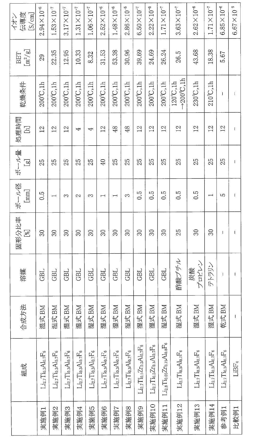
- Table 1 shows the solvent, solid content ratio, ball diameter, ball amount, treatment time, and drying conditions in the milling process.
- Solid electrolyte materials according to Examples 2 to 14 were obtained in the same manner as in Example 1 except for the conditions shown in Table 1.
- Example 2 A charge/discharge test was performed in the same manner as in Example 1 using the batteries according to Examples 2 to 14. As a result, the batteries according to Examples 2 to 14 were charged and discharged as well as the battery according to Example 1.
- the solid electrolyte material according to Reference Example 1 was produced by a dry ball mill without using an organic solvent.
- Example 1 Using the solid electrolyte material according to Reference Example 1, ionic conductivity and specific surface area were measured in the same manner as in Example 1.
- the ionic conductivity measured at 25° C. was 6.85 ⁇ 10 ⁇ 6 S/cm.
- the measured specific surface area was 5.67 m 2 /g.
- Example 1 The ionic conductivity was measured in the same manner as in Example 1 using LiBF 4 as the solid electrolyte material. As a result, the ionic conductivity measured at 25° C. was 6.67 ⁇ 10 ⁇ 9 S/cm.
- a battery according to Comparative Example 1 was obtained in the same manner as in Example 1, except that the solid electrolyte material according to Comparative Example 1 was used as the positive electrode mixture and the solid electrolyte used for the electrolyte layer.
- a charge/discharge test was performed in the same manner as in Example 1 using the battery according to Comparative Example 1.
- the initial discharge capacity of the battery according to Comparative Example 1 was 0.01 ⁇ Ah or less. That is, the battery according to Comparative Example 1 was neither charged nor discharged.
- the solid electrolyte materials according to Examples 1 to 14 have an ion conductivity of 7 ⁇ 10 ⁇ 9 S/cm or more and a specific surface area of 5.7 m 2 /g or more at room temperature.
- the specific surface area of the solid electrolyte material according to Reference Example 1 produced by a dry ball mill was a small value of 5.67 m 2 /g.
- the solid electrolyte material according to the present disclosure is suitable for providing batteries that have high lithium ion conductivity and can be charged and discharged well.
- the solid electrolyte material of the present disclosure is used, for example, in all-solid lithium ion secondary batteries.
Landscapes
- Chemical & Material Sciences (AREA)
- Manufacturing & Machinery (AREA)
- General Chemical & Material Sciences (AREA)
- Engineering & Computer Science (AREA)
- Chemical Kinetics & Catalysis (AREA)
- Electrochemistry (AREA)
- Inorganic Chemistry (AREA)
- Physics & Mathematics (AREA)
- Condensed Matter Physics & Semiconductors (AREA)
- General Physics & Mathematics (AREA)
- Organic Chemistry (AREA)
- General Life Sciences & Earth Sciences (AREA)
- Environmental & Geological Engineering (AREA)
- Life Sciences & Earth Sciences (AREA)
- Geology (AREA)
- Secondary Cells (AREA)
- Conductive Materials (AREA)
Abstract
Description
Li、Ti、Al、およびFを含む固体電解質材料であって、
前記固体電解質材料の比表面積が、5.7m2/g以上である。
第1実施形態による固体電解質材料は、Li、Ti、Al、およびFを含む。第1実施形態による固体電解質材料の比表面積は、5.7m2/g以上である。ここで、本開示における固体電解質材料の比表面積とは、BET法により求められる比表面積を意味する。
式(1)において、0<x<1、および、0<b≦1.5が充足される。このような組成を有する固体電解質材料は、高いイオン伝導度を有する。
式(2)において、0<x<1、0<y<1、0<x+y<1および、0<b≦1.5が充足される。このような組成を有する固体電解質材料は、高いイオン伝導度を有する。
第1実施形態による固体電解質材料は、例えば、下記の方法により製造される。
以下、第2実施形態が説明される。第1実施形態において説明された事項は、適宜、省略される。
(i)LiTi2(PO4)3またはその元素置換体のようなNASICON型固体電解質、
(ii)(LaLi)TiO3のようなペロブスカイト型固体電解質、
(iii)Li14ZnGe4O16、Li4SiO4、LiGeO4またはその元素置換体のようなLISICON型固体電解質、
(iv)Li7La3Zr2O12またはその元素置換体のようなガーネット型固体電解質
、または
(v)Li3PO4またはそのN置換体、
である。
(i)テトラアルキルアンモニウムまたはテトラアルキルホスホニウムのような脂肪族鎖状4級塩類、
(ii)ピロリジニウム類、モルホリニウム類、イミダゾリニウム類、テトラヒドロピリミジニウム類、ピペラジニウム類、またはピペリジニウム類のような脂肪族環状アンモニウム、または
(iii)ピリジニウム類またはイミダゾリウム類のような含窒素ヘテロ環芳香族カチオン、
である。
(i)天然黒鉛または人造黒鉛のようなグラファイト類、
(ii)アセチレンブラックまたはケッチェンブラックのようなカーボンブラック類、
(iii)炭素繊維または金属繊維のような導電性繊維類、
(iv)フッ化カーボン、
(v)アルミニウムのような金属粉末類、
(vi)酸化亜鉛またはチタン酸カリウムのような導電性ウィスカー類、
(vii)酸化チタンのような導電性金属酸化物、または
(viii)ポリアニリン、ポリピロール、またはポリチオフェンのような導電性高分子化合物、
である。低コスト化のために、上記(i)または(ii)の導電助剤が使用されてもよい。
(固体電解質材料の作製)
-60℃以下の露点を有するアルゴン雰囲気(以下、「乾燥アルゴン雰囲気」という)中で、原料粉としてLiF、TiF4、およびAlF3が、LiF:TiF4:AlF3=2.7:0.3:0.7のモル比となるように用意された。これらの原料紛は、0.5mmΦのボール(25g)とともに、45ccの遊星型ボールミル用のポッドに投入された。当該ポッドに、有機溶媒としてγ-ブチロラクトン(GBL)を固形分比率が50%となるように滴下した。ここで、固形分比率とは、{(投入原料の質量)/(投入原料の質量+投入溶媒の質量)}×100で算出される。遊星型ボールミルを用い、12時間、500rpmでミリング処理した。ミリング処理後、ボールを分離してスラリーが得られた。得られたスラリーを、マントルヒーターを用いて、窒素フロー下、200℃で1時間、乾燥した。得られた固体物を乳鉢で粉砕することによって、実施例1による固体電解質材料の粉末が得られた。実施例1による固体電解質材料は、Li2.7Ti0.3Al0.7F6により表される組成を有していた。
図2は、固体電解質材料のイオン伝導度を評価するために用いられた加圧成形ダイス300の模式図を示す。
ここで、σは、イオン伝導度を表す。Sは、固体電解質材料のパンチ上部301との接触面積を表す。すなわち、Sは、図3において、枠型302の中空部の断面積に等しい。RSEは、インピーダンス測定における固体電解質材料の抵抗値を表す。tは、固体電解質材料の厚みを表す。すなわち、tは、図3において、固体電解質材料の粉末101から形成される層の厚みを表す。
比表面積の測定には、比表面積/細孔分布測定装置(マイクロトラックベル社製、BELSORP MINI X)を用いた。以下、この装置を用いて得られた比表面積を、BET比表面積と記載する。
乾燥アルゴン雰囲気中で、実施例1による固体電解質材料および活物質であるLiCoO2が、30:70の体積比率となるように用意された。これらの材料がメノウ乳鉢中で混合された。このようにして、正極混合物が得られた。
図4は、実施例1による電池の初期放電特性を示すグラフである。初期充放電特性は、下記の方法により測定された。
(固体電解質材料の作製)
実施例2から8、12から14においては、原料粉としてLiF、TiF4、およびAlF3が、LiF:TiF4:AlF3=2.7:0.3:0.7のモル比となるように用意された。
実施例2から14による固体電解質材料のイオン伝導度は、実施例1と同様に測定された。測定結果は、表1に示される。
実施例2から14による固体電解質材料を用いて、実施例1と同様にして、BET比表面積が測定された。測定結果は、表1に示される。
実施例2から14による固体電解質材料を用いて、実施例1と同様にして、実施例2から14による電池が得られた。
乾燥アルゴン雰囲気中で、原料粉としてLiF、TiF4、およびAlF3が、LiF:ZrF4:AlF3=2.7:0.3:0.7のモル比となるように用意された。これらの原料粉は、乳鉢中で粉砕され、混合された。得られた混合粉は、5mmΦのボール(25g)とともに、45ccの遊星型ボールミル用のポッドに投入された。遊星型ボールミルを用い、12時間、500rpmでミリング処理した。このようにして、参考例1による固体電解質材料が得られた。
固体電解質材料としてLiBF4を用い、実施例1と同様にして、イオン伝導度を測定した。その結果、25℃で測定されたイオン伝導度は、6.67×10⁻⁹S/cmであった。
実施例1から14による固体電解質材料は、室温において、7×10⁻⁹S/cm以上のイオン伝導性を有し、かつ、5.7m2/g以上の比表面積を有する。一方、乾式ボールミル作製された参考例1による固体電解質材料の比表面積は、5.67m2/gという小さい値だった。
101 固体電解質材料の粉末
201 正極
202 電解質層
203 負極
204 正極活物質
205 負極活物質
300 加圧成形ダイス
301 パンチ上部
302 枠型
303 パンチ下部
1000 電池
Claims (11)
- Li、Ti、Al、およびFを含む固体電解質材料であって、
前記固体電解質材料の比表面積が、5.7m2/g以上である、
固体電解質材料。 - 前記固体電解質材料を構成するアニオンの物質量の合計に対するFの物質量の比は、0.50以上かつ1.0以下である、
請求項1に記載の固体電解質材料。 - 以下の組成式(1)により表され、
Li6-(4-x)b(Ti1-xAlx)bF6 ・・・(1)
ここで、0<x<1、および、0<b≦1.5が充足される、
請求項1または2に記載の固体電解質材料。 - Zrをさらに含み、
以下の組成式(2)により表され、
Li6-(4-x)b(Ti1-x-yZryAlx)bF6 ・・・(2)
ここで、0<x<1、0<y<1、0<x+y<1および、0<b≦1.5が充足される、
請求項1または2に記載の固体電解質材料。 - 前記比表面積が、100m2/gより小さい、
請求項1から4のいずれか一項に記載の固体電解質材料。 - 前記比表面積が、60m2/gより小さい、
請求項5に記載の固体電解質材料。 - 前記比表面積が、8.3m2/g以上である、
請求項1から6のいずれか一項に記載の固体電解質材料。 - 請求項1から7のいずれか一項に記載の固体電解質材料の製造方法であって、
前記固体電解質材料の構成成分を含む原料組成物と、溶媒と、を含む混合物を粉砕する湿式粉砕工程を含む、
固体電解質材料の製造方法。 - 前記原料組成物は、LiFを含む、
請求項8に記載の製造方法。 - 前記溶媒は、γ-ブチロラクトン、炭酸プロピレン、酢酸ブチル、およびテトラリンからなる群より選択される少なくとも1つを含む、
請求項8または9に記載の製造方法。 - 正極、
負極、および
前記正極および前記負極の間に設けられている電解質層、
を備え、
前記正極、前記負極、および前記電解質層からなる群より選択される少なくとも1つは、請求項1から7のいずれか一項に記載の固体電解質材料を含有する、
電池。
Priority Applications (4)
| Application Number | Priority Date | Filing Date | Title |
|---|---|---|---|
| EP22869708.2A EP4404216A4 (en) | 2021-09-15 | 2022-08-02 | SOLID ELECTROLYTE MATERIAL AND BATTERY USING SAME |
| CN202280059485.4A CN117941012A (zh) | 2021-09-15 | 2022-08-02 | 固体电解质材料以及采用该固体电解质材料的电池 |
| JP2023548156A JPWO2023042560A1 (ja) | 2021-09-15 | 2022-08-02 | |
| US18/593,790 US20240213530A1 (en) | 2021-09-15 | 2024-03-01 | Solid electrolyte material and battery using the same |
Applications Claiming Priority (2)
| Application Number | Priority Date | Filing Date | Title |
|---|---|---|---|
| JP2021150520 | 2021-09-15 | ||
| JP2021-150520 | 2021-09-15 |
Related Child Applications (1)
| Application Number | Title | Priority Date | Filing Date |
|---|---|---|---|
| US18/593,790 Continuation US20240213530A1 (en) | 2021-09-15 | 2024-03-01 | Solid electrolyte material and battery using the same |
Publications (1)
| Publication Number | Publication Date |
|---|---|
| WO2023042560A1 true WO2023042560A1 (ja) | 2023-03-23 |
Family
ID=85602733
Family Applications (1)
| Application Number | Title | Priority Date | Filing Date |
|---|---|---|---|
| PCT/JP2022/029612 Ceased WO2023042560A1 (ja) | 2021-09-15 | 2022-08-02 | 固体電解質材料およびそれを用いた電池 |
Country Status (5)
| Country | Link |
|---|---|
| US (1) | US20240213530A1 (ja) |
| EP (1) | EP4404216A4 (ja) |
| JP (1) | JPWO2023042560A1 (ja) |
| CN (1) | CN117941012A (ja) |
| WO (1) | WO2023042560A1 (ja) |
Cited By (4)
| Publication number | Priority date | Publication date | Assignee | Title |
|---|---|---|---|---|
| WO2024257600A1 (ja) * | 2023-06-12 | 2024-12-19 | パナソニックIpマネジメント株式会社 | 固体電解質材料、固体電解質材料の製造方法、正極材料および電池 |
| WO2025004632A1 (ja) * | 2023-06-29 | 2025-01-02 | パナソニックIpマネジメント株式会社 | フッ化物の製造方法 |
| WO2025004631A1 (ja) * | 2023-06-29 | 2025-01-02 | パナソニックIpマネジメント株式会社 | フッ化物の製造方法 |
| WO2026003619A1 (en) * | 2024-06-26 | 2026-01-02 | Dyson Technology Limited | Methods of preparing a composition |
Families Citing this family (2)
| Publication number | Priority date | Publication date | Assignee | Title |
|---|---|---|---|---|
| JPWO2023013306A1 (ja) * | 2021-08-06 | 2023-02-09 | ||
| KR20240153788A (ko) * | 2023-04-17 | 2024-10-24 | 삼성에스디아이 주식회사 | 음극 활물질 및 이를 포함하는 리튬 이차 전지 |
Citations (4)
| Publication number | Priority date | Publication date | Assignee | Title |
|---|---|---|---|---|
| JP2008277170A (ja) | 2007-04-27 | 2008-11-13 | Ohara Inc | リチウム二次電池およびリチウム二次電池用の電極 |
| JP2011129312A (ja) | 2009-12-16 | 2011-06-30 | Toyota Motor Corp | 硫化物固体電解質材料の製造方法、硫化物固体電解質材料およびリチウム電池 |
| WO2018193992A1 (ja) * | 2017-04-18 | 2018-10-25 | トヨタ自動車株式会社 | 全固体リチウムイオン二次電池 |
| CN111370755A (zh) * | 2020-03-18 | 2020-07-03 | 溧阳天目先导电池材料科技有限公司 | 一种阴离子掺杂的离子导体材料及其制备方法和应用 |
Family Cites Families (2)
| Publication number | Priority date | Publication date | Assignee | Title |
|---|---|---|---|---|
| WO2023042567A1 (ja) * | 2021-09-15 | 2023-03-23 | パナソニックIpマネジメント株式会社 | 組成物、電池、および組成物の製造方法 |
| JPWO2023238582A1 (ja) * | 2022-06-10 | 2023-12-14 |
-
2022
- 2022-08-02 EP EP22869708.2A patent/EP4404216A4/en active Pending
- 2022-08-02 CN CN202280059485.4A patent/CN117941012A/zh active Pending
- 2022-08-02 JP JP2023548156A patent/JPWO2023042560A1/ja active Pending
- 2022-08-02 WO PCT/JP2022/029612 patent/WO2023042560A1/ja not_active Ceased
-
2024
- 2024-03-01 US US18/593,790 patent/US20240213530A1/en active Pending
Patent Citations (4)
| Publication number | Priority date | Publication date | Assignee | Title |
|---|---|---|---|---|
| JP2008277170A (ja) | 2007-04-27 | 2008-11-13 | Ohara Inc | リチウム二次電池およびリチウム二次電池用の電極 |
| JP2011129312A (ja) | 2009-12-16 | 2011-06-30 | Toyota Motor Corp | 硫化物固体電解質材料の製造方法、硫化物固体電解質材料およびリチウム電池 |
| WO2018193992A1 (ja) * | 2017-04-18 | 2018-10-25 | トヨタ自動車株式会社 | 全固体リチウムイオン二次電池 |
| CN111370755A (zh) * | 2020-03-18 | 2020-07-03 | 溧阳天目先导电池材料科技有限公司 | 一种阴离子掺杂的离子导体材料及其制备方法和应用 |
Non-Patent Citations (1)
| Title |
|---|
| See also references of EP4404216A4 |
Cited By (4)
| Publication number | Priority date | Publication date | Assignee | Title |
|---|---|---|---|---|
| WO2024257600A1 (ja) * | 2023-06-12 | 2024-12-19 | パナソニックIpマネジメント株式会社 | 固体電解質材料、固体電解質材料の製造方法、正極材料および電池 |
| WO2025004632A1 (ja) * | 2023-06-29 | 2025-01-02 | パナソニックIpマネジメント株式会社 | フッ化物の製造方法 |
| WO2025004631A1 (ja) * | 2023-06-29 | 2025-01-02 | パナソニックIpマネジメント株式会社 | フッ化物の製造方法 |
| WO2026003619A1 (en) * | 2024-06-26 | 2026-01-02 | Dyson Technology Limited | Methods of preparing a composition |
Also Published As
| Publication number | Publication date |
|---|---|
| CN117941012A (zh) | 2024-04-26 |
| EP4404216A4 (en) | 2025-10-15 |
| EP4404216A1 (en) | 2024-07-24 |
| US20240213530A1 (en) | 2024-06-27 |
| JPWO2023042560A1 (ja) | 2023-03-23 |
Similar Documents
| Publication | Publication Date | Title |
|---|---|---|
| JP7417925B2 (ja) | 固体電解質材料、および、電池 | |
| JP7417927B2 (ja) | 固体電解質材料、および、電池 | |
| JP7316571B2 (ja) | 固体電解質材料、および、電池 | |
| JP7731056B2 (ja) | 固体電解質材料およびそれを用いた電池 | |
| JP7664530B2 (ja) | 固体電解質材料およびそれを用いた電池 | |
| JP7417926B2 (ja) | 固体電解質材料、および、電池 | |
| JP7624630B2 (ja) | 電解質材料およびそれを用いた電池 | |
| JP7653606B2 (ja) | 固体電解質材料およびそれを用いた電池 | |
| JP7535712B2 (ja) | 固体電解質材料およびこれを用いた電池 | |
| WO2023042560A1 (ja) | 固体電解質材料およびそれを用いた電池 | |
| JP7668498B2 (ja) | 固体電解質材料およびそれを用いた電池 | |
| WO2023042567A1 (ja) | 組成物、電池、および組成物の製造方法 | |
| JP7417951B2 (ja) | リチウムイオン伝導性固体電解質材料、およびこれを用いた電池 | |
| WO2023013305A1 (ja) | 正極材料、それを用いた電池、および電池の充電方法 | |
| JP7535711B2 (ja) | 固体電解質材料およびこれを用いた電池 | |
| WO2023013232A1 (ja) | 固体電解質材料およびそれを用いた電池 | |
| JP7696084B2 (ja) | 固体電解質材料およびそれを用いた電池 | |
| JP7496509B2 (ja) | 固体電解質材料およびこれを用いた電池 | |
| JP7329776B2 (ja) | 固体電解質材料、およびこれを用いた電池 | |
| WO2023013390A1 (ja) | 固体電解質材料およびそれを用いた電池 | |
| WO2022249762A1 (ja) | 固体電解質材料およびそれを用いた電池 | |
| WO2022215337A1 (ja) | 固体電解質材料およびそれを用いた電池 | |
| WO2023195271A1 (ja) | 固体電解質材料およびそれを用いた電池 | |
| WO2023013391A1 (ja) | 組成物、電池、および組成物の製造方法 | |
| WO2023013206A1 (ja) | 固体電解質材料およびそれを用いた電池 |
Legal Events
| Date | Code | Title | Description |
|---|---|---|---|
| 121 | Ep: the epo has been informed by wipo that ep was designated in this application |
Ref document number: 22869708 Country of ref document: EP Kind code of ref document: A1 |
|
| WWE | Wipo information: entry into national phase |
Ref document number: 2023548156 Country of ref document: JP |
|
| WWE | Wipo information: entry into national phase |
Ref document number: 202280059485.4 Country of ref document: CN |
|
| WWE | Wipo information: entry into national phase |
Ref document number: 202447017253 Country of ref document: IN |
|
| WWE | Wipo information: entry into national phase |
Ref document number: 2022869708 Country of ref document: EP |
|
| NENP | Non-entry into the national phase |
Ref country code: DE |
|
| ENP | Entry into the national phase |
Ref document number: 2022869708 Country of ref document: EP Effective date: 20240415 |