WO2023058498A1 - バッテリ冷却用熱交換器 - Google Patents
バッテリ冷却用熱交換器 Download PDFInfo
- Publication number
- WO2023058498A1 WO2023058498A1 PCT/JP2022/035893 JP2022035893W WO2023058498A1 WO 2023058498 A1 WO2023058498 A1 WO 2023058498A1 JP 2022035893 W JP2022035893 W JP 2022035893W WO 2023058498 A1 WO2023058498 A1 WO 2023058498A1
- Authority
- WO
- WIPO (PCT)
- Prior art keywords
- metal plate
- battery
- side gap
- closing
- cooling medium
- Prior art date
- Legal status (The legal status is an assumption and is not a legal conclusion. Google has not performed a legal analysis and makes no representation as to the accuracy of the status listed.)
- Ceased
Links
Images


Classifications
-
- H—ELECTRICITY
- H01—ELECTRIC ELEMENTS
- H01M—PROCESSES OR MEANS, e.g. BATTERIES, FOR THE DIRECT CONVERSION OF CHEMICAL ENERGY INTO ELECTRICAL ENERGY
- H01M10/00—Secondary cells; Manufacture thereof
- H01M10/60—Heating or cooling; Temperature control
- H01M10/61—Types of temperature control
- H01M10/613—Cooling or keeping cold
-
- F—MECHANICAL ENGINEERING; LIGHTING; HEATING; WEAPONS; BLASTING
- F28—HEAT EXCHANGE IN GENERAL
- F28F—DETAILS OF HEAT-EXCHANGE AND HEAT-TRANSFER APPARATUS, OF GENERAL APPLICATION
- F28F3/00—Plate-like or laminated elements; Assemblies of plate-like or laminated elements
- F28F3/02—Elements or assemblies thereof with means for increasing heat-transfer area, e.g. with fins, with recesses, with corrugations
- F28F3/04—Elements or assemblies thereof with means for increasing heat-transfer area, e.g. with fins, with recesses, with corrugations the means being integral with the element
- F28F3/042—Elements or assemblies thereof with means for increasing heat-transfer area, e.g. with fins, with recesses, with corrugations the means being integral with the element in the form of local deformations of the element
- F28F3/046—Elements or assemblies thereof with means for increasing heat-transfer area, e.g. with fins, with recesses, with corrugations the means being integral with the element in the form of local deformations of the element the deformations being linear, e.g. corrugations
-
- H—ELECTRICITY
- H01—ELECTRIC ELEMENTS
- H01M—PROCESSES OR MEANS, e.g. BATTERIES, FOR THE DIRECT CONVERSION OF CHEMICAL ENERGY INTO ELECTRICAL ENERGY
- H01M10/00—Secondary cells; Manufacture thereof
- H01M10/60—Heating or cooling; Temperature control
- H01M10/62—Heating or cooling; Temperature control specially adapted for specific applications
- H01M10/625—Vehicles
-
- H—ELECTRICITY
- H01—ELECTRIC ELEMENTS
- H01M—PROCESSES OR MEANS, e.g. BATTERIES, FOR THE DIRECT CONVERSION OF CHEMICAL ENERGY INTO ELECTRICAL ENERGY
- H01M10/00—Secondary cells; Manufacture thereof
- H01M10/60—Heating or cooling; Temperature control
- H01M10/64—Heating or cooling; Temperature control characterised by the shape of the cells
- H01M10/647—Prismatic or flat cells, e.g. pouch cells
-
- H—ELECTRICITY
- H01—ELECTRIC ELEMENTS
- H01M—PROCESSES OR MEANS, e.g. BATTERIES, FOR THE DIRECT CONVERSION OF CHEMICAL ENERGY INTO ELECTRICAL ENERGY
- H01M10/00—Secondary cells; Manufacture thereof
- H01M10/60—Heating or cooling; Temperature control
- H01M10/65—Means for temperature control structurally associated with the cells
- H01M10/651—Means for temperature control structurally associated with the cells characterised by parameters specified by a numeric value or mathematical formula, e.g. ratios, sizes or concentrations
-
- H—ELECTRICITY
- H01—ELECTRIC ELEMENTS
- H01M—PROCESSES OR MEANS, e.g. BATTERIES, FOR THE DIRECT CONVERSION OF CHEMICAL ENERGY INTO ELECTRICAL ENERGY
- H01M10/00—Secondary cells; Manufacture thereof
- H01M10/60—Heating or cooling; Temperature control
- H01M10/65—Means for temperature control structurally associated with the cells
- H01M10/655—Solid structures for heat exchange or heat conduction
- H01M10/6554—Rods or plates
-
- H—ELECTRICITY
- H01—ELECTRIC ELEMENTS
- H01M—PROCESSES OR MEANS, e.g. BATTERIES, FOR THE DIRECT CONVERSION OF CHEMICAL ENERGY INTO ELECTRICAL ENERGY
- H01M10/00—Secondary cells; Manufacture thereof
- H01M10/60—Heating or cooling; Temperature control
- H01M10/65—Means for temperature control structurally associated with the cells
- H01M10/655—Solid structures for heat exchange or heat conduction
- H01M10/6556—Solid parts with flow channel passages or pipes for heat exchange
-
- H—ELECTRICITY
- H01—ELECTRIC ELEMENTS
- H01M—PROCESSES OR MEANS, e.g. BATTERIES, FOR THE DIRECT CONVERSION OF CHEMICAL ENERGY INTO ELECTRICAL ENERGY
- H01M10/00—Secondary cells; Manufacture thereof
- H01M10/60—Heating or cooling; Temperature control
- H01M10/65—Means for temperature control structurally associated with the cells
- H01M10/656—Means for temperature control structurally associated with the cells characterised by the type of heat-exchange fluid
- H01M10/6567—Liquids
- H01M10/6568—Liquids characterised by flow circuits, e.g. loops, located externally to the cells or cell casings
-
- F—MECHANICAL ENGINEERING; LIGHTING; HEATING; WEAPONS; BLASTING
- F28—HEAT EXCHANGE IN GENERAL
- F28F—DETAILS OF HEAT-EXCHANGE AND HEAT-TRANSFER APPARATUS, OF GENERAL APPLICATION
- F28F21/00—Constructions of heat-exchange apparatus characterised by the selection of particular materials
- F28F21/08—Constructions of heat-exchange apparatus characterised by the selection of particular materials of metal
-
- F—MECHANICAL ENGINEERING; LIGHTING; HEATING; WEAPONS; BLASTING
- F28—HEAT EXCHANGE IN GENERAL
- F28F—DETAILS OF HEAT-EXCHANGE AND HEAT-TRANSFER APPARATUS, OF GENERAL APPLICATION
- F28F2275/00—Fastening; Joining
- F28F2275/04—Fastening; Joining by brazing
-
- F—MECHANICAL ENGINEERING; LIGHTING; HEATING; WEAPONS; BLASTING
- F28—HEAT EXCHANGE IN GENERAL
- F28F—DETAILS OF HEAT-EXCHANGE AND HEAT-TRANSFER APPARATUS, OF GENERAL APPLICATION
- F28F3/00—Plate-like or laminated elements; Assemblies of plate-like or laminated elements
- F28F3/12—Elements constructed in the shape of a hollow panel, e.g. with channels
-
- Y—GENERAL TAGGING OF NEW TECHNOLOGICAL DEVELOPMENTS; GENERAL TAGGING OF CROSS-SECTIONAL TECHNOLOGIES SPANNING OVER SEVERAL SECTIONS OF THE IPC; TECHNICAL SUBJECTS COVERED BY FORMER USPC CROSS-REFERENCE ART COLLECTIONS [XRACs] AND DIGESTS
- Y02—TECHNOLOGIES OR APPLICATIONS FOR MITIGATION OR ADAPTATION AGAINST CLIMATE CHANGE
- Y02E—REDUCTION OF GREENHOUSE GAS [GHG] EMISSIONS, RELATED TO ENERGY GENERATION, TRANSMISSION OR DISTRIBUTION
- Y02E60/00—Enabling technologies; Technologies with a potential or indirect contribution to GHG emissions mitigation
- Y02E60/10—Energy storage using batteries
Definitions
- the present invention relates to a battery cooling heat exchanger for thermally contacting a vehicle battery to cool the battery.
- This type of battery cooling heat exchanger comprises a first metal plate 100 and a second metal plate 200 that are brazed to each other. It is known to form a cavity, which serves as a cooling medium flow path 300, between a first metal plate and a second metal plate by combining these unevennesses (see Patent Document 1).
- the first metal plate 100 includes a bulging surface 101a, which is a flat surface that is in thermal contact with the battery A, and side edges on both sides of the bulging surface 101a.
- the second metal plate 200 protrudes from the flat portion 201 so as to be joined to the bulging surface 101a and extends in the extending direction of the cooling medium flow path 300. It has a plurality of ridges 202a, 202b extending along it.
- the cavity is formed by the first side gap portion 300a, that is, the portion formed by the first side wall surface 101b, the protrusion 202a adjacent thereto, the bulging surface 101a and the flat portion 201 of the second metal plate 200, and the second metal plate 200.
- Two-side gap 300b that is, a portion formed by second side wall surface 101c, protrusion 202b adjacent thereto, bulging surface 101a, and flat portion 201 of second metal plate 200, and cooling medium flow portion 300c, that is, adjacent It is divided into mating ridges 202 a and 202 b , a portion formed by the bulging surface 101 a and the flat portion 201 of the second metal plate 200 .
- the cooling medium is allowed to flow through all the cavities including the side gaps 300a and 300b on both sides to exchange heat with the battery.
- the joint margin (brazing portion) between the first metal plate 100 and the second metal plate 200 located on the opposite side of the ridges 202a and 202b protrudes to a region away from the bulging surface 101a, contributing to heat exchange with the battery.
- manufacturing errors, assembly errors, and the like may occur.
- the present invention has been made in view of such circumstances, and is a battery cooling device capable of efficiently cooling the battery by minimizing the heat exchange between the cooling medium and the battery in the portion where the heat exchange efficiency with the battery is low.
- the main problem is to provide a heat exchanger.
- the battery cooling heat exchanger is a battery cooling heat exchanger 1 for cooling the battery A by thermally contacting the battery A, wherein the battery and a second metal plate 20 assembled to the first metal plate 10, wherein the first metal plate 10 and the second metal plate 20 In the battery cooling heat exchanger 1 in which a cooling medium flows between By the first metal plate 10 and the second metal plate 20, the upstream header portion 7 communicating with the inlet 2 for inflowing the cooling medium, and the upstream header portion communicating with the outlet 3 for flowing out the cooling medium.
- the portion of the first metal plate 10 that forms the tube-constituting portion 9 includes a bulging surface 11a that bulges toward the battery A and a first side formed on one side edge of the bulging surface 11a.
- a portion of the second metal plate 20 that forms the tube-constituting portion 9 bulges from the flat portions 21 and 21' so as to be joined to the bulging surface 11a, and extends along the extension direction of the tube-constituting portion 9.
- the tube-constituting portion 9 includes a first side gap portion 30a formed by the first side wall surface 11b, the protrusion 22 adjacent thereto, the bulging surface 11a, and the flat portion 21, and the second side wall surface. 11c, one or both of the adjacent ridge 22, the bulging surface 11a, and the second side gap 30b formed by the flat portion 21, and the adjacent ridges 22 (22a and 22b, 22b and 22c, 22c and 22d), the bulging surface 11a, and the flat portions 21 and 21' between the adjacent ridges, the cooling medium flow portion 40, the first closing portion 50a and the second closing portion.
- portions 50b has The width P (P1, P2, P3) of the heat exchange area of the cooling medium flow portion 40 facing the bulging surface 11a faces the bulging surface 11a of the first side gap portion 30a. formed wider than the width S1 of the first gap heat exchange area and the width S2 of the second gap heat exchange area facing the bulging surface 11a in the second side gap 30b,
- the first side gap portion 30a is closed between the upstream side header portion 7 and the downstream side header portion 8 by the first closing portion 50a
- the second side gap portion 30b is closed by the second closing portion 50a. It is characterized in that the upstream side header portion 7 and the downstream side header portion 8 are blocked by 50b.
- the width P of the heat exchanging region facing the bulging surface of the cooling medium flowing portion 40 is defined by the width S1 of the first gap heat exchanging region facing the bulging surface of the first side gap 30a and the second side gap Since the width S2 of the second gap portion heat exchange area facing the bulging surface of the portion 30b is made wider than the width S2, the side gap portion, which contributes little to heat exchange with the battery A, is made as small as possible so that the battery A and the cooling medium flowing portion are made as small as possible. It becomes possible to ensure a large contact area with the battery A, and the heat exchange efficiency between the battery A and the cooling medium can be enhanced.
- the heat exchange efficiency is to be improved, it is preferable to eliminate the side gaps, but the bulging surface of the first metal plate, the first and second side wall surfaces, and the plurality of ridges of the second metal plate are overlapped.
- forming the ridges so as to eliminate the gap between the ridges and the side wall at both side edges of the tube structure part is difficult in consideration of molding errors. it gets harder. Therefore, even if the overlapping positions of the first metal plate and the second metal plate are adjusted to eliminate the side gap on one side edge, the side gap remains on the other side edge.
- the width of the gap heat exchange area facing the bulging surface of the side gap smaller than the width of the flow passage heat exchange area, the heat exchange efficiency with the battery can be maintained at a high level. .
- first side gap is closed between the upstream header portion and the downstream header portion by the first closing portion
- second side gap is closed between the upstream header portion and the downstream side by the second closing portion. Since the space between the header and the header is closed, the cooling medium does not flow from the upstream header to the downstream header through the side gap, and all the cooling medium flows through the cooling medium flow part. Heat can be exchanged with the battery by circulating the coolant, and the heat exchange efficiency between the battery and the cooling medium can be further enhanced.
- the first closing portion 50a is formed by a first notch 51a protruding into the first side gap portion 30a formed in the first metal plate 10 or the second metal plate 20, and the second closing portion 50a
- the portion 50b may be formed by a second notch 51b protruding into the second side gap portion 30b formed in the first metal plate 10 or the second metal plate 20 .
- One end of the cooling medium passage portion 40 communicates with the upstream header portion 7 , the other end communicates with the downstream header portion 8 , and an intermediate portion thereof communicates with the vicinity of the upstream header portion 7 and the downstream side.
- a meandering passage may be formed between the side header portion 8 and the vicinity of the side header portion 8 .
- the cooling capacity of the battery near the downstream header is lower than that near the upstream header.
- the cooling medium passage part meander to form a flow path in which the coolant flows backward from the downstream header part to the upstream header part, the cooling capacity of the battery near the downstream header can be increased with respect to the vicinity of the upstream header. , it is possible to reduce the temperature distribution in the entire cell of the battery by reducing the temperature distribution in the extending direction of the tube-constituting portion.
- the passage resistance of the cooling medium flow portion is relatively lower than that in the case where the cooling medium flow portion is not meandered. Therefore, if the first and second side gaps with low heat exchange efficiency are not blocked, the cooling heat medium can easily flow through the side gaps. Since the closing portions 50a and 50b are closed between the side header portion and the downstream side header portion, such inconvenience can be effectively avoided.
- the dimension H1 by which the bulging surface 11a of the first metal plate 10 bulges is set to be larger than the distance H2 between the bulging surface 11a of the cooling medium flow portion 40 and the second metal plate 20.
- the bulging height of the bulging surface 11a higher than the height of the cooling medium flow part 40, it is possible to cope with the case where it is desired to secure contact with the battery by increasing the bulging amount of the bulging surface.
- the cooling medium flow part to a so-called raised bottom, the expansion of the flow passage cross-sectional area of the cooling medium flow part is suppressed, and the decrease in the flow velocity of the cooling medium is suppressed, thereby improving the heat exchange efficiency in the tube structure part. can be avoided.
- the tube-constituting portion 9 has both the first side gap portion 30a and the first closing portion 50a closing the same, and the second side gap portion 30b and the second closing portion closing the same. is preferred. As described above, it is conceivable to form a ridge so as not to form a side gap on the side edge of the tube-constituting portion 9, but this requires highly accurate processing. In this respect, notches (first notch 51a, second notch 51b) are provided in the side gaps (first side gap 30a, second side gap 30b) on both sides. The side gap can be easily closed by bringing the notch into contact with the exit surface or the two side wall surfaces.
- the distance from the upstream side header portion 7 or the downstream side header portion 8 to the first closing portion 50a provided in the first side gap portion 30a and the second closing portion 50b provided in the second side gap portion 30b is should be set differently. If the forming position of the closing portion formed on one side edge and the forming position of the closing portion formed on the other side edge are the same in the extending direction of the cooling medium flow portion, the thickness is relatively thin by press forming. The two parts are formed at the same position in the extending direction, and there is a concern that the strength of the tube structure will be reduced. However, if the two notches are at different positions in the extending direction, Since the substantially thin portion is displaced in the extension direction, it is possible to reduce the risk of strength reduction.
- the tube-constituting portion 9 may be any one of the first side gap portion 30a and the first closing portion 50a closing the same, or the second side gap portion 30b and the second closing portion closing the same. You may make it have either.
- the first metal plate 10 and the second metal plate 20 are arranged so that either the first side wall surface 11b and the adjacent protrusion 22 or the second side wall surface 11c and the adjacent protrusion 22 are adjacent to each other.
- By assembling it is possible to form a side gap only on one side of the tube-constituting part. In this case, the side gap formed only on one side of the tube-constituting part is closed by the closing part. With this configuration, it is possible to reduce the number of side gaps that contribute less to heat exchange.
- the first metal plate and the second metal plate are combined to form an upstream header portion, a downstream header portion separated therefrom, and a tube structure portion that communicates these header portions.
- the tube-constituting portion 9 includes either one or both of a first side gap 30a formed on one side and a second side gap formed on the other side, and between adjacent ridges a cooling medium flow section formed, wherein the width of the flow section heat exchange area of the cooling medium flow section is the width of the first gap heat exchange area of the first side gap and the width of the second side gap
- the first side gap is closed between the upstream header portion and the downstream header portion by the first closing portion, and the second side gap portion is formed wider than the width of the heat exchange area of the second gap portion of the section.
- FIG. 1 is a schematic diagram of the overall configuration of a battery cooling heat exchanger according to the present invention and a heat medium cycle including this battery cooling heat exchanger.
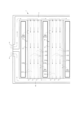
- FIG. 2 is a partially enlarged plan view of the first embodiment of the battery cooling heat exchanger.
- FIG. 3 is an exploded perspective view of the battery cooling heat exchanger of FIG. 2 before the first metal plate and the second metal plate are assembled.
- FIG. 4 is a diagram showing a cross section of a tube component in the battery cooling heat exchanger of FIG. Sectional views, (b) is an enlarged sectional view of a second side clearance portion, and (c) is an enlarged sectional view of a first side clearance portion.
- FIG. 1 is a schematic diagram of the overall configuration of a battery cooling heat exchanger according to the present invention and a heat medium cycle including this battery cooling heat exchanger.
- FIG. 2 is a partially enlarged plan view of the first embodiment of the battery cooling heat exchanger.
- FIG. 3 is an exploded perspective view of the battery cooling heat exchanger of
- FIG. 5 is a perspective view showing a closed portion provided in the middle of the side gap and its vicinity in the battery cooling heat exchanger of FIG. (c) and (d) are perspective views showing the middle of the second side gap from different angles.
- FIG. 6 is a partially enlarged plan view of the second embodiment of the battery cooling heat exchanger. 7 is an exploded perspective view of the battery cooling heat exchanger of FIG. 6 before assembling the first metal plate and the second metal plate.
- FIG. FIG. 8 is a diagram showing a cross section of a tube component in a battery cooling heat exchanger that employs the first modified example.
- 1B is an enlarged cross-sectional view of a second side clearance portion; and (c) is an enlarged cross-sectional view of a first side clearance portion.
- FIG. 9 is an exploded perspective view of the battery cooling heat exchanger of the third modification, before the first metal plate and the second metal plate are assembled.
- FIG. 10 is a schematic cross-sectional view showing a conventional battery cooling heat exchanger for cooling a battery, (a) is an overall cross-sectional view showing a state in which it is in thermal contact with the battery, and (b) is a side view. 4 is an enlarged cross-sectional view showing the vicinity of the gap; FIG.
- FIG. 1 is a schematic diagram of the overall configuration of a battery cooling heat exchanger according to the present invention and a coolant cycle including this battery cooling heat exchanger.
- a large number of batteries A indicated by a dashed line are placed on the battery cooling heat exchanger 1 so as to be thermally coupled.
- a battery cooling heat exchanger 1 includes an inlet 2 for inflowing a cooling medium such as cold water, and an outlet 3 for outflowing the cooling medium.
- the inlet 2 and the outlet 3 are connected via piping 4 to an external heat exchanger 5 such as a chiller for cooling the cooling medium.
- the cooling medium is pumped through the pipe 4 by operating the pump 6 installed in the pipe 4 .
- the cooling medium is pumped from the pump 6, flows into the external heat exchanger 5, is cooled, flows out of the external heat exchanger 5, flows into the inlet 2, and cools the battery in the battery cooling heat exchanger 1.
- It exchanges heat with A, is heated, flows out from the outlet 3, and flows into the pump 6 via the pipe 4. That is, the cooling medium is circulated between the battery cooling heat exchanger 1 and the external heat exchanger 5 by the pump 6 installed in the pipe 4 while transporting heat.
- FIG. 2 is a partially enlarged plan view of the first embodiment of the battery cooling heat exchanger.
- the battery cooling heat exchanger 1 includes an upstream header portion 7 communicating with the inflow port 2 and an upstream header portion 7 communicating with the outflow port 3 and separated from the upstream header portion 7 and extending substantially parallel to the upstream header portion 7. It has a downstream header portion 8 and a plurality of tube forming portions 9 extending so as to communicate between the upstream header portion 7 and the downstream header portion 8 .
- FIG. 3 is an exploded perspective view of the battery cooling heat exchanger of FIG. 2 before the first metal plate 10 and the second metal plate 20 are assembled.
- the upstream header portion 7, the downstream header portion 8, and the tube structure portion 9 are formed by a first metal plate 10 and a second metal plate 20 assembled therewith.
- the first metal plate 10 and the second metal plate 20 are laminated after being press-worked so that each has a predetermined shape, and are joined by a brazing process.
- the material of the first metal plate 10 and the second metal plate 20 it is preferable to use an aluminum alloy or a copper alloy. Brazing can be performed.
- the first metal plate 10 has a plurality of main bulges 11 bulging at predetermined intervals, leaving a brazing allowance, and bulges so that both ends of the adjacent main bulges 11 communicate with each other.
- the second metal plate 20 is formed to have approximately the same size as the first metal plate 10, and has a flat portion 21 formed flat with a projection 22 described later. .
- the main bulging portion 11 of the first metal plate 10 and the portion of the second metal plate 20 where the ridges 22 are formed form the tube forming portion 9 (see FIGS. 1 and 2).
- An upstream header portion 7 and a downstream header portion 8 are formed by the end portion of the bulging portion 11 , the relay bulging portion 12 , and the flat portion 21 of the second metal plate 20 .
- FIG. 4 is a cross-sectional view of the tube-constituting portion 9 of the battery cooling heat exchanger of FIG.
- a portion of the first metal plate 10 that forms the tube-constituting portion 9, that is, the main swelling portion 11 includes a flat swelling surface 11a that swells toward the battery A and one side edge of the swelling surface 11a. and a second side wall surface 11c formed on the other side edge of the bulging surface.
- a portion of the second metal plate 20 that forms the tube-constituting portion 9 bulges so as to be joined to the bulging surface 11a, and has a plurality of ridges 22 ( 22a, 22b, 22c, 22d).
- the tube-constituting portion 9 includes a first side gap portion 30a formed by a first side wall surface 11b, an adjacent ridge 22a, a bulging surface 11a, and a flat portion 21, a second side wall surface 11c, and an adjacent ridge 22a.
- the cooling medium flow section 40 is formed by linear passages 40a, 40b, and 40c formed in parallel. Although the number of passages is shown as three in FIGS. 3 and 4, it is not limited to this. The number of passages formed in one tube-constituting portion 9 may be one or plural, and is set as appropriate.
- Widths P1, P2, and P3 of the heat exchanging regions of the cooling medium flowing portion 40 facing the bulging surface 11a are the widths of the heat exchanging regions of the first side gaps 30a facing the bulging surface 11a. It is formed wider than the width S1 and the width S2 of the second gap portion heat exchange region facing the bulging surface 11a in the second side gap portion 30b.
- the first side gap portion 30a is closed between the upstream side header portion 7 and the downstream side header portion 8 by a first closing portion 50a, which will be described later.
- the portion 50b closes between the upstream header portion 7 and the downstream header portion 8 .
- FIG. 5 is a perspective view of the battery cooling heat exchanger of FIG. 2 showing a closed portion provided in the side gap and its vicinity.
- the first closing portion 50a is formed by a first notch 51a provided in the second metal plate.
- the first notch 51a is a portion protruding from the ridge 22a toward the side wall surface 11b so as to block the first side gap 30a.
- the second closing portion 50b is formed by a second notch 51b provided in the second metal plate.
- the second notch 51b is a portion protruding from the ridge 22d toward the side wall surface 11c so as to close the second side gap 30b.
- the notches protrude so as to abut not only the respective side wall surfaces (11b, 11c) but also the bulging surface 11a, thereby forming a passageway of the cooling medium flow section 40.
- the side gaps (the first side gap 30a and the second side gap 30b) have substantially the same cross-sectional shape.
- the upper surfaces of the notches (first notch 51a, second notch 51b) are brazed to the bulging surface 11a of the first metal plate 10, and the notches (first notch 51a, second notch 51b) are brazed.
- the side surfaces can be brazed to the side wall surfaces 11 b and 11 c of the first metal plate 10 .
- the notches are formed, for example, in a process of pressing the second metal plate 20. As shown in FIG.
- a first closing portion 50a that closes the first side gap portion 30a is provided at a position closer to the upstream header portion 7 than an intermediate position in the extending direction of the tube forming portion 9, and closes the second side gap portion 30b.
- the second closing portion 50 b is provided at a position closer to the downstream header portion 8 than the intermediate position of the tube forming portion 9 .
- the cooling medium that has flowed in from the inlet 2 flows through the upstream header section 7 and branches to the cooling medium flow section 40 of each tube forming section 9 . Since the cooling medium flow part 40 of each tube structure part 9 is formed by a plurality of linear passages arranged in parallel, the cooling medium flowing from the upstream header part 7 into each cooling medium flow part 40 is , move toward the downstream header portion 8 . During this moving process, heat is exchanged between the battery A and the cooling medium via the bulging surface 11a that contacts the battery A, and the battery A is cooled. The cooling medium that has flowed through each cooling medium flow section 40 flows into the downstream header section 8 , is collected here, flows out from the outlet 3 , and is sent to the external heat exchanger 5 .
- the cooling medium also enters the first side gap portion 30a and the second side gap portion 30b.
- the width S1 of the first gap heat exchange area facing the exit surface 11a and the width S2 of the second gap heat exchange area are the same as the width S1 of the heat exchange area of the second gap part heat exchange area facing the bulging surface 11a of each cooling medium flow part 40. Therefore, the side gaps (first side gap 30a, second side gap 30b) that contribute less to heat exchange with the battery A are made smaller and the battery It is possible to secure a large contact area between A and the cooling medium flow portion 40 . Therefore, it is possible to improve the heat exchange efficiency between the battery A and the cooling medium.
- the side gaps (first When the cooling medium flows through the side gap portion 30 a and the second side gap portion 30 b ), the heat exchange efficiency is inferior to that of the cooling medium flowing portion 40 .
- the first side gap portion 30a is closed between the upstream side header portion 7 and the downstream side header portion 8 by the first closing portion 50a, and the second side gap portion 30b is closed by the second closing portion 50b on the upstream side. A space between the header portion 7 and the downstream header portion 8 is blocked.
- the cooling medium does not flow through the respective side gaps (the first side gap 30a and the second side gap 30b), and all of the cooling medium branched to the tube-constituting portion 9 is cooled. It can flow to the medium flow part 40, and the heat exchange efficiency with the battery A can be improved.
- the notches 51a and 51b are provided in the side gaps on both sides (the first side gap 30a and the second side gap 30b).
- the notches 51a and 52b formed in the second metal plate 20 are brought into contact with the bulging surface 11a and the two side wall surfaces 11b and 11c to form the side gap (first side gap 30a , the second side gap 30b) can be easily closed.
- the first side wall surface 11b and the side surface of the ridge 22a facing the first side wall surface 11b and the side surface of the second side wall surface 11c and the ridge 22d facing the second side wall surface 11c are slanted so as to expand outward as the distance from the battery A increases. , the assembly of the first metal plate and the second metal plate should be facilitated.
- the side gaps (the first side gap 30a and the second side gap 30b). It is difficult to form the ridges 22 so as to eliminate the side gap portion 30a and the second side gap portion 30b) in consideration of molding errors and assembly errors. Therefore, even if the overlapping position of the first metal plate 10 and the second metal plate 20 can be adjusted to eliminate the side gap at one side edge of the tube-constituting portion 9, the other side edge has a side gap. A gap will remain. Therefore, when only one of the first side gap portion 30a and the second side gap portion 30b is to be formed, only the closing portion corresponding to that side gap portion should be formed.
- the first closing portion 50a provided in the first side gap portion 30a and the second closing portion 50b provided in the second side gap portion 30b are provided at different distances from the upstream side header portion 7 or the downstream side header portion 8. (The formation position is different in the extending direction of the tube-constituting portion 9), the strength of the tube-constituting portion 9 is not impaired.
- the formation positions of the first closing portion 50a that closes the first side gap portion 30a and the second closing portion 50b that closes the second side gap portion 30b are formed at the same positions in the extending direction of the tube forming portion 9.
- the thinned portions are formed at the same position in the extension direction on both side edges of the tube-constituting portion 9, and there is a concern that the strength may be lowered.
- the first notch 51a forming the first closing portion 50a and the second notch 51b forming the second closing portion 50b are provided at different positions in the extending direction of the tube forming portion 9. Therefore, it is possible to reduce the possibility that the relatively thin portion or the strain-accumulated portion will deviate in the extension direction, resulting in a decrease in strength.
- first side gap portion 30a and second side gap portion 30b two or more closing portions for closing the side gap portions are provided in one side gap portion.
- a closed space in which gas (air) is sealed is formed in the side gap portion by the adjacent closed portions. Since the sealed gas and the cooling medium have different expansion coefficients with respect to temperature, there is a concern that unintended stress may occur in response to temperature changes in the heat exchanger. For this reason, it is preferable that one closing portion be provided in one side gap portion.
- FIG. 6 is a partially enlarged plan view of the second embodiment of the battery cooling heat exchanger.
- 7 is an exploded perspective view of the battery cooling heat exchanger of FIG. 6 before assembling the first metal plate and the second metal plate.
- FIG. One end of the cooling medium passage portion 40 communicates with the upstream header portion 7 , the other end communicates with the downstream header portion 8 , and an intermediate portion extends between the vicinity of the upstream header portion 7 and the vicinity of the downstream header portion 8 . formed by a meandering passageway between
- the first circulation portion 40a' communicates with the upstream header portion 7 and extends to the vicinity of the downstream header portion 8, and the first circulation portion 40a' is connected to the turn-back circulation portion 40d.
- a second circulation portion 40b' extending from the vicinity of the downstream header portion 8 to the vicinity of the upstream header portion 7; and a third flow portion 40c' communicating with the downstream side header portion 8 from the vicinity of , and the entirety is formed in an S shape.
- the cooling medium flowing through the upstream header portion 7 extends through the tube structure portion 9 to the downstream header portion 8. Since it reciprocates one and a half times in the direction, it is possible to reduce the temperature difference between the cells of the battery A installed near the upstream header portion 7 and the cells of the battery A installed near the downstream header portion 8. Become.
- the coolant is not meandered (in the case of the first embodiment in which the cooling medium flows linearly from the upstream header portion 7 to the downstream header portion 8)
- the battery A near the downstream header portion with respect to the upstream header portion near the battery A the cooling capacity of the battery A decreases, and the temperature distribution of the cells of the battery A increases.
- the temperature of the cooling medium flowing through the second flow portion 40b' is lower near the downstream header portion 8 than near the upstream header portion 7, and the temperature near the upstream header portion is lower than that near the upstream header portion.
- the cooling capacity of the battery A in the vicinity of the portion can be enhanced, and the temperature distribution of the battery can be reduced in the extending direction of the tube-constituting portion 9 .
- the passage resistance of the cooling medium passage portion 40 is relatively high with respect to the first side gap portion 30a and the second side gap portion 30b.
- the side gap 30b is easily flowed, the first side gap 30a is closed by the first closing part 50a, and the second side gap 30b is closed by the second closing part 50b. It is possible to block the flowing cooling medium and effectively prevent the deterioration of the heat exchange efficiency.
- FIG. 8 is a cross-sectional view of the tube-constituting portion 9 of the battery cooling heat exchanger of Modification 1, in which the upstream header portion 7 is viewed from the downstream header portion 8 .
- the dimension (H1) by which the bulging surface 11a of the first metal plate 10 bulges is set larger than the distance (H2) between the bulging surface 11a and the second metal plate 20 in the cooling medium flow portion 40.
- the distance between the bulging surface 11a and the second metal plate 20 in the first side gap 30a and the second side gap 30b is the same as the bulging dimension of the bulging surface 11a.
- the distance between the bulging surface 11a and the second metal plate 20 is larger than the distance between the bulging surface 11a and the second metal plate 20. Therefore, the flat portion 21' forming the lower end of the cooling medium flow portion 40 of the tube-constituting portion 9 is located between the side gap portions 30a and 30b. It is located above the flat portion 21 that forms the lower end (the so-called raised bottom prevents the cooling medium passage 40 from becoming deep). Since other configurations are the same as those of the above configuration example, the same reference numerals are given to the same portions, and description thereof will be omitted.
- the height of the main swelling portion 11 (the dimension H1 of swelling of the swelling surface 11a) is set to the height of the cooling medium flow portion 40 (the swelling surface 11a of the cooling medium flow portion 40). and the second metal plate 20, it is possible to secure contact with the battery A by increasing the bulging amount of the bulging surface 11a. That is, it becomes easy to thermally couple the battery cooling heat exchanger to the battery A according to the layout of the battery A mounted on the vehicle.
- the cooling medium flow portion 40 by setting the cooling medium flow portion 40 to a so-called raised bottom, the expansion of the flow passage cross-sectional area of the cooling medium flow portion 40 is suppressed, and the decrease in the flow velocity of the cooling medium is suppressed, thereby heat exchange in the tube structure portion 9. It becomes possible to avoid a decrease in efficiency.
- FIG. 9 is an exploded perspective view of the battery cooling heat exchanger of the third modified example, before the first metal plate 10 and the second metal plate 20 are assembled.
- the upstream header portion 7 and the downstream header portion 8 described in the first and second embodiments are formed by providing the main swelling portion 11 and the relay swelling portion 12 formed on the first metal plate.
- both the relay swelling portion 12 and the recess portion 23 may be formed.
- the three modified examples described above can be used independently for the first embodiment and the second embodiment, respectively, and can also be used after appropriately combining two or three modified examples.
Landscapes
- Engineering & Computer Science (AREA)
- Chemical Kinetics & Catalysis (AREA)
- General Chemical & Material Sciences (AREA)
- Electrochemistry (AREA)
- Manufacturing & Machinery (AREA)
- Chemical & Material Sciences (AREA)
- Physics & Mathematics (AREA)
- General Engineering & Computer Science (AREA)
- Mechanical Engineering (AREA)
- Thermal Sciences (AREA)
- Algebra (AREA)
- General Physics & Mathematics (AREA)
- Mathematical Analysis (AREA)
- Mathematical Optimization (AREA)
- Pure & Applied Mathematics (AREA)
- Secondary Cells (AREA)
Abstract
Description
このため、バッテリAとの熱交換効率が劣るサイド間隙部を備えたバッテリ冷却用熱交換器においては、バッテリの冷却効率を高める工夫が求められるものであった。
前記第1金属プレート10と前記第2金属プレート20により、前記冷却媒体を流入する流入口2と通じる上流側ヘッダ部7と、前記冷却媒体を流出する流出口3に通じると共に前記上流側ヘッダ部7と離間する下流側ヘッダ部8と、前記上流側ヘッダ部7と前記下流側ヘッダ部8とを連通するように延設される複数のチューブ構成部9とが形成され、
前記第1金属プレート10のうち前記チューブ構成部9を形成する部分は、前記バッテリAに向かって膨出された膨出面11aと、当該膨出面11aの一方の側縁に形成された第1側壁面11bと,当該膨出面の他方の側縁に形成された第2側壁面11cとを備え、
前記第2金属プレート20のうち前記チューブ構成部9を形成する部分は、前記膨出面11aに接合されるよう平坦部21,21’から膨出すると共に前記チューブ構成部9の延設方向に沿って延びる複数の突条22を備え、
前記チューブ構成部9は、前記第1側壁面11b、これと隣り合う前記突条22、前記膨出面11a、及び前記平坦部21により形成された第1サイド間隙部30aと、前記第2側壁面11c、これと隣り合う前記突条22、前記膨出面11a、及び前記平坦部21により形成された第2サイド間隙部30bのいずれか一方または両方と、隣り合う前記突条22(22aと22b、22bと22c、22cと22d)、前記膨出面11a、及び隣り合う突条の間の平坦部21,21’とにより形成された冷却媒体通流部40と、第1閉塞部50aと第2閉塞部50bのいずれか一方または両方と、
を有し、
前記冷却媒体通流部40のうち前記膨出面11aに臨んだ通流部熱交換領域の幅P(P1,P2,P3)は、前記第1サイド間隙部30aのうち前記膨出面11aに臨んだ第1間隙部熱交換領域の幅S1、及び前記第2サイド間隙部30bのうち前記膨出面11aに臨んだ第2間隙部熱交換領域の幅S2よりも広く形成され、
前記第1サイド間隙部30aは、前記第1閉塞部50aによって前記上流側ヘッダ部7と前記下流側ヘッダ部8との間で閉塞され、前記第2サイド間隙部30bは、前記第2閉塞部50bによって前記上流側ヘッダ部7と前記下流側ヘッダ部8との間で閉塞されていることを特徴としている。
図1は、本発明に係るバッテリ冷却用熱交換器の全体構成と、このバッテリ冷却用熱交換器を含む冷却媒体サイクルの概略図である。一点鎖線で示される多数のバッテリAは、バッテリ冷却用熱交換器1の上に熱的に結合されるように載置されている。バッテリ冷却用熱交換器1は、冷水等の冷却媒体を流入する流入口2と、冷却媒体を流出する流出口3とを備える。流入口2と流出口3は、配管4を介して、冷却媒体を冷却するチラー等の外部熱交換器5に接続される。冷却媒体は、配管4に設置されたポンプ6が作動することで、配管4内を圧送される。これにより、冷却媒体は、ポンプ6から圧送されて外部熱交換器5に流入し、冷却され、外部熱交換器5から流出して流入口2に流入し、バッテリ冷却用熱交換器1でバッテリAと熱交換し、加熱されて流出口3から流出し、配管4を経由してポンプ6に流入する。すなわち、冷却媒体は、配管4に設置されたポンプ6によってバッテリ冷却用熱交換器1と外部熱交換器5との間を、熱の輸送を伴いつつ循環する。
図2は、バッテリ冷却用熱交換器の第1実施例の一部を拡大して示した平面図である。バッテリ冷却用熱交換器1は、流入口2と通じる上流側ヘッダ部7と、流出口3に通じると共に上流側ヘッダ部7と離間し、該上流側ヘッダ部7と略平行に延設された下流側ヘッダ部8と、上流側ヘッダ部7と下流側ヘッダ部8とを連通するように延設される複数のチューブ構成部9と、を有している。
以上の例においては、チューブ構成部9とバッテリAとの間で高い熱交換効率が得られる構成を提供できるものであるが、チューブ構成部9を流れる冷却媒体は、上流側ヘッダ部7から下流側ヘッダ部8に向けて直線状に流れるだけであるので、上流側ヘッダ部7に近いバッテリAのセルは下流側ヘッダ部8に近いバッテリAのセルよりも相対的によく冷却されることになり、バッテリ全体が均一に冷却されない不都合が懸念される。そこで、第2実施例として図6及び図7に示されるように、冷却媒体通流部40の形状を工夫することでバッテリAを均一に冷却するようにしてもよい。なお、以下の第2実施例の説明では、第1実施例と共通する部分については同じ符号を用いて説明を省略し、第1実施例との相違点を中心に説明する。
図8を参照する。図8は、変形例1のバッテリ冷却用熱交換器についてチューブ構成部9の断面を示した図であり、下流側ヘッダ部8から上流側ヘッダ部7を見ている。第1金属プレート10の膨出面11aが膨出する寸法(H1)は、冷却媒体通流部40における膨出面11aと第2金属プレート20との距離(H2)よりも大きく設定されている。第1サイド間隙部30aと第2サイド間隙部30bにおける膨出面11aと第2金属プレート20との距離は、膨出面11aが膨出する寸法と同じに形成されているが、冷却媒体通流部40における膨出面11aと第2金属プレート20との距離より大きく形成されるので、チューブ構成部9の冷却媒体通流部40の下端を形成する平坦部21’は、サイド間隙部30a,30bの下端を形成する平坦部21よりも上方に位置している(所謂、上げ底にすることで、冷却媒体通路40の深さが深くなることを回避している)。
なお、他の構成は、前記構成例と同様であるので、同一箇所に同一符号を付して説明を省略する。
ここまで、閉塞部50a,50bを第2金属プレート20に形成したノッチ51a,51bによって形成した例を示したが、第1金属プレート10に形成されたノッチによって形成しても、あるいは、第1金属プレート10と第2金属プレート20のそれぞれに形成されたノッチを突き合せて形成してもよい。
図9を参照する。図9は、第3変形例のバッテリ冷却用熱交換器について、第1金属プレート10と第2金属プレート20とを組み付ける前の、分解斜視図である。実施例1及び実施例2で説明した上流側ヘッダ部7と下流側ヘッダ部8は、第1金属プレートに形成されたメイン膨出部11と中継膨出部12を設けることで形成したが、図9に示すように、メイン膨出部11間を連通するように第2金属プレート20に凹部23を形成することで第1金属プレート10に中継膨出部12の形成を無くすようにしてもよい。あるいは、中継膨出部12と凹部23との両方を形成してもよい。
2 流入口
3 流出口
7 上流側ヘッダ部
8 下流側ヘッダ部
9 チューブ構成部
10 第1金属プレート
11 メイン膨出部
11a 膨出面
11b 第1側壁面
11c 第2側壁面
20 第2金属プレート
21,21’ 平坦部
22、22a~22d 突条
30a 第1サイド間隙部
30b 第2サイド間隙部
40 冷却媒体通流部
50a 第1閉塞部
50b 第2閉塞部
51a 第1ノッチ
51b 第2ノッチ
A バッテリ
Claims (7)
- バッテリAと熱的に接触して前記バッテリAを冷却するためのバッテリ冷却用熱交換器1であって、前記バッテリAと熱的に接触可能とする第1金属プレート10と、この第1金属プレート10に対して組み付けられる第2金属プレート20と、を備え、前記第1金金属プレート10と前記第2金属プレート20の間に冷却媒体を通流させるバッテリ冷却用熱交換器1において、
前記第1金属プレート10と前記第2金属プレート20により、前記冷却媒体を流入する流入口2と通じる上流側ヘッダ部7と、前記冷却媒体を流出する流出口3に通じると共に前記上流側ヘッダ部7と離間する下流側ヘッダ部8と、前記上流側ヘッダ部7と前記下流側ヘッダ部8とを連通するように延設される複数のチューブ構成部9とが形成され、
前記第1金属プレート10のうち前記チューブ構成部9を形成する部分は、前記バッテリAに向かって膨出された膨出面11aと、当該膨出面11aの一方の側縁に形成された第1側壁面11bと,当該膨出面11aの他方の側縁に形成された第2側壁面11cとを備え、
前記第2金属プレート20のうち前記チューブ構成部9を形成する部分は、前記膨出面11aに接合されるよう平坦部21,21’から膨出すると共に前記チューブ構成部9の延設方向に沿って延びる複数の突条22a~22dを備え、
前記チューブ構成部9は、前記第1側壁面11b、これと隣り合う前記突条22a、前記膨出面11a、及び前記平坦部21により形成された第1サイド間隙部30aと、前記第2側壁面11c、これと隣り合う前記突条22d、前記膨出面11a、及び前記平坦部21により形成された第2サイド間隙部30bのいずれか一方または両方と、隣り合う前記突条22a~22d、前記膨出面11a、及び隣り合う突条の間の平坦部21,21’とにより形成された冷却媒体通流部40と、第1閉塞部50aと第2閉塞部50bのいずれか一方または両方と、
を有し、
前記冷却媒体通流部40のうち前記膨出面11aに臨んだ通流部熱交換領域の幅Pは、前記第1サイド間隙部30aのうち前記膨出面11aに臨んだ第1間隙部熱交換領域の幅S1及び前記第2サイド間隙部30bのうち前記膨出面11aに臨んだ第2間隙部熱交換領域の幅S2よりも広く形成され、
前記第1サイド間隙部30aは、前記第1閉塞部50aによって前記上流側ヘッダ部7と前記下流側ヘッダ部8との間で閉塞され、前記第2サイド間隙部30bは、前記第2閉塞部50bによって前記上流側ヘッダ部7と前記下流側ヘッダ部8の間で閉塞されていることを特徴とするバッテリ冷却用熱交換器。 - 前記第1閉塞部50aは、前記第1金属プレート10又は前記第2金属プレート20に形成された前記第1サイド間隙部30aに突出する第1ノッチ51aによって形成され、前記第2閉塞部50bは、前記第1金属プレート10又は前記第2金属プレート20に形成された前記第2サイド間隙部30bに突出する第2ノッチ51bによって形成されることを特徴とする請求項1に記載のバッテリ冷却用熱交換器。
- 前記冷却媒体通流部40は、一端が前記上流側ヘッダ部7に連通し、他端が前記下流側ヘッダ部8に連通し、中間部が前記上流側ヘッダ部7の近傍と前記下流側ヘッダ部8の近傍との間を蛇行する通路を形成することを特徴とする請求項1または請求項2に記載のバッテリ冷却用熱交換器。
- 前記第1金属プレート10の前記膨出面11aが膨出する寸法H1は、前記冷却媒体通流部40における前記膨出面11aと前記第2金属プレート20との距離H2よりも大きく設定されていることを特徴とする請求項1乃至3のいずれかに記載のバッテリ冷却用熱交換器。
- 前記チューブ構成部9は、前記第1サイド間隙部30a及びこれを閉塞する前記第1閉塞部50aと、前記第2サイド間隙部30b及びこれを閉塞する前記第2閉塞部50bと、の両方を有することを特徴とする請求項1乃至4のいずれかに記載のバッテリ冷却用熱交換器。
- 第1サイド間隙部30aに設けられる第1閉塞部50aと第2サイド間隙部30bに設けられる第2閉塞部50bは、前記上流側ヘッダ部7又は前記下流側ヘッダ部8からの距離を異ならせて設けられることを特徴とする請求項5に記載のバッテリ冷却用熱交換器。
- 前記チューブ構成部9は、前記第1サイド間隙部30a及びこれを閉塞する前記第1閉塞部50aと、前記第2サイド間隙部30b及びこれを閉塞する前記第2閉塞部50bと、のいずれか一方を有することを特徴とする請求項1乃至4のいずれかに記載のバッテリ冷却用熱交換器。
Priority Applications (3)
| Application Number | Priority Date | Filing Date | Title |
|---|---|---|---|
| CN202280050383.6A CN117678111A (zh) | 2021-10-05 | 2022-09-27 | 电池冷却用热交换器 |
| EP22878368.4A EP4415111A4 (en) | 2021-10-05 | 2022-09-27 | COIL COOLING HEAT EXCHANGER |
| JP2023552812A JPWO2023058498A1 (ja) | 2021-10-05 | 2022-09-27 |
Applications Claiming Priority (2)
| Application Number | Priority Date | Filing Date | Title |
|---|---|---|---|
| JP2021163939 | 2021-10-05 | ||
| JP2021-163939 | 2021-10-05 |
Publications (1)
| Publication Number | Publication Date |
|---|---|
| WO2023058498A1 true WO2023058498A1 (ja) | 2023-04-13 |
Family
ID=85804262
Family Applications (1)
| Application Number | Title | Priority Date | Filing Date |
|---|---|---|---|
| PCT/JP2022/035893 Ceased WO2023058498A1 (ja) | 2021-10-05 | 2022-09-27 | バッテリ冷却用熱交換器 |
Country Status (4)
| Country | Link |
|---|---|
| EP (1) | EP4415111A4 (ja) |
| JP (1) | JPWO2023058498A1 (ja) |
| CN (1) | CN117678111A (ja) |
| WO (1) | WO2023058498A1 (ja) |
Cited By (1)
| Publication number | Priority date | Publication date | Assignee | Title |
|---|---|---|---|---|
| WO2026069797A1 (ja) * | 2024-09-25 | 2026-04-02 | 株式会社三五 | 電池冷却器 |
Families Citing this family (1)
| Publication number | Priority date | Publication date | Assignee | Title |
|---|---|---|---|---|
| EP4648180A1 (en) * | 2024-05-09 | 2025-11-12 | Aisin Corporation | Heat exchanger |
Citations (4)
| Publication number | Priority date | Publication date | Assignee | Title |
|---|---|---|---|---|
| JP2012043655A (ja) * | 2010-08-19 | 2012-03-01 | Denso Corp | 電池パック |
| JP2019216004A (ja) * | 2018-06-12 | 2019-12-19 | トヨタ自動車株式会社 | 蓄電装置 |
| JP2020009694A (ja) * | 2018-07-11 | 2020-01-16 | パナソニックIpマネジメント株式会社 | 冷却装置、電池温度調整システム及び車両 |
| WO2020213673A1 (ja) | 2019-04-18 | 2020-10-22 | 株式会社ヴァレオジャパン | 車両用バッテリを冷却するための熱交換器 |
Family Cites Families (2)
| Publication number | Priority date | Publication date | Assignee | Title |
|---|---|---|---|---|
| JP7370128B2 (ja) * | 2019-05-24 | 2023-10-27 | 株式会社ヴァレオジャパン | バッテリー冷却システム |
| JP7314655B2 (ja) * | 2019-06-28 | 2023-07-26 | 株式会社デンソー | 熱交換器 |
-
2022
- 2022-09-27 EP EP22878368.4A patent/EP4415111A4/en active Pending
- 2022-09-27 JP JP2023552812A patent/JPWO2023058498A1/ja active Pending
- 2022-09-27 WO PCT/JP2022/035893 patent/WO2023058498A1/ja not_active Ceased
- 2022-09-27 CN CN202280050383.6A patent/CN117678111A/zh active Pending
Patent Citations (4)
| Publication number | Priority date | Publication date | Assignee | Title |
|---|---|---|---|---|
| JP2012043655A (ja) * | 2010-08-19 | 2012-03-01 | Denso Corp | 電池パック |
| JP2019216004A (ja) * | 2018-06-12 | 2019-12-19 | トヨタ自動車株式会社 | 蓄電装置 |
| JP2020009694A (ja) * | 2018-07-11 | 2020-01-16 | パナソニックIpマネジメント株式会社 | 冷却装置、電池温度調整システム及び車両 |
| WO2020213673A1 (ja) | 2019-04-18 | 2020-10-22 | 株式会社ヴァレオジャパン | 車両用バッテリを冷却するための熱交換器 |
Non-Patent Citations (1)
| Title |
|---|
| See also references of EP4415111A4 |
Cited By (1)
| Publication number | Priority date | Publication date | Assignee | Title |
|---|---|---|---|---|
| WO2026069797A1 (ja) * | 2024-09-25 | 2026-04-02 | 株式会社三五 | 電池冷却器 |
Also Published As
| Publication number | Publication date |
|---|---|
| CN117678111A (zh) | 2024-03-08 |
| JPWO2023058498A1 (ja) | 2023-04-13 |
| EP4415111A4 (en) | 2025-08-27 |
| EP4415111A1 (en) | 2024-08-14 |
Similar Documents
| Publication | Publication Date | Title |
|---|---|---|
| CN102138054B (zh) | 包括热交换器束和壳体的热交换器 | |
| US8925624B2 (en) | Exhaust heat exchanger | |
| CN101165332A (zh) | 热交换器 | |
| WO2023058498A1 (ja) | バッテリ冷却用熱交換器 | |
| JP4941398B2 (ja) | 積層型冷却器 | |
| KR20180136257A (ko) | 플레이트 열교환기 | |
| JP2004218983A (ja) | 熱交換器 | |
| JP2008166423A (ja) | 冷却管およびその製造方法 | |
| CN111129645B (zh) | 一种换热装置 | |
| JPH079865A (ja) | 電気自動車用放熱器 | |
| KR102488058B1 (ko) | 차량의 전기소자 냉각용 열교환기 | |
| JP5393606B2 (ja) | 熱交換器 | |
| JP2022549576A (ja) | 熱交換器 | |
| JP7765995B2 (ja) | 熱交換器 | |
| KR100389699B1 (ko) | 수냉식 열교환기 | |
| JP7210646B2 (ja) | ヒートシンク及び熱交換器 | |
| JP7594395B2 (ja) | 熱交換器 | |
| CN111512112A (zh) | 板翅片层叠型热交换器和使用它的制冷系统 | |
| JP2019066054A (ja) | 熱交換器 | |
| JP2023101130A (ja) | 熱交換器 | |
| JP2010117101A (ja) | プレート式熱交換器 | |
| JP2006292307A (ja) | 多板式熱交換器 | |
| CN112378285A (zh) | 芯片、芯体及换热器 | |
| JP6699588B2 (ja) | 熱交換器 | |
| US20240314978A1 (en) | Cooling device |
Legal Events
| Date | Code | Title | Description |
|---|---|---|---|
| 121 | Ep: the epo has been informed by wipo that ep was designated in this application |
Ref document number: 22878368 Country of ref document: EP Kind code of ref document: A1 |
|
| WWE | Wipo information: entry into national phase |
Ref document number: 2023552812 Country of ref document: JP |
|
| WWE | Wipo information: entry into national phase |
Ref document number: 202280050383.6 Country of ref document: CN |
|
| WWE | Wipo information: entry into national phase |
Ref document number: 2022878368 Country of ref document: EP |
|
| NENP | Non-entry into the national phase |
Ref country code: DE |
|
| ENP | Entry into the national phase |
Ref document number: 2022878368 Country of ref document: EP Effective date: 20240506 |