WO2023063428A1 - 多芯ケーブルの加工装置 - Google Patents
多芯ケーブルの加工装置 Download PDFInfo
- Publication number
- WO2023063428A1 WO2023063428A1 PCT/JP2022/038481 JP2022038481W WO2023063428A1 WO 2023063428 A1 WO2023063428 A1 WO 2023063428A1 JP 2022038481 W JP2022038481 W JP 2022038481W WO 2023063428 A1 WO2023063428 A1 WO 2023063428A1
- Authority
- WO
- WIPO (PCT)
- Prior art keywords
- core
- multicore cable
- multicore
- cable
- sheath
- Prior art date
- Legal status (The legal status is an assumption and is not a legal conclusion. Google has not performed a legal analysis and makes no representation as to the accuracy of the status listed.)
- Ceased
Links
Images





Classifications
-
- H—ELECTRICITY
- H01—ELECTRIC ELEMENTS
- H01R—ELECTRICALLY-CONDUCTIVE CONNECTIONS; STRUCTURAL ASSOCIATIONS OF A PLURALITY OF MUTUALLY-INSULATED ELECTRICAL CONNECTING ELEMENTS; COUPLING DEVICES; CURRENT COLLECTORS
- H01R43/00—Apparatus or processes specially adapted for manufacturing, assembling, maintaining, or repairing of line connectors or current collectors or for joining electric conductors
- H01R43/28—Apparatus or processes specially adapted for manufacturing, assembling, maintaining, or repairing of line connectors or current collectors or for joining electric conductors for wire processing before connecting to contact members, not provided for in groups H01R43/02 - H01R43/26
-
- B—PERFORMING OPERATIONS; TRANSPORTING
- B21—MECHANICAL METAL-WORKING WITHOUT ESSENTIALLY REMOVING MATERIAL; PUNCHING METAL
- B21F—WORKING OR PROCESSING OF METAL WIRE
- B21F1/00—Bending wire other than coiling; Straightening wire
- B21F1/02—Straightening
-
- B—PERFORMING OPERATIONS; TRANSPORTING
- B21—MECHANICAL METAL-WORKING WITHOUT ESSENTIALLY REMOVING MATERIAL; PUNCHING METAL
- B21F—WORKING OR PROCESSING OF METAL WIRE
- B21F7/00—Twisting wire; Twisting wire together
-
- B—PERFORMING OPERATIONS; TRANSPORTING
- B21—MECHANICAL METAL-WORKING WITHOUT ESSENTIALLY REMOVING MATERIAL; PUNCHING METAL
- B21F—WORKING OR PROCESSING OF METAL WIRE
- B21F9/00—Straining wire
- B21F9/002—Straining wire to maintain tension in the wire, e.g. to pull the wire taut
-
- H—ELECTRICITY
- H01—ELECTRIC ELEMENTS
- H01B—CABLES; CONDUCTORS; INSULATORS; SELECTION OF MATERIALS FOR THEIR CONDUCTIVE, INSULATING OR DIELECTRIC PROPERTIES
- H01B13/00—Apparatus or processes specially adapted for manufacturing conductors or cables
- H01B13/06—Insulating conductors or cables
- H01B13/08—Insulating conductors or cables by winding
- H01B13/0891—After-treatment
-
- H—ELECTRICITY
- H02—GENERATION; CONVERSION OR DISTRIBUTION OF ELECTRIC POWER
- H02G—INSTALLATION OF ELECTRIC CABLES OR LINES, OR OF COMBINED OPTICAL AND ELECTRIC CABLES OR LINES
- H02G1/00—Methods or apparatus specially adapted for installing, maintaining, repairing or dismantling electric cables or lines
- H02G1/12—Methods or apparatus specially adapted for installing, maintaining, repairing or dismantling electric cables or lines for removing insulation or armouring from cables, e.g. from the end thereof
- H02G1/1202—Methods or apparatus specially adapted for installing, maintaining, repairing or dismantling electric cables or lines for removing insulation or armouring from cables, e.g. from the end thereof by cutting and withdrawing insulation
- H02G1/1248—Machines
- H02G1/1251—Machines the cutting element not rotating about the wire or cable
- H02G1/1253—Machines the cutting element not rotating about the wire or cable making a transverse cut
- H02G1/1256—Machines the cutting element not rotating about the wire or cable making a transverse cut using wire or cable-clamping means
-
- Y—GENERAL TAGGING OF NEW TECHNOLOGICAL DEVELOPMENTS; GENERAL TAGGING OF CROSS-SECTIONAL TECHNOLOGIES SPANNING OVER SEVERAL SECTIONS OF THE IPC; TECHNICAL SUBJECTS COVERED BY FORMER USPC CROSS-REFERENCE ART COLLECTIONS [XRACs] AND DIGESTS
- Y02—TECHNOLOGIES OR APPLICATIONS FOR MITIGATION OR ADAPTATION AGAINST CLIMATE CHANGE
- Y02W—CLIMATE CHANGE MITIGATION TECHNOLOGIES RELATED TO WASTEWATER TREATMENT OR WASTE MANAGEMENT
- Y02W30/00—Technologies for solid waste management
- Y02W30/50—Reuse, recycling or recovery technologies
- Y02W30/82—Recycling of waste of electrical or electronic equipment [WEEE]
Definitions
- the present invention relates to a processing device for multicore cables.
- Patent Document 1 After the sheath is removed to expose the covered wire (core wire) and the drain wire, the drain wire is bent 90 degrees to be separated from the core wire, and the drain wire is inserted into a heat-shrinkable tube. A method of insulating a drain line is disclosed. In the method disclosed in Patent Literature 1, the drain wire is then insulated by heat-shrinking the heat-shrinkable tube.
- a multi-core cable processing apparatus is an apparatus for processing a multi-core cable having a sheath and a plurality of core wires inserted through the sheath, wherein a slit is formed in the sheath along the circumferential direction. and a pulling device for exposing the plurality of core wires by moving at least one of the sheath on the tip side of the multicore cable and the sheath on the base side of the cut in the longitudinal direction of the multicore cable. a detecting device for detecting the position of a specific core wire among the plurality of core wires in the circumferential direction of the multicore cable; and rotating the multicore cable based on the detected position of the specific core wire in the circumferential direction. and a rotating device for moving the specific core wire to a predetermined position in the circumferential direction.
- the multicore cable is rotated based on the circumferential position of the specific core wire detected by the detection device, and the position of the specific core wire is changed from the predetermined circumferential position. can do. This makes it possible to identify the positions of the core wires of the multicore cable.
- the plurality of core wires are composed of a drain wire and a plurality of core wires, and the specific core wire is the drain wire.
- the multicore cable processing device urges at least one of the drain wire and the plurality of core wires based on the detected circumferential position of the drain wire, thereby separating the drain wire and the plurality of core wires.
- the processing of the multicore shielded cable up to the insulation treatment of the drain wire can be automatically performed.
- the apparatus for processing a multicore cable further includes a straightening device for straightening the separated drain wires by twisting them in the circumferential direction and applying a tensile tension before the insulation treatment. ing.
- the drain wire can be easily insulated by correcting the drain wire.
- the insulation processing apparatus includes an insertion apparatus for inserting the separated drain wire into a heat-shrinkable tube, and a and a heating device for heating the heat-shrinkable tube.
- insulation processing is performed by inserting the drain wire into the heat-shrinkable tube and heat-shrinking the heat-shrinkable tube. Therefore, compared with other methods, for example, the method of winding an insulating tape around the drain wire, it is easier to perform the insulating treatment by an automatic machine.
- the pulling device rotates the sheath on the distal end side and While rotating at least one of the sheaths on the root side, the sheath on the tip side is pulled out to untwist the plurality of core wires.
- the detection device can easily detect the position of a specific core wire.
- the pull-out device exposes a part of the plurality of core wires, and attaches the other part of the plurality of core wires to the distal end side.
- the semi-stripping of pulling out the sheath on the distal end side so that the sheath remains is performed prior to the detection of the specific core wire by the detection device.
- the extracting device is configured to perform all stripping, in which the sheath on the distal end side is detached from the plurality of core wires, after detection of the specific core wire by the detection device.
- the detection device when detecting the position of a specific core wire by the detection device, it is possible to prevent the core wires from becoming loose and making detection difficult.
- the multi-core cable processing device further includes an alignment device for aligning the plurality of core wires at predetermined intervals.
- the alignment device comprises an alignment member and a moving device.
- the alignment member has a plurality of comb teeth, and a plurality of gaps corresponding to the plurality of core wires are provided between the comb teeth.
- the moving device moves at least one of the alignment member and the multicore cable, and inserts the plurality of core wires into the plurality of gaps of the alignment member.
- the plurality of gaps are formed so as to separate from each other toward the front in the moving direction when the plurality of core wires are inserted, and are arranged at the predetermined intervals at the front end in the moving direction.
- a plurality of core wires are aligned at predetermined intervals, and their respective positions are specified. As a result, it becomes easier to process the plurality of core wires in the post-process.
- the apparatus for processing a multicore cable is configured and loaded with a plurality of gripping members each capable of gripping one of the core wires and a tip portion of the core wire. and a loading device for individually moving the plurality of gripping members and individually loading the core wires gripped by the gripping members into the stripping device.
- the core wires of multi-core cables one by one.
- the plurality of core wires are loaded into the stripping device one by one by the loading device. Therefore, the quality of the core wire strip can be ensured.
- the apparatus for processing a multicore cable further includes a crimping device configured to be loaded with the tip of the core wire and crimping a terminal to the tip of the loaded core wire. ing.
- the loading device is configured to individually move the plurality of gripping members, and individually load the core wires, which are gripped by the gripping members and whose distal ends have been stripped, into the crimping device.
- the plurality of core wires includes a plurality of core wires.
- the multi-core cable processing apparatus further includes a rubber plug mounting device configured to load the tip of the core wire and mounting a waterproof rubber plug to the loaded core wire.
- the loading device individually moves the plurality of gripping members to individually move the core wires gripped by the gripping members to the rubber plug mounting device before the coating of the tip portion of the core wire is stripped. configured to load.
- a multicore cable processing apparatus includes a processing station provided with at least one of the cutting device, the pulling device, the detecting device, and the rotating device; another processing station arranged side by side with the station in a predetermined direction and provided with at least one other of the cutting device, the pulling device, the detecting device, and the rotating device; It further comprises a first conveying device that conveys the multicore cable to the pulling device, the detecting device, and the rotating device.
- the first conveying device includes a gripping device that grips the multicore cable bent so that one end and the other end are aligned in the predetermined direction, a gripping device moving device that moves the gripping device in the predetermined direction, It has The device provided at the other processing station processes the other end of the multicore cable while the device provided at the processing station is processing the one end.
- one end and the other end of the multicore cable can be processed at the same time. Therefore, the cycle time for processing the multicore cable can be shortened.
- a multicore cable processing apparatus includes a first conveying device that conveys the multicore cable to the cutting device, the pulling device, the detecting device, and the rotating device; a stripping device configured to be loaded with a tip portion of a core wire and stripping the coating from the tip portion of the loaded core wire; It further comprises a crimping device that crimps a terminal onto the tip of the stripped core wire, and a second conveying device that conveys the multicore cable to the stripping device and the crimping device.
- the second conveying device includes a carrier having a plurality of gripping members each capable of gripping one core wire, and a carrier moving device that moves the carrier.
- the carrier moving device has a take-up position where the multi-core cable is taken, a first facing position facing the stripping device, a second facing position facing the crimping device, and the multi-core cable after the terminals are crimped. Moving the carrier to and from a release position releasing the core cable.
- the multi-core cable can be conveyed without re-grasping the core wire while stripping the core wire and crimping the terminal. Therefore, there is no fear that the position of the core wire will change due to re-grasping, and it will be stable. Thereby, stripping of the core wire and crimping of the terminal can be performed with high quality.
- the second conveying device includes a plurality of carriers.
- the carrier moving device cyclically moves the plurality of carriers.
- the carrier can be returned from the release position to the take-up position, so the multicore cable can be continuously transported. Moreover, since a plurality of carriers circulate, productivity can be improved.
- the circulatory movement of the carrier includes lateral movement between the take-up position, the first opposing position, and the second opposing position, and the take-up position.
- a cyclical movement including vertical movement between a position, the first opposed position, and a position below the second opposed position.
- the plurality of gripping members of the carrier grip the plurality of core wires when the carrier moves from a position below the take-up position to the take-up position.
- the core wires can be gripped by utilizing the vertical movement during the circulating movement of the carrier, so the process time can be shortened.
- the multicore cable processing apparatus includes a plurality of processing stations provided with one or more of the cutting device, the pulling device, the detecting device, and the rotating device. ing.
- the first conveying device includes a plurality of stationary gripping devices provided to face the plurality of processing stations and gripping the multicore cable, and a plurality of fixed gripping devices configured to grip the multicore cable, respectively. and one or more moving grippers that reciprocate between two adjacent fixed grippers among the fixed grippers.
- the cutting device, the pulling device, the detecting device, and the rotating device which do not require advanced positioning for transporting the multicore shielded cable, use the first conveying device as the multicore cable.
- carry cables Since the first conveying device re-grips the multi-core cable between the moving gripping device and the fixed gripping device, it is difficult to achieve high positional accuracy for each core wire, but the structure is simple.
- a second transport device that does not change grips of the multicore cable transports the multicore cable. Therefore, according to the multicore cable processing apparatus, the processing quality of the multicore cable can be improved while simplifying the processing apparatus as a whole.
- the multicore cable processing apparatus further includes a delivery device that receives the multicore cable from the first transport device and delivers the multicore cable to the second transport device. .
- the multicore cable processing apparatus since the multicore cable is not directly transferred from the first transporting device to the second transporting device, the waiting time of the first transporting device and the second transporting device can be reduced. can. Therefore, it is possible to smoothly transfer the multicore cable from the first conveying device to the second conveying device.
- the plurality of processing stations are arranged side by side in the conveying direction of the multicore cable by the moving gripping device.
- the multicore cable processing apparatus further includes a bending device arranged upstream in the conveying direction from the plurality of processing stations and bending the multicore cable into a substantially U shape so that both ends are aligned in the conveying direction.
- Each of the plurality of fixed gripping devices is configured to grip one end of the multicore cable bent by the bending device.
- the device provided in each of the processing stations is capable of processing the downstream end of the bent multicore cable while the device provided in the processing station adjacent to the upstream side is processing the upstream end of the bent multicore cable. to process.
- one end and the other end of the multicore cable can be processed at the same time. Therefore, the cycle time for processing the multicore cable can be shortened.
- the plurality of gripping members of the carrier are arranged such that the plurality of core wires exposed at the end of the bent multicore cable on the upstream side. and an upstream group that is arranged downstream of the upstream group in the conveying direction and that holds the plurality of core wires exposed at the downstream end of the bent multicore cable. contains groups and
- both ends of the multicore cable bent into a substantially U shape can be gripped even by the second conveying device.
- the plurality of gripping members are configured such that the distance between both ends of the multicore cable is narrower than the distance between the ends of the multicore cable gripped by the plurality of fixed gripping devices.
- the multi-core cable is gripped.
- the processing station where the first conveying device conveys the multicore cable has a degree of freedom in arranging the devices, and the second conveying device narrows the distance between both ends of the multicore cable.
- the length of the processing apparatus in the conveying direction can be shortened.
- the multicore cable processing apparatus further includes a delivery device that receives the multicore cable from the first transport device and delivers the multicore cable to the second transport device.
- the transfer device includes a pair of gripping members that grip both ends of the multicore cable, and a driving device.
- the driving device moves the pair of gripping members toward or away from each other so that the distance between the pair of gripping members corresponds to the distance between both ends of the multicore cable when gripped by the first conveying device. or correspond to the distance between both ends of the multicore cable when it is gripped by the second transport device.
- the distance between both ends of the multicore cable is narrowed by the delivery device that delivers the multicore cable from the first transport device to the second transport device. Therefore, the device for narrowing the space between both ends of the multicore cable and the transfer device can be shared.
- the multicore cable processing apparatus of the present invention it is possible to specify the positions of the multiple core wires of the multicore cable.
- FIG. 1 is a schematic cross-sectional view of a multicore shielded cable;
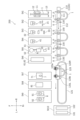
- FIG. 1 is a schematic plan view of a processing apparatus for a multicore shielded cable according to one embodiment;
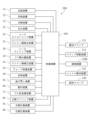
- FIG. 1 is a block diagram of a processing device for a multicore shielded cable;
- FIG. 4 is a schematic side view of a second station;
- FIG. 11 is a schematic plan view of a third station;
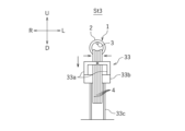
- FIG. 10 is a schematic front view of the third station, showing a state in which the core wire is separated;
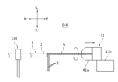
- FIG. 11 is a schematic side view of a fourth station;
- FIG. 11 is a schematic side view of a fifth station;
- FIG. 11 is a schematic plan view of a sixth station;
- FIG. 11 is a schematic front view of the sixth station, showing the state in which the drain wire and the core wire are aligned;
- FIG. 11 is a schematic plan view of a seventh station;
- FIG. 11 is a schematic plan view of an eighth station;
- FIG. 11 is a schematic plan view of a ninth station;
- FIG. 3 is a rear view of a conveying device for a multicore shielded cable;
- FIG. 11 is a rear view of a conveying device for multicore shielded cables according to another embodiment;
- FIG. 1 is a schematic cross-sectional view of a multicore shielded cable 1 according to one example.
- the multicore shielded cable 1 has a sheath 2 , a drain wire 3 and a plurality of core wires 4 inserted through the sheath 2 , and a shield 5 .
- a multicore shielded cable 1 is an electric wire in which a drain wire 3 , a plurality of core wires 4 and a shield 5 are covered with a sheath 2 .
- a plurality of core lines 4 are used, for example, as signal lines for transmitting electrical signals.
- Each of the plurality of core wires 4 has a core wire 4a and an insulator covering 4b covering the core wire 4a.
- the shield 5 is a conductor that shields the core wire 4 from external noise.
- a shield 5 covers the outside of the plurality of core wires 4 .
- Drain wire 3 is electrically connected to shield 5 .
- the drain line 3 is grounded, thereby grounding the shield 5 .
- the drain wire 3 is composed of a plurality of thin conductor strands and is not covered with an insulator.
- the drain wire 3 and a plurality of core wires 4 are twisted together inside the shield 5 .
- the shield 5 is covered by an insulating sheath 2 .
- the number of core wires 4 is not particularly limited.
- the drain wire 3 and the plurality of core wires 4 are not particularly distinguished, they may be collectively referred to as core wires.
- FIG. 2 is a schematic plan view of a processing device (hereinafter simply referred to as a processing device) 200 for the multicore shielded cable 1 according to one embodiment.
- the processing device 200 is a device that insulates the drain wire 3 , crimps the terminals 8 to the ends thereof, and crimps the terminals 8 to the ends of a plurality of core wires 4 .
- the insulating treatment for the drain wire 3 is a treatment for covering the drain wire 3 with a heat-shrinkable tube 6 and heat-shrinking the heat-shrinkable tube 6 .
- the drain wire 3 and the plurality of core wires 4 are also fitted with waterproof rubber plugs 7 , but depending on the specifications of the multicore shielded cable 1 , the fitting of the rubber plugs 7 may be omitted.
- the processing apparatus 200 includes ten stations, a first station St1 to a tenth station St10.
- the multicore shielded cable 1 is conveyed between stations from the first station St1 toward the tenth station St10.
- the first station St1 to the ninth station St9 are arranged side by side in the conveying direction of the multi-core shielded cable 1 (here, the horizontal direction in FIG. 2).
- a process of measuring the length of the multicore shielded cable 1 and cutting it to a predetermined length is performed.
- the sheath 2 is cut and the sheath 2 on the distal end side is pulled out.
- the sheath 2 is not pulled out until the sheath 2 is separated from the multicore shielded cable 1, and is kept inserted into the multicore shielded cable 1. - ⁇ Further, when the sheath 2 is pulled out, the sheath 2 is rotated in the circumferential direction, and the twisted core wires of the multicore shielded cable 1 are untwisted.
- the process performed at the second station St2 is also referred to as "sheath 2 semi-stripping".
- the drain wire 3 exposed by semi-stripping the sheath 2 is detected by a camera 31a (see FIG. 5), and the drain wire 3 is positioned at a predetermined position in the circumferential direction of the multicore shielded cable 1. Rotate the multi-core shielded cable 1 as shown. Further, the sheath 2 is completely pulled out from the multicore shielded cable 1. Hereinafter, the process of completely pulling out the sheath 2 from the multicore shielded cable 1 is also referred to as "all stripping of the sheath 2".
- the drain wire 3 and the plurality of core wires 4 are separated by bending only the plurality of core wires 4 while avoiding the drain wire 3 .
- the straightening process of the drain wire 3 is performed by twisting the drain wire 3 and stretching it straight.
- the drain wire 3 is covered with the heat-shrinkable tube 6, and insulation processing is performed by heat-shrinking the heat-shrinkable tube 6.
- FIG. at the sixth station St6, the plurality of core wires 4 are bent back and aligned with the insulated drain wires 3 .
- each process does not have to be performed according to the division of the stations described above. Which process is performed at which station may be appropriately set, and is not particularly limited. Also, the order of the steps may be changed as appropriate. Furthermore, the processing apparatus 200 does not have to be installed at one place, and may be installed separately at a plurality of places. As will be described later, devices for conveying the multicore shielded cable 1 are different between the second station St2 to the sixth station St6 and the seventh station St7 and subsequent stations. Therefore, for example, the processing apparatus 200 may be divided into an apparatus including the first station St1 to the sixth station St6 and an apparatus including the seventh station St7 to the tenth station St10.
- the first station St1 to the tenth station St10 are equipped with devices for performing processing at each station.
- the first station St1 includes a feeding device 11 for conveying the multi-core shielded cable 1, a length measuring device 12 for measuring the length of the multi-core shielded cable 1, and a cutting device for cutting the multi-core shielded cable 1 to a predetermined length.
- a cutting device 13 is provided.
- a conveying device 110 is provided downstream of the first station St1 for conveying the cut multicore shielded cable 1 to each device of the second station St2 to the sixth station St6.
- the conveying device 110 includes a cutting device 21, a sheath semi-stripping device 22, a drain wire detecting device 31, a sheath stripping device 32, a core wire separating device 33, a drain wire correcting device 41, and an insulation processing device 51, all of which will be described later. , a bend-back device 61 and an alignment device 62 .
- the conveying device 110 bends the multicore shielded cable 1 into a U shape before conveying the multicore shielded cable 1 to the second station St2.
- the function of the conveying device 110 that bends the multicore shielded cable 1 into a U shape is also called a bending device 110A.
- the multicore shielded cable 1 is bent so that both ends are aligned in the direction in which the first station St1 to the ninth station St9 are arranged (horizontal direction in FIG. 2).
- both ends of the multicore shielded cable 1 face toward the stations St1 to St9 (in FIG. 2, the upward direction on the paper surface).
- the conveying device 110 includes a pair of conveying clamps 111 for gripping both ends of the multicore shielded cable 1 bent in a U shape, and the conveying clamps 111 arranged in the direction in which the first station St1 to the ninth station St9 are arranged (left and right in FIG. 2). direction).
- the second station St2 to the sixth station St6 are arranged along the moving path of the transfer clamp 111 by the clamp moving device 112 .
- the processing device 200 is a device that processes both ends of the multicore shielded cable 1 .
- a device provided at one station for example, the second station St2
- a device provided at another processing station for example, the third station St3
- Process the other end As a result, the cycle time for processing the multicore shielded cable 1 is shortened.
- a plurality of pairs of transfer clamps 111 are provided so that the multicore shielded cable 1 can be processed continuously.
- fixing clamps 130 that grip the multicore shielded cable 1 and rotate it in the circumferential direction.
- Each fixing clamp 130 also consists of a pair and grips both ends of the multi-core shielded cable 1 bent in a U shape.
- the fixed clamp 130 of each station receives and grips the multicore shielded cable 1 from the transfer clamp 111 of the transfer device 110 at the entrance of the station. After finishing the processing at each station, the fixed clamp 130 of each station delivers the multicore shielded cable 1 to the transfer clamp 111 .
- the function of the fixed clamp 130 of each station may be performed by the transfer clamp 111 to which a configuration for rotating the multicore shielded cable 1 is added.
- the second station St2 is provided with a cutting device 21 that cuts the sheath 2 and a sheath semi-stripping device 22 that semi-strips the sheath 2 .
- the third station St3 includes a drain wire detection device 31 for detecting the circumferential position of the drain wire 3, a sheath stripping device 32 for stripping the entire sheath 2, a core wire separating device 33 for separating the core wire 4, is provided. Circumferential alignment of the drain wire 3 is performed by the sheath strip device 32 and the fixing clamp 130 based on detection by the drain wire detection device 31 .
- the sheath semi-stripping device 22 and the sheath stripping device 32 may be one device provided at the same station.
- the withdrawal device for withdrawing the sheath 2 may be divided into a plurality as in the present embodiment, or may be integrated into one.
- the semi-stripping of the sheath 2 accompanies the rotation of the multicore shielded cable 1 in the circumferential direction.
- the retraction device is divided into a sheath semi-stripping device 22 , a sheath stripping device 32 and two fixed clamps 130 .
- the apparatus for performing one process may be divided into a plurality of apparatuses, or the apparatus for performing a plurality of processes may be integrated into one.
- a drain wire straightening device 41 for straightening the drain wire 3 is provided at the fourth station St4.
- the drain wire straightening device 41, the sheath semi-stripping device 22, and the sheath stripping device 32 may be one device provided at the same station.
- the above device may be divided into a plurality of devices as in this embodiment, or may be integrated into one device.
- An insulation processing device 51 is provided at the fifth station St5.
- the insulation processing device 51 includes a tube reel 52 around which a reel of the heat-shrinkable tube 6 is wound, a tube mounting device 53 that cuts the heat-shrinkable tube 6 to a predetermined length and inserts the drain wire 3 into the heat-shrinkable tube 6, and a heating device 54 for heat-shrinking the heat-shrinkable tube 6 .
- the sixth station St6 includes a bend-back device 61 for realigning the drain wire 3 and the plurality of core wires 4 separated by the core wire separating device 33, and an alignment device 62 for aligning the drain wire 3 and the plurality of core wires 4. and is provided.
- the bending-back device 61 and the alignment device 62 share a part of the configuration and are integrated.
- the bendback device 61 and the alignment device 62 may be configured separately.
- the multicore shielded cable 1 is rotated in the circumferential direction so that the drain wire 3 and the plurality of core wires 4 are aligned along the horizontal plane. This rotation process is performed by the fixed clamp 130 .
- a device 121 is provided.
- the multicore shielded cable 1 is transferred from the transfer device 110 to the shuttle 120 between the sixth station St6 and the seventh station St7.
- the seventh station St7 to tenth station St10 are arranged along the transport path of the shuttle 120 by the shuttle transport device 121 .
- there are a plurality of shuttles 120 (not shown), which circulate along a looped movement path.
- the shuttle 120 includes a plurality of individual clamps 120a that individually grip the drain wires 3 and a plurality of core wires 4, and a loading device 120b that individually approaches the plurality of individual clamps 120a to the crimping devices 91, 92, etc. there is
- a rubber plug mounting device 71 is provided at the seventh station St7.
- a core wire stripping device 81 is provided at the eighth station St8.
- a right crimping device 91 and a left crimping device 92 are provided at the ninth station St9.
- a right crimping device 91 and a left crimping device 92 are provided at the ninth station St9 because different terminals 8 may be crimped on both ends of the multicore shielded cable 1 bent into a U shape.
- the tenth station St10 is provided with a discharge tray 101 for non-defective products and a discharge tray 102 for defective products.
- the shuttle 120 separates the non-defective multi-core shielded cable 1 on the non-defective product discharge tray 101 and drops the non-defective multi-core shielded cable 1 onto the non-defective product discharge tray 101 .
- the shuttle 120 releases the defective multicore shielded cable 1 on the defective discharge tray 102 and drops the defective multicore shielded cable 1 onto the defective discharge tray 102 . Determination as to whether the product is non-defective or defective is made here at the seventh station St7 to the ninth station St9, respectively.
- the multicore shielded cable 1 determined to be defective is discharged to the discharge tray 102 for defective products without proceeding to the next process.
- FIG. 3 is a block diagram of the processing device 200.
- the processing device 200 includes a control device 150. As shown in FIG. The operation of each part of the processing device 200 is controlled by the control device 150 .
- the control device 150 controls the feeding device 11, the length measuring device 12, the cutting device 13, the cutting device 21, the sheath semi-stripping device 22, the drain wire detecting device 31, the sheath stripping device 32, the core wire A separation device 33, a drain wire straightening device 41, a tube mounting device 53, a heating device 54, a bend-back device 61, an alignment device 62, a rubber plug mounting device 71, a core wire stripping device 81, and a right crimping device.
- control device 150 may include, for example, a central processing unit (hereinafter referred to as a CPU), a ROM in which programs executed by the CPU are stored, and a RAM. Each part of the control device 150 may be configured by software or may be configured by hardware. Also, each unit may be a processor or a circuit. Control device 150 may be, for example, a programmable controller, a computer, or the like.
- a CPU central processing unit
- ROM read-only memory
- RAM random access memory
- Each part of the control device 150 may be configured by software or may be configured by hardware. Also, each unit may be a processor or a circuit.
- Control device 150 may be, for example, a programmable controller, a computer, or the like.
- FIG. Left and right refer to left and right as viewed forward.
- F, Rr, L, R, U, and D represent front, back, left, right, up and down, respectively.
- these directions are for convenience of explanation, and do not limit the installation mode of the processing apparatus 200 in any way.
- the path of travel of transport apparatus 110 or shuttle 120 need not be straight, and may vary forward from station to station.
- a detailed description of the steps performed at the first station St1 and the tenth station St10 will be omitted.
- FIG. 4 is a schematic side view of the second station St2.
- the second station St2 includes a cutting device 21 provided forward of the fixing clamp 130 and a sheath semi-stripping device 22 provided further forward of the cutting device 21. ing.
- the fixing clamp 130 holds the multicore shielded cable 1 substantially horizontally.
- the cutting device 21 forms cuts in the sheath 2 along the circumferential direction.
- the cutting device 21 has two or more cutting blades 21 a arranged around the multicore shielded cable 1 .
- the cutting device 21 is configured to rotate a cutting blade 21 a around the multicore shielded cable 1 .
- the cutting device 21 forms a cut in the sheath 2 by bringing the cutting blade 21a closer and rotating the multicore shielded cable 1 between the cutting blades 21a.
- the sheath semi-stripping device 22 moves the sheath 2 on the tip side of the multicore shielded cable 1 from the cut to the tip side with respect to the sheath 2 on the root side to expose the drain wire 3 and the plurality of core wires 4 .
- the semi-strip of the sheath 2 exposes a part of the drain wire 3 and the plurality of core wires 4, and the other part (here, the tip portion) of the drain wire 3 and the plurality of core wires 4 is covered with a sheath on the tip side. It is a step of pulling out the sheath 2 on the distal end side so that the sheath 2 remains.
- Semi-stripping is performed before detection of the drain wire 3 by the drain wire detection device 31 . All stripping is performed after the detection of the drain wire 3 by the drain wire detection device 31 .
- the fixing clamp 130 and the sheath semi-stripping device 22 move the sheath 2 on the tip side to the tip side of the multicore shielded cable 1 while rotating it in the circumferential direction with respect to the sheath 2 on the root side in the semi-stripping process.
- the multicore shielded cable 1 including the sheath 2 on the root side is gripped and rotated by the fixing clamp 130 , and the sheath 2 on the tip side is moved to the tip side by the sheath semi-strip device 22 .
- the fixing clamp 130 and the sheath semi-stripping device 22 are thereby configured to untwist the drain wire 3 and the plurality of core wires 4 .
- the sheath semi-strip device 22 includes a clamp 22 a that grips the sheath 2 on the distal end side, and a clamp moving device 22 b that moves the clamp 22 a in the longitudinal direction of the multicore shielded cable 1 .
- the clamp 22a grips the sheath 2 on the tip side of the cut.
- the fixing clamp 130 rotates in the direction of untwisting the core wires, and the clamp 22 a moves to the tip side of the multicore shielded cable 1 .
- the sheath 2 on the distal end side is removed, and the twist of the core wire is untwisted.
- the sheath 2 is pulled out and the core wires are untwisted at the same time, thereby shortening the cycle time for processing the multicore shielded cable 1 .
- Movement of the clamp 22a is stopped before the sheath 2 on the distal end side is completely detached from the drain wire 3 and the plurality of core wires 4. As shown in FIG. This completes the semi-strip including untwisting of the drain wire 3 and the plurality of core wires 4 .
- the members that move in the longitudinal direction of the multicore shielded cable 1 and the members that rotate in the circumferential direction of the multicore shielded cable 1 are not limited to the above.
- at least one of the sheath 2 on the tip side and the sheath 2 on the root side is moved to move the sheath 2 on the tip side and the sheath 2 on the root side away from each other in the longitudinal direction of the multicore shielded cable 1.
- the sheath 2 on the root side may be moved, or both the sheath 2 on the distal side and the sheath 2 on the root side may be moved.
- “Withdrawing the sheath 2 on the distal side” means such relative movement between the sheath 2 on the distal side and the sheath 2 on the proximal side.
- untwisting at least one of the sheath 2 on the tip side and the sheath 2 on the root side is rotated so that the sheath 2 on the tip side rotates in the circumferential direction with respect to the sheath 2 on the root side, while the sheath 2 on the tip side is rotated.
- the sheath 2 should be pulled out. Thereby, the drain wire 3 and the plurality of core wires 4 are untwisted.
- the moving or rotating member may be the counterpart of the member described, or both.
- the cutting and semi-stripping of the sheath 2 are first performed on the forward end (here, the left end) of the U-bent multicore shielded cable 1 in the conveying direction. After that, the multicore shielded cable 1 is moved to the left, and the sheath 2 is cut and semi-stripped to the right end of the multicore shielded cable 1 .
- the left end of the multicore shielded cable 1 may be processed in the third station St3. Unless otherwise specified, the same applies to other processes performed at the third station St3 to the sixth station St6.
- FIG. 5 is a schematic plan view of the third station St3.
- the third station St3 is provided with a drain wire detection device 31 having a camera 31a.
- the drain wire detection device 31 detects the exposed drain wire 3 and detects the position of the drain wire 3 in the circumferential direction of the multicore shielded cable 1 .
- the drain wire detection device 31 here images the exposed drain wire 3 and the plurality of core wires 4 with the camera 31a.
- the drain wire 3 is made of a conductor element wire and has metallic luster. A plurality of core wires 4 are covered with a covering 4b. Therefore, the drain wire detection device 31 can distinguish between the drain wire 3 and the core wire 4 .
- the sheath strip device 32 of the third station St3 has a rotating clamp 32a and a clamp moving device 32b that moves the rotating clamp 32a in the longitudinal direction of the multicore shielded cable 1.
- the rotary clamp 32a grips the sheath 2 on the distal end side (the sheath 2 that has not been completely removed from the multicore shielded cable 1).
- the drain wire detection device 31 detects that the drain wire 3 is positioned at the 0 o'clock position, the fixed clamp 130 and the rotation clamp 32a of the sheath strip device 32 stop rotating. After that, the sheath stripping device 32 moves the sheath 2 on the distal end side further to the distal end side of the multicore shielded cable 1 and separates it from the drain wire 3 and the plurality of core wires 4 to perform a full stripping. All stripping is performed after detection of the drain line 3 by the drain line detection device 31 . This is to prevent the drain wire 3 and the plurality of core wires 4 from being scattered and difficult to detect when the drain wire detection device 31 detects the drain wire 3 . Since the sheath 2 remains at the distal end portions of the drain wire 3 and the plurality of core wires 4, the drain wire 3 and the plurality of core wires 4 are prevented from coming apart.
- the method of detecting the drain line 3 is not limited to the method of capturing an image of the drain line 3 with the camera 31a.
- the position of the drain line 3 may be detected, for example, by a probe that causes a current to flow through the drain line 3 .
- the core wire separation device 33 of the third station St3 separates the drain wire 3 and the plurality of core wires 4 based on the circumferential position of the drain wire 3 detected by the drain wire detection device 31 .
- the core wire separation device 33 separates the drain wire 3 and the plurality of core wires 4 by urging the plurality of core wires 4 downward.
- the plurality of core wires 4 bend downward and are separated from the drain wires 3 .
- the reason why the plurality of core wires 4 are biased is that the core wires 4 are covered with the coating 4b, so that the conductor wires can be bent without coming loose.
- the separation device for the core wire 4 and the drain wire 3 separates the drain wire 3 and the plurality of core wires 4 by urging at least one of the drain wire 3 and the plurality of core wires 4.
- the separating device may, for example, separate the drain line 3 and the plurality of core lines 4 by energizing the drain line 3 or both the core line 4 and the drain lines 3 .
- the separating device may also bend the plurality of core wires 4 (or drain wires 3) plastically as in this embodiment, and elastically bend the plurality of core wires 4 (or the drain wires 3) so as to return when the biasing is stopped.
- the drain wire 3) may be bent.
- FIG. 6 is a schematic front view of the third station St3, showing a state in which the core wire 4 is separated.
- the core wire separating device 33 includes a pair of left and right hooks 33a, a hook opening/closing device 33b, and a hook moving device 33c.
- the pair of hooks 33a opens and closes by moving in the left-right direction so as to separate from or approach each other.
- the hook opening/closing device 33b is a drive unit that opens and closes the pair of hooks 33a.
- the hook moving device 33c is a drive unit that vertically moves the pair of hooks 33a.
- the pair of hooks 33a When the pair of hooks 33a are closed, the pair of hooks 33a surround the multicore shielded cable 1 except for the 0 o'clock direction when viewed in the front-rear direction. In this state, when the pair of hooks 33a is moved downward by the hook moving device 33c, the plurality of core wires 4 are hooked on the pair of hooks 33a and bent downward. The drain wire 3 is left unhooked by the pair of hooks 33a. Thereby, the drain line 3 and the plurality of core lines 4 are separated. The position in the circumferential direction where the drain wire 3 is positioned is not limited to the 0 o'clock direction, and the bending direction of the core wire 4 is not limited to downward.
- FIG. 7 is a schematic side view of the fourth station St4.
- the fourth station St4 is provided with a drain wire straightening device 41 for straightening the separated drain wire 3 before the insulation process.
- the drain wire straightening device 41 straightens the separated drain wires 3 by twisting the separated drain wires 3 in the circumferential direction and applying a tensile tension.
- the drain wire straightening device 41 has a rotating clamp 41 a and a clamp moving device 41 b that moves the rotating clamp 41 a in the longitudinal direction of the multicore shielded cable 1 .
- the rotary clamp 41a In the straightening of the drain wire 3, the vicinity of the base of the exposed portion of the drain wire 3 is gripped by the rotary clamp 41a.
- the rotating clamp 41a grips the exposed portion of the drain wire 3 with such a weak gripping force that the gripped portion slips when the rotating clamp 41a is moved forward.
- the drain wire straightening device 41 rotates the rotating clamp 41a and moves it forward while gripping the drain wire 3 with the weak gripping force.
- the drain wire straightening device 41 strengthens the gripping force of the rotating clamp 41a to twist the drain wire 3 firmly.
- the drain wire 3 is strongly twisted and straightened into a straight shape.
- the insulating treatment of the drain wire 3 is facilitated.
- the drain wire straightening device 41 may be configured to apply tensile tension while twisting the drain wire 3 in the circumferential direction, and its operation is not limited to the above.
- the drain wire straightening device 41 may be configured to strongly grip the vicinity of the tip of the drain wire 3 from the beginning and twist the drain wire 3 while applying a pulling tension.
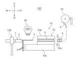
- FIG. 8 is a schematic side view of the fifth station St5.
- the fifth station St5 is provided with an insulating device 51 for insulating the separated drain line 3 .
- the insulation processing device 51 includes a tube reel 52 around which the uncut heat-shrinkable tube 6 is wound, a tube mounting device 53 for inserting the separated drain wire 3 into the heat-shrinkable tube 6, and a drain wire 3 inserted into the heat-shrinkable tube 6. and a heating device 54 for heating the heat-shrinkable tube 6 in the folded state.
- the heat-shrinkable tube 6 is pulled out from the reel by the tube mounting device 53 and cut to a predetermined length by the tube cutter 53a of the tube mounting device 53 .
- the tube mounting device 53 moves the holding portion 53b holding the cut heat-shrinkable tube 6 rearward (toward the fixing clamp 130 side).
- the tube mounting device 53 includes a holding portion moving device 53c that moves the holding portion 53b in the front-rear direction.
- the heating device 54 blows hot air into the holding portion 53b.
- the heat-shrinkable tube 6 is heat-shrunk and the drain wire 3 is insulated.
- the method of insulating the drain wire 3 is not limited to the method of covering the drain wire 3 with the heat-shrinkable tube 6 .
- the insulating treatment of the drain wire 3 may be performed by winding an insulating tape around the drain wire 3, for example.
- the method of covering the drain wire 3 with the heat-shrinkable tube 6 has the advantage of being easily carried out by an automatic machine.
- FIG. 9 is a schematic plan view of the sixth station St6.
- the sixth station St6 includes a bend-back device 61 that bends back the plurality of core wires 4 bent in the separating step, and an alignment device 62 that aligns the drain wire 3 and the plurality of core wires 4. , is provided.
- the bend-returning device 61 is an example of a reverting device for realigning the drain wire 3 and the plurality of core wires 4 separated in the separation step.
- the plurality of core wires 4 that were bent in the separation step are bent back to align the drain wires 3 and the plurality of core wires 4.
- the plurality of core wires 4 (or the drain wires 3) are elastic.
- the return device may be a device that releases the bias of the plurality of core wires 4 (or drain wires 3).
- the unbending device 61 and the aligning device 62 share a part of the configuration and are integrated.
- the multicore shielded cable 1 is stretched in the circumferential direction so that the drain wire 3 and the plurality of core wires 4 are aligned in a predetermined alignment direction, here, in the left-right direction, before the bending-back process and the alignment process.
- a rotation step of rotating is performed.
- the fixing clamp 130 rotates the multicore shielded cable 1 in the circumferential direction to position the drain wire 3 at a predetermined rotational position, here at the 3 o'clock direction in front view. Thereby, as shown in FIG. 9, the drain wire 3 moves to the leftmost among the plurality of core wires.
- the fixing clamp 130 here rotates the multicore shielded cable 1 by 90 degrees.
- the plurality of core wires 4 are positioned to the right of the drain wire 3 .
- the drain wire 3 may be positioned at the right end in the rotating process. Although the details will be described later, by setting the position of the drain line 3 at the left end or the right end, the subsequent steps can be easily performed.
- the bend-back device 61 bends back the drain wire 3 and the plurality of core wires 4 that have been bent by the core wire separation device 33 (here, the core wire 4).
- the unbending device 61 includes a pair of upper and lower rollers 61a (only the lower roller 61a is shown), an opening/closing device (not shown) for the rollers 61a, and a roller moving device 61b.
- the unbending device 61 first drives the opening/closing device to sandwich the exposed root portions of the drain wire 3 and the plurality of core wires 4 (near the remaining sheath 2) between the pair of rollers 61a.
- the roller 61a is configured to rotate in the front-rear direction.
- the roller 61a has a plurality of grooves corresponding to the drain wires 3 and the plurality of core wires 4, respectively. A plurality of grooves are formed along the outer peripheral surface of the roller 61a.
- the bending-back device 61 drives the roller moving device 61b in a state in which the drain wire 3 and the plurality of core wires 4 are sandwiched between the pair of rollers 61a to move the pair of rollers 61a forward.
- the drain wire 3 and the plurality of core wires 4 (particularly the plurality of core wires 4 bent in the separating step) are stretched straight in the front-rear direction along the grooves of the roller 61a.
- the method of bending back the core wire 4 is not limited to the method using the roller as described above.
- the aligning device 62 is configured to align the drain wires 3 and the plurality of core wires 4 in the left-right direction at predetermined intervals. Alignment of the drain wire 3 and the plurality of core wires 4 is performed after the unbending process.
- FIG. 10 is a schematic front view of the sixth station St6, showing a state in which the drain wire 3 and the core wire 4 are aligned.
- the alignment device 62 includes an alignment member 62a for aligning the drain wire 3 and the plurality of core wires 4, and a moving device 62b for bringing the alignment member 62a closer to the drain wire 3 and the plurality of core wires 4. and have.
- the alignment member 62a is a flat member extending in the horizontal direction and the vertical direction, and has a plurality of comb teeth 62a1 arranged in the horizontal direction. A plurality of gaps 62a2 corresponding to the drain wires 3 and the plurality of core wires 4 are provided between the comb teeth 62a1.
- the moving device 62b moves the aligning member 62a in a direction perpendicular to the alignment direction of the core wires, here in the vertical direction, and inserts the drain wires 3 and the plurality of core wires 4 into the plurality of gaps 62a2 of the aligning member 62a.
- the moving device 62b may move the multicore shielded cable 1, or may move both the alignment member 62a and the multicore shielded cable 1.
- the moving device 62b may be configured to move at least one of the aligning member 62a and the multicore shielded cable 1 .
- the plurality of gaps 62a2 are located forward in the direction of movement when the drain wire 3 and the plurality of core wires 4 are inserted (upward in this case, rearward in the direction of movement of the aligning member 62a). It is formed so that it may separate from each other as it goes.
- the plurality of gaps 62a2 are arranged in the left-right direction at predetermined intervals at the front ends of the drain wires 3 and the plurality of core wires 4 in the moving direction (that is, at the ends of the gaps 62a2). As shown in FIG.
- the drain wire 3 and the plurality of core wires 4 are arranged in the horizontal direction at predetermined intervals. This alignment allows the lateral positions of the drain wire 3 and the plurality of core wires 4 to be specified, so that the subsequent process, for example, the transfer process of the multi-core shielded cable 1 to the shuttle 120, can be performed smoothly. .
- the multicore shielded cable 1 is transferred from the transfer device 110 to the shuttle 120.
- the shuttle 120 includes a plurality of individual clamps 120a spaced approximately the same as the aligned drain wires 3 and core wires 4.
- a plurality of individual clamps 120a grip the insulated drain wire 3 and the plurality of core wires 4, respectively.
- each individual clamp 120a is configured to clamp the drain wire 3 or the core wire 4 with elastic force.
- the drain wire 3 and the plurality of core wires 4 are pushed into the plurality of individual clamps 120a by another comb (not shown), for example.
- FIG. 11 the shuttle 120 includes a plurality of individual clamps 120a spaced approximately the same as the aligned drain wires 3 and core wires 4.
- a plurality of individual clamps 120a grip the insulated drain wire 3 and the plurality of core wires 4, respectively.
- each individual clamp 120a is configured to clamp the drain wire 3 or the core wire 4 with elastic force.
- the drain wire 3 and the plurality of core wires 4 are
- the plurality of individual clamps 120a includes an upstream group 120R for gripping the plurality of core wires 3 and 4 exposed at the upstream end of the bent multicore shielded cable 1, and an upstream group 120R. and a downstream group 120L that is arranged downstream of the group 120R in the conveying direction and holds the plurality of core wires 3 and 4 exposed at the downstream end of the bent multicore shielded cable 1. .
- FIG. 11 is a schematic plan view of the seventh station St7.
- the seventh station St7 is provided with a rubber plug mounting device 71 configured to load the tip portion of the core wire 4 and for mounting the rubber plug 7 on the loaded core wire 4.
- the rubber plug mounting device 71 includes a rubber plug supply device 71a and a rubber plug clamp 71b.
- the rubber plug supply device 71a supplies the rubber plug 7 into the rubber plug clamp 71b by, for example, compressed air.
- the rubber plug clamp 71b grips the rubber plug 7 from the outside in the radial direction.
- the shuttle 120 includes a loading device 120b that individually moves a plurality of individual clamps 120a back and forth.
- the loading device 120b individually moves the plurality of individual clamps 120a to individually attach the core wires 4 held by the individual clamps 120a to the rubber stopper mounting device 71 before the coating of the tip of the core wire 4 is stripped off. to load.
- the core wire 4 is inserted into the rubber plug 7 by moving forward together with the individual clamp 120a.
- the shuttle 120 intermittently moves to the left, and the rubber plugs 7 are sequentially attached to the eight ends of the four core wires 4 .
- Such intermittent movement of the shuttle 120 also applies to the stripping process of the core wire, except that the drain wire 3 is also treated.
- the intermittent movement of the shuttle 120 is performed except that the drain wire 3 is also processed and the left end and right end of the multicore shielded cable 1 are processed by different crimping devices 91 and 92. , the same applies to the crimping process.
- FIG. 12 is a schematic plan view of the eighth station St8.
- the eighth station St8 is configured to be loaded with the tip of the drain wire 3 or the core wire 4, and the tip of the loaded drain wire 3 or core wire 4 is stripped.
- a core wire stripping device 81 is provided.
- the loading device 120b of the shuttle 120 individually moves the plurality of individual clamps 120a to individually load the core wire stripping device 81 with the drain wires 3 or the core wires 4 gripped by the individual clamps 120a.
- the core wire stripping device 81 has a pair of stripping blades 81a.
- the drain wire 3 and the plurality of core wires 4 stripped at the ends are cut by a cutter (not shown) of the core wire stripping device 81 so that the positions of the ends are aligned.
- the end positions of the drain wire 3 and the plurality of core wires 4 are specified by the aligning cutting process. As a result, the crimping process can be performed smoothly.
- FIG. 13 is a schematic plan view of the ninth station St9.
- the ninth station St9 is configured to be loaded with the tip of the drain wire 3 or the core wire 4, and the terminal 8 is attached to the tip of the loaded drain wire 3 or core wire 4.
- a right crimping device 91 is provided for crimping.
- a left crimping device 92 is also provided at the ninth station St9.
- the loading device 120b of the shuttle 120 individually moves the plurality of individual clamps 120a to individually press the drain wire 3 or the core wire 4, which is gripped by the individual clamps 120a and whose tip is stripped, to the crimping device 91. Or load 92. Since the configuration of the right crimping device 91 and the configuration of the left crimping device 92 are the same, only the configuration of the right crimping device 91 will be described below.
- the right crimping device 91 includes an applicator 91a, a press (not shown) that presses the applicator 91a, and a terminal reel 91b.
- the applicator 91a includes a crimper (not shown), which is a mold for molding the terminal 8, and an anvil 91a1.
- the crimper and the anvil 91a1 face each other vertically.
- the terminal 8 is supplied from the terminal reel 91b between the crimper and the anvil 91a1, and when the press is driven with the tip of the core wire of the multi-core shielded cable 1 inserted between the crimper and the anvil 91a1, the crimper and the anvil 91a1 are driven.
- the mounting of the rubber plug 7, the stripping of the core wire, and the crimping of the terminal 8 are performed for each core wire in terms of quality control. Therefore, in this embodiment, the drain wire 3 or the core wire 4 is loaded one by one into the rubber plug mounting device 71, the core wire stripping device 81, the right crimping device 91, or the left crimping device 92 by the loading device 120b. In this embodiment, since the right and left positions of the core wire are specified by the alignment process, the mounting of the rubber plug 7, the stripping of the core wire, and the crimping of the terminal 8 can be reliably carried out.
- the position of the drain wire 3 is also specified in the post-process (that is, it is known that the core wire at the left end is the drain wire 3). Therefore, it can be easily determined whether it is the turn to process the drain wire 3 or the turn to process the core wire 4 in the subsequent process. For example, when using a terminal 8 for the drain wire 3 different from that for the core wire 4 in the crimping process, it is necessary to specify the position of the drain wire 3 .
- the attachment of the rubber plug 7, the stripping of the core wires 3 and 4, and the crimping of the terminal 8 must be performed for all the core wires 3 and 4 (all the core wires 4 when the rubber plug 7 is attached). good too. These steps may not be performed on the drain lines 3 and some core lines 4 may not be performed. Exposed portions of the drain wire 3 or core wire 4 not subjected to these steps may be cut off prior to these steps.
- the conveying device for the multicore shielded cable 1 in the processing device 200 may be configured as follows.
- the configuration of the conveying device is not limited to the following.
- FIG. 14 is a rear view of the conveying device for the multicore shielded cable 1.
- the conveying device for the multicore shielded cable 1 includes a cutting device 21, a sheath semi-stripping device 22, a drain wire detecting device 31, a sheath stripping device 32 (drain A rotating device that rotates the multi-core shielded cable 1 based on the circumferential position of the drain wire 3 detected by the wire detection device 31 and positions the drain wire 3 at a predetermined rotational position (here, the 0 o'clock position).
- the second conveying device 119 includes a shuttle 120 having a plurality of individual clamps 120a for respectively holding a plurality of core wires 3 and 4 of the multicore shielded cable 1, and a shuttle conveying device 121 for moving the shuttle 120. .
- the second transport device 119 comprises a plurality of shuttles 120 .
- the first conveying device 110 is provided so as to face the plurality of processing stations St2 to St6, respectively, and is configured to hold a plurality of fixing clamps 130 that hold the multicore shielded cable 1 and each hold the multicore shielded cable 1. and a plurality of transfer clamps 111 that reciprocate between two adjacent fixed clamps 130 out of the plurality of fixed clamps 130 .
- the fixed clamp 130 is an example of a fixed gripping device that grips the multicore shielded cable 1 .
- the plurality of transport clamps 111 of the first transport device 110 are arranged at the same pitch in the transport direction of the multicore shielded cable 1 and reciprocate in the transport direction.
- the clamp moving device 112 of the first conveying device 110 includes a slide rail 112a extending in the conveying direction and engaged with the plurality of conveying clamps 111, a driving unit 112b for moving the plurality of conveying clamps 111 along the slide rail 112a, It has A plurality of fixed clamps 130 as fixed gripping devices are arranged so as to be aligned in the front-rear direction with the respective transfer clamps 111 at the stop position.
- the pitch of the plurality of fixed clamps 130 is the same as the pitch of the plurality of transfer clamps 111 and is constant.
- the two most upstream transport clamps 111 in the transport direction grip the U-shaped multicore shielded cable 1 at two points and move it to a position directly facing the second station St2.
- Two fixing clamps 130 arranged behind the second station St2 grip the transported multi-core shielded cable 1 at two points. After that, the transport clamp 111 returns to the rear of the first station St1 and grips the next multicore shielded cable 1 .
- Other transport clamps 111 and other fixed clamps 130 operate similarly. As a result, a plurality of multicore shielded cables 1 are sequentially transported downstream in the transport direction.
- the shuttle transport device 121 of the second transport device 119 includes a take-up position P0 at which the multicore shielded cable 1 is taken in, a first facing position P1 facing the core wire stripping device 81, and crimping devices (right crimping device 91 and left crimping device 92). ), and in the case of the processing apparatus 200 provided with the rubber plug mounting device 71, the third facing position P3 facing the rubber plug mounting device 71 and the position after the terminal 8 is crimped.
- the shuttle 120 is moved between a release position P4 where the multicore shielded cable 1 is released.
- the shuttle transport device 121 circulates a plurality of shuttles 120 .
- the shuttle transport device 121 may reciprocate or circulate one shuttle 120 .
- the first facing position P1 is the upstream first position where the downstream end of the multicore shielded cable 1 faces the core wire stripping device 81 . and a first downstream facing position where the upstream end of the multicore shielded cable 1 faces the core wire stripping device 81 .
- the second facing position P2 is the upstream second facing position where the downstream end of the multicore shielded cable 1 faces the right crimping device 91 and the left side crimping device 92 where the upstream end of the multicore shielded cable 1 faces. and a second downstream facing position facing the .
- the devices provided in the respective processing stations St7 to St9 operate downstream while the devices provided in the processing stations adjacent to the upstream side are processing the upstream end of the multicore shielded cable 1. configured to machine side edges.
- the right crimping device 91 crimps the terminal 8 to the downstream end of the multicore shielded cable 1 while the core wire stripping device 81 is stripping the upstream end of the multicore shielded cable 1 . Therefore, in the present embodiment, for example, the first downstream facing position and the second upstream facing position are the same position. In this way, the take-up position P0, the third facing position P3, the first facing position P1, the second facing position P2, and the release position P4 may partially overlap.
- the shuttle transport device 121 includes a circulation member 121a to which a plurality of shuttles 120 are fixed and which travels in a loop, and a drive section 121b which circulates the circulation member 121a.
- the circulation member 121a is, for example, an endless belt or chain.
- the circulation member 121a is configured to draw a loop when viewed in the front-rear direction.
- the circulatory movement of the shuttle 120 includes lateral movement between the pick-up position P0, the third facing position P3, the first facing position P1, and the second facing position P2, and the pick-up position P0, the third facing position P3. , a first facing position P1, and a vertical movement to a position lower than the second facing position P2.
- the release position P4 is set in the upper stage of the loop along with the take-up position P0, the third facing position P3, the first facing position P1, and the second facing position P2. It may be set between the lower stage.
- the circulation member 121a may, for example, be arranged along a horizontal plane and configured to draw a loop in plan view.
- the plurality of individual clamps 120a of the shuttle 120 grip the plurality of core wires 3, 4 when the shuttle 120 moves from a position below the take-up position P0 to the take-up position P0.
- the individual clamp 120a has a U-shape with an open top, and holds the drain wire 3 or the core wire 4 inside the U-shape.
- the individual clamp 120a has elasticity so that the core wires 3 and 4 can be inserted inside the U shape and held after insertion.
- the core wires 3 and 4 are pushed into the individual clamps 120a by the upward movement of the shuttle 120 toward the take-up position P0 and the action of the pressing member of the aligning device 62 covering the core wires 3 and 4 from above.
- the processing apparatus 200 includes the cutting device 21, the sheath semi-stripping device 22, the drain wire detecting device 31, the sheath stripping device 32 (including the rotary clamp 32a), the core wire separating device 33, the drain A first conveying device 110 for conveying the multicore shielded cable 1 to the wire straightening device 41, the insulation processing device 51, the bendback device 61, and the alignment device 62, the rubber plug mounting device 71, the core wire stripping device 81, and the crimping device 91. , 92 and a second conveying device 119 for conveying the multicore shielded cable 1 to 92 .
- the second conveying device 119 includes a shuttle 120 having a plurality of individual clamps 120a for respectively holding a plurality of core wires 3 and 4, and a shuttle conveying device 121 for moving the shuttle 120.
- the shuttle conveying device 121 has a take-up position P0 at which the multicore shielded cable 1 is taken in, a third facing position P3 facing the rubber plug mounting device 71, a first facing position P1 facing the core wire stripping device 81, and a crimping device 91. , 92 and a release position P4 where the multicore shielded cable 1 is released after the terminal 8 is crimped.
- the multicore shielded cable 1 can be transported without re-grasping the core wires 3 and 4 during the attachment of the rubber plug 7, the stripping of the core wires 3 and 4, and the crimping of the terminal 8. . Therefore, the positions of the core wires 3 and 4 are stabilized without changing the gripping position. As a result, the mounting of the rubber plug 7, the stripping of the core wires 3 and 4, and the crimping of the terminal 8 can be performed with high quality.
- the shuttle transport device 121 circulates a plurality of shuttles 120 .
- the shuttle 120 can be returned from the release position P4 to the take-up position P0, and the multicore shielded cable 1 is continuously transported.
- productivity can be improved.
- the circulatory movement of the shuttle 120 includes lateral movement between the pick-up position P0, the third facing position P3, the first facing position P1, and the second facing position P2, and the pick-up position P0, the third facing position P3. , a first facing position P1, and a vertical movement to a position lower than the second facing position P2.
- the multiple individual clamps 120a of the shuttle 120 grip the multiple core wires 3, 4 when the shuttle 120 moves from a position below the take-up position P0 to the take-up position P0.
- the core wires 3 and 4 can be gripped by utilizing the vertical movement of the shuttle 120 during its circulating movement, so the process time can be shortened.
- the first transfer device 110 is provided to face the plurality of processing stations St2 to St6, respectively, and includes a plurality of fixing clamps 130 for holding the multicore shielded cable 1, and the multicore shielded cable 1. a plurality of transfer clamps 111 that are configured to grip and reciprocate between two adjacent fixed clamps 130 of the plurality of fixed clamps 130 . Depending on the number of fixed clamps 130, only one transport clamp 111 may be used. According to the processing apparatus 200, in a process that does not require a high degree of positioning for transporting the multicore shielded cable 1 (here, the process of cutting the sheath 2 to the alignment of the core wires 3 and 4), the transport clamp 111 reciprocates. While moving, the multi-core shielded cable 1 is re-gripped. This simplifies the configuration of the transfer device (first transfer device 110) for the multicore shielded cable 1 in this process.
- the multicore shielded cable 1 in a process that does not require a high degree of positioning regarding the transport of the multicore shielded cable 1, the multicore shielded cable 1 is re-clamped to simplify the first transport device 110, and the positional accuracy of the core wires 3 and 4 is improved. (here, from mounting the rubber plug 7 to crimping the terminal 8), the multi-core shielded cable 1 is not re-clamped, and the shuttle 120 is moved while gripping the core wires 3 and 4. As a result, the processing apparatus 200 as a whole is simplified, and the processing quality of the multicore shielded cable 1 is enhanced.
- the plurality of processing stations St2 to St6 are arranged side by side in the conveying direction of the multicore shielded cable 1 by the conveying clamp 111.
- FIG. The processing device 200 is arranged upstream in the transport direction from the plurality of processing stations St2 to St6, and bends the multicore shielded cable 1 into a substantially U shape so that both ends are aligned in the transport direction. (although it may be a dedicated bending device).
- the plurality of fixing clamps 130 are each configured to grip one end of the multicore shielded cable 1 bent by the bending device 110A.
- the devices provided in each of the processing stations St2 to St6 operate on the downstream side while the devices provided in the processing stations adjacent to the upstream side are processing the upstream end portion of the bent multicore shielded cable 1. Process the ends. According to such a configuration, both ends of the multicore shielded cable 1 can be processed simultaneously, so productivity can be improved.
- the plurality of individual clamps 120a of the shuttle 120 includes an upstream group 120R for gripping the plurality of core wires 3, 4 exposed at the upstream end of the bent multicore shielded cable 1, and an upstream group 120R.
- a downstream group 120L arranged downstream in the conveying direction from the side group 120R and holding a plurality of core wires 3 and 4 exposed at the downstream end of the bent multicore shielded cable 1; there is According to such a configuration, both ends of the U-bent multicore shielded cable 1 can be gripped even in the process of conveying the multicore shielded cable 1 by the shuttle 120 .
- the devices provided at the respective processing stations St7 to St9 are arranged upstream of the multicore shielded cable 1 and the device provided at the processing station adjacent to the upstream side. Process the downstream end while processing the side end.
- FIG. 15 is a rear view of a conveying device for a multicore shielded cable 1 according to another embodiment.
- the transfer device for the multicore shielded cable 1 includes a transfer device 140 that receives the multicore shielded cable 1 from the first transfer device 110 and transfers the multicore shielded cable 1 to the second transfer device 119 . may By providing the transfer device 140, direct transfer of the multicore shielded cable 1 from the first transfer device 110 to the second transfer device 119 is eliminated.
- the transfer device 140 is arranged between the fifth station St5 and the sixth station St6.
- the first conveying device 110 conveys the multicore shielded cable 1 from the second station St2 to the transfer device 140 via the fifth station St5.
- the second conveying device 119 receives the multicore shielded cable 1 from the transfer device 140 at the receiving position P0, and conveys it to the tenth station St10.
- the plurality of individual clamps 120a of the second transport device 119 are arranged in multiple positions so that the distance between both ends of the multicore shielded cable 1 is narrower than that of the plurality of fixed clamps 130 of the first transport device 110.
- the core shield cable 1 is gripped.
- the length of the processing apparatus 200 in the conveying direction can be shortened.
- the width of the shuttle 120 in the transport direction can be narrowed.
- the stations St2 to St5 where the first conveying device 110 conveys the multicore shielded cable 1 the distance between both ends of the multicore shielded cable 1 is wide, so there is a degree of freedom and margin in the arrangement of the devices.
- the delivery device 140 shortens the distance between both ends of the shielded multicore cable 1.
- the delivery device 140 is provided with a function of narrowing the space between both ends of the multicore shielded cable 1, so that the device for narrowing the space between both ends of the multicore shielded cable 1 and the delivery device 140 are shared. .
- the transfer device 140 includes a pair of clamps 141 that hold both ends of the multicore shielded cable 1, a drive device 142 that moves the pair of clamps 141 closer to or away from each other, and the clamps 141 and the drive device 142. It includes a moving body 143 to be supported, an elevating device 144 for moving the moving body 143 in the vertical direction, and a slide device 145 for moving the moving body 143 in the transport direction.
- the delivery device 140 moves the moving body 143 above the most downstream transport clamp 111 (moved downstream) by the slide device 145. .
- the transfer device 140 lowers the moving body 143 by the lifting device 144 to a position where the vertical position of the clamp 141 is the same as that of the multicore shielded cable 1 .
- the pair of clamps 141 grip both ends of the multicore shielded cable 1 .
- the distance between the pair of clamps 141 corresponds to the distance between both ends of the multicore shielded cable 1 when it is held by the first conveying device 110 .
- the transfer device 140 raises the moving body 143 when the pair of clamps 141 grip the multicore shielded cable 1 . Further, the transfer device 140 moves the moving body 143 downstream in the transport direction to above the shuttle 120 at the pick-up position P0. During this time, the driving device 142 brings the pair of clamps 141 closer together so that the distance between the pair of clamps 141 corresponds to the distance between both ends of the multicore shielded cable 1 when it is held by the second conveying device 119 . The driving device 142 moves the pair of clamps 141 toward or away from each other so that the distance between the pair of clamps 141 corresponds to the distance between both ends of the multicore shielded cable 1 held by the first conveying device 110.
- the delivery device 140 then descends and delivers the multicore shielded cable 1 to the shuttle 120 at the take-up position P0.
- the driving device 142 rotates the pair of clamps 141 around a rotation axis arranged at a position different from the axis of the multicore shielded cable 1 that is gripped, so that the distance between both ends of the multicore shielded cable 1 is reduced. change the distance.
- the driving device 142 rotates the upstream clamp 141R downstream by 90 degrees around the rotation axis Ar. Further, the driving device 142 rotates the downstream side clamp 141L about the rotation axis Al by 90 degrees to the upstream side. As a result, the distance between both ends of the multicore shielded cable 1 is reduced.
- both ends of the multicore shielded cable 1 are rotated not by the fixing clamp 130 but by the driving device 142, so that the multiple core wires 3 and 4 are arranged in the conveying direction.
- the core wire 4 can be bent back by the bend-back device 61 and the alignment device 62 to align the drain wire 3 and the plurality of core wires 4 .
- the configuration of the delivery device 140 is not limited to the one described above.
- the configuration in which the transfer device 140 changes the distance between both ends of the multicore shielded cable 1 is not limited to the configuration in which the clamp 141 is rotated.
- the transfer device 140 may be configured to change the distance between both ends of the multicore shielded cable 1 by, for example, sliding one or both of the pair of clamps 141 in the conveying direction. The delivery device 140 does not need to move the multicore shielded cable 1 up and down.
- the plurality of individual clamps 120a of the second conveying device 119 are arranged so that the distance between both ends of the multicore shielded cable 1 is narrower than that of the plurality of fixed clamps 130 of the first conveying device 110.
- the multicore shielded cable 1 is gripped in 1, both ends of the multicore shielded cable 1 may be gripped at the same interval as the fixing clamp 130 grips.
- the position of the drain wire 3 is detected after the sheath 2 is semi-stripped, and then the sheath 2 is completely stripped.
- the position of the drain wire 3 may be detected after the sheath 2 is completely stripped.
- the strip length of the sheath 2 is short and the twisting of the core wire does not matter, the untwisting of the core wire in the strip of the sheath 2 may not be performed.
- the straightening process of the drain wire 3 may not be performed.
- the multicore shielded cable 1 including the drain wire 3 and a plurality of core wires 4 is processed.
- the cable to be processed may be a multicore cable that does not include drain wires.
- the multicore cable processing device may be a device for processing a multicore cable having a sheath and a plurality of core wires inserted through the sheath.
- the multicore cable processing device includes a cutting device that forms a cut in the sheath along the circumferential direction, and at least one of the sheath on the tip side and the sheath on the root side of the multicore cable from the cut. a pulling device for moving in the longitudinal direction of the wire to expose the plurality of core wires.
- the multi-core cable processing device further comprises a detection device for detecting the position of a specific core wire among the plurality of core wires in the circumferential direction of the multi-core cable, and a multi-core cable based on the detected position of the specific core wire in the circumferential direction. and a rotating device that rotates the cable and moves the specific core wire to a predetermined circumferential position.
- the specific core wire may be the drain wire, but may be another core wire.
- the multicore cable is rotated based on the circumferential position of the specific core wire detected by the detection device, and the position of the specific core wire is changed from the predetermined circumferential position. can do. Along with this, the positions of the plurality of core wires are determined. This makes it possible to specify the position of each core wire of the multicore cable.
- Multi-core shielded cable (multi-core cable) 2 Sheath 3 Drain wire (core wire) 4 core wire (core wire) 6 Heat-shrinkable tube 7 Rubber stopper (waterproof rubber stopper) 8 terminal 21 cutting device 22 sheath semi-strip device (extraction device) 31 drain wire detection device (detection device) 32 sheath strip device (withdrawal device) 32a rotating clamp (rotating device) 33 core wire separation device (separation device) 41 Drain wire straightening device (straightening device) 51 insulation processing device 53 tube mounting device (insertion device) 54 Heating device 61 Unbending device 62 Aligning device 62a Aligning member 62b Moving device 71 Rubber stopper mounting device 81 Core wire stripping device (stripping device) 91 right crimping device (crimping device) 92 left side crimping device (crimping device) 110 transport device (first transport device) 110A bending device 111 transport clamp (grasping device, moving gripping device) 112 clamp moving device (grasping device moving
Landscapes
- Engineering & Computer Science (AREA)
- Manufacturing & Machinery (AREA)
- Mechanical Engineering (AREA)
- Manufacturing Of Electrical Connectors (AREA)
- Wire Processing (AREA)
- Removal Of Insulation Or Armoring From Wires Or Cables (AREA)
- Processing Of Terminals (AREA)
Abstract
Description
以下、図面を参照しながら、本発明の実施の形態について説明する。まず、ここでの線処理の対象である多芯ケーブル、ここでは、シールドを有する多芯シールドケーブル1について図1を参照しながら説明する。図1は、一例に係る多芯シールドケーブル1の模式的な断面図である。図1に示すように、多芯シールドケーブル1は、シース2と、シース2に挿通されたドレイン線3および複数のコア線4と、シールド5と、を有している。多芯シールドケーブル1は、ドレイン線3と複数のコア線4とシールド5とがシース2によって覆われた電線である。複数のコア線4は、例えば、電気信号を伝達する信号線として使用される。複数のコア線4は、それぞれ、芯線4aと芯線4aを覆う絶縁体の被覆4bとを有している。シールド5は、コア線4を外部のノイズから遮蔽する導体である。シールド5は、複数のコア線4の外側を覆っている。ドレイン線3は、シールド5に電気的に接続されている。ドレイン線3は接地され、これによりシールド5が接地される。ドレイン線3は、複数の細い導体素線からなり、絶縁体による被覆はされていない。図示は省略するが、ドレイン線3と複数のコア線4とはシールド5の内部において撚り合わされている。シールド5は、絶縁体のシース2によって覆われている。コア線4の本数は特に限定されない。以下では、ドレイン線3と複数のコア線4とを特に区別しない場合には、総称して芯線と呼ぶことがある。
以下、ステーション毎に行われる工程の詳細を説明する。以下の説明では、搬送装置110またはシャトル120から見たステーションSt1~St9の方向を前方と呼び、符号Fで表す。左方および右方は、前方に向かって見た左方および右方とする。図面において、F、Rr、L、R、U、Dはそれぞれ、前後左右上下を表している。ただし、これらの方向は説明の都合上のものであり、加工装置200の設置態様等を何ら限定するものではない。例えば、搬送装置110またはシャトル120の移動経路は直線でなくてもよいため、ステーションによって前方が変わることもあり得る。なお、第1ステーションSt1および第10ステーションSt10において行われる工程については、詳細な説明を省略する。
加工装置200における多芯シールドケーブル1の搬送装置は、詳しくは、以下のような構成であってもよい。ただし、搬送装置の構成は、以下のようなものに限定されるわけではない。
図15は、他の実施形態に係る多芯シールドケーブル1の搬送装置の背面図である。なお、以下の他の実施形態の説明でも、上記した実施形態と同じ機能を奏する部材には、同じ符号を使用する。図15に示すように、多芯シールドケーブル1の搬送装置は、第1搬送装置110から多芯シールドケーブル1を受け取り、第2搬送装置119に多芯シールドケーブル1を引き渡す受け渡し装置140を備えていてもよい。受け渡し装置140を設けることにより、第1搬送装置110から第2搬送装置119への多芯シールドケーブル1の直接の受け渡しがなくなる。そのため、第1搬送装置110および第2搬送装置119の待ち時間を削減することができる。この実施形態では、受け渡し装置140は、第5ステーションSt5と第6ステーションSt6との間に配置されている。第1搬送装置110は、第2ステーションSt2から第5ステーションSt5を経て、受け渡し装置140まで多芯シールドケーブル1を搬送する。第2搬送装置119は、引き取り位置P0において受け渡し装置140から多芯シールドケーブル1を引き取り、第10ステーションSt10まで搬送する。
以上、本発明の好適ないくつかの実施形態について説明した。ただし、上記実施形態は例示に過ぎず、他にも種々の実施形態が可能である。例えば、上記した実施形態では、シース2のセミストリップ工程を行った後にドレイン線3の位置を検出し、さらにその後にシース2の全ストリップ工程を行っていた。しかし、例えば、シース2のストリップ長が短く、芯線がばらけるおそれが少ない場合などには、シース2の全ストリップ工程を行った後にドレイン線3の位置を検出してもよい。また、シース2のストリップ長が短く、芯線の撚りが問題にならない場合などには、シース2のストリップにおける芯線の撚り戻しは行われなくてもよい。さらには、シース2のストリップ長が短く、露出したドレイン線3が短い場合などには、ドレイン線3の矯正工程は行われなくてもよい。
2 シース
3 ドレイン線(芯線)
4 コア線(芯線)
6 熱収縮チューブ
7 ゴム栓(防水ゴム栓)
8 端子
21 切込装置
22 シースセミストリップ装置(引き抜き装置)
31 ドレイン線検出装置(検出装置)
32 シースストリップ装置(引き抜き装置)
32a 回転クランプ(回転装置)
33 コア線分離装置(分離装置)
41 ドレイン線矯正装置(矯正装置)
51 絶縁処理装置
53 チューブ装着装置(挿入装置)
54 加熱装置
61 曲げ戻し装置
62 整列装置
62a 整列部材
62b 移動装置
71 ゴム栓装着装置
81 芯線ストリップ装置(ストリップ装置)
91 右側圧着装置(圧着装置)
92 左側圧着装置(圧着装置)
110 搬送装置(第1搬送装置)
110A 屈曲装置
111 搬送クランプ(把持装置、移動把持装置)
112 クランプ移動装置(把持装置移動装置)
119 第2搬送装置
120 シャトル(キャリア)
120a 個別クランプ(把持部材)
121 シャトル搬送装置(キャリア移動装置)
120b 装填装置
130 固定クランプ(固定把持装置)
140 受け渡し装置
141 クランプ(把持部材)
142 駆動装置
150 制御装置
200 加工装置
St2~St9 ステーション(加工ステーション、他の加工ステーション)
Claims (20)
- シースと前記シースに挿通された複数の芯線とを有する多芯ケーブルを加工する装置であって、
周方向に沿った切れ目を前記シースに形成する切込装置と、
前記切れ目よりも前記多芯ケーブルの先端側のシースと根元側のシースとのうちの少なくとも一方を前記多芯ケーブルの長手方向に移動させて、前記複数の芯線を露出させる引き抜き装置と、
前記複数の芯線のうち特定の芯線の前記多芯ケーブルの周方向に関する位置を検出する検出装置と、
前記検出された前記特定の芯線の周方向の位置に基づいて前記多芯ケーブルを回転させ、前記特定の芯線を予め定められた周方向の位置に移動させる回転装置と、を備えた、
多芯ケーブルの加工装置。 - 前記複数の芯線は、ドレイン線と複数のコア線からなり、
前記特定の芯線は、前記ドレイン線であり、
前記検出されたドレイン線の周方向の位置に基づき、前記ドレイン線および前記複数のコア線のうちの少なくとも一方を付勢することによって、前記ドレイン線と前記複数のコア線とを分離する分離装置と、
前記分離されたドレイン線を絶縁処理する絶縁処理装置と、
前記切込装置、前記引き抜き装置、前記検出装置、前記回転装置、前記分離装置、および前記絶縁処理装置に前記多芯ケーブルを搬送する第1搬送装置と、をさらに備えた、
請求項1に記載の多芯ケーブルの加工装置。 - 前記絶縁処理の前に、前記分離されたドレイン線を周方向に撚りながら引っ張りテンションを加えることにより矯正する矯正装置をさらに備えている、
請求項2に記載の多芯ケーブルの加工装置。 - 前記絶縁処理装置は、
前記分離されたドレイン線を熱収縮チューブに挿入する挿入装置と、
前記ドレイン線が挿入された状態の前記熱収縮チューブを加熱する加熱装置と、を備えている、
請求項2または3に記載の多芯ケーブルの加工装置。 - 前記引き抜き装置は、前記先端側のシースが前記根元側のシースに対して周方向に回転するように前記先端側のシースおよび前記根元側のシースのうちの少なくとも一方を回転させながら、前記先端側のシースを引き抜き、前記複数の芯線の撚りをほどくように構成されている、
請求項1~4のいずれか一つに記載の多芯ケーブルの加工装置。 - 前記引き抜き装置は、
前記複数の芯線の一部が露出し、かつ、前記複数の芯線の他の一部に前記先端側のシースが残るように前記先端側のシースを引き抜くセミストリップを、前記検出装置による前記特定の芯線の検出よりも前に行い、
前記先端側のシースを前記複数の芯線から離脱させる全ストリップを、前記検出装置による前記特定の芯線の検出よりも後に行うように構成されている、
請求項1~5のいずれか一つに記載の多芯ケーブルの加工装置。 - 前記複数の芯線を所定の間隔で並ばせる整列装置をさらに備え、
前記整列装置は、
複数の櫛歯を有し、前記複数の芯線に対応した複数の隙間が前記櫛歯同士の間に設けられた整列部材と、
前記整列部材および前記多芯ケーブルのうちの少なくとも一方を移動させ、前記複数の芯線を前記整列部材の前記複数の隙間にそれぞれ挿入する移動装置と、を備え、
前記複数の隙間は、前記複数の芯線が挿入される際の移動方向前方に向かうほど互いに離れるように形成され、前記移動方向の前端において前記所定の間隔で並んでいる、
請求項1~6のいずれか一つに記載の多芯ケーブルの加工装置。 - それぞれ1本の前記芯線を把持可能な複数の把持部材と、
前記芯線の先端部が装填されるように構成され、装填された前記芯線の先端部の被覆を剥くストリップ装置と、
前記複数の把持部材を個別に移動させて、前記把持部材に把持された前記芯線を個別に前記ストリップ装置に装填する装填装置と、をさらに備えている、
請求項1~7のいずれか一つに記載の多芯ケーブルの加工装置。 - 前記芯線の先端部が装填されるように構成され、装填された前記芯線の先端部に端子を圧着する圧着装置をさらに備え、
前記装填装置は、前記複数の把持部材を個別に移動させて、前記把持部材に把持されるとともに先端部の被覆が剥かれた前記芯線を、個別に前記圧着装置に装填するように構成されている、
請求項8に記載の多芯ケーブルの加工装置。 - 前記複数の芯線は、複数のコア線を含み、
前記コア線の先端部が装填されるように構成され、装填された前記コア線に防水ゴム栓を装着するゴム栓装着装置をさらに備え、
前記装填装置は、前記コア線の先端部の被覆が剥かれる前に、前記複数の把持部材を個別に移動させて、前記把持部材に把持された前記コア線を個別に前記ゴム栓装着装置に装填するように構成されている、
請求項8または9に記載の多芯ケーブルの加工装置。 - 前記切込装置、前記引き抜き装置、前記検出装置、および前記回転装置のうちの少なくとも1つが設けられた加工ステーションと、
前記加工ステーションと所定方向に並んで配置され、前記切込装置、前記引き抜き装置、前記検出装置、および前記回転装置のうちの他の少なくとも1つが設けられた他の加工ステーションと、
前記切込装置、前記引き抜き装置、前記検出装置、および前記回転装置に前記多芯ケーブルを搬送する第1搬送装置と、をさらに備え、
前記第1搬送装置は、
一端と他端とが前記所定方向に並ぶように曲げられた前記多芯ケーブルを把持する把持装置と、
前記把持装置を前記所定方向に移動させる把持装置移動装置と、を備え、
前記他の加工ステーションに設けられた装置は、前記加工ステーションに設けられた装置が前記多芯ケーブルの前記一端を加工しているときに前記他端を加工する、
請求項1~10のいずれか一つに記載の多芯ケーブルの加工装置。 - 前記切込装置、前記引き抜き装置、前記検出装置、および前記回転装置に前記多芯ケーブルを搬送する第1搬送装置と、
前記芯線の先端部が装填されるように構成され、装填された前記芯線の先端部の被覆を剥くストリップ装置と、
前記芯線の先端部が装填されるように構成され、前記ストリップ装置によって前記被覆が剥かれた芯線の先端部に端子を圧着する圧着装置と、
前記ストリップ装置および前記圧着装置に前記多芯ケーブルを搬送する第2搬送装置と、をさらに備え、
前記第2搬送装置は、
それぞれ1本の前記芯線を把持可能な複数の把持部材を備えたキャリアと、
前記多芯ケーブルを引き取る引き取り位置と、前記ストリップ装置に対向した第1対向位置と、前記圧着装置に対向した第2対向位置と、前記端子が圧着された後の前記多芯ケーブルを離すリリース位置との間で前記キャリアを移動させるキャリア移動装置と、を備えている、
請求項1~11のいずれか一つに記載の多芯ケーブルの加工装置。 - 前記第2搬送装置は、複数の前記キャリアを備え、
前記キャリア移動装置は、前記複数のキャリアを循環移動させる、
請求項12に記載の多芯ケーブルの加工装置。 - 前記キャリアの循環移動は、前記引き取り位置、前記第1対向位置、および前記第2対向位置の間の横移動と、前記引き取り位置、前記第1対向位置、および前記第2対向位置よりも下方位置との間の上下移動とを含む循環移動であり、
前記キャリアの前記複数の把持部材は、前記キャリアが前記引き取り位置よりも下方位置から前記引き取り位置に移動するときに前記複数の芯線を把持する、
請求項13に記載の多芯ケーブルの加工装置。 - 前記切込装置、前記引き抜き装置、前記検出装置、および前記回転装置のうちの1つ以上が設けられた加工ステーションを複数備え、
前記第1搬送装置は、
前記複数の加工ステーションにそれぞれ対向するように設けられ、前記多芯ケーブルを把持する複数の固定把持装置と、
それぞれ前記多芯ケーブルを把持するように構成され、前記複数の固定把持装置のうち隣り合った2つの固定把持装置の間を往復移動する1つまたは複数の移動把持装置と、を備えている、
請求項12~14のいずれか一つに記載の多芯ケーブルの加工装置。 - 前記第1搬送装置から前記多芯ケーブルを受け取り、前記第2搬送装置に前記多芯ケーブルを引き渡す受け渡し装置をさらに備えている、
請求項15に記載の多芯ケーブルの加工装置。 - 前記複数の加工ステーションは、前記移動把持装置による前記多芯ケーブルの搬送方向に並んで配置され、
前記複数の加工ステーションよりも前記搬送方向の上流に配置され、両端が前記搬送方向に並ぶように前記多芯ケーブルを略U字に曲げる屈曲装置をさらに備え、
前記複数の固定把持装置は、それぞれ、前記屈曲装置によって曲げられた前記多芯ケーブルの一端を把持するように構成され、
前記各加工ステーションに設けられた装置は、上流側に隣接する加工ステーションに設けられた装置が前記曲げられた前記多芯ケーブルの上流側の端部を加工しているときに下流側の端部を加工する、
請求項15または16に記載の多芯ケーブルの加工装置。 - 前記キャリアの前記複数の把持部材は、
前記曲げられた多芯ケーブルの上流側の端部に露出している前記複数の芯線を把持する上流側グループと、
前記上流側グループよりも前記搬送方向の下流に配置され、前記曲げられた多芯ケーブルの下流側の端部に露出している前記複数の芯線を把持する下流側グループと、を含んでいる、
請求項17に記載の多芯ケーブルの加工装置。 - 前記複数の把持部材は、前記複数の固定把持装置によって把持されるよりも前記多芯ケーブルの両端の間隔が狭くなるように前記多芯ケーブルを把持する、
請求項18に記載の多芯ケーブルの加工装置。 - 前記第1搬送装置から前記多芯ケーブルを受け取り、前記第2搬送装置に前記多芯ケーブルを引き渡す受け渡し装置をさらに備え、
前記受け渡し装置は、
前記多芯ケーブルの両端をそれぞれ把持する一対の把持部材と、
前記一対の把持部材を接近または離反させ、前記一対の把持部材の間の距離を、前記第1搬送装置に把持されているときの前記多芯ケーブルの両端間の距離に対応させ、または、前記第2搬送装置に把持されるときの前記多芯ケーブルの両端間の距離に対応させる駆動装置と、を備えている、
請求項19に記載の多芯ケーブルの加工装置。
Priority Applications (5)
| Application Number | Priority Date | Filing Date | Title |
|---|---|---|---|
| JP2023554662A JP7659077B2 (ja) | 2021-10-14 | 2022-10-14 | 多芯ケーブルの加工装置 |
| US18/700,824 US20260058428A1 (en) | 2021-10-14 | 2022-10-14 | Multicore cable processing apparatus |
| CN202280068714.9A CN118104091A (zh) | 2021-10-14 | 2022-10-14 | 多芯线缆的加工装置 |
| EP22881123.8A EP4418475A4 (en) | 2021-10-14 | 2022-10-14 | Multicore cable processing device |
| JP2025051496A JP2025108454A (ja) | 2021-10-14 | 2025-03-26 | ケーブル加工装置 |
Applications Claiming Priority (2)
| Application Number | Priority Date | Filing Date | Title |
|---|---|---|---|
| JP2021-169027 | 2021-10-14 | ||
| JP2021169027 | 2021-10-14 |
Publications (1)
| Publication Number | Publication Date |
|---|---|
| WO2023063428A1 true WO2023063428A1 (ja) | 2023-04-20 |
Family
ID=85987803
Family Applications (1)
| Application Number | Title | Priority Date | Filing Date |
|---|---|---|---|
| PCT/JP2022/038481 Ceased WO2023063428A1 (ja) | 2021-10-14 | 2022-10-14 | 多芯ケーブルの加工装置 |
Country Status (5)
| Country | Link |
|---|---|
| US (1) | US20260058428A1 (ja) |
| EP (1) | EP4418475A4 (ja) |
| JP (2) | JP7659077B2 (ja) |
| CN (1) | CN118104091A (ja) |
| WO (1) | WO2023063428A1 (ja) |
Cited By (2)
| Publication number | Priority date | Publication date | Assignee | Title |
|---|---|---|---|---|
| EP4513688A1 (en) * | 2023-08-24 | 2025-02-26 | The Boeing Company | Automated cable wire processing |
| KR20250101622A (ko) * | 2023-12-27 | 2025-07-04 | (주)유니코어텍 | 와이어-터미널 연결용 어플리케이터 |
Citations (3)
| Publication number | Priority date | Publication date | Assignee | Title |
|---|---|---|---|---|
| JP2009245703A (ja) * | 2008-03-31 | 2009-10-22 | Shinmaywa Industries Ltd | 電線処理装置 |
| JP2016123215A (ja) | 2014-12-25 | 2016-07-07 | 矢崎総業株式会社 | 熱収縮チューブ取付装置及び熱収縮チューブ取付方法 |
| JP2021009053A (ja) * | 2019-06-28 | 2021-01-28 | 矢崎総業株式会社 | 端子の外観検査装置 |
Family Cites Families (4)
| Publication number | Priority date | Publication date | Assignee | Title |
|---|---|---|---|---|
| US11070007B2 (en) * | 2018-11-19 | 2021-07-20 | The Boeing Company | System configured to position a tip of a cable |
| DE102019130308A1 (de) * | 2019-03-29 | 2020-10-01 | Metzner Holding GmbH | Vorrichtung und Verfahren zur Montage eines elektrischen Steckverbinders |
| DE102019119725A1 (de) * | 2019-06-25 | 2020-12-31 | Metzner Maschinenbau Gmbh | Verfahren, Vorrichtung und System zur Konfektionierung eines elektrischen Kabels |
| EP4250503A4 (en) * | 2020-11-17 | 2024-05-15 | ShinMaywa Industries, Ltd. | CENTRAL WIRE SEPARATION DEVICE |
-
2022
- 2022-10-14 JP JP2023554662A patent/JP7659077B2/ja active Active
- 2022-10-14 CN CN202280068714.9A patent/CN118104091A/zh active Pending
- 2022-10-14 EP EP22881123.8A patent/EP4418475A4/en active Pending
- 2022-10-14 WO PCT/JP2022/038481 patent/WO2023063428A1/ja not_active Ceased
- 2022-10-14 US US18/700,824 patent/US20260058428A1/en active Pending
-
2025
- 2025-03-26 JP JP2025051496A patent/JP2025108454A/ja active Pending
Patent Citations (3)
| Publication number | Priority date | Publication date | Assignee | Title |
|---|---|---|---|---|
| JP2009245703A (ja) * | 2008-03-31 | 2009-10-22 | Shinmaywa Industries Ltd | 電線処理装置 |
| JP2016123215A (ja) | 2014-12-25 | 2016-07-07 | 矢崎総業株式会社 | 熱収縮チューブ取付装置及び熱収縮チューブ取付方法 |
| JP2021009053A (ja) * | 2019-06-28 | 2021-01-28 | 矢崎総業株式会社 | 端子の外観検査装置 |
Non-Patent Citations (1)
| Title |
|---|
| See also references of EP4418475A4 |
Cited By (3)
| Publication number | Priority date | Publication date | Assignee | Title |
|---|---|---|---|---|
| EP4513688A1 (en) * | 2023-08-24 | 2025-02-26 | The Boeing Company | Automated cable wire processing |
| KR20250101622A (ko) * | 2023-12-27 | 2025-07-04 | (주)유니코어텍 | 와이어-터미널 연결용 어플리케이터 |
| KR102853312B1 (ko) * | 2023-12-27 | 2025-09-01 | (주)유니코어텍 | 와이어-터미널 연결용 어플리케이터 |
Also Published As
| Publication number | Publication date |
|---|---|
| JP7659077B2 (ja) | 2025-04-08 |
| EP4418475A1 (en) | 2024-08-21 |
| JPWO2023063428A1 (ja) | 2023-04-20 |
| CN118104091A (zh) | 2024-05-28 |
| EP4418475A4 (en) | 2025-02-19 |
| US20260058428A1 (en) | 2026-02-26 |
| JP2025108454A (ja) | 2025-07-23 |
Similar Documents
| Publication | Publication Date | Title |
|---|---|---|
| JP2025108454A (ja) | ケーブル加工装置 | |
| CN104638497B (zh) | 用于加工多芯线缆的设备 | |
| US4196510A (en) | Apparatus and method for production of wire leads | |
| US20130048141A1 (en) | Feeding wire-ends to processing units | |
| US6289944B1 (en) | Method and equipment for the treatment and twisting together of a conductor pair | |
| EP3979265B1 (en) | Electric cable processing device | |
| US4183383A (en) | Wire shaping mechanism for production of wire leads | |
| US20060179908A1 (en) | Method and device for processing a wire | |
| EP0813271A2 (en) | Wire end alignment assembly for wire crimping apparatus | |
| KR100284380B1 (ko) | 전선처리장치 | |
| JP2916048B2 (ja) | 電線の端末処理装置 | |
| US20240347233A1 (en) | Sequential twisting device | |
| EP0765535B1 (en) | A machine and method for producing electrical harnesses | |
| JP6949788B2 (ja) | 端子圧着装置及び端子圧着方法 | |
| US12451271B2 (en) | Multi-station machine for producing hybrid electrical wiring | |
| IT201900002377A1 (it) | Impianto ibrido automatizzato per il cablaggio di connettori | |
| EP0365137A1 (en) | Method of making an electrical harness | |
| EP4604336A1 (en) | Multi-core shielded cable machining device | |
| EP0601474B1 (en) | Wire-length measuring apparatus | |
| EP0708506A2 (en) | Feed assembly for connector termination apparatus | |
| JP2908717B2 (ja) | 丸形二芯電源コードへのプラグ端子の圧着方法及びその装置 | |
| JPH0487112A (ja) | 電線の加工機械 | |
| JPH11219628A (ja) | 電線の端末処理装置 | |
| JPH09115344A (ja) | ワイヤーハーネス用フラット電線及びその製造 | |
| CN121863165A (zh) | 一种全自动打端插壳绞线设备 |
Legal Events
| Date | Code | Title | Description |
|---|---|---|---|
| 121 | Ep: the epo has been informed by wipo that ep was designated in this application |
Ref document number: 22881123 Country of ref document: EP Kind code of ref document: A1 |
|
| ENP | Entry into the national phase |
Ref document number: 2023554662 Country of ref document: JP Kind code of ref document: A |
|
| WWE | Wipo information: entry into national phase |
Ref document number: 202280068714.9 Country of ref document: CN |
|
| WWE | Wipo information: entry into national phase |
Ref document number: 2022881123 Country of ref document: EP |
|
| NENP | Non-entry into the national phase |
Ref country code: DE |
|
| ENP | Entry into the national phase |
Ref document number: 2022881123 Country of ref document: EP Effective date: 20240514 |