WO2023068243A1 - 車両用エアコン装置 - Google Patents
車両用エアコン装置 Download PDFInfo
- Publication number
- WO2023068243A1 WO2023068243A1 PCT/JP2022/038681 JP2022038681W WO2023068243A1 WO 2023068243 A1 WO2023068243 A1 WO 2023068243A1 JP 2022038681 W JP2022038681 W JP 2022038681W WO 2023068243 A1 WO2023068243 A1 WO 2023068243A1
- Authority
- WO
- WIPO (PCT)
- Prior art keywords
- air
- heater
- door
- air conditioner
- evaporator
- Prior art date
- Legal status (The legal status is an assumption and is not a legal conclusion. Google has not performed a legal analysis and makes no representation as to the accuracy of the status listed.)
- Ceased
Links
Images


Classifications
-
- B—PERFORMING OPERATIONS; TRANSPORTING
- B60—VEHICLES IN GENERAL
- B60H—ARRANGEMENTS OF HEATING, COOLING, VENTILATING OR OTHER AIR-TREATING DEVICES SPECIALLY ADAPTED FOR PASSENGER OR GOODS SPACES OF VEHICLES
- B60H1/00—Heating, cooling or ventilating devices
- B60H1/00642—Control systems or circuits; Control members or indication devices for heating, cooling or ventilating devices
- B60H1/00664—Construction or arrangement of damper doors
- B60H1/00671—Damper doors moved by rotation; Grilles
- B60H1/00678—Damper doors moved by rotation; Grilles the axis of rotation being in the door plane, e.g. butterfly doors
-
- B—PERFORMING OPERATIONS; TRANSPORTING
- B60—VEHICLES IN GENERAL
- B60H—ARRANGEMENTS OF HEATING, COOLING, VENTILATING OR OTHER AIR-TREATING DEVICES SPECIALLY ADAPTED FOR PASSENGER OR GOODS SPACES OF VEHICLES
- B60H1/00—Heating, cooling or ventilating devices
- B60H1/00007—Combined heating, ventilating, or cooling devices
- B60H1/00021—Air flow details of HVAC devices
- B60H1/00035—Air flow details of HVAC devices for sending an air stream of uniform temperature into the passenger compartment
- B60H1/0005—Air flow details of HVAC devices for sending an air stream of uniform temperature into the passenger compartment the air being firstly cooled and subsequently heated or vice versa
-
- B—PERFORMING OPERATIONS; TRANSPORTING
- B60—VEHICLES IN GENERAL
- B60H—ARRANGEMENTS OF HEATING, COOLING, VENTILATING OR OTHER AIR-TREATING DEVICES SPECIALLY ADAPTED FOR PASSENGER OR GOODS SPACES OF VEHICLES
- B60H1/00—Heating, cooling or ventilating devices
- B60H1/00007—Combined heating, ventilating, or cooling devices
- B60H1/00021—Air flow details of HVAC devices
- B60H2001/0015—Temperature regulation
- B60H2001/00164—Temperature regulation with more than one by-pass
-
- B—PERFORMING OPERATIONS; TRANSPORTING
- B60—VEHICLES IN GENERAL
- B60H—ARRANGEMENTS OF HEATING, COOLING, VENTILATING OR OTHER AIR-TREATING DEVICES SPECIALLY ADAPTED FOR PASSENGER OR GOODS SPACES OF VEHICLES
- B60H1/00—Heating, cooling or ventilating devices
- B60H1/00642—Control systems or circuits; Control members or indication devices for heating, cooling or ventilating devices
- B60H1/00664—Construction or arrangement of damper doors
- B60H2001/00721—Air deflecting or air directing means
Definitions
- the present invention relates to a vehicle air conditioner for adjusting the temperature inside the vehicle.
- Patent Document 1 Japanese Patent Document 1
- a vehicle air conditioner disclosed in Patent Document 1 is provided with an evaporator for cooling air and a heater for warming air inside a case.
- the vehicle air conditioner has an air mix door that is rotatably provided between the evaporator and the heater and that can adjust the amount of air passing through the heater.
- a guide portion is provided on the upper surface of the air mix door so as to guide the air flowing along the air mix door in a predetermined direction.
- the vehicle air conditioner is equipped with multiple air outlets toward the passenger compartment.
- the multiple outlets are a defroster outlet for blowing air toward the windshield, a vent outlet for blowing air toward the upper body of the occupant, and a foot outlet for blowing air toward the feet of the occupant. and an outlet.
- Each outlet is provided with an opening/closing door for opening and closing the respective outlet.
- the air mix door can be moved from a full hot position that maximizes the amount of air passing through the heater to a full cool position that minimizes the amount of air passing through the heater.
- a position between the full hot position and the full cool position can be referred to as a temperature conditioning position in which a portion of the air passing through the evaporator bypasses the heater.
- the air mix door is in one of the full hot, full cool and temperature conditioning positions.
- An object of the present invention is to provide a vehicle air conditioner with improved quietness.
- an evaporator (22) capable of cooling air and a heater (23) capable of warming the air that has passed through the evaporator (22) are placed in a case (21, 21C) through which air can pass.
- an air mix door (24, 24A) capable of adjusting the ratio of the air passing through the heater (23) and the air bypassing the heater (23), wherein
- the air mix door (24, 24A) extends substantially orthogonally with respect to the flow direction of the air bypassing the heater (23), and is rotatably provided on the case (21, 21C).
- the butterfly door portion (30) has a full cool position where the ratio of air bypassing the heater (23) is maximized, a full hot position where the ratio of air passing through the heater (23) is maximized, and the and a temperature conditioning position between the full cool position and the full hot position where a portion of the air passing through the evaporator (22) bypasses the heater (23).
- a flow path (R2) between doors is formed,
- the butterfly door portion (30) is provided with a guide portion (41) for guiding the air flowing through the heater-to-door flow path (R2) in a predetermined direction. be done.
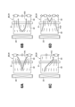
- FIG. 1 is a rear view of a vehicle air conditioner according to Embodiment 1.
- FIG. FIG. 2 is a cross-sectional view of the vehicle air conditioner shown in FIG. 1 as viewed from the side; 3 is a cross-sectional view taken along line 3-3 of FIG. 2;
- FIG. 4A is a diagram for explaining a vehicle air conditioner in a fully cool state, 4B is a diagram for explaining a vehicle air conditioner in a temperature harmonized state, and 4C is a diagram for explaining a vehicle air conditioner in a full hot state.
- is. 4 is a bottom view of the butterfly door shown in FIG. 3;
- FIG. 10 is a cross-sectional view of the vehicle air conditioner according to the second embodiment as viewed from the side
- FIG. 11 is a cross-sectional view of a vehicle air conditioner according to a third embodiment as viewed from the side
- FIG. 11 is a cross-sectional view of a vehicle air conditioner according to Embodiment 4 as viewed from the side
- FIG. 11 is a cross-sectional view of a vehicle air conditioner according to Embodiment 5 as viewed from the side
- FIG. 11 is a cross-sectional view of a vehicle air conditioner according to Embodiment 6 as viewed from the side
- front and rear refer to front and rear with respect to the traveling direction of the vehicle
- left and right refer to left and right with respect to the occupant of the vehicle.
- Fr indicates the front, Rr the rear, Le the left, Ri the right, Up the top, and Dn the bottom.
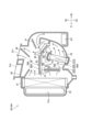
- a vehicle air conditioner 10 (hereinafter abbreviated as "air conditioner 10") is arranged in the front portion of the passenger compartment so as to extend in the left-right direction.
- the air conditioner 10 includes a blower unit 11 capable of taking in and blowing air inside and/or outside the vehicle, a temperature control unit 20 capable of adjusting the blown air sent from the blower unit 11 to a predetermined temperature, have
- the temperature control unit 20 includes a case 21 through which air can pass, an evaporator 22 capable of cooling air, a heater 23 capable of warming the air passing through the evaporator 22, and the air passing through the heater 23.
- An air mix door 24 capable of adjusting the ratio of air bypassing the heater 23 is accommodated.
- the case 21 also has an inlet 21a through which the air blown from the blower unit 11 (FIG. 1) is introduced, a defroster outlet 21d for blowing out the air toward the windshield, and a A vent outlet 21v for blowing air and a foot outlet 21f for blowing air toward the feet of the occupant are formed.
- the case 21 includes a first shutter 25 movably provided to open and close the defroster outlet 21d, a second shutter 26 movably provided to open and close the vent outlet 21v, and a foot. and a third shutter 27 movably provided to open and close the outlet 21f.
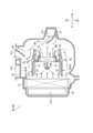
- a plurality of flow paths are formed through which the air that has passed through the evaporator 22 passes.
- a flow path passing through the evaporator 22 and directly directed to the outlets 21d, 21v, and 21f is a cold air flow path R1
- a flow path passing between the air mix door 24 and the upper part of the heater 23 is a heater-door flow path.
- R2 a flow path passing through the heater 23 is a hot air flow path R3; It is called mix channel R4.
- the area near the second shutter 26 and the third shutter 27 in the cold air flow path R1 may become a second mix flow path as an area where the air that has flowed through the mix flow path R4 is mixed.
- the interior of the case 21 is partitioned into two left and right rooms by a partition wall 29 . These two rooms are provided with air mix doors 24, 24, respectively.
- air mix doors 24, 24, respectively By partitioning the inside of the case 21 into two sections and providing air mix doors 24, 24 in each section, it is possible to blow air having different temperatures to, for example, a driver seat passenger and a passenger seat passenger.
- the inside of the case 21 does not necessarily have to be partitioned. Moreover, the inside of the case 21 may be divided into three or more sections. When it is divided into three or more sections, it is possible to blow air of different temperatures not only to the left and right but also to the top and bottom.
- One evaporator 22 is provided so as to be substantially orthogonal to the direction of air flow (the direction from left to right in the drawing).
- a refrigerant flows through the evaporator 22, and the air passing through the evaporator 22 is cooled by heat exchange with the refrigerant.
- a hot water heater through which hot water flows or an electric heater that generates heat when energized can be used. Also, both of these can be used.
- the air mix door 24 is composed of a butterfly door portion 30. That is, in the air conditioner device 10 shown in FIG. 2, the air mix door 24 can also be said to indicate the butterfly door portion 30 .
- the butterfly door portion 30 includes a rotary shaft 31 extending in the lateral direction with respect to air flowing in the longitudinal direction and provided above the heater 23 , and a plate extending upstream of the heater 23 from the rotary shaft 31 .
- a first closing plate 32 capable of adjusting the amount of air passing through, and a second closing plate 33 extending downstream of the heater 23 from the rotating shaft 31 and capable of adjusting the amount of air passing through the heater 23. have.
- the butterfly door portion 30 has an obtuse V shape, and the first closing plate 32 and the second closing plate 33 extend in different directions from the rotating shaft 31 .
- a guide portion 41 is provided continuously from the surface of the first closing plate 32 facing the heater 23 to the surface of the second closing plate 33 facing the heater 23 to guide the direction of air flow.
- the guide portion 41 can guide the air flowing through the heater-door passage R2 in a predetermined direction.
- the rotating shaft 31 is rotated by the motor, for example, when the control unit energizes the motor.
- the control section energizes the motor so as to adjust the position of the butterfly door section 30 based on the set temperature or the like.
- the second closing plate 33 extends from the rotating shaft 31 in a direction away from the vent outlet 21v.
- the guide portion 41 is formed by ribs integrally raised from the butterfly door portion 30 .
- the guide part 41 preferably has a length equal to or longer than half the total length of the first closing plate 32 and/or preferably has a length equal to or longer than half the total length of the second closing plate 33 . This is to guide the air smoothly and reliably.
- the height of the guide portion 41 is preferably half or less of the length from the rotating shaft 31 to the heater 23. This is because a smooth air flow can be ensured by suppressing clogging of the heater-door channel R2 by the guide portion 41 and ensuring a large channel area.
- Two guide portions 41 , 41 are provided in each of the butterfly door portions 30 , 30 .
- the two guide portions 41 extend in the front-rear direction so as to face each other, the width gradually narrows from the upstream end toward the downstream, and the guide portions 41 extend substantially parallel from the middle.
- the guide portion 41 may be formed only on either the first closing plate 32 or the second closing plate 33 .
- a defroster outlet 21 d and a vent outlet 21 v are formed in the upper part of the case 21
- a foot outlet 21 f is formed in the lower part of the case 21 .
- Each of the outlets 21d, 21v, and 21f may directly face the interior of the vehicle, or may be configured to blow air into the interior of the vehicle via a duct or the like.
- the first to third shutters 25 to 27 are operated by motors, for example.
- a control unit connected to the motor energizes the motor in accordance with the set temperature, etc., and adjusts the opening and closing of the first to third shutters 25 to 27 and the degree of opening when the shutters are open.
- 4A shows the air conditioner 10 in a state in which the heater-door channel R2 and the hot air channel R3 are closed. In this state, the air that has passed through the evaporator 22 goes to the vent outlet 21v without passing through the heater 23 . That is, in the state shown in 4A, the ratio of air bypassing the heater 23 is maximized. This state is called a full cool state, and the position of the butterfly door portion 30 in the full cool state is called a full cool position.
- the vent outlet 21v In the full-cool state, for example, the vent outlet 21v is fully opened, and the defroster outlet 21d and the foot outlet 21f are fully closed. In this case, all of the air that has passed through the evaporator 22 is blown into the vehicle interior through the vent outlet 21v. The air passing through the vent outlet 21v is blown toward the passenger's upper body.
- 4B shows the air conditioner 10 with the cold air flow path R1, the heater-door flow path R2, and the hot air flow path R3 opened.
- the air that has passed through the evaporator 22 passes through the cold air flow path R1, the heater-door flow path R2, and the hot air flow path R3, and heads toward the vent outlet 21v or the foot outlet 21f. That is, in the state shown in 4B, the temperature is adjusted by the ratio of the air that has passed through only the evaporator 22 and the air that has passed through the heater 23 .
- This state is called a temperature regulated state
- the position of the butterfly door portion 30 in the temperature regulated state is called a temperature regulated position.
- the vent outlet 21v and the foot outlet 21f are half-opened, and the defroster outlet 21d is fully closed.
- most of the air passing through the evaporator 22 and flowing through the upper surface side of the first closing plate 32 of the air mix door 24 is blown out from the vent outlet 21v into the vehicle compartment.
- the air passing through the vent outlet 21v is blown toward the passenger's upper body.
- part of the air that has passed through the evaporator 22 passes through the cold air flow path R1 toward the outlets 21d, 21v, and 21f. Further, the remainder of the air that has passed through the evaporator 22 passes through the heater-door channel R2 or the hot air channel R3. The air warmed by the heater 23 while passing through the hot air flow path R3 is mixed with the cold air passing through the heater-door flow path R2 in the mix flow path R4, and the temperature is lowered.
- the air that has passed through the mix flow path R4 mixes with the cold air that has flowed through the cold air flow path R1 in the vicinity of the vent outlet 21v and the foot outlet 21f (second mix flow path), the temperature of the air is further lowered, and the vent blow is performed. It is blown out from the outlet 21v and the foot outlet 21f.
- the ratio of the air passing through the heater 23 and the air bypassing the heater 23 can be adjusted. If the ratio of the air passing through the heater 23 is low, the temperature of the air blown into the passenger compartment will be low, and if the ratio of the air passing through the heater 23 is high, the temperature of the air blown into the passenger compartment will be high.
- a guide portion 41 is provided on the surface of the butterfly door portion 30 facing the heater 23 .
- the air passing through the heater-door flow path R2 is guided by the guide portion 41 to the place where it passes. As a result, more air can flow to a predetermined position in the width direction, or less air can flow to a predetermined position.
- the shape of the guide portions 41A to 41D can be selected from various shapes depending on the location where the air is to be guided. As in 6A and 6B, a V-shape with the top on the upstream side is used, as in 6C, one rib is inclined with respect to the air flow direction, and three or more ribs are used as in 6D. be able to. Furthermore, these shapes may be combined as appropriate.
- FIG. 4C shows the air conditioner device 10 with the cold air flow path R1 closed.
- all the air that has passed through the evaporator 22 passes through the heater 23 . That is, in the state shown in 4C, the ratio of air passing through the heater 23 is maximized.
- This state is called a full hot state, and the position of the butterfly door portion 30 in the full hot state is called a full hot position.
- the foot outlet 21f In the full hot state, for example, the foot outlet 21f is fully opened, and the defroster outlet 21d and the vent outlet 21v are fully closed. In this case, all of the air that has passed through the evaporator 22 and the heater 23 is blown into the vehicle interior through the foot blower opening 21f. The air passing through the foot outlet 21f is blown out toward the passenger's feet.
- opening and closing of the outlets 21v, 21f, and 21d can be appropriately changed in each state of 4A to 4C.
- air may be blown out from the defroster outlet 21d and the foot outlet 21f.
- the air conditioner device 10 described above will be summarized below.
- the air conditioner 10 includes a case 21 through which air can pass, an evaporator 22 capable of cooling air, a heater 23 capable of warming the air that has passed through the evaporator 22, and air passing through the heater 23 and a heater.
- An air mix door 24 that can adjust the ratio of air bypassing 23 is housed.
- the air mix door 24 has a rotation shaft 31 rotatably provided in the case 21 extending substantially orthogonally with respect to the flow direction of the air bypassing the heater 23, and a rotation shaft extending from the rotation shaft 31.
- a butterfly door portion 30 having a first closing plate 32 movable on the upstream side of 31 and a second closing plate 33 extending from the rotating shaft 31 in a substantially opposite direction to the first closing plate 32 is included.
- the butterfly door portion 30 has a full cool position (see FIG. 4A) that maximizes the ratio of air bypassing the heater 23, a full hot position (see FIG. 4C) that maximizes the ratio of air passing through the heater 23, and and a temperature conditioning position in which a portion of the air passing through the evaporator 22 bypasses the heater 23, which position is between the full cool position and the full hot position.
- a heater-door flow passage R2 is formed through which part of the air that has passed through the evaporator 22 passes when the butterfly door portion 30 is in the temperature-adjusting position.
- the door portion 30 is provided with a guide portion 41 that guides the air flowing through the heater-to-door flow path R2 in a predetermined direction.
- the butterfly door portion 30 is provided with a guide portion 41 that guides the air flowing through the heater-door flow path R2 in a predetermined direction.
- a guide portion 41 that guides the air flowing through the heater-door flow path R2 in a predetermined direction.
- the butterfly door portion 30 is often in a temperature-harmonized state during the time that the air conditioner 10 is operating.
- the guide portion 41 so as to face the heater-door flow path R2
- noise generated by the air passing through the guide portion 41 is positioned above the guide portion 41 when the butterfly door portion 30 is in a temperature-harmonized state.
- the air outlet the defroster outlet 21d, the vent outlet 21v
- the sound waves are blocked by the first blocking plate 32 and/or the second blocking plate 33, so that the noise transmitted to the occupant is reduced. can be done.
- the blown air does not pass through the guide portion 41, and in the temperature-harmonized state, even if noise occurs in the guide portion 41, the sound is less likely to be transmitted to the outlet located above the guide portion 41. , can improve the sound environment for the occupants.
- the air mix door 24 can block the flow of air that passes through the evaporator 22 and then directly goes to the vent outlet 21v. Therefore, even if the blown air is blown out from the vent outlet 21v in a fully hot state, it is possible to ensure the quietness of the passenger compartment.
- the guide portion 41 is formed by a rib erected from the butterfly door portion 30 . It is possible to blow air in any direction while suppressing an increase in ventilation resistance.
- the guide portion 41 is provided at least on the first closing plate 32 .
- the air that has passed through the evaporator 22 can start to be guided upstream of the rotating shaft 31, and can be efficiently guided in a predetermined direction.
- the guide part 41 is provided at least on the second closing plate 33 .
- the air that has passed through the evaporator 22 can be guided to the downstream side of the rotating shaft 31, and can be reliably guided in a predetermined direction.
- the guide portion 41 guides air toward the vent outlet 21v.
- the temperature of the air blown out from the vent outlet 21v is often adjusted to be relatively lower than the temperature of the air blown out from the foot outlet 21f.
- the air that has passed through the evaporator 22 and has been cooled can be guided to the vent outlet 21v, thereby enhancing the comfort of the occupant.
- the air mix door 24 is composed of a butterfly door portion 30.
- the air mix door 24 can be configured with a small number of parts. The parts cost can be reduced, and the cost of the vehicle air conditioner as a whole can also be reduced.
- FIG. 7 shows a cross-sectional configuration of the air conditioner device 10A of Embodiment 2, corresponding to FIG. 2 above.
- the same reference numerals as those of the air conditioner 10 (see FIG. 2) according to the first embodiment are used, and detailed description thereof is omitted.
- the air-conditioning device 10A according to the second embodiment uses an air mix door 24A having a configuration different from that of the air-conditioning device 10 according to the first embodiment (see FIG. 2).
- Other configurations are the same as those of the air conditioner 10 according to the first embodiment.
- the air mix door 24A has a butterfly door portion 30 and a driven door portion 50A.
- the driven door portion 50A is connected to the first closing plate 32 via a link 60A and is driven by the butterfly door portion 30 being driven.
- the driven door portion 50A can move along a predetermined trajectory due to ribs, grooves, etc. formed along the wall surface of the case 21 .
- the link 60A includes a driving-side fixing portion 61A fixed to the butterfly door portion 30, a driven-side fixing portion 62A fixed to the driven door portion 50A, and from these driving-side fixing portion 61A to the driven-side fixing portion 62A. and a link shaft 63A, which is a passed shaft-shaped member.
- Both ends of the link shaft 63A are rotatably supported with respect to the driving side fixing portion 61A and the driven side fixing portion 62A.
- the air-conditioning device 10A described above also achieves the desired effects of the present invention.
- the air mix door 24A includes a butterfly door portion 30 and a driven door portion 50A.
- the driven door portion 50A is connected to the first closing plate 32 via a link 60A and is driven by the butterfly door portion 30 being driven.
- the air mix door 24A as a whole can move more complicatedly.
- the air mix door 24A can be moved in a narrower space, contributing to downsizing of the vehicle air conditioner as a whole.
- FIG. 8 shows a cross-sectional configuration of the air conditioner device 10B of Embodiment 3, corresponding to FIG. 2 above.
- the same reference numerals as those of the air conditioner according to the first or second embodiment are used, and detailed descriptions thereof are omitted.
- the air conditioner device 10B has two air mix doors 24, 24 which sandwich the heater 23 from above and below.
- the butterfly door portions 30, 30 are provided with guide portions 41, 41 so as to face the heater-door passages R2, R2, respectively.
- the air-conditioning device 10B described above also achieves the desired effects of the present invention.
- the first closing plate 32 and the second closing plate 33 are provided with the defrost outlet 21d and the vent outlet 21v above the case 21.
- a rib 41 is raised toward it. For this reason, when the lower mix door 24 is in the full hot position or the temperature adjusting position, the sound generated by the ribs 41 tends to travel straight up the case 21 . However, since the heater 23 and the upper mix door 24 are arranged between the lower mix door 24 and the upper outlet of the case 21, the straight propagation of noise is blocked and the noise does not increase.
- FIG. 9 shows a cross-sectional configuration of an air conditioner 10C of Embodiment 4, corresponding to FIG. 2 above.
- Reference numerals are used for the parts that are common to the air conditioner according to any one of the first to third embodiments, and detailed descriptions thereof are omitted.
- the case 21C of the air conditioner 10C is provided with partition walls 29C that divide the interior of the case 21C vertically and extend in the front-rear direction.
- the air conditioner 10C has two air mix doors 24, 24 provided so as to sandwich the heater 23 from above and below.
- the butterfly door portions 30, 30 are provided with guide portions 41, 41 so as to face the heater-door passages R2, R2, respectively.
- a rear air outlet 21r for blowing air to the rear part of the passenger compartment is formed in the lower room partitioned by the partition wall 29C.
- the air blown out from the rear air outlet 21r is guided to the rear seat via a duct, for example.
- a fourth shutter 28D capable of opening and closing the rear outlet 21r is provided at a position facing the rear outlet 21r.
- the air-conditioning device 10C described above also achieves the desired effects of the present invention.
- air of different temperatures can be blown to each of the left and right passengers (four passengers) in the front and rear seats.
- FIG. 10 shows a cross-sectional configuration of an air conditioner device 10D of Embodiment 5, corresponding to FIG. 2 above.
- Reference numerals are used for the parts that are common to the air conditioner according to any one of the first to fourth embodiments, and detailed descriptions thereof are omitted.
- the air conditioner device 10D has one air mix door 24 and one air mix shutter 74D inside the case 21.
- the air mix shutter 74D is provided so as to be linearly movable from the cold air flow path R1 to the hot air flow path R3. Like the air mix door 24, the air mix shutter 74D can also adjust the ratio of the air passing through the heater 23 and the air bypassing the heater 23. FIG.
- the air-conditioning device 10D described above also achieves the predetermined effects of the present invention.
- FIG. 11 shows the cross-sectional configuration of the air conditioner device 10E of the sixth embodiment, corresponding to FIG. 2 above.
- Reference numerals are used for parts common to the air conditioner according to any one of the first to fifth embodiments, and detailed description thereof is omitted.
- the air conditioner device 10E is provided with a second guide portion 81E on the surface of the air mix door 24 facing the cold air flow path R1.
- the second guide portion 81E guides the air that has passed through the evaporator 22 in a predetermined direction.
- the second guide portion 81E is formed sufficiently short and/or sufficiently low with respect to the guide portion 41 so that noise is not generated when the butterfly door portion 30 is in the full cool position. Alternatively, it is set so that it is unlikely to occur.
- the second guide portion 81E may be provided in the cold air flow path R1 as long as it does not generate a large amount of noise.
- the air-conditioning device 10E described above also achieves the desired effects of the present invention.
- each of the air conditioners described in FIGS. 8 to 10 may be provided with a driven door. It is also possible to provide the air conditioner described with reference to FIGS. 1 to 10 with a second guide section designed so as not to generate noise.
- the present invention is not limited to the examples.
- the air conditioner of the present invention is suitable for installation in passenger cars.
Landscapes
- Physics & Mathematics (AREA)
- Thermal Sciences (AREA)
- Engineering & Computer Science (AREA)
- Mechanical Engineering (AREA)
- Air-Conditioning For Vehicles (AREA)
Abstract
Description
前記エアミックスドア(24、24A)は、前記ヒータ(23)を迂回する空気の流れ方向を基準として、略直交するように延び前記ケース(21、21C)に回転可能に設けられている回転軸(31)と、前記回転軸(31)から延出し前記回転軸(31)よりも上流側を移動可能な第1閉塞板(32)と、前記回転軸(31)から前記第1閉塞板(32)とは略反対方向へ延出する第2閉塞板(33)と、を有するバタフライドア部(30)を含み、
前記バタフライドア部(30)は、前記ヒータ(23)を迂回する空気の比率を最大とするフルクール位置と、前記ヒータ(23)を通過する空気の比率を最大とするフルホット位置と、前記フルクール位置と前記フルホット位置の間の位置であって前記エバポレータ(22)を通過した空気の一部が前記ヒータ(23)を迂回する温度調和位置と、のいずれかに位置するよう調節され、
前記回転軸(31)と前記ヒータ(23)との間には、前記バタフライドア部(30)が前記温度調和位置にあるとき、前記エバポレータ(22)を通過した空気の一部が通過するヒータ・ドア間流路(R2)が形成されており、
前記バタフライドア部(30)には、前記ヒータ・ドア間流路(R2)を流れる空気を所定の方向に導くガイド部(41)が設けられていることを特徴とする車両用エアコン装置が提供される。
図1を参照する。車両用エアコン装置10(以下、「エアコン装置10」と略記する。)は、車室の前部に左右方向に延びるように配置される。エアコン装置10は、車室内及び/又は車外の空気を取り入れ送風することが可能な送風部11と、この送風部11から送られた送風空気を所定の温度に調節可能な温度調節部20と、を有する。
次に、実施例2によるエアコン装置10Aを図面に基づいて説明する。
次に、実施例3によるエアコン装置10Bを図面に基づいて説明する。
次に、実施例4によるエアコン装置10Cを図面に基づいて説明する。
次に、実施例5によるエアコン装置10Dを図面に基づいて説明する。
次に、実施例6によるエアコン装置10Eを図面に基づいて説明する。
21、21C…ケース、21v…ベント吹出口、21f…フット吹出口
22…エバポレータ
23…ヒータ
24、24A…エアミックスドア
30…バタフライドア部
31…回転軸
32…第1閉塞板
33…第2閉塞板
41…ガイド部
50A…従動ドア部
60A…リンク
R2…ヒータ・ドア間流路
Claims (7)
- 内部を空気が通過可能なケース(21、21C)に、空気を冷却可能なエバポレータ(22)と、このエバポレータ(22)を通過した空気を温めることが可能なヒータ(23)と、前記ヒータ(23)を通過する空気と前記ヒータ(23)とを迂回する空気の比率を調節可能なエアミックスドア(24、24A)とが収納された車両用エアコン装置であって、
前記エアミックスドア(24、24A)は、前記ヒータ(23)を迂回する空気の流れ方向を基準として、略直交するように延び前記ケース(21、21C)に回転可能に設けられている回転軸(31)と、前記回転軸(31)から延出し前記回転軸(31)よりも上流側を移動可能な第1閉塞板(32)と、前記回転軸(31)から前記第1閉塞板(32)とは略反対方向へ延出する第2閉塞板(33)と、を有するバタフライドア部(30)を含み、
前記バタフライドア部(30)は、前記ヒータ(23)を迂回する空気の比率を最大とするフルクール位置と、前記ヒータ(23)を通過する空気の比率を最大とするフルホット位置と、前記フルクール位置と前記フルホット位置の間の位置であって前記エバポレータ(22)を通過した空気の一部が前記ヒータ(23)を迂回する温度調和位置と、のいずれかに位置するよう調節され、
前記回転軸(31)と前記ヒータ(23)との間には、前記バタフライドア部(30)が前記温度調和位置にあるとき、前記エバポレータ(22)を通過した空気の一部が通過するヒータ・ドア間流路(R2)が形成されており、
前記バタフライドア部(30)には、前記ヒータ・ドア間流路(R2)を流れる空気を所定の方向に導くガイド部(41)が設けられていることを特徴とする車両用エアコン装置。 - 前記ガイド部(41)は、前記バタフライドア部(30)から立設されたリブによって形成されている、請求項1に記載の車両用エアコン装置。
- 前記ガイド部(41)は、少なくとも前記第1閉塞板(32)に設けられている、請求項2に記載の車両用エアコン装置。
- 前記ガイド部(41)は、少なくとも前記第2閉塞板(33)に設けられている、請求項2または請求項3に記載の車両用エアコン装置。
- 前記ケース(21、21C)には、乗員の上半身に向けて空気を吹き出すベント吹出口(21v)と、乗員の足元に向けて空気を吹き出すフット吹出口(21f)とが形成され、
前記ガイド部(41)は、前記ベント吹出口(21v)に向かって空気を導く、請求項1乃至請求項4のいずれか1項に記載の車両用エアコン装置。 - 前記エアミックスドア(24)は、前記バタフライドア部(30)により構成される、
請求項1乃至請求項5のいずれか1項に記載の車両用エアコン装置。 - 前記エアミックスドア(24A)は、前記バタフライドア部(30)と従動ドア部(50A)とを含んで構成され、
前記従動ドア部(50A)は、前記バタフライドア部(30)にリンク(60A)を介して接続され前記バタフライドア部(30)が駆動することにより従動する、請求項1乃至請求項5のいずれか1項に記載の車両用エアコン装置。
Priority Applications (3)
| Application Number | Priority Date | Filing Date | Title |
|---|---|---|---|
| CN202280012037.9A CN116802068A (zh) | 2021-10-22 | 2022-10-18 | 车辆用空调装置 |
| EP22883547.6A EP4420903A4 (en) | 2021-10-22 | 2022-10-18 | VEHICLE AIR CONDITIONING DEVICE |
| JP2023554688A JPWO2023068243A1 (ja) | 2021-10-22 | 2022-10-18 |
Applications Claiming Priority (2)
| Application Number | Priority Date | Filing Date | Title |
|---|---|---|---|
| JP2021172891 | 2021-10-22 | ||
| JP2021-172891 | 2021-10-22 |
Publications (1)
| Publication Number | Publication Date |
|---|---|
| WO2023068243A1 true WO2023068243A1 (ja) | 2023-04-27 |
Family
ID=86059091
Family Applications (1)
| Application Number | Title | Priority Date | Filing Date |
|---|---|---|---|
| PCT/JP2022/038681 Ceased WO2023068243A1 (ja) | 2021-10-22 | 2022-10-18 | 車両用エアコン装置 |
Country Status (4)
| Country | Link |
|---|---|
| EP (1) | EP4420903A4 (ja) |
| JP (1) | JPWO2023068243A1 (ja) |
| CN (1) | CN116802068A (ja) |
| WO (1) | WO2023068243A1 (ja) |
Cited By (1)
| Publication number | Priority date | Publication date | Assignee | Title |
|---|---|---|---|---|
| EP4442476A4 (en) * | 2021-12-02 | 2025-12-03 | Valeo Japan Co Ltd | VEHICLE AIR CONDITIONING SYSTEM |
Citations (5)
| Publication number | Priority date | Publication date | Assignee | Title |
|---|---|---|---|---|
| JPH11291742A (ja) * | 1998-04-10 | 1999-10-26 | Zexel:Kk | 自動車用空気調和装置のエアコンユニット |
| JP2006168432A (ja) * | 2004-12-13 | 2006-06-29 | Denso Corp | 車両用空調装置 |
| US20100155015A1 (en) * | 2008-12-18 | 2010-06-24 | Delphi Technologies, Inc. | HVAC Assembly Including Temperature Mixing Valve |
| JP2011051465A (ja) * | 2009-09-01 | 2011-03-17 | Denso Corp | 車両用空調装置 |
| US10328768B2 (en) * | 2016-01-28 | 2019-06-25 | Hanon Systems | Temperature door for HVAC to facilitate blending |
Family Cites Families (5)
| Publication number | Priority date | Publication date | Assignee | Title |
|---|---|---|---|---|
| CN2534054Y (zh) * | 2002-01-21 | 2003-02-05 | 上海德尔福汽车空调系统有限公司 | 可改变风量和流向的汽车空调装置 |
| DE102005030062A1 (de) * | 2005-06-27 | 2007-01-11 | Behr Gmbh & Co. Kg | Kraftfahrzeug-Klimaanlage |
| GB0603903D0 (en) * | 2006-02-28 | 2006-04-05 | Delphi Tech Inc | Variable flow valve |
| JP5712002B2 (ja) * | 2011-03-03 | 2015-05-07 | 株式会社日本クライメイトシステムズ | 車両用空調装置 |
| FR3093027A1 (fr) * | 2019-02-27 | 2020-08-28 | Valeo Systemes Thermiques | Installation de chauffage et/ou ventilation et/ou climatisation comportant un volet de mixage avec déflecteur |
-
2022
- 2022-10-18 JP JP2023554688A patent/JPWO2023068243A1/ja active Pending
- 2022-10-18 EP EP22883547.6A patent/EP4420903A4/en active Pending
- 2022-10-18 CN CN202280012037.9A patent/CN116802068A/zh active Pending
- 2022-10-18 WO PCT/JP2022/038681 patent/WO2023068243A1/ja not_active Ceased
Patent Citations (5)
| Publication number | Priority date | Publication date | Assignee | Title |
|---|---|---|---|---|
| JPH11291742A (ja) * | 1998-04-10 | 1999-10-26 | Zexel:Kk | 自動車用空気調和装置のエアコンユニット |
| JP2006168432A (ja) * | 2004-12-13 | 2006-06-29 | Denso Corp | 車両用空調装置 |
| US20100155015A1 (en) * | 2008-12-18 | 2010-06-24 | Delphi Technologies, Inc. | HVAC Assembly Including Temperature Mixing Valve |
| JP2011051465A (ja) * | 2009-09-01 | 2011-03-17 | Denso Corp | 車両用空調装置 |
| US10328768B2 (en) * | 2016-01-28 | 2019-06-25 | Hanon Systems | Temperature door for HVAC to facilitate blending |
Non-Patent Citations (1)
| Title |
|---|
| See also references of EP4420903A4 * |
Cited By (1)
| Publication number | Priority date | Publication date | Assignee | Title |
|---|---|---|---|---|
| EP4442476A4 (en) * | 2021-12-02 | 2025-12-03 | Valeo Japan Co Ltd | VEHICLE AIR CONDITIONING SYSTEM |
Also Published As
| Publication number | Publication date |
|---|---|
| EP4420903A4 (en) | 2025-10-22 |
| CN116802068A (zh) | 2023-09-22 |
| EP4420903A1 (en) | 2024-08-28 |
| JPWO2023068243A1 (ja) | 2023-04-27 |
Similar Documents
| Publication | Publication Date | Title |
|---|---|---|
| JP4883080B2 (ja) | 車両用空調装置 | |
| JP5712002B2 (ja) | 車両用空調装置 | |
| JP2001138728A (ja) | 車両用空調装置 | |
| JP2009202687A (ja) | 車両用空調装置 | |
| JP4016496B2 (ja) | 車両用空調装置 | |
| JP2001055037A (ja) | 車両用空調装置 | |
| JP2000326721A (ja) | 空気調和ユニット及び車両用空気調和装置 | |
| JP2006036032A (ja) | 自動車用空調装置 | |
| JP2005225448A (ja) | 自動車用空調装置 | |
| JP2010018248A (ja) | 車両用空調装置 | |
| JPH09309322A (ja) | 自動車用空調装置 | |
| KR101156302B1 (ko) | 자동차용 좌우독립 공조장치 | |
| WO2023068243A1 (ja) | 車両用エアコン装置 | |
| JP2000255247A (ja) | 車両用空調装置 | |
| JP4178866B2 (ja) | 車両用空調装置 | |
| JP7052758B2 (ja) | 車両用空調装置 | |
| JP4067735B2 (ja) | 自動車用空気調和装置のドア取付け構造 | |
| JP2006001378A (ja) | 車両用空調装置 | |
| WO2023171503A1 (ja) | 車両用空調装置 | |
| JP4433169B2 (ja) | 車両用空気調和装置 | |
| JP2005225445A (ja) | 自動車用空調装置 | |
| JP2005219574A (ja) | 車両用空調装置 | |
| JP4111143B2 (ja) | 車両用空調装置 | |
| JP2018188070A (ja) | 車両用空調装置 | |
| WO2023100784A1 (ja) | 車両用エアコン装置 |
Legal Events
| Date | Code | Title | Description |
|---|---|---|---|
| WWE | Wipo information: entry into national phase |
Ref document number: 2023554688 Country of ref document: JP |
|
| 121 | Ep: the epo has been informed by wipo that ep was designated in this application |
Ref document number: 22883547 Country of ref document: EP Kind code of ref document: A1 |
|
| WWE | Wipo information: entry into national phase |
Ref document number: 202280012037.9 Country of ref document: CN |
|
| WWE | Wipo information: entry into national phase |
Ref document number: 2022883547 Country of ref document: EP |
|
| NENP | Non-entry into the national phase |
Ref country code: DE |
|
| ENP | Entry into the national phase |
Ref document number: 2022883547 Country of ref document: EP Effective date: 20240522 |