WO2023068334A1 - 車両用駆動装置 - Google Patents
車両用駆動装置 Download PDFInfo
- Publication number
- WO2023068334A1 WO2023068334A1 PCT/JP2022/039140 JP2022039140W WO2023068334A1 WO 2023068334 A1 WO2023068334 A1 WO 2023068334A1 JP 2022039140 W JP2022039140 W JP 2022039140W WO 2023068334 A1 WO2023068334 A1 WO 2023068334A1
- Authority
- WO
- WIPO (PCT)
- Prior art keywords
- gear mechanism
- axial direction
- gear
- output
- rotating element
- Prior art date
- Legal status (The legal status is an assumption and is not a legal conclusion. Google has not performed a legal analysis and makes no representation as to the accuracy of the status listed.)
- Ceased
Links
Images


Classifications
-
- F—MECHANICAL ENGINEERING; LIGHTING; HEATING; WEAPONS; BLASTING
- F16—ENGINEERING ELEMENTS AND UNITS; GENERAL MEASURES FOR PRODUCING AND MAINTAINING EFFECTIVE FUNCTIONING OF MACHINES OR INSTALLATIONS; THERMAL INSULATION IN GENERAL
- F16H—GEARING
- F16H37/00—Combinations of mechanical gearings, not provided for in groups F16H1/00 - F16H35/00
- F16H37/02—Combinations of mechanical gearings, not provided for in groups F16H1/00 - F16H35/00 comprising essentially only toothed or friction gearings
- F16H37/06—Combinations of mechanical gearings, not provided for in groups F16H1/00 - F16H35/00 comprising essentially only toothed or friction gearings with a plurality of driving or driven shafts; with arrangements for dividing torque between two or more intermediate shafts
- F16H37/08—Combinations of mechanical gearings, not provided for in groups F16H1/00 - F16H35/00 comprising essentially only toothed or friction gearings with a plurality of driving or driven shafts; with arrangements for dividing torque between two or more intermediate shafts with differential gearing
- F16H37/0806—Combinations of mechanical gearings, not provided for in groups F16H1/00 - F16H35/00 comprising essentially only toothed or friction gearings with a plurality of driving or driven shafts; with arrangements for dividing torque between two or more intermediate shafts with differential gearing with a plurality of driving or driven shafts
- F16H37/0813—Combinations of mechanical gearings, not provided for in groups F16H1/00 - F16H35/00 comprising essentially only toothed or friction gearings with a plurality of driving or driven shafts; with arrangements for dividing torque between two or more intermediate shafts with differential gearing with a plurality of driving or driven shafts with only one input shaft
- F16H37/082—Combinations of mechanical gearings, not provided for in groups F16H1/00 - F16H35/00 comprising essentially only toothed or friction gearings with a plurality of driving or driven shafts; with arrangements for dividing torque between two or more intermediate shafts with differential gearing with a plurality of driving or driven shafts with only one input shaft and additional planetary reduction gears
-
- H—ELECTRICITY
- H02—GENERATION; CONVERSION OR DISTRIBUTION OF ELECTRIC POWER
- H02K—DYNAMO-ELECTRIC MACHINES
- H02K7/00—Arrangements for handling mechanical energy structurally associated with dynamo-electric machines, e.g. structural association with mechanical driving motors or auxiliary dynamo-electric machines
- H02K7/10—Structural association with clutches, brakes, gears, pulleys or mechanical starters
- H02K7/116—Structural association with clutches, brakes, gears, pulleys or mechanical starters with gears
-
- B—PERFORMING OPERATIONS; TRANSPORTING
- B60—VEHICLES IN GENERAL
- B60K—ARRANGEMENT OR MOUNTING OF PROPULSION UNITS OR OF TRANSMISSIONS IN VEHICLES; ARRANGEMENT OR MOUNTING OF PLURAL DIVERSE PRIME-MOVERS IN VEHICLES; AUXILIARY DRIVES FOR VEHICLES; INSTRUMENTATION OR DASHBOARDS FOR VEHICLES; ARRANGEMENTS IN CONNECTION WITH COOLING, AIR INTAKE, GAS EXHAUST OR FUEL SUPPLY OF PROPULSION UNITS IN VEHICLES
- B60K1/00—Arrangement or mounting of electrical propulsion units
-
- B—PERFORMING OPERATIONS; TRANSPORTING
- B60—VEHICLES IN GENERAL
- B60K—ARRANGEMENT OR MOUNTING OF PROPULSION UNITS OR OF TRANSMISSIONS IN VEHICLES; ARRANGEMENT OR MOUNTING OF PLURAL DIVERSE PRIME-MOVERS IN VEHICLES; AUXILIARY DRIVES FOR VEHICLES; INSTRUMENTATION OR DASHBOARDS FOR VEHICLES; ARRANGEMENTS IN CONNECTION WITH COOLING, AIR INTAKE, GAS EXHAUST OR FUEL SUPPLY OF PROPULSION UNITS IN VEHICLES
- B60K17/00—Arrangement or mounting of transmissions in vehicles
- B60K17/04—Arrangement or mounting of transmissions in vehicles characterised by arrangement, location or kind of gearing
- B60K17/16—Arrangement or mounting of transmissions in vehicles characterised by arrangement, location or kind of gearing of differential gearing
-
- F—MECHANICAL ENGINEERING; LIGHTING; HEATING; WEAPONS; BLASTING
- F16—ENGINEERING ELEMENTS AND UNITS; GENERAL MEASURES FOR PRODUCING AND MAINTAINING EFFECTIVE FUNCTIONING OF MACHINES OR INSTALLATIONS; THERMAL INSULATION IN GENERAL
- F16H—GEARING
- F16H48/00—Differential gearings
- F16H48/06—Differential gearings with gears having orbital motion
- F16H48/08—Differential gearings with gears having orbital motion comprising bevel gears
-
- F—MECHANICAL ENGINEERING; LIGHTING; HEATING; WEAPONS; BLASTING
- F16—ENGINEERING ELEMENTS AND UNITS; GENERAL MEASURES FOR PRODUCING AND MAINTAINING EFFECTIVE FUNCTIONING OF MACHINES OR INSTALLATIONS; THERMAL INSULATION IN GENERAL
- F16H—GEARING
- F16H57/00—General details of gearing
- F16H57/02—Gearboxes; Mounting gearing therein
- F16H57/021—Shaft support structures, e.g. partition walls, bearing eyes, casing walls or covers with bearings
-
- F—MECHANICAL ENGINEERING; LIGHTING; HEATING; WEAPONS; BLASTING
- F16—ENGINEERING ELEMENTS AND UNITS; GENERAL MEASURES FOR PRODUCING AND MAINTAINING EFFECTIVE FUNCTIONING OF MACHINES OR INSTALLATIONS; THERMAL INSULATION IN GENERAL
- F16H—GEARING
- F16H57/00—General details of gearing
- F16H57/02—Gearboxes; Mounting gearing therein
- F16H57/037—Gearboxes for accommodating differential gearings
-
- B—PERFORMING OPERATIONS; TRANSPORTING
- B60—VEHICLES IN GENERAL
- B60K—ARRANGEMENT OR MOUNTING OF PROPULSION UNITS OR OF TRANSMISSIONS IN VEHICLES; ARRANGEMENT OR MOUNTING OF PLURAL DIVERSE PRIME-MOVERS IN VEHICLES; AUXILIARY DRIVES FOR VEHICLES; INSTRUMENTATION OR DASHBOARDS FOR VEHICLES; ARRANGEMENTS IN CONNECTION WITH COOLING, AIR INTAKE, GAS EXHAUST OR FUEL SUPPLY OF PROPULSION UNITS IN VEHICLES
- B60K1/00—Arrangement or mounting of electrical propulsion units
- B60K2001/001—Arrangement or mounting of electrical propulsion units one motor mounted on a propulsion axle for rotating right and left wheels of this axle
-
- B—PERFORMING OPERATIONS; TRANSPORTING
- B60—VEHICLES IN GENERAL
- B60Y—INDEXING SCHEME RELATING TO ASPECTS CROSS-CUTTING VEHICLE TECHNOLOGY
- B60Y2400/00—Special features of vehicle units
- B60Y2400/70—Gearings
- B60Y2400/73—Planetary gearings
-
- F—MECHANICAL ENGINEERING; LIGHTING; HEATING; WEAPONS; BLASTING
- F16—ENGINEERING ELEMENTS AND UNITS; GENERAL MEASURES FOR PRODUCING AND MAINTAINING EFFECTIVE FUNCTIONING OF MACHINES OR INSTALLATIONS; THERMAL INSULATION IN GENERAL
- F16H—GEARING
- F16H1/00—Toothed gearings for conveying rotary motion
- F16H1/28—Toothed gearings for conveying rotary motion with gears having orbital motion
- F16H2001/2872—Toothed gearings for conveying rotary motion with gears having orbital motion comprising three central gears, i.e. ring or sun gear, engaged by at least one common orbital gear mounted on an idling carrier
-
- F—MECHANICAL ENGINEERING; LIGHTING; HEATING; WEAPONS; BLASTING
- F16—ENGINEERING ELEMENTS AND UNITS; GENERAL MEASURES FOR PRODUCING AND MAINTAINING EFFECTIVE FUNCTIONING OF MACHINES OR INSTALLATIONS; THERMAL INSULATION IN GENERAL
- F16H—GEARING
- F16H48/00—Differential gearings
- F16H48/38—Constructional details
- F16H48/42—Constructional details characterised by features of the input shafts, e.g. mounting of drive gears thereon
- F16H2048/423—Constructional details characterised by features of the input shafts, e.g. mounting of drive gears thereon characterised by bearing arrangement
-
- F—MECHANICAL ENGINEERING; LIGHTING; HEATING; WEAPONS; BLASTING
- F16—ENGINEERING ELEMENTS AND UNITS; GENERAL MEASURES FOR PRODUCING AND MAINTAINING EFFECTIVE FUNCTIONING OF MACHINES OR INSTALLATIONS; THERMAL INSULATION IN GENERAL
- F16H—GEARING
- F16H57/00—General details of gearing
- F16H57/02—Gearboxes; Mounting gearing therein
- F16H2057/02034—Gearboxes combined or connected with electric machines
-
- F—MECHANICAL ENGINEERING; LIGHTING; HEATING; WEAPONS; BLASTING
- F16—ENGINEERING ELEMENTS AND UNITS; GENERAL MEASURES FOR PRODUCING AND MAINTAINING EFFECTIVE FUNCTIONING OF MACHINES OR INSTALLATIONS; THERMAL INSULATION IN GENERAL
- F16H—GEARING
- F16H57/00—General details of gearing
- F16H57/02—Gearboxes; Mounting gearing therein
- F16H2057/02039—Gearboxes for particular applications
- F16H2057/02043—Gearboxes for particular applications for vehicle transmissions
-
- F—MECHANICAL ENGINEERING; LIGHTING; HEATING; WEAPONS; BLASTING
- F16—ENGINEERING ELEMENTS AND UNITS; GENERAL MEASURES FOR PRODUCING AND MAINTAINING EFFECTIVE FUNCTIONING OF MACHINES OR INSTALLATIONS; THERMAL INSULATION IN GENERAL
- F16H—GEARING
- F16H48/00—Differential gearings
- F16H48/06—Differential gearings with gears having orbital motion
- F16H48/10—Differential gearings with gears having orbital motion with orbital spur gears
- F16H48/11—Differential gearings with gears having orbital motion with orbital spur gears having intermeshing planet gears
Definitions
- the present invention relates to a vehicle drive device that includes a rotating electric machine and a planetary gear mechanism.
- Patent Document 1 An example of such a vehicle driving device is disclosed in Patent Document 1 and Patent Document 2 below.
- reference numerals in patent documents to be referenced are quoted in parentheses.
- the planetary gear mechanism (4) of the vehicle drive device (1) of Patent Document 1 includes a sun gear (41), a ring gear (42), and carriers (6, 7).
- the sun gear (41) is coupled to rotate integrally with the rotor (21) of the rotating electric machine (2).
- a ring gear (42) is fixed to the case (10).
- the carriers (6, 7) rotatably support a first pinion gear (431) and a second pinion gear (432) which are connected to rotate integrally with each other.
- the first pinion gear (431) meshes with the sun gear (41).
- the second pinion gear (432) has a smaller diameter than the first pinion gear (431) and meshes with the ring gear (42).
- the carriers (6, 7) are connected to rotate integrally with the differential case (50) of the output differential gear mechanism (5).
- the planetary gear mechanism (4) decelerates the rotation of the rotor (21) and transmits it to the output differential gear mechanism (5).
- the planetary gear mechanism (3) of the vehicle drive device of Patent Document 2 includes a sun gear (S1), a carrier (C), a first ring gear (R1), and a second ring gear (R2). (see FIG. 4 of Patent Document 2).
- the sun gear (S1) is coupled to rotate integrally with the rotor of the rotating electric machine (2).
- the carrier (C) rotatably supports a first pinion gear (P1) and a second pinion gear (P2) which are connected to rotate integrally with each other.
- the first pinion gear (P1) meshes with the sun gear (S1) and the first ring gear (R1).
- the second pinion gear (P2) has a smaller diameter than the first pinion gear (P1) and meshes with the second ring gear (R2).
- a first ring gear (R1) is fixed to the case (1).
- the second ring gear (R2) is connected to an output differential gear mechanism (4), which is a bevel gear type differential gear mechanism.
- the planetary gear mechanism (3) decelerates the rotation of the rotor of the rotating electric machine (2) and transmits it to the output differential gear mechanism (4).
- JP 2021-124185 A Japanese Patent Application Laid-Open No. 2002-104001
- the sun gear (41) is the input element of the planetary gear mechanism (4)
- the carrier (6, 7) is the output element of the planetary gear mechanism (4).
- the planetary gear mechanism (4) is arranged radially outside the bevel gear type output differential gear mechanism (5). Therefore, the axial dimension of the vehicle drive device (1) is kept small.
- the carriers (6, 7) supporting the first pinion gear (431) and the second pinion gear (432) are integrated with the differential case (50) of the output differential gear mechanism (5). connected for rotation. Therefore, when the planetary gear mechanism (4) is arranged radially outside the output differential gear mechanism (5), the vehicle drive device (1) tends to be radially large.
- the planetary gear mechanism (3) of the vehicle drive device of Patent Document 2 has a configuration in which it is easy to secure a large reduction ratio while keeping the radial dimension small.
- the differential case (DC) of the output differential gear mechanism (4) is arranged axially with respect to the plurality of gears (DP1, DP2, DSI1, DSI2) constituting the output differential gear mechanism (4). It is generally supported against the case (1) on both sides.
- the vehicle drive device of Patent Document 2 does not describe a support structure for such an output differential gear mechanism (4).
- the characteristic configuration of the vehicle drive system is as follows.
- a rotating electric machine having a rotor; a first output member drivingly connected to the first wheel; a second output member drivingly connected to the second wheel; a planetary gear mechanism that decelerates rotation of the rotor; an output differential gear mechanism comprising an input element and distributing rotation transmitted from the planetary gear mechanism to the input element to the first output member and the second output member;
- a vehicle drive device comprising: a case accommodating the rotating electric machine, the planetary gear mechanism, and the output differential gear mechanism, the rotating electric machine, the first output member, the second output member, the planetary gear mechanism, and the output differential gear mechanism are coaxially arranged;
- the planetary gear mechanism includes a first rotating element, a second rotating element, a third rotating element, and a fourth rotating element, and the first rotating element, the second rotating element, the third rotating element, and the fourth rotating element.
- the first rotating element is a first sun gear coupled to rotate integrally with the rotor
- the third rotating element is a first ring gear connected to the case
- the fourth rotating element is a second ring gear coupled to rotate integrally with the input element
- the second rotating element is a first carrier that rotatably supports a first pinion gear and a second pinion gear that rotate integrally with each other, the first pinion gear meshes with the first sun gear and the first ring gear;
- the second pinion gear has a smaller diameter than the first pinion gear and meshes with the second ring gear;
- the first rotating element of the planetary gear mechanism is connected to the rotor.
- the third rotating element of the planetary gear mechanism is connected to the case, and the fourth rotating element of the planetary gear mechanism is connected to the input element of the output differential gear mechanism.
- each of the third rotating element and the fourth rotating element of the planetary gear mechanism is a ring gear. This makes it easy to secure a large reduction ratio (for example, 17 to 22) for the planetary gear mechanism that functions as a speed reducer that reduces the rotation of the rotor and transmits it to the output differential gear mechanism.
- the fourth rotating element connected to the input element of the output differential gear mechanism is the ring gear.
- the rotating element connected to the input element of the differential gear mechanism for output is a sun gear or a carrier
- the radial dimension of the planetary gear mechanism can be kept small, and the planetary gear mechanism can be used as the differential gear mechanism for output. It is easy to dispose close to the gear mechanism in the axial direction.
- the third rotating element connected to the case is a ring gear. As a result, it is easy to provide a configuration in which a support member or the like extending in the radial direction, which is required when the sun gear or carrier is connected to the case, can be omitted. Therefore, it is easy to keep the axial dimension of the vehicle drive device small.
- the first sun gear as the first rotating element of the planetary gear mechanism is radially supported by the case via the first support bearing.
- the second ring gear as the fourth rotating element of the planetary gear mechanism and the input element of the output differential gear mechanism are connected in a state in which relative movement in the radial direction is restricted.
- the input element of the output differential gear mechanism can be radially supported by utilizing the aligning action (self-aligning action) of the planetary gear mechanism.
- a large reduction ratio can be secured for the planetary gear mechanism and the differential gear mechanism for output can be secured. It is easy to reduce the size of the vehicular drive device while appropriately supporting it.
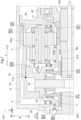
- 1 is a skeleton diagram of a vehicle drive system according to a first embodiment; Velocity diagrams of the planetary gear mechanism and output differential gear mechanism according to the first embodiment Sectional view along the axial direction of the vehicle drive device according to the second embodiment A skeleton diagram of a vehicle drive system according to a second embodiment. Partially enlarged view of a cross-sectional view along the axial direction of the vehicle drive device according to the second embodiment Partially enlarged view of a cross-sectional view along the axial direction of the vehicle drive device according to the third embodiment
- the vehicle drive device 100 includes a rotating electric machine 1 having a stator 11 and a rotor 12, a first output member 2 drivingly connected to a first wheel W1, and a second wheel W2. , a planetary gear mechanism 4 , an output differential gear mechanism 5 , and a case 9 .
- driving connection refers to a state in which two rotating elements are connected so as to be able to transmit a driving force, and the two rotating elements are connected so as to rotate integrally. It includes a state in which two rotating elements are connected so as to be able to transmit driving force via one or more transmission members.
- Such transmission members include various members that transmit rotation at the same speed or at different speeds, such as shafts, gear mechanisms, belts, and chains.
- the transmission member may include an engagement device for selectively transmitting rotation and driving force, such as a friction engagement device and a mesh type engagement device.
- the direction along the rotation axis of the rotor 12 is defined as “axial direction L".
- One side in the axial direction L is referred to as “first axial side L1”, and the other side in the axial direction L is referred to as “second axial side L2".
- a direction orthogonal to the rotation axis of the rotor 12 is defined as a "radial direction R".
- the rotation axis side of the rotor 12 is defined as “radial inner side R1", and the opposite side is defined as “radial outer side R2".
- the direction in which the rotor 12 rotates around the rotation axis is defined as “circumferential direction C”.
- the rotating electric machine 1, the first output member 2, the second output member 3, the planetary gear mechanism 4, and the output differential gear mechanism 5 are coaxially arranged.
- the output differential gear mechanism 5, the planetary gear mechanism 4, and the rotating electric machine 1 are arranged in the order described from the first axial side L1 toward the second axial side L2.
- a part of the second output member 3 is arranged so as to overlap with the rotary electric machine 1 when viewed in the radial direction R. As shown in FIG.
- overlapping in a particular direction view means that when a virtual straight line parallel to the line-of-sight direction is moved in each direction orthogonal to the virtual straight line, the virtual straight line is two It refers to the existence of at least a part of an area that intersects two elements.
- the rotating electric machine 1, the planetary gear mechanism 4, and the output differential gear mechanism 5 are housed in a case 9.
- the first output member 2 and the second output member 3 are housed in the case 9 in a state where their parts are exposed to the outside of the case 9 .
- the case 9 includes a peripheral wall portion 91, a first side wall portion 92, a second side wall portion 93, a partition wall portion 94, and a cover portion 95 in this embodiment.
- the peripheral wall portion 91 is formed in a tubular shape covering the radial outer side R2 of the rotary electric machine 1, the first output member 2, the second output member 3, the planetary gear mechanism 4, and the output differential gear mechanism 5.
- the first side wall portion 92, the second side wall portion 93, and the partition wall portion 94 are formed to extend in the radial direction R and the circumferential direction C, respectively.
- the cover portion 95 is provided so as to cover a portion of the second side wall portion 93 from the axial second side L2.
- the first side wall portion 92 is formed to cover the first axial side L1 of the output differential gear mechanism 5 .
- the second side wall portion 93 is formed so as to cover the second axial side L2 of the rotary electric machine 1 .
- the partition wall portion 94 is arranged between the rotary electric machine 1 and the planetary gear mechanism 4 in the axial direction L.
- the cover portion 95 is joined to the second side wall portion 93 from the second side L2 in the axial direction.
- the first side wall portion 92 is formed integrally with the peripheral wall portion 91 so as to block the opening of the peripheral wall portion 91 on the first axial side L1.
- the second side wall portion 93 is formed integrally with the peripheral wall portion 91 so as to block the opening of the peripheral wall portion 91 on the axial second side L2.
- the peripheral wall portion 91 is divided at a plurality of locations (here, two locations) in the axial direction L. As shown in FIG. The divided portions of the peripheral wall portion 91 are joined together and fastened by fastening members such as bolts (not shown).
- the rotating electrical machine 1 functions as a driving force source for the first wheel W1 and the second wheel W2 (see FIG. 2).
- the rotary electric machine 1 has a function as a motor (electric motor) that receives power supply and generates power, and a function as a generator (generator) that receives power supply and generates power.
- the rotary electric machine 1 is electrically connected to a power storage device (not shown) such as a battery or a capacitor. Then, the rotating electric machine 1 is powered by the electric power stored in the power storage device to generate a driving force. Further, the rotary electric machine 1 generates power by the driving force transmitted from the first wheel W1 and the second wheel W2, and charges the power storage device.
- the stator 11 of the rotating electric machine 1 has a cylindrical stator core 11a.
- Stator core 11a is fixed to non-rotating member NR.
- the stator core 11a is fixed to the peripheral wall portion 91 of the case 9 as the non-rotating member NR.
- a rotor 12 of the rotating electric machine 1 includes a cylindrical rotor core 12a.
- the rotor core 12a is rotatably supported with respect to the stator core 11a.
- the rotor 12 further includes a rotor shaft 12b coupled to rotate integrally with the rotor core 12a.
- the rotating electrical machine 1 is an inner rotor type rotating electrical machine. Therefore, the rotor core 12a is arranged radially inward R1 with respect to the stator core 11a. Further, the rotor shaft 12b is arranged radially inward R1 with respect to the rotor core 12a.
- the rotating electrical machine 1 is a rotating field type rotating electrical machine. Therefore, the stator 11 further includes a coil 11b.
- the coil 11b has a first coil end portion 11c protruding to the first axial side L1 with respect to the stator core 11a and a second coil end portion protruding to the second axial side L2 from the stator core 11a. 11d is wound around the stator core 11a.
- the rotor core 12a is provided with permanent magnets.
- the rotor shaft 12b is formed in a cylindrical shape having an axial center along the axial direction L. Further, the rotor shaft 12b is arranged so as to protrude on both sides in the axial direction L from the rotor core 12a. In the present embodiment, the portion of the rotor shaft 12b that protrudes from the rotor core 12a to the first side L1 in the axial direction is arranged to penetrate the partition wall portion 94 of the case 9 in the axial direction L. As shown in FIG. A portion of the rotor shaft 12b that protrudes from the rotor core 12a toward the first side L1 in the axial direction is rotatably supported by the partition wall 94 via a first bearing B1.
- a portion of the rotor shaft 12b that protrudes from the rotor core 12a toward the second side L2 in the axial direction is rotatably supported by the second side wall portion 93 via a second bearing B2.
- a rotation sensor 13 that detects rotation of the rotor 12 is provided integrally with the first bearing B1.
- the planetary gear mechanism 4 includes a first rotating element E1, a second rotating element E2, a third rotating element E3, and a fourth rotating element E4.
- the planetary gear mechanism 4 is configured such that the rotation speeds of the first rotation element E1, the second rotation element E2, the third rotation element E3, and the fourth rotation element E4 are in the order described.
- the “order of rotational speed” refers to the order of rotational speed in the rotating state of each rotating element.
- the rotation speed of each rotating element changes depending on the rotation state of the planetary gear mechanism, but the order of the rotation speed of each rotating element is fixed because it is determined by the structure of the planetary gear mechanism.
- the order of rotation speed of each rotating element is the same as the order of arrangement in the velocity diagram (see FIG. 3) of each rotating element.
- the “arrangement order of each rotating element in the velocity diagram” is the order in which the axes corresponding to each rotating element in the velocity diagram are arranged along the direction perpendicular to the axis.
- the arrangement direction of the shaft corresponding to each rotating element in the velocity diagram differs depending on how the velocity diagram is drawn, but the order of arrangement is fixed because it is determined by the structure of the planetary gear mechanism.
- the output differential gear mechanism 5 has an input element Ei.
- the output differential gear mechanism 5 is configured to distribute the rotation transmitted from the planetary gear mechanism 4 to the input element Ei to the first output member 2 and the second output member 3 .
- the output differential gear mechanism 5 is a planetary gear mechanism including a fifth rotating element E5, a sixth rotating element E6, and a seventh rotating element E7.
- the output differential gear mechanism 5 is configured such that the rotation speeds of the fifth rotation element E5, the sixth rotation element E6, and the seventh rotation element E7 are arranged in the described order.
- the fifth rotating element E5 is connected to the first output member 2.
- the seventh rotating element E7 is connected to the second output member 3. As shown in FIG.
- the planetary gear mechanism 4 functions as a speed reducer that reduces the speed of rotation of the rotor 12 and transmits it to the output differential gear mechanism 5 .
- the first rotating element E1 of the planetary gear mechanism 4 is connected to rotate integrally with the rotor 12 .
- a third rotating element E3 of the planetary gear mechanism 4 is connected to the case 9 .
- the fourth rotating element E4 of the planetary gear mechanism 4 is connected to the input element Ei of the output differential gear mechanism 5 so as to rotate together.
- the fourth rotating element E4 is configured integrally with the input element Ei.
- the input element Ei is the sixth rotation element E6.
- the first rotating element E1 of the planetary gear mechanism 4 is the first sun gear SG1.
- the first sun gear SG1 is supported in the radial direction R with respect to the case 9 via the first bearing B1.
- the first bearing B ⁇ b>1 corresponds to a “first support bearing” that supports the first sun gear SG ⁇ b>1 in the radial direction R with respect to the case 9 .
- the first sun gear SG1 is coupled to rotate integrally with the rotor shaft 12b. Further, as described above, in the present embodiment, the portion of the rotor shaft 12b that protrudes from the rotor core 12a toward the first side L1 in the axial direction is rotatable with respect to the partition wall portion 94 of the case 9 via the first bearing B1.
- the first bearing B1 is supported by the partition wall portion 94, and is configured to support the first sun gear SG1 in the radial direction R and the rotor 12 in the radial direction R.
- the partition wall portion 94 corresponds to a “first support wall portion” arranged between the rotary electric machine 1 and the planetary gear mechanism 4 in the axial direction L.
- the first sun gear SG1 is formed integrally with the rotor shaft 12b.
- the second rotating element E2 of the planetary gear mechanism 4 is the first carrier CR1.
- the first carrier CR1 rotatably supports a first pinion gear PG1 and a second pinion gear PG2 that rotate integrally with each other.
- the first pinion gear PG1 meshes with the first sun gear SG1 and the first ring gear RG1.
- the second pinion gear PG2 meshes with the second ring gear RG2.
- the second pinion gear PG2 has a smaller diameter than the first pinion gear PG1.
- Each of the third rotating element E3 and the fourth rotating element E4 of the planetary gear mechanism 4 is a ring gear.
- the third rotating element E3 is the first ring gear RG1.
- the fourth rotating element E4 is the second ring gear RG2.
- the sixth rotating element E6 of the output differential gear mechanism 5 is the third ring gear RG3. That is, in the present embodiment, the second ring gear RG2 as the fourth rotating element E4 of the planetary gear mechanism 4 and the third ring gear RG3 as the sixth rotating element E6 which is the input element Ei of the output differential gear mechanism 5 are connected so as to rotate integrally.
- the second ring gear RG2 and the input element Ei are connected in a state in which relative movement in the radial direction R is restricted.
- the second ring gear RG2 and the third ring gear RG3 as the input element Ei are integrally formed adjacent to each other in the axial direction L. As shown in FIG.
- the vehicle drive system 100 a rotating electric machine 1 including a rotor 12; a first output member 2 drivingly connected to the first wheel W1; a second output member 3 drivingly connected to the second wheel W2; a planetary gear mechanism 4 that slows down the rotation of the rotor 12; an output differential gear mechanism 5 having an input element Ei and distributing the rotation transmitted from the planetary gear mechanism 4 to the input element Ei to the first output member 2 and the second output member 3;
- a vehicle drive device 100 including a case 9 that houses a rotating electric machine 1, a planetary gear mechanism 4, and an output differential gear mechanism 5, A rotary electric machine 1, a first output member 2, a second output member 3, a planetary gear mechanism 4, and an output differential gear mechanism 5 are coaxially arranged,
- the planetary gear mechanism 4 includes a first rotating element E1, a second rotating element E2, a third rotating element E3, and a fourth rotating element E4.
- the first rotating element E1 is a first sun gear SG1 coupled to rotate integrally with the rotor 12
- the third rotating element E3 is the first ring gear RG1 connected to the case 9
- the fourth rotating element E4 is a second ring gear RG2 coupled to rotate integrally with the input element Ei
- the second rotating element E2 is a first carrier CR1 that rotatably supports the first pinion gear PG1 and the second pinion gear PG2 that rotate integrally with each other
- the first pinion gear PG1 meshes with the first sun gear SG1 and the first ring gear RG1,
- the second pinion gear PG2 has a smaller diameter than the first pinion gear PG1 and meshes with the second ring gear RG2,
- the first sun gear SG1 is supported in the radial direction R with respect to the case 9 via a first bearing B1 as a first support bearing,
- the second ring gear RG2 and the input element Ei are connected in
- the first rotating element E ⁇ b>1 of the planetary gear mechanism 4 is connected to the rotor 12 .
- a third rotating element E3 of the planetary gear mechanism 4 is connected to the case 9, and a fourth rotating element E4 of the planetary gear mechanism 4 is connected to the input element Ei of the differential gear mechanism 5 for output.
- each of the third rotating element E3 and the fourth rotating element E4 of the planetary gear mechanism 4 is a ring gear.
- the fourth rotating element E4 connected to the input element Ei of the output differential gear mechanism 5 is a ring gear.
- the rotating element connected to the input element Ei of the differential gear mechanism 5 for output is a sun gear or a carrier
- the dimension of the planetary gear mechanism 4 in the radial direction R can be kept small, and the planetary gear mechanism 4 can be rotated. can be arranged close to the output differential gear mechanism 5 in the axial direction L.
- the third rotating element E3 connected to the case 9 is a ring gear.
- the first sun gear SG1 as the first rotating element E1 of the planetary gear mechanism 4 is supported in the radial direction R with respect to the case 9 via the first bearing B1 as the first support bearing. ing. Then, the second ring gear RG2 as the fourth rotating element E4 of the planetary gear mechanism 4 and the input element Ei of the output differential gear mechanism 5 are connected in a state in which relative movement in the radial direction R is restricted.
- the input element Ei of the output differential gear mechanism 5 can be supported in the radial direction R by utilizing the aligning action (self-aligning action) of the planetary gear mechanism 4 .
- the aligning action self-aligning action
- a large reduction ratio of the planetary gear mechanism 4 can be ensured and the differential gear for output can be increased. It is easy to reduce the size of the vehicle drive device 100 while appropriately supporting the mechanism 5 .
- the case 9 includes the partition wall portion 94 as the first support wall portion disposed between the rotating electric machine 1 and the planetary gear mechanism 4 in the axial direction L,
- the first bearing B1 as a first support bearing is supported by the partition wall portion 94 and configured to support the first sun gear SG1 in the radial direction R and the rotor 12 in the radial direction R.
- the axial direction of the vehicle drive device 100 is reduced. It is easy to keep the dimension of L small.
- the output differential gear mechanism 5 includes the fifth rotary element E5, the sixth rotary element E6, and the seventh rotary element E7.
- a planetary gear mechanism configured so that the order of the rotation speeds of E6 and the seventh rotation element E7 is the order of description,
- the fifth rotating element E5 is connected to the first output member 2
- the seventh rotating element E7 is connected to the second output member 3
- the sixth rotating element E6 is the third ring gear RG3 and the input element Ei.
- the fifth rotating element E5 and the seventh rotating element E7 of the output differential gear mechanism 5 are connected to the first output member 2 and the second output member 3, respectively.
- the output differential gear mechanism 5 can be a planetary gear type differential gear mechanism. Therefore, compared to a configuration in which the output differential gear mechanism 5 is a bevel gear type differential gear mechanism, it is easier to keep the dimension of the vehicle drive device 100 in the axial direction L small.
- the third rotation element E3 and the fourth rotation element E4 of the planetary gear mechanism 4 are the first ring gear RG1 and the second ring gear RG2, respectively, and the sixth rotation of the output differential gear mechanism 5.
- Element E6 is the third ring gear RG3.
- the first ring gear RG1 or the second ring gear RG2 is connected to rotate integrally with the third ring gear RG3.
- the connection between the fourth rotating element E4 and the sixth rotating element E6 can be performed in the radially outer region R2 with respect to the planetary gear mechanism 4 and the output differential gear mechanism 5.
- the output differential gear mechanism 5 is a planetary gear mechanism including a second sun gear SG2, a second carrier CR2, and a third ring gear RG3.
- the second sun gear SG2 is connected to rotate integrally with the first output member 2
- the second carrier CR2 is coupled to rotate integrally with the second output member 3
- the third ring gear RG3 is the input element Ei.
- the second output member 3 connected to the second carrier CR2 is moved in the radial direction R by utilizing the aligning action (self-aligning action) of the output differential gear mechanism 5, which is a planetary gear mechanism.
- the output differential gear mechanism 5 which is a planetary gear mechanism.
- the output differential gear mechanism 5 is a double pinion type planetary gear mechanism.
- the fifth rotating element E5 of the output differential gear mechanism 5 is the second sun gear SG2.
- the seventh rotating element E7 of the output differential gear mechanism 5 is the second carrier CR2.
- the sixth rotating element E6 of the output differential gear mechanism 5 is the third ring gear RG3.
- the second carrier CR2 rotatably supports a third pinion gear PG3 and a fourth pinion gear PG4 that mesh with each other.
- the third pinion gear PG3 meshes with the second sun gear SG2 and the fourth pinion gear PG4.
- the fourth pinion gear PG4 meshes with the third ring gear RG3 and the third pinion gear PG3.
- the output differential gear mechanism 5 is a double pinion type planetary gear mechanism
- the fifth rotating element E5 is the second sun gear SG2
- the seventh rotating element E7 is the second carrier CR2.
- the torque transmitted from the planetary gear mechanism 4 to the sixth rotating element E6 is transferred to the first output member 2, as compared with the configuration in which the output differential gear mechanism 5 is a single pinion type planetary gear mechanism. It is easy to adopt a configuration in which the power can be transmitted to the fifth rotating element E5 connected to the second output member 3 and the seventh rotating element E7 connected to the second output member 3 at an equal ratio.
- the vehicle drive system 100 further includes a parking gear 6 and a parking lock mechanism 7 that selectively engages with the parking gear 6 .
- the parking gear 6 is provided on a rotating member that interlocks with the first wheel W1 and the second wheel W2 (see FIG. 2).
- the parking gear 6 is formed on the tubular member 10 .
- the tubular member 10 is formed in a tubular shape having an axis along the axial direction L.
- the tubular member 10 is also formed with a second ring gear RG2 and a third ring gear RG3. Therefore, in the present embodiment, the parking gear 6 is arranged so as to overlap the output differential gear mechanism 5 when viewed in the radial direction R.
- the parking gear 6 is coupled to rotate integrally with the third ring gear RG3 as the input element Ei of the output differential gear mechanism 5 .
- the parking gear 6, the third ring gear RG3, and the second ring gear RG2 are arranged in the stated order from the first axial side L1 toward the second axial side L2.
- the parking gear 6, the third ring gear RG3, and the second ring gear RG2 are integrally formed with one cylindrical member 10 by cutting or the like.
- the first ring gear RG1 is connected to the case 9 in this embodiment.
- the first ring gear RG1 is connected to the peripheral wall portion 91 of the case 9 . More specifically, the spline engagement portion formed on the outer peripheral surface of the first ring gear RG1 and the spline engagement portion formed on the inner peripheral surface of the peripheral wall portion 91 are engaged with each other, whereby the first ring gear RG1 are connected to the case 9 so as not to rotate.
- the vehicle drive device 100 further includes the parking gear 6 and the parking lock mechanism 7 selectively engaged with the parking gear 6,
- the first ring gear RG1 is connected to the case 9,
- the second ring gear RG ⁇ b>2 , the third ring gear RG ⁇ b>3 and the parking gear 6 are formed on the same cylindrical member 10 .
- the second ring gear RG2, the third ring gear RG3, and the parking gear 6 are integrally formed.
- the second ring gear RG2, the third ring gear RG3, and the parking gear 6 are formed as separate members, it is easier to reduce the size of the vehicle drive device 100 in the axial direction L and the radial direction R. .
- the parking gear 6 is arranged so as to overlap the output differential gear mechanism 5 when viewed in the radial direction R, and is coupled to rotate integrally with the input element Ei.
- the dimension of the vehicle drive device 100 in the axial direction L can be reduced compared to the configuration in which the parking gear 6 is arranged on one side of the output differential gear mechanism 5 in the axial direction L. can.
- the cylindrical member 10 is connected to the support member 20 extending along the radial direction R so as to rotate integrally.
- the support member 20 is formed to extend radially inward R1 from the tubular member 10 .
- the support member 20 is arranged on the first side L1 in the axial direction with respect to the output differential gear mechanism 5 .
- the support member 20 is rotatably supported by the first side wall portion 92 of the case 9 via the third bearing B3.
- the first output member 2 is connected to rotate integrally with the second sun gear SG2.
- the first output member 2 is formed integrally with the second sun gear SG2.
- the first output member 2 is arranged so as to pass through the support member 20 and the first side wall portion 92 of the case 9 in the axial direction L.
- the first output member 2 is connected to rotate integrally with a first drive shaft DS1 drivingly connected to the first wheel W1.
- the first output member 2 is formed in a tubular shape having an axial center along the axial direction L. As shown in FIG.
- the first drive shaft DS1 is inserted into the first output member 2 from the first axial side L1 so that the first drive shaft DS1 is positioned radially inward R1 with respect to the first output member 2. , they are connected to each other by spline engagement.
- the second output member 3 includes a connecting member 31 that is connected to rotate integrally with the second drive shaft DS2 that is drivingly connected to the second wheel W2, and the connecting member 31 and the seventh rotation shaft. an output shaft 32 extending along the axial direction L so as to connect with the element E7.
- the connecting member 31 is arranged so as to pass through the second side wall portion 93 and the cover portion 95 of the case 9 in the axial direction L.
- the connecting member 31 is rotatably supported with respect to the second side wall portion 93 via the fourth bearing B4, and is rotatably supported with respect to the cover portion 95 via the fifth bearing B5.
- the second output member 3 is formed in a tubular shape having an axial center along the axial direction L.
- the second drive shaft DS2 is inserted into the second output member 3 from the axial second side L2 so that the second drive shaft DS2 is positioned radially inward R1 with respect to the second output member 3. , they are connected to each other by spline engagement.
- the output shaft 32 passes through the planetary gear mechanism 4 in the axial direction L on the radially inner side R1 with respect to the planetary gear mechanism 4, and rotates around the rotor core 12a on the radially inner side R1 with respect to the rotor shaft 12b. It is arranged so as to penetrate in the direction L.
- the output shaft 32 is connected to the second carrier CR2 and the connecting member 31 so as to rotate together.
- the output shaft 32 is integrally formed with the second carrier CR2.
- a first oil passage 81 is formed inside the output shaft 32 .
- the first oil passage 81 includes an axial oil passage 81a, a first radial oil passage 81b, a second radial oil passage 81c, and a third radial oil passage 81d.
- the axial oil passage 81 a is formed to extend along the axial direction L inside the output shaft 32 .
- the first radial oil passage 81b, the second radial oil passage 81c, and the third radial oil passage 81d extend along the radial direction R so that the axial oil passage 81a and the outer peripheral surface of the output shaft 32 communicate with each other. It is formed so as to extend
- the first radial oil passage 81b is arranged so as to overlap the second output member 3 when viewed in the radial direction R.
- the plurality of first radial oil passages 81b are arranged in the circumferential direction C at intervals.
- the second radial oil passage 81c is arranged so as to overlap the rotor shaft 12b and not the second output member 3 when viewed in the radial direction R.
- the plurality of second radial oil passages 81c are arranged at intervals in the axial direction L and the circumferential direction C. As shown in FIG.
- the third radial oil passage 81d is arranged so as to overlap the revolution locus of the second pinion gear PG2 of the planetary gear mechanism 4 when viewed in the radial direction R.
- the plurality of third radial oil passages 81d are arranged at intervals in the axial direction L and the circumferential direction C. As shown in FIG.
- the second oil passage 82 is formed in the second side wall portion 93 of the case 9 .
- the second oil passage 82 is formed to extend along the radial direction R. As shown in FIG. In the example shown in FIG. 1, the second oil passage 82 is formed so as to pass between the second bearing B2 and the fourth bearing B4 in the axial direction L.
- the second side wall portion 93 includes a thick wall portion 93a having a relatively large thickness (dimension in the axial direction L) and a thin wall portion 93b having a relatively small thickness.
- a partial region in the circumferential direction C of the second side wall portion 93 is the thin wall portion 93b, and the remaining region is the thick wall portion 93a.
- a second oil passage 82 is formed in the thick wall portion 93a.
- the connecting member 31 is formed with a third oil passage 83 .
- the third oil passage 83 is formed across the inner peripheral surface and the outer peripheral surface of the connecting member 31 so as to allow the first radial oil passage 81b and the second oil passage 82 to communicate with each other.
- oil discharged from a hydraulic pump (not shown) provided in the vehicle drive system 100 is supplied to the second oil passage 82 .
- the oil supplied to the second oil passage 82 is supplied to the axial oil passage 81a through the third oil passage 83 and the first radial oil passage 81b.
- the oil supplied to the axial oil passage 81a is supplied to the inner peripheral surface of the rotor shaft 12b through the second radial oil passage 81c.
- the oil supplied to the axial oil passage 81a is supplied to the second pinion gear PG2 of the planetary gear mechanism 4 and the like through the third radial oil passage 81d.
- the oil supplied to the axial direction oil passage 81a passes through the fourth oil passage 84 formed in the second carrier CR2 of the output differential gear mechanism 5, to the third pinion gear PG3, the fourth pinion gear PG4, etc. supplied.
- the second oil passage 82 is arranged on the side opposite to the planetary gear mechanism 4 and the output differential gear mechanism 5 in the axial direction L with respect to the stator 11 of the rotary electric machine 1 . That is, the planetary gear mechanism 4 and the output differential gear mechanism 5 are arranged on the first side L1 in the axial direction with respect to the stator 11 .
- the second oil passage 82 is arranged on the axial second side L ⁇ b>2 with respect to the stator 11 . In the example shown in FIG. 1 , the second oil passage 82 is arranged on the axial second side L2 of the second coil end portion 11 d of the stator 11 .
- the rotating electrical machine 1 further includes a terminal portion 14 for connecting the coil 11b of the stator 11 to a power source (not shown).
- the terminal portion 14 is arranged to protrude from the stator 11 toward the axial second side L2.
- the terminal portion 14 is formed such that a portion of the second coil end portion 11d in the circumferential direction C protrudes toward the second axial side L2.
- the terminal section 14 includes a three-phase terminal electrically connected to the three-phase output terminal of the inverter.
- the arrangement area of the terminal portion 14 in the circumferential direction C does not overlap the arrangement area of the second oil passage 82 in the circumferential direction C.
- the arrangement area in the axial direction L of the terminal portion 14 overlaps the arrangement area in the axial direction L of the second oil passage 82 .
- the terminal portion 14 is arranged so as not to overlap the thick wall portion 93a of the second side wall portion 93 but to overlap the thin wall portion 93b of the second side wall portion 93 when viewed in the axial direction along the axial direction L. It is The terminal portion 14 is arranged so as to overlap the thick wall portion 93a in which the second oil passage 82 is formed when viewed in the radial direction R. As shown in FIG.
- the rotating electric machine 1 includes the stator 11 including the coil 11b, and the terminal portion 14 for connecting the coil 11b to the power source.
- the planetary gear mechanism 4 and the output differential gear mechanism 5 are arranged on the first side L1 in the axial direction with respect to the stator 11,
- the terminal portion 14 is arranged to protrude from the stator 11 toward the second side L2 in the axial direction,
- a second oil passage 82 extending along the radial direction R is arranged on the second axial side L2 with respect to the stator 11,
- the arrangement area of the second oil passage 82 in the circumferential direction C and the arrangement area of the terminal portion 14 in the circumferential direction C do not overlap,
- the arrangement area of the second oil passage 82 in the axial direction L and the arrangement area of the terminal portion 14 in the axial direction L overlap.
- the dimension of the vehicle drive device 100 in the axial direction L can be reduced.
- FIG. 3 shows a velocity diagram of the planetary gear mechanism 4 and the output differential gear mechanism 5 according to this embodiment.
- the vertical lines correspond to the rotation speed of each rotating element of the planetary gear mechanism 4 and the output differential gear mechanism 5 .
- Each of the plurality of vertical lines arranged in parallel corresponds to each rotating element of the planetary gear mechanism 4 and the differential gear mechanism 5 for output.
- the symbols shown above the plurality of vertical lines are the symbols of the corresponding rotating elements.
- the reference numerals shown below the multiple vertical lines are the reference numerals of the elements rotating integrally with the rotating elements corresponding to the upper reference numerals. Also, in the velocity diagram of FIG.
- black circles on a plurality of vertical lines indicate that rotating elements corresponding to the target vertical lines rotate integrally.
- crosses on vertical lines indicate that the rotating element corresponding to the target vertical line is fixed to the case 9 as the non-rotating member NR.
- the rotation transmitted from the rotor 12 of the rotary electric machine 1 to the first sun gear SG1 is reversed and decelerated in the planetary gear mechanism 4, and transmitted to the second ring gear RG2. .
- the torque of the rotary electric machine 1 is amplified and transmitted to the second ring gear RG2.
- the rotation and torque transmitted from the second ring gear RG2 to the third ring gear RG3 are connected to the first output member 2 connected to the second sun gear SG2 and the second carrier CR2 by the output differential gear mechanism 5. is distributed to the second output member 3 and the second output member 3.
- FIG. 1 a vehicle drive system 100 according to a second embodiment will be described with reference to FIGS. 4 to 6.
- FIG. the configuration of the case 9 and the configuration of the output differential gear mechanism 5 are different from those of the first embodiment. Differences from the first embodiment will be mainly described below. Note that points that are not particularly described are the same as those in the first embodiment.
- the case 9 does not have a cover portion 95 in this embodiment. Therefore, in this embodiment, the fifth bearing B5 that supports the second output member 3 with respect to the cover portion 95 is not provided.
- the output differential gear mechanism 5 includes a differential case 51, a shaft member 52, a pinion gear 53, and a pair of side gears 54.
- the differential case 51 is formed to accommodate a pinion gear 53 and a pair of side gears 54 .
- the differential case 51 is connected to rotate integrally with the fourth rotating element E4 of the planetary gear mechanism 4 . That is, in this embodiment, the differential case 51 is the input element Ei.
- the shaft member 52 is arranged so as to extend along the radial direction R.
- the shaft member 52 is supported by the differential case 51 so as to rotate together with the differential case 51 .
- a plurality of shaft members 52 are distributed in the circumferential direction C along the radial direction R (for example, when viewed in the axial direction L, the four shaft members 52 are arranged in a cross shape). configured).
- the pinion gear 53 is rotatably supported by the shaft member 52 .
- the pinion gear 53 is configured to rotate (rotate) around the shaft member 52 and rotate (revolve) around the rotation axis of the differential case 51 (see one-dot chain line in FIG. 6).
- a pinion gear 53 is attached to each of the plurality of shaft members 52 distributed in the circumferential direction C. As shown in FIG. Note that the pinion gear 53 corresponds to a "first bevel gear".
- the pair of side gears 54 are arranged on both sides of the shaft member 52 in the axial direction L.
- a pair of side gears 54 mesh with the pinion gear 53 .
- the side gear 54 corresponds to a "second bevel gear”.
- first side gear 541 the side gear 54 on the first side L1 in the axial direction
- second side gear 542 the side gear 54 on the second side L2 in the axial direction
- the first side gear 541 is connected via the first output member 2 so as to rotate integrally with the first drive shaft DS1 drivingly connected to the first wheel W1.
- the first output member 2 is arranged to extend from the first side gear 541 to the axial first side L1.
- the first output member 2 is rotatably supported relative to the differential case 51 via an eighth bearing B8.
- the eighth bearing B8 is a slide bearing.
- the first output member 2 is formed in a tubular shape having an axial center along the axial direction L. As shown in FIG. A first drive shaft DS1 is inserted radially inward R1 from the first output member 2 from the first side L1 in the axial direction, and they are connected to each other by spline engagement.
- the second side gear 542 is integrated with the second drive shaft DS2 drivingly connected to the second wheel W2 via the output shaft 32 and the connecting member 31. connected for rotation.
- the output shaft 32 is inserted from the axial second side L2 inside the second side gear 542 in the radial direction R, and they are connected to each other by spline engagement.
- the connecting member 31 and the output shaft 32 are integrally formed.
- the output differential gear mechanism 5 includes the differential case 51 and the shaft member supported by the differential case 51 and extending along the radial direction R. 52, a pinion gear 53 housed in a differential case 51 and rotatably supported by a shaft member 52, and a pair of gears housed in the differential case 51 and engaged with the pinion gear 53 on both sides of the shaft member 52 in the axial direction L. and a side gear 54 of A differential case 51 is the input element Ei.
- the output differential gear mechanism 5 can be a bevel gear type differential gear mechanism. Since the differential case 51 housing the pinion gear 53 and the side gear 54 is the input element Ei connected to the fourth rotating element E4, the freedom of the connection structure between the planetary gear mechanism 4 and the output differential gear mechanism 5 It is easy to secure a high degree.
- the differential case 51 includes a first member 511 and a second member 512 in this embodiment.
- the first member 511 and the second member 512 are configured to be joined in the axial direction L to each other.
- the first member 511 is arranged on the first side L1 in the axial direction with respect to the shaft member 52
- the second member 512 is arranged on the second side L2 in the axial direction with respect to the shaft member 52.
- the first member 511 and the second member 512 support the shaft member 52 so as to sandwich the shaft member 52 in the axial direction L.
- the cylindrical member 10 is not provided in this embodiment. 4, the parking gear 6, the first member 511, and the second member 512 are fastened together in the axial direction L by bolts 50.
- the parking gear 6 in a state where the parking gear 6 is in contact with the first member 511 from the axial direction first side L1, the parking gear 6 is located in a region in the circumferential direction C of the differential case 51 where the shaft member 52 does not exist. , the first member 511, and the second member 512 from the axial direction first side L1.
- the vehicle drive device 100 further includes the parking gear 6 and the parking lock mechanism 7 selectively engaged with the parking gear 6,
- the differential case 51 includes a first member 511 and a second member 512 that are joined together in the axial direction L, The parking gear 6 , the first member 511 and the second member 512 are fastened together in the axial direction L by bolts 50 .
- the differential case 51 includes a first member 511 and a second member 512 that are joined together in the axial direction L. As shown in FIG. Accordingly, the work of assembling the shaft member 52, the pinion gear 53, and the side gear 54 to the differential case 51 can be easily performed. Moreover, according to this configuration, the parking gear 6 , the first member 511 and the second member 512 are fastened together in the axial direction L by the bolt 50 . As a result, compared to a configuration in which separate connecting members are used to connect the parking gear 6 to the differential case 51 and to connect the first member 511 and the second member 512, the vehicle drive device 100 is The number of parts can be reduced.
- the differential case 51 as the input element Ei of the output differential gear mechanism 5 is connected to the first side wall portion 92 of the case 9 via the third bearing B3. It is rotatably supported.
- the third bearing B3 includes a radial bearing B31 and a thrust bearing B32.
- the first side wall portion 92 corresponds to a "second support wall portion" arranged on the first side L1 in the axial direction from the differential gear mechanism 5 for output.
- the radial bearing B31 is arranged between the first member 511 and the first side wall portion 92 in the radial direction R.
- the radial bearing B31 supports the first member 511 in the radial direction R.
- the radial bearing B31 is arranged on the first side L1 in the axial direction with respect to the plurality of gears (here, the plurality of pinion gears 53 and the pair of side gears 54) forming the output differential gear mechanism 5.
- the radial bearing B31 is a slide bearing or a needle roller bearing.
- the radial bearing B31 is a sliding bearing.
- the radial bearing B31 is arranged on the first side L1 in the axial direction with respect to the plurality of gears constituting the output differential gear mechanism 5, and is a "second support bearing" that rotatably supports the input element Ei. corresponds to
- the thrust bearing B32 is arranged between the first member 511 and the first side wall portion 92 in the axial direction L.
- the thrust bearing B32 supports the first member 511 in the axial direction L.
- the thrust bearing B32 is arranged on the first side L1 in the axial direction with respect to the plurality of gears (here, the plurality of pinion gears 53 and the pair of side gears 54) that constitute the output differential gear mechanism 5.
- the thrust bearing B32 is arranged on the second axial side L2 and radially outward R2 with respect to the radial bearing B31.
- the thrust bearing B32 is a needle roller bearing.
- the differential case 51 is rotatably supported by the partition wall portion 94 of the case 9 via the sixth bearing B6 and the seventh bearing B7.
- the sixth bearing B6 is arranged between the second member 512 and a portion of the first carrier CR1 located on the axial first side L1 with respect to the second pinion gear PG2 in the axial direction L.
- the seventh bearing B7 is arranged between a portion of the first carrier CR1 located on the second side L2 in the axial direction with respect to the first pinion gear PG1 and the partition wall portion 94 in the axial direction L.
- the second member 512 is supported in the axial direction L with respect to the partition wall portion 94 via the sixth bearing B6 and the seventh bearing B7.
- each of the sixth bearing B6 and the seventh bearing B7 is a needle roller bearing.
- the differential case 51 is supported in the radial direction R by the radial bearing B31, and is supported in the axial direction L by the thrust bearing B32, the sixth bearing B6, and the seventh bearing B7. . That is, in the present embodiment, the bearing that supports the output differential gear mechanism 5 in the radial direction R is only the radial bearing B31.
- the planetary gear mechanism 4 is arranged on the first side L1 in the axial direction with respect to the rotor 12,
- the output differential gear mechanism 5 is arranged on the first side L1 in the axial direction with respect to the planetary gear mechanism 4,
- the input element Ei of the output differential gear mechanism 5 is connected via a radial bearing B31 as a second support bearing arranged on the first side L1 in the axial direction with respect to the plurality of gears forming the output differential gear mechanism 5. and is supported in the radial direction R with respect to the case 9 .
- the input gear of the output differential gear mechanism 5 is provided by the radial bearing B31 as the second support bearing.
- Element Ei can be supported in radial direction R.
- the aligning action (self-aligning action) of the planetary gear mechanism 4 is used to The input element Ei of the output differential gear mechanism 5 can be supported in the radial direction R.
- the input element Ei of the output differential gear mechanism 5 is shifted in the radial direction R only by the radial bearing B31 arranged on the first side L1 in the axial direction with respect to the gears constituting the output differential gear mechanism 5. It is possible to realize a configuration supported by Therefore, compared to a configuration in which the input element Ei is supported in the radial direction R by a plurality of bearings arranged on both sides in the axial direction L with respect to the plurality of gears constituting the output differential gear mechanism 5, the vehicle drive mechanism 5 It is easy to reduce the size and cost of the device 100 .
- the case 9 includes a first side wall portion 92 as a second support wall portion arranged on the first side L1 in the axial direction from the output differential gear mechanism 5,
- the input element Ei is supported in the radial direction R by a slide bearing or needle roller bearing disposed between the input element Ei and the first side wall portion 92 in the radial direction R. It is supported in the axial direction L by a thrust bearing B32 arranged between the side wall portion 92 and the axial direction L.
- the size of the vehicle drive device 100 is suppressed while supporting the input element Ei. A large degree of rigidity can be ensured.
- the differential case 51 as the input element Ei of the output differential gear mechanism 5 has a connecting portion 513 .
- the connecting portion 513 is formed to protrude from the second member 512 toward the radially outer side R2.
- the connecting portion 513 is configured integrally with the second ring gear RG2.
- integrally constructed includes that a plurality of elements are constructed of the same member and that a plurality of elements are inseparably connected by welding or the like.
- connected so as to rotate integrally includes that a plurality of elements are separably connected such as by spline engagement.
- the differential case 51 as the input element Ei of the output differential gear mechanism 5 has a fitting outer peripheral surface 51a facing radially outward R2.
- the second ring gear RG2 has a fitting inner peripheral surface 4a facing radially inward R1.
- the fitting inner peripheral surface 4a and the fitting outer peripheral surface 51a are fitted to each other so as to be in contact with each other in the radial direction R.
- a fitting outer peripheral surface 51 a is formed on the outer peripheral surface of the connecting portion 513 of the differential case 51 .
- a fitting inner peripheral surface 4a is formed on the inner peripheral surface of a portion of the second ring gear RG2 that protrudes from the toothed portion toward the first side L1 in the axial direction.
- the second ring gear RG2 and the input element Ei are fixed to each other by welding while the fitting inner peripheral surface 4a and the fitting outer peripheral surface 51a are fitted to each other.
- the coupling portion 513 of the differential case 51 is fitted to the second ring gear RG2 from the first side L1 in the axial direction, and the coupling portion 513 and the second ring gear RG2 are connected to each other in the axial direction. It is welded from one side L1.
- the second ring gear RG2 has the fitting inner peripheral surface 4a facing the radially inner side R1
- the input element Ei has a fitting outer peripheral surface 51a facing the radially outer side R2
- the second ring gear RG2 and the input element Ei are fixed to each other by welding in a state in which the fitting inner peripheral surface 4a and the fitting outer peripheral surface 51a are in contact with each other in the radial direction R. As shown in FIG.
- the first pinion gear PG1 and the second pinion gear PG2 are helical gears.
- the direction of the thrust load received by the first pinion gear PG1 from the first sun gear SG1 and the direction of the thrust load received by the second pinion gear PG2 from the second ring gear RG2 are the same as the direction of the thrust load received by the first pinion gear PG1 from the first ring gear RG1.
- the sum of the magnitude of the thrust load that the first pinion gear PG1 receives from the first sun gear SG1 and the magnitude of the thrust load that the second pinion gear PG2 receives from the second ring gear RG2 is
- the helical directions of the first pinion gear PG1 and the second pinion gear PG2 are set so as to be equal to or close to the magnitude of the thrust load received from RG1.
- the resultant force of the thrust loads from the first sun gear SG1, the first ring gear RG1, and the second ring gear RG2 acting on the first pinion gear PG1 and the second pinion gear PG2 that rotate integrally with each other is zero or a value close to zero.
- the helical directions of the first pinion gear PG1 and the second pinion gear PG2 are set so that
- the "helical direction" of each pinion gear refers to the direction of the torsion angle (twisting direction) of the teeth of each pinion gear.
- the black arrow shown on the first pinion gear PG1 adjacent to the first sun gear SG1 indicates the direction of the thrust load that the first pinion gear PG1 receives from the first sun gear SG1.
- a black arrow shown on the first pinion gear PG1 adjacent to the first ring gear RG1 indicates the direction of the thrust load that the first pinion gear PG1 receives from the first ring gear RG1.
- a black arrow shown on the second pinion gear PG2 adjacent to the second ring gear RG2 indicates the direction of the thrust load that the second pinion gear PG2 receives from the second ring gear RG2.
- the thrust load that the first pinion gear PG1 receives from the first sun gear SG1, the thrust load that the second pinion gear PG2 receives from the second ring gear RG2, and the thrust load that the first pinion gear PG1 receives from the first ring gear RG1. can cancel each other out.
- This prevents an excessive thrust load from acting on the bearings (here, the sixth bearing B6 and the seventh bearing B7) that support the first carrier CR1 that rotatably supports the first pinion gear PG1 and the second pinion gear PG2. can be avoided.
- the eighth bearing B8 is not provided in this embodiment. That is, in this embodiment, the differential case 51 is not supported by the first output member 2, but is supported by the first side wall portion 92 of the case 9 via the radial bearing B31.
- the radial bearing B31 is a needle roller bearing. A gap is formed between the first member 511 of the differential case 51 and the first output member 2 in the radial direction R.
- the differential case 51 has a differential case subject portion 514 .
- the differential case target portion 514 corresponds to "a portion on the second side L2 in the axial direction with respect to the central position in the axial direction L of the output differential gear mechanism 5 in the differential case 51".
- the "center position in the axial direction L of the output differential gear mechanism 5" is the position of the axial center of the shaft member 52 in the axial direction L.
- the differential case target portion 514 is formed to protrude from the second member 512 of the differential case 51 toward the axial second side L2. Further, the differential case target portion 514 is rotatably supported relative to the second output member 3 via the ninth bearing B9.
- the second output member 3 is arranged so as to penetrate the differential case target portion 514 in the axial direction L on the radial inner side R1.
- a ninth bearing B ⁇ b>9 is arranged between the inner peripheral surface of the differential case target portion 514 and the outer peripheral surface of the second output member 3 .
- the output shaft 32 of the second output member 3 is arranged so as to pass through the differential case target portion 514 in the axial direction L on the radial inner side R1.
- a ninth bearing B ⁇ b>9 is arranged between the inner peripheral surface of the differential case target portion 514 and the outer peripheral surface of the output shaft 32 .
- the ninth bearing B9 corresponds to a "third support bearing".
- the ninth bearing B9 may not be provided.
- the first output member 2 is arranged on the first side L1 in the axial direction with respect to the second output member 3, A portion on the second side L2 in the axial direction with respect to the central position in the axial direction L of the output differential gear mechanism 5 in the differential case 51 is defined as a differential case target portion 514,
- the second output member 3 is arranged so as to penetrate the differential case target portion 514 in the radial direction inner side R1 in the axial direction L,
- a ninth bearing B ⁇ b>9 as a third support bearing is arranged between the inner peripheral surface of the differential case target portion 514 and the outer peripheral surface of the second output member 3 .
- the differential case target portion 514 which is the portion on the second side L2 in the axial direction with respect to the central position in the axial direction L of the output differential gear mechanism 5 in the differential case 51, is the ninth bearing B9. Supported by Thereby, the support accuracy of the differential case 51 can be improved.
- the parking gear 6 is arranged so as to overlap the output differential gear mechanism 5 when viewed in the radial direction R, as an example.
- the parking gear 6 may be arranged on one side in the axial direction L of the output differential gear mechanism 5 .
- the configuration in which the second ring gear RG2, the third ring gear RG3, and the parking gear 6 are formed on the same tubular member 10 has been described as an example. However, without being limited to such a configuration, they may be configured by being divided into a plurality of members.
- the second ring gear RG2, the third ring gear RG3, and the parking gear 6 may be formed as separate members and connected to rotate integrally with each other.
- the arrangement area of the second oil passage 82 in the circumferential direction C and the arrangement area of the terminal portion 14 in the circumferential direction C do not overlap, and the axial direction of the second oil passage 82 A configuration in which the arrangement area in L overlaps with the arrangement area in the axial direction L of the terminal portion 14 has been described as an example.
- the second oil passage 82 and the terminal portion 14 may be displaced from each other in the axial direction L without being limited to such a configuration.
- the differential case 51 is rotatably supported relative to the first output member 2 via the eighth bearing B8, and the case 9 is supported via the radial bearing B31.
- the configuration has been described as an example in which it is rotatably supported with respect to.
- the first output member 2 is rotatably supported with respect to the case 9 via the radial bearing B31
- the differential case 51 is supported via the eighth bearing B8.
- a configuration in which the differential case 51 is supported so as to be relatively rotatable with respect to the first output member 2 that is, a configuration in which the differential case 51 is indirectly supported by the case 9 via the first output member 2 may be used.
- the differential case 51 of the output differential gear mechanism 5 includes the first member 511 and the second member 512 joined together in the axial direction L, and the parking gear 6, the first member 511, and the second member 512 are fastened together in the axial direction L by the bolt 50, as an example.
- the connection of the parking gear 6 to the differential case 51 and the connection of the first member 511 and the second member 512 are performed using separate connection members. It's okay to be.
- the differential case 51 may be configured by one member without the first member 511 and the second member 512 .
- the input element Ei is radially moved by the radial bearing B31, which is a sliding bearing, disposed between the input element Ei and the first side wall portion 92 in the radial direction R.
- the radial bearing B31 which is a sliding bearing
- a configuration in which the input element Ei and the first side wall portion 92 are supported in the axial direction L by the thrust bearing B32 arranged between the input element Ei and the first side wall portion 92 in the axial direction L has been described as an example.
- the input element Ei may be supported in both the radial direction R and the axial direction L by ball bearings, for example.
- the vehicle drive device (100) includes: a rotating electric machine (1) having a rotor (12); a first output member (2) drivingly connected to the first wheel (W1); a second output member (3) drivingly connected to the second wheel (W2); a planetary gear mechanism (4) that slows down the rotation of the rotor (12); An output that comprises an input element (Ei) and distributes rotation transmitted from the planetary gear mechanism (4) to the input element (Ei) to the first output member (2) and the second output member (3) a differential gear mechanism (5) for A vehicle drive device (100) comprising a case (9) housing the rotating electric machine (1), the planetary gear mechanism (4), and the output differential gear mechanism (5), The rotating electrical machine (1), the first output member (2), the second output member (3), the planetary gear mechanism (4), and the output differential gear mechanism (5) are arranged coaxially.
- the planetary gear mechanism (4) comprises a first rotating element (E1), a second rotating element (E2), a third rotating element (E3), and a fourth rotating element (E4), and the first rotating element ( E1), the second rotating element (E2), the third rotating element (E3), and the fourth rotating element (E4) are configured so that their rotation speeds are in the order described,
- the first rotating element (E1) is a first sun gear (SG1) coupled to rotate integrally with the rotor (12)
- the third rotating element (E3) is a first ring gear (RG1) connected to the case (9)
- the fourth rotating element (E4) is a second ring gear (RG2) coupled to rotate integrally with the input element (Ei)
- the second rotating element (E2) is a first carrier (CR1) that rotatably supports a first pinion gear (PG1) and a second pinion gear (PG2) that rotate integrally with each other,
- the first pinion gear (PG1) meshes with the first sun gear (SG1) and the first ring
- the first rotating element (E1) of the planetary gear mechanism (4) is connected to the rotor (12).
- the third rotating element (E3) of the planetary gear mechanism (4) is connected to the case (9), and the fourth rotating element (E4) of the planetary gear mechanism (4) is connected to the output differential gear mechanism (5). It is linked to the input elements (Ei).
- each of the third rotating element (E3) and the fourth rotating element (E4) of the planetary gear mechanism (4) is a ring gear.
- the fourth rotating element (E4) connected to the input element (Ei) of the output differential gear mechanism (5) is a ring gear. This reduces the radial dimension (R) of the planetary gear mechanism (4) compared to a configuration in which the rotating element connected to the input element (Ei) of the output differential gear mechanism (5) is a sun gear or a carrier. It is easy to dispose the planetary gear mechanism (4) close to the output differential gear mechanism (5) in the axial direction (L) while keeping the size small.
- the third rotating element (E3) connected to the case (9) is a ring gear.
- the first sun gear (SG1) as the first rotating element (E1) of the planetary gear mechanism (4) is diametrically opposed to the case (9) via the first support bearing (B1). It is supported in direction (R).
- the second ring gear (RG2) as the fourth rotating element (E4) of the planetary gear mechanism (4) and the input element (Ei) of the output differential gear mechanism (5) are arranged in the radial direction (R).
- the input element (Ei) of the output differential gear mechanism (5) can be supported in the radial direction (R) by utilizing the aligning action (self-aligning action) of the planetary gear mechanism (4). can.
- the output differential gear mechanism ( 5) can be properly supported. Therefore, it is easy to reduce the size and cost of the vehicle drive device (100).
- the direction along the rotation axis of the rotor (12) is defined as the axial direction (L)
- one side of the axial direction (L) is defined as the axial direction first side (L1)
- the axial direction (L) With the other side as the axial second side (L2)
- the planetary gear mechanism (4) is arranged on the axial first side (L1) with respect to the rotor (12)
- the output differential gear mechanism (5) is arranged on the axial first side (L1) with respect to the planetary gear mechanism (4)
- the input element (Ei) is preferably supported in the radial direction (R) with respect to the case (9).
- the output differential gear mechanism ( The input elements (Ei) of 5) can be supported radially (R). Further, on the second axial side (L2) with respect to the plurality of gears constituting the output differential gear mechanism (5), as described above, the planetary gear mechanism (4) has an aligning action (self-aligning action) can be used to support the input element (Ei) of the output differential gear mechanism (5) in the radial direction (R). As a result, only the second support bearing (B31) arranged on the first side (L1) in the axial direction with respect to the plurality of gears constituting the output differential gear mechanism (5) can support the output differential gear mechanism (5).
- a configuration in which the input element (Ei) of 5) is supported in the radial direction (R) can be realized. Therefore, the input element (Ei) is supported in the radial direction (R) by a plurality of bearings arranged on both sides in the axial direction (L) with respect to the gears that constitute the output differential gear mechanism (5). It is easier to reduce the size and cost of the vehicle drive device (100) compared to the configuration.
- the output differential gear mechanism (5) includes a differential case (51) and a shaft member supported by the differential case (51) and extending along the radial direction (R). (52); a first bevel gear (53) housed in the differential case (51) and rotatably supported by the shaft member (52); a pair of second bevel gears (54) meshing with the first bevel gears (53) on both sides in the axial direction (L) with respect to the shaft member (52);
- said differential case (51) is said input element (Ei).
- the output differential gear mechanism (5) can be a bevel gear type differential gear mechanism. Since the differential case (51) housing the pinion gear (53) and the side gear (54) is the input element (Ei) connected to the fourth rotating element (E4), the planetary gear mechanism (4) and the output It is easy to ensure a high degree of freedom in the connection structure with the differential gear mechanism (5).
- the output differential gear mechanism (5) includes a differential case (51), the shaft member (52), the first bevel gear (53), and the pair of second bevel gears (54)
- the first output member (2) is arranged on the axial first side (L1) with respect to the second output member (3)
- a portion of the differential case (51) on the axial second side (L2) with respect to the center position of the output differential gear mechanism (5) in the axial direction (L) is a differential case target portion (514).
- the second output member (3) is arranged so as to pass through the radial direction (R) inner side (R1) in the axial direction (L) with respect to the differential case target portion (514),
- a third support bearing (B9) is preferably arranged between the inner peripheral surface of the differential case target portion (514) and the outer peripheral surface of the second output member (3).
- the differential case target is the portion on the second side (L2) in the axial direction with respect to the central position in the axial direction (L) of the output differential gear mechanism (5) in the differential case (51).
- Part (514) is supported by the third support bearing (B9). Thereby, the support accuracy of the differential case (51) can be improved.
- the output differential gear mechanism (5) is a planetary gear mechanism including a second sun gear (SG2), a second carrier (CR2), and a third ring gear (RG3),
- the second sun gear (SG2) is connected to rotate integrally with the first output member (2)
- the second carrier (CR2) is coupled to rotate integrally with the second output member (3);
- the third ring gear (RG3) is preferably the input element (Ei).
- the second output member ( 3) can be supported in the radial direction (R).
- the case (9) includes a first support wall (94) disposed between the rotating electric machine (1) and the planetary gear mechanism (4) in the axial direction (L),
- the first support bearing (B1) is supported by the first support wall (94) to support the first sun gear (SG1) in the radial direction (R) and the rotor (12) in the radial direction.
- (R) is preferably configured to perform the support.
- the second ring gear (RG2) has a fitting inner peripheral surface (4a) facing the inner side (R1) in the radial direction (R),
- the input element (Ei) has a fitting outer peripheral surface (51a) facing the outside (R2) in the radial direction (R),
- the second ring gear (RG2) and the input element (Ei ) are fixed to each other by welding.
- first pinion gear (PG1) and the second pinion gear (PG2) are helical gears,
- the direction of the thrust load received by the first pinion gear (PG1) from the first sun gear (SG1) and the direction of the thrust load received by the second pinion gear (PG2) from the second ring gear (RG2) It is preferable that the direction of the thrust load applied to the pinion gear (PG1) from the first ring gear (RG1) is opposite to that of the pinion gear (PG1).
- the thrust load that the first pinion gear (PG1) receives from the first sun gear (SG1), the thrust load that the second pinion gear (PG2) receives from the second ring gear (RG2), and the thrust load that the first pinion gear (PG1) receives and the thrust load received from the first ring gear (RG1) can cancel each other out.
- a direction along the rotation axis of the rotor (12) is defined as an axial direction (L), one side of the axial direction (L) is defined as an axial direction first side (L1), and the other side of the axial direction (L) is defined as an axial direction first side (L1). side as the axial second side (L2),
- the case (9) includes a second support wall (92) arranged on the first side (L1) in the axial direction from the output differential gear mechanism (5),
- the input element (Ei) is arranged between the input element (Ei) and the second support wall (92) in the radial direction (R) by means of a slide bearing or a needle roller bearing. R) and is supported in the axial direction (L ) is preferably supported.
- the technology according to the present disclosure can be used in a vehicle drive device that includes a rotating electric machine and a planetary gear mechanism.
Landscapes
- Engineering & Computer Science (AREA)
- General Engineering & Computer Science (AREA)
- Mechanical Engineering (AREA)
- Chemical & Material Sciences (AREA)
- Combustion & Propulsion (AREA)
- Transportation (AREA)
- Power Engineering (AREA)
- Retarders (AREA)
Abstract
Description
ロータを備えた回転電機と、
第1車輪に駆動連結される第1出力部材と、
第2車輪に駆動連結される第2出力部材と、
前記ロータの回転を減速する遊星歯車機構と、
入力要素を備え、前記遊星歯車機構から前記入力要素に伝達された回転を前記第1出力部材と前記第2出力部材とに分配する出力用差動歯車機構と、
前記回転電機、前記遊星歯車機構、及び前記出力用差動歯車機構を収容するケースと、を備えた車両用駆動装置であって、
前記回転電機、前記第1出力部材、前記第2出力部材、前記遊星歯車機構、及び前記出力用差動歯車機構が、同軸上に配置され、
前記遊星歯車機構は、第1回転要素、第2回転要素、第3回転要素、及び第4回転要素を備え、前記第1回転要素、前記第2回転要素、前記第3回転要素、及び前記第4回転要素の回転速度の順が記載の順となるように構成され、
前記第1回転要素は、前記ロータと一体的に回転するように連結された第1サンギヤであり、
前記第3回転要素は、前記ケースに連結された第1リングギヤであり、
前記第4回転要素は、前記入力要素と一体的に回転するように連結された第2リングギヤであり、
前記第2回転要素は、互いに一体的に回転する第1ピニオンギヤと第2ピニオンギヤとを回転自在に支持する第1キャリヤであり、
前記第1ピニオンギヤは、前記第1サンギヤと前記第1リングギヤとに噛み合い、
前記第2ピニオンギヤは、前記第1ピニオンギヤよりも小径であり、前記第2リングギヤに噛み合い、
前記ロータの回転軸心に直交する方向を径方向として、
前記第1サンギヤは、第1支持軸受を介して前記ケースに対して前記径方向に支持され、
前記第2リングギヤと前記入力要素とは、前記径方向の相対移動が規制された状態で連結されている点にある。
また、本特徴構成によれば、出力用差動歯車機構の入力要素に連結された第4回転要素が、リングギヤである。これにより、出力用差動歯車機構の入力要素に連結された回転要素がサンギヤ又はキャリヤである構成に比べて、遊星歯車機構の径方向の寸法を小さく抑えつつ、遊星歯車機構を出力用差動歯車機構に対して軸方向に近付けて配置し易い。
また、本特徴構成によれば、ケースに連結された第3回転要素が、リングギヤである。これにより、サンギヤ又はキャリヤがケースに連結される場合に必要となる、径方向に延在する支持部材等を省略可能な構成とし易い。したがって、車両用駆動装置の軸方向の寸法を小さく抑え易い。
また、本特徴構成によれば、遊星歯車機構の第1回転要素としての第1サンギヤが、第1支持軸受を介してケースに対して径方向に支持されている。そして、遊星歯車機構の第4回転要素としての第2リングギヤと、出力用差動歯車機構の入力要素とが、径方向の相対移動が規制された状態で連結されている。これにより、遊星歯車機構の調心作用(自動調心作用)を利用して、出力用差動歯車機構の入力要素を径方向に支持することができる。その結果、出力用差動歯車機構の入力要素をケースに対して径方向に支持する軸受等の部材を省略しつつ、出力用差動歯車機構を適切に支持することができる。したがって、車両用駆動装置の小型化及び低コスト化を図り易い。
以上のように、本特徴構成によれば、減速用の遊星歯車機構及び出力用差動歯車機構を備えた構成において、当該遊星歯車機構の減速比を大きく確保できると共に出力用差動歯車機構を適切に支持できるようにしつつ、車両用駆動装置の小型化を図り易い。
以下では、第1の実施形態に係る車両用駆動装置100について、図1から図3を参照して説明する。図1及び図2に示すように、車両用駆動装置100は、ステータ11及びロータ12を備えた回転電機1と、第1車輪W1に駆動連結される第1出力部材2と、第2車輪W2に駆動連結される第2出力部材3と、遊星歯車機構4と、出力用差動歯車機構5と、ケース9と、を備えている。
ロータ12を備えた回転電機1と、
第1車輪W1に駆動連結される第1出力部材2と、
第2車輪W2に駆動連結される第2出力部材3と、
ロータ12の回転を減速する遊星歯車機構4と、
入力要素Eiを備え、遊星歯車機構4から入力要素Eiに伝達された回転を第1出力部材2と第2出力部材3とに分配する出力用差動歯車機構5と、
回転電機1、遊星歯車機構4、及び出力用差動歯車機構5を収容するケース9と、を備えた車両用駆動装置100であって、
回転電機1、第1出力部材2、第2出力部材3、遊星歯車機構4、及び出力用差動歯車機構5が、同軸上に配置され、
遊星歯車機構4は、第1回転要素E1、第2回転要素E2、第3回転要素E3、及び第4回転要素E4を備え、第1回転要素E1、第2回転要素E2、第3回転要素E3、及び第4回転要素E4の回転速度の順が記載の順となるように構成され、
第1回転要素E1は、ロータ12と一体的に回転するように連結された第1サンギヤSG1であり、
第3回転要素E3は、ケース9に連結された第1リングギヤRG1であり、
第4回転要素E4は、入力要素Eiと一体的に回転するように連結された第2リングギヤRG2であり、
第2回転要素E2は、互いに一体的に回転する第1ピニオンギヤPG1と第2ピニオンギヤPG2とを回転自在に支持する第1キャリヤCR1であり、
第1ピニオンギヤPG1は、第1サンギヤSG1と第1リングギヤRG1とに噛み合い、
第2ピニオンギヤPG2は、第1ピニオンギヤPG1よりも小径であり、第2リングギヤRG2に噛み合い、
第1サンギヤSG1は、第1支持軸受としての第1軸受B1を介してケース9に対して径方向Rに支持され、
第2リングギヤRG2と入力要素Eiとは、径方向Rの相対移動が規制された状態で連結されている。
また、本構成によれば、出力用差動歯車機構5の入力要素Eiに連結された第4回転要素E4が、リングギヤである。これにより、出力用差動歯車機構5の入力要素Eiに連結された回転要素がサンギヤ又はキャリヤである構成に比べて、遊星歯車機構4の径方向Rの寸法を小さく抑えつつ、遊星歯車機構4を出力用差動歯車機構5に対して軸方向Lに近付けて配置し易い。
また、本構成によれば、ケース9に連結された第3回転要素E3が、リングギヤである。これにより、サンギヤ又はキャリヤがケース9に連結される場合に必要となる、径方向Rに延在する支持部材等を省略可能な構成とし易い。したがって、車両用駆動装置100の軸方向Lの寸法を小さく抑え易い。
また、本構成によれば、遊星歯車機構4の第1回転要素E1としての第1サンギヤSG1が、第1支持軸受としての第1軸受B1を介してケース9に対して径方向Rに支持されている。そして、遊星歯車機構4の第4回転要素E4としての第2リングギヤRG2と、出力用差動歯車機構5の入力要素Eiとが、径方向Rの相対移動が規制された状態で連結されている。これにより、遊星歯車機構4の調心作用(自動調心作用)を利用して、出力用差動歯車機構5の入力要素Eiを径方向Rに支持することができる。その結果、出力用差動歯車機構5の入力要素Eiをケース9に対して径方向Rに支持する軸受等の部材を省略しつつ、出力用差動歯車機構5を適切に支持することができる。したがって、車両用駆動装置100の小型化及び低コスト化を図り易い。
以上のように、本構成によれば、減速用の遊星歯車機構4及び出力用差動歯車機構5を備えた構成において、当該遊星歯車機構4の減速比を大きく確保できると共に出力用差動歯車機構5を適切に支持できるようにしつつ、車両用駆動装置100の小型化を図り易い。
第1支持軸受としての第1軸受B1は、隔壁部94によって支持され、第1サンギヤSG1の径方向Rの支持と、ロータ12の径方向Rの支持とを行うように構成されている。
第5回転要素E5は、第1出力部材2に連結され、
第7回転要素E7は、第2出力部材3に連結され、
第6回転要素E6は、第3リングギヤRG3であって入力要素Eiである。
また、本構成によれば、遊星歯車機構4の第3回転要素E3及び第4回転要素E4が、それぞれ第1リングギヤRG1及び第2リングギヤRG2であり、出力用差動歯車機構5の第6回転要素E6が第3リングギヤRG3である。そして、第1リングギヤRG1又は第2リングギヤRG2が、第3リングギヤRG3と一体的に回転するように連結されている。これにより、第4回転要素E4と第6回転要素E6との連結を、遊星歯車機構4及び出力用差動歯車機構5に対して径方向外側R2の領域で行うことができる。したがって、それらの回転要素同士の連結を、例えば径方向Rに延在する連結部材を用いて行う必要がないため、車両用駆動装置100の軸方向Lの寸法を小さく抑え易い。
第2サンギヤSG2は、第1出力部材2と一体的に回転するように連結され、
第2キャリヤCR2は、第2出力部材3と一体的に回転するように連結され、
第3リングギヤRG3は、入力要素Eiである。
第5回転要素E5は、第2サンギヤSG2であり、
第7回転要素E7は、第2キャリヤCR2である。
第1リングギヤRG1が、ケース9に連結され、
第2リングギヤRG2と第3リングギヤRG3とパーキングギヤ6とが、同一の筒状部材10に形成されている。
遊星歯車機構4及び出力用差動歯車機構5は、ステータ11に対して軸方向第1側L1に配置され、
端子部14は、ステータ11から軸方向第2側L2に突出するように配置され、
径方向Rに沿って延在する第2油路82が、ステータ11に対して軸方向第2側L2に配置され、
第2油路82の周方向Cにおける配置領域と、端子部14の周方向Cにおける配置領域とが重なっておらず、
第2油路82の軸方向Lにおける配置領域と、端子部14の軸方向Lにおける配置領域とが重なっている。
以下では、第2の実施形態に係る車両用駆動装置100について、図4から図6を参照して説明する。本実施形態では、ケース9の構成、及び出力用差動歯車機構5の構成が、上記第1の実施形態のものとは異なっている。以下では、上記第1の実施形態との相違点を中心として説明する。なお、特に説明しない点については、上記第1の実施形態と同様とする。
差動ケース51が入力要素Eiである。
差動ケース51は、互いに軸方向Lに接合される第1部材511及び第2部材512を備え、
パーキングギヤ6と第1部材511と第2部材512とが、ボルト50により軸方向Lに共締めされている。
また、本構成によれば、パーキングギヤ6と第1部材511と第2部材512とが、ボルト50により軸方向Lに共締めされている。これにより、パーキングギヤ6の差動ケース51に対する連結と、第1部材511と第2部材512との連結とが、別の連結部材を用いて行われる構成に比べて、車両用駆動装置100の部品点数を削減することができる。
出力用差動歯車機構5は、遊星歯車機構4に対して軸方向第1側L1に配置され、
出力用差動歯車機構5の入力要素Eiが、出力用差動歯車機構5を構成する複数のギヤに対して軸方向第1側L1に配置された第2支持軸受としてのラジアル軸受B31を介して、ケース9に対して径方向Rに支持されている。
入力要素Eiが、当該入力要素Eiと第1側壁部92との径方向Rの間に配置された滑り軸受又は針状ころ軸受により径方向Rに支持されていると共に、入力要素Eiと第1側壁部92との軸方向Lの間に配置されたスラスト軸受B32により軸方向Lに支持されている。
入力要素Eiは、径方向外側R2を向く嵌合外周面51aを備え、
嵌合内周面4aと嵌合外周面51aとが径方向Rに接するように互いに嵌合した状態で、第2リングギヤRG2と入力要素Eiとが溶接により互いに固定されている。
以下では、第3の実施形態に係る車両用駆動装置100について、図7を参照して説明する。本実施形態では、出力用差動歯車機構5の差動ケース51の支持構造が、上記第2の実施形態のものとは異なっている。以下では、上記第2の実施形態との相違点を中心として説明する。なお、特に説明しない点については、上記第2の実施形態と同様とする。
差動ケース51における出力用差動歯車機構5の軸方向Lの中央位置に対して軸方向第2側L2の部分を差動ケース対象部514として、
第2出力部材3は、差動ケース対象部514に対して径方向内側R1を軸方向Lに貫通するように配置され、
差動ケース対象部514の内周面と第2出力部材3の外周面との間に、第3支持軸受としての第9軸受B9が配置されている。
(1)上記の実施形態では、パーキングギヤ6が径方向Rに沿う径方向視で出力用差動歯車機構5と重複するように配置された構成を例として説明した。しかし、そのような構成に限定されることなく、パーキングギヤ6が出力用差動歯車機構5よりも軸方向Lの一方側に配置されていても良い。
以下では、上記において説明した車両用駆動装置(100)の概要について説明する。
ロータ(12)を備えた回転電機(1)と、
第1車輪(W1)に駆動連結される第1出力部材(2)と、
第2車輪(W2)に駆動連結される第2出力部材(3)と、
前記ロータ(12)の回転を減速する遊星歯車機構(4)と、
入力要素(Ei)を備え、前記遊星歯車機構(4)から前記入力要素(Ei)に伝達された回転を前記第1出力部材(2)と前記第2出力部材(3)とに分配する出力用差動歯車機構(5)と、
前記回転電機(1)、前記遊星歯車機構(4)、及び前記出力用差動歯車機構(5)を収容するケース(9)と、を備えた車両用駆動装置(100)であって、
前記回転電機(1)、前記第1出力部材(2)、前記第2出力部材(3)、前記遊星歯車機構(4)、及び前記出力用差動歯車機構(5)が、同軸上に配置され、
前記遊星歯車機構(4)は、第1回転要素(E1)、第2回転要素(E2)、第3回転要素(E3)、及び第4回転要素(E4)を備え、前記第1回転要素(E1)、前記第2回転要素(E2)、前記第3回転要素(E3)、及び前記第4回転要素(E4)の回転速度の順が記載の順となるように構成され、
前記第1回転要素(E1)は、前記ロータ(12)と一体的に回転するように連結された第1サンギヤ(SG1)であり、
前記第3回転要素(E3)は、前記ケース(9)に連結された第1リングギヤ(RG1)であり、
前記第4回転要素(E4)は、前記入力要素(Ei)と一体的に回転するように連結された第2リングギヤ(RG2)であり、
前記第2回転要素(E2)は、互いに一体的に回転する第1ピニオンギヤ(PG1)と第2ピニオンギヤ(PG2)とを回転自在に支持する第1キャリヤ(CR1)であり、
前記第1ピニオンギヤ(PG1)は、前記第1サンギヤ(SG1)と前記第1リングギヤ(RG1)とに噛み合い、
前記第2ピニオンギヤ(PG2)は、前記第1ピニオンギヤ(PG1)よりも小径であり、前記第2リングギヤ(RG2)に噛み合い、
前記ロータ(12)の回転軸心に直交する方向を径方向(R)として、
前記第1サンギヤ(SG1)は、第1支持軸受(B1)を介して前記ケース(9)に対して前記径方向(R)に支持され、
前記第2リングギヤ(RG2)と前記入力要素(Ei)とは、前記径方向(R)の相対移動が規制された状態で連結されている。
また、本構成によれば、出力用差動歯車機構(5)の入力要素(Ei)に連結された第4回転要素(E4)が、リングギヤである。これにより、出力用差動歯車機構(5)の入力要素(Ei)に連結された回転要素がサンギヤ又はキャリヤである構成に比べて、遊星歯車機構(4)の径方向(R)の寸法を小さく抑えつつ、遊星歯車機構(4)を出力用差動歯車機構(5)に対して軸方向(L)に近付けて配置し易い。
また、本構成によれば、ケース(9)に連結された第3回転要素(E3)が、リングギヤである。これにより、サンギヤ又はキャリヤがケース(9)に連結される場合に必要となる、径方向(R)に延在する支持部材等を省略可能な構成とし易い。したがって、車両用駆動装置(100)の軸方向(L)の寸法を小さく抑え易い。
また、本構成によれば、遊星歯車機構(4)の第1回転要素(E1)としての第1サンギヤ(SG1)が、第1支持軸受(B1)を介してケース(9)に対して径方向(R)に支持されている。そして、遊星歯車機構(4)の第4回転要素(E4)としての第2リングギヤ(RG2)と、出力用差動歯車機構(5)の入力要素(Ei)とが、径方向(R)の相対移動が規制された状態で連結されている。これにより、遊星歯車機構(4)の調心作用(自動調心作用)を利用して、出力用差動歯車機構(5)の入力要素(Ei)を径方向(R)に支持することができる。その結果、出力用差動歯車機構(5)の入力要素(Ei)をケース(9)に対して径方向(R)に支持する軸受等の部材を省略しつつ、出力用差動歯車機構(5)を適切に支持することができる。したがって、車両用駆動装置(100)の小型化及び低コスト化を図り易い。
以上のように、本構成によれば、減速用の遊星歯車機構(4)及び出力用差動歯車機構(5)を備えた構成において、当該遊星歯車機構(4)の減速比を大きく確保できると共に出力用差動歯車機構(5)を適切に支持できるようにしつつ、車両用駆動装置(100)の小型化を図り易い。
前記遊星歯車機構(4)は、前記ロータ(12)に対して前記軸方向第1側(L1)に配置され、
前記出力用差動歯車機構(5)は、前記遊星歯車機構(4)に対して前記軸方向第1側(L1)に配置され、
前記入力要素(Ei)が、前記出力用差動歯車機構(5)を構成する複数のギヤに対して前記軸方向第1側(L1)に配置された第2支持軸受(B31)を介して、前記ケース(9)に対して前記径方向(R)に支持されていると好適である。
前記出力用差動歯車機構(5)は、差動ケース(51)と、前記差動ケース(51)に支持されて前記径方向(R)に沿って延在するように配置された軸部材(52)と、前記差動ケース(51)に収容されて前記軸部材(52)により回転自在に支持された第1傘歯車(53)と、前記差動ケース(51)に収容されて前記軸部材(52)に対して前記軸方向(L)の両側で前記第1傘歯車(53)に噛み合う一対の第2傘歯車(54)と、を備え、
前記差動ケース(51)が前記入力要素(Ei)であると好適である。
前記第1出力部材(2)は、前記第2出力部材(3)に対して前記軸方向第1側(L1)に配置され、
前記差動ケース(51)における前記出力用差動歯車機構(5)の前記軸方向(L)の中央位置に対して前記軸方向第2側(L2)の部分を差動ケース対象部(514)として、
前記第2出力部材(3)は、前記差動ケース対象部(514)に対して前記径方向(R)の内側(R1)を前記軸方向(L)に貫通するように配置され、
前記差動ケース対象部(514)の内周面と前記第2出力部材(3)の外周面との間に第3支持軸受(B9)が配置されていると好適である。
前記第2サンギヤ(SG2)は、前記第1出力部材(2)と一体的に回転するように連結され、
前記第2キャリヤ(CR2)は、前記第2出力部材(3)と一体的に回転するように連結され、
前記第3リングギヤ(RG3)は、前記入力要素(Ei)であると好適である。
前記ケース(9)は、前記回転電機(1)と前記遊星歯車機構(4)との前記軸方向(L)の間に配置された第1支持壁部(94)を備え、
前記第1支持軸受(B1)は、前記第1支持壁部(94)によって支持され、前記第1サンギヤ(SG1)の前記径方向(R)の支持と、前記ロータ(12)の前記径方向(R)の支持とを行うように構成されていると好適である。
前記入力要素(Ei)は、前記径方向(R)の外側(R2)を向く嵌合外周面(51a)を備え、
前記嵌合内周面(4a)と前記嵌合外周面(51a)とが前記径方向(R)に接するように互いに嵌合した状態で、前記第2リングギヤ(RG2)と前記入力要素(Ei)とが溶接により互いに固定されていると好適である。
前記第1ピニオンギヤ(PG1)が前記第1サンギヤ(SG1)から受けるスラスト荷重の向きと、前記第2ピニオンギヤ(PG2)が前記第2リングギヤ(RG2)から受けるスラスト荷重の向きとが、前記第1ピニオンギヤ(PG1)が前記第1リングギヤ(RG1)から受けるスラスト荷重の向きと反対向きであると好適である。
前記ケース(9)は、前記出力用差動歯車機構(5)よりも前記軸方向第1側(L1)に配置された第2支持壁部(92)を備え、
前記入力要素(Ei)が、当該入力要素(Ei)と前記第2支持壁部(92)との前記径方向(R)の間に配置された滑り軸受又は針状ころ軸受により前記径方向(R)に支持されていると共に、前記入力要素(Ei)と前記第2支持壁部(92)との前記軸方向(L)の間に配置されたスラスト軸受(B32)により前記軸方向(L)に支持されていると好適である。
Claims (9)
- ロータを備えた回転電機と、
第1車輪に駆動連結される第1出力部材と、
第2車輪に駆動連結される第2出力部材と、
前記ロータの回転を減速する遊星歯車機構と、
入力要素を備え、前記遊星歯車機構から前記入力要素に伝達された回転を前記第1出力部材と前記第2出力部材とに分配する出力用差動歯車機構と、
前記回転電機、前記遊星歯車機構、及び前記出力用差動歯車機構を収容するケースと、を備えた車両用駆動装置であって、
前記回転電機、前記第1出力部材、前記第2出力部材、前記遊星歯車機構、及び前記出力用差動歯車機構が、同軸上に配置され、
前記遊星歯車機構は、第1回転要素、第2回転要素、第3回転要素、及び第4回転要素を備え、前記第1回転要素、前記第2回転要素、前記第3回転要素、及び前記第4回転要素の回転速度の順が記載の順となるように構成され、
前記第1回転要素は、前記ロータと一体的に回転するように連結された第1サンギヤであり、
前記第3回転要素は、前記ケースに連結された第1リングギヤであり、
前記第4回転要素は、前記入力要素と一体的に回転するように連結された第2リングギヤであり、
前記第2回転要素は、互いに一体的に回転する第1ピニオンギヤと第2ピニオンギヤとを回転自在に支持する第1キャリヤであり、
前記第1ピニオンギヤは、前記第1サンギヤと前記第1リングギヤとに噛み合い、
前記第2ピニオンギヤは、前記第1ピニオンギヤよりも小径であり、前記第2リングギヤに噛み合い、
前記ロータの回転軸心に直交する方向を径方向として、
前記第1サンギヤは、第1支持軸受を介して前記ケースに対して前記径方向に支持され、
前記第2リングギヤと前記入力要素とは、前記径方向の相対移動が規制された状態で連結されている、車両用駆動装置。 - 前記ロータの回転軸心に沿う方向を軸方向とし、前記軸方向の一方側を軸方向第1側とし、前記軸方向の他方側を軸方向第2側として、
前記遊星歯車機構は、前記ロータに対して前記軸方向第1側に配置され、
前記出力用差動歯車機構は、前記遊星歯車機構に対して前記軸方向第1側に配置され、
前記入力要素が、前記出力用差動歯車機構を構成する複数のギヤに対して前記軸方向第1側に配置された第2支持軸受を介して、前記ケースに対して前記径方向に支持されている、請求項1に記載の車両用駆動装置。 - 前記出力用差動歯車機構は、差動ケースと、前記差動ケースに支持されて前記径方向に沿って延在するように配置された軸部材と、前記差動ケースに収容されて前記軸部材により回転自在に支持された第1傘歯車と、前記差動ケースに収容されて前記軸部材に対して前記軸方向の両側で前記第1傘歯車に噛み合う一対の第2傘歯車と、を備え、
前記差動ケースが前記入力要素である、請求項2に記載の車両用駆動装置。 - 前記第1出力部材は、前記第2出力部材に対して前記軸方向第1側に配置され、
前記差動ケースにおける前記出力用差動歯車機構の前記軸方向の中央位置に対して前記軸方向第2側の部分を差動ケース対象部として、
前記第2出力部材は、前記差動ケース対象部に対して前記径方向の内側を前記軸方向に貫通するように配置され、
前記差動ケース対象部の内周面と前記第2出力部材の外周面との間に第3支持軸受が配置されている、請求項3に記載の車両用駆動装置。 - 前記出力用差動歯車機構は、第2サンギヤ、第2キャリヤ、及び第3リングギヤを備えた遊星歯車機構であり、
前記第2サンギヤは、前記第1出力部材と一体的に回転するように連結され、
前記第2キャリヤは、前記第2出力部材と一体的に回転するように連結され、
前記第3リングギヤは、前記入力要素である、請求項2に記載の車両用駆動装置。 - 前記ロータの回転軸心に沿う方向を軸方向とし、
前記ケースは、前記回転電機と前記遊星歯車機構との前記軸方向の間に配置された第1支持壁部を備え、
前記第1支持軸受は、前記第1支持壁部によって支持され、前記第1サンギヤの前記径方向の支持と、前記ロータの前記径方向の支持とを行うように構成されている、請求項1から5のいずれか一項に記載の車両用駆動装置。 - 前記第2リングギヤは、前記径方向の内側を向く嵌合内周面を備え、
前記入力要素は、前記径方向の外側を向く嵌合外周面を備え、
前記嵌合内周面と前記嵌合外周面とが前記径方向に接するように互いに嵌合した状態で、前記第2リングギヤと前記入力要素とが溶接により互いに固定されている、請求項1から5のいずれか一項に記載の車両用駆動装置。 - 前記第1ピニオンギヤ及び前記第2ピニオンギヤは、はすば歯車であって、
前記第1ピニオンギヤが前記第1サンギヤから受けるスラスト荷重の向きと、前記第2ピニオンギヤが前記第2リングギヤから受けるスラスト荷重の向きとが、前記第1ピニオンギヤが前記第1リングギヤから受けるスラスト荷重の向きと反対向きである、請求項1から5のいずれか一項に記載の車両用駆動装置。 - 前記ロータの回転軸心に沿う方向を軸方向とし、前記軸方向の一方側を軸方向第1側とし、前記軸方向の他方側を軸方向第2側として、
前記ケースは、前記出力用差動歯車機構よりも前記軸方向第1側に配置された第2支持壁部を備え、
前記入力要素が、当該入力要素と前記第2支持壁部との前記径方向の間に配置された滑り軸受又は針状ころ軸受により前記径方向に支持されていると共に、前記入力要素と前記第2支持壁部との前記軸方向の間に配置されたスラスト軸受により前記軸方向に支持されている、請求項1から5のいずれか一項に記載の車両用駆動装置。
Priority Applications (4)
| Application Number | Priority Date | Filing Date | Title |
|---|---|---|---|
| US18/690,901 US12259030B2 (en) | 2021-10-20 | 2022-10-20 | Vehicle drive device |
| JP2023554738A JP7694685B2 (ja) | 2021-10-20 | 2022-10-20 | 車両用駆動装置 |
| EP22883637.5A EP4380016A4 (en) | 2021-10-20 | 2022-10-20 | VEHICLE DRIVE DEVICE |
| CN202280070589.5A CN118120133A (zh) | 2021-10-20 | 2022-10-20 | 车用驱动装置 |
Applications Claiming Priority (4)
| Application Number | Priority Date | Filing Date | Title |
|---|---|---|---|
| JP2021-171698 | 2021-10-20 | ||
| JP2021171698 | 2021-10-20 | ||
| JP2021-214699 | 2021-12-28 | ||
| JP2021214699 | 2021-12-28 |
Publications (1)
| Publication Number | Publication Date |
|---|---|
| WO2023068334A1 true WO2023068334A1 (ja) | 2023-04-27 |
Family
ID=86058339
Family Applications (1)
| Application Number | Title | Priority Date | Filing Date |
|---|---|---|---|
| PCT/JP2022/039140 Ceased WO2023068334A1 (ja) | 2021-10-20 | 2022-10-20 | 車両用駆動装置 |
Country Status (4)
| Country | Link |
|---|---|
| US (1) | US12259030B2 (ja) |
| EP (1) | EP4380016A4 (ja) |
| JP (1) | JP7694685B2 (ja) |
| WO (1) | WO2023068334A1 (ja) |
Cited By (2)
| Publication number | Priority date | Publication date | Assignee | Title |
|---|---|---|---|---|
| EP4428399A4 (en) * | 2022-03-25 | 2025-04-23 | Aisin Corporation | VEHICLE DRIVE DEVICE |
| WO2025115344A1 (ja) * | 2023-11-28 | 2025-06-05 | 株式会社アイシン | 車両用駆動装置 |
Citations (8)
| Publication number | Priority date | Publication date | Assignee | Title |
|---|---|---|---|---|
| JPH07323741A (ja) * | 1994-06-02 | 1995-12-12 | Nissan Motor Co Ltd | 電気自動車用差動機構付減速装置 |
| JPH09296850A (ja) * | 1995-12-29 | 1997-11-18 | Jong-Oh Ra | 減速装置 |
| JP2002104001A (ja) | 2000-09-29 | 2002-04-09 | Exedy Corp | 電気自動車の減速装置及びその減速比設定方法 |
| JP2006117075A (ja) * | 2004-10-20 | 2006-05-11 | Toyota Motor Corp | 車両用動力伝達装置および四輪駆動車用動力伝達装置 |
| WO2019073821A1 (ja) * | 2017-10-13 | 2019-04-18 | アイシン・エィ・ダブリュ株式会社 | 車両用駆動装置 |
| JP2019073275A (ja) * | 2017-10-13 | 2019-05-16 | アイシン・エィ・ダブリュ株式会社 | 車両用駆動装置 |
| JP2019095023A (ja) * | 2017-11-27 | 2019-06-20 | 日本精工株式会社 | 電動駆動装置 |
| JP2021124185A (ja) | 2020-02-06 | 2021-08-30 | ジヤトコ株式会社 | 動力伝達装置 |
Family Cites Families (9)
| Publication number | Priority date | Publication date | Assignee | Title |
|---|---|---|---|---|
| US4086826A (en) * | 1976-12-06 | 1978-05-02 | Tecumseh Products Company | Diffenential axle |
| JP4815187B2 (ja) * | 2005-10-25 | 2011-11-16 | 本田技研工業株式会社 | 車両の動力伝達装置 |
| DE602008001806D1 (de) * | 2007-01-25 | 2010-09-02 | Honda Motor Co Ltd | Fahrzeugantriebsvorrichtung und hydraulische Schaltung dafür |
| DE102011078774A1 (de) * | 2011-07-07 | 2013-01-10 | Schaeffler Technologies AG & Co. KG | Verteilergetriebe |
| DE102013206741A1 (de) * | 2013-04-16 | 2014-10-16 | Schaeffler Technologies Gmbh & Co. Kg | Differentialgetriebe |
| DE102017120985A1 (de) * | 2016-09-14 | 2018-03-15 | Borgwarner Inc. | Elektrisches fahrzeugantriebssystem |
| JP6518718B2 (ja) * | 2017-05-09 | 2019-05-22 | 本田技研工業株式会社 | 動力装置 |
| JP7455490B2 (ja) * | 2019-12-30 | 2024-03-26 | ジヤトコ株式会社 | 動力伝達装置 |
| JP7205504B2 (ja) * | 2020-01-24 | 2023-01-17 | トヨタ自動車株式会社 | 電動モータの冷却装置 |
-
2022
- 2022-10-20 US US18/690,901 patent/US12259030B2/en active Active
- 2022-10-20 WO PCT/JP2022/039140 patent/WO2023068334A1/ja not_active Ceased
- 2022-10-20 EP EP22883637.5A patent/EP4380016A4/en active Pending
- 2022-10-20 JP JP2023554738A patent/JP7694685B2/ja active Active
Patent Citations (8)
| Publication number | Priority date | Publication date | Assignee | Title |
|---|---|---|---|---|
| JPH07323741A (ja) * | 1994-06-02 | 1995-12-12 | Nissan Motor Co Ltd | 電気自動車用差動機構付減速装置 |
| JPH09296850A (ja) * | 1995-12-29 | 1997-11-18 | Jong-Oh Ra | 減速装置 |
| JP2002104001A (ja) | 2000-09-29 | 2002-04-09 | Exedy Corp | 電気自動車の減速装置及びその減速比設定方法 |
| JP2006117075A (ja) * | 2004-10-20 | 2006-05-11 | Toyota Motor Corp | 車両用動力伝達装置および四輪駆動車用動力伝達装置 |
| WO2019073821A1 (ja) * | 2017-10-13 | 2019-04-18 | アイシン・エィ・ダブリュ株式会社 | 車両用駆動装置 |
| JP2019073275A (ja) * | 2017-10-13 | 2019-05-16 | アイシン・エィ・ダブリュ株式会社 | 車両用駆動装置 |
| JP2019095023A (ja) * | 2017-11-27 | 2019-06-20 | 日本精工株式会社 | 電動駆動装置 |
| JP2021124185A (ja) | 2020-02-06 | 2021-08-30 | ジヤトコ株式会社 | 動力伝達装置 |
Non-Patent Citations (1)
| Title |
|---|
| See also references of EP4380016A4 |
Cited By (2)
| Publication number | Priority date | Publication date | Assignee | Title |
|---|---|---|---|---|
| EP4428399A4 (en) * | 2022-03-25 | 2025-04-23 | Aisin Corporation | VEHICLE DRIVE DEVICE |
| WO2025115344A1 (ja) * | 2023-11-28 | 2025-06-05 | 株式会社アイシン | 車両用駆動装置 |
Also Published As
| Publication number | Publication date |
|---|---|
| EP4380016A4 (en) | 2024-11-27 |
| US12259030B2 (en) | 2025-03-25 |
| JPWO2023068334A1 (ja) | 2023-04-27 |
| EP4380016A1 (en) | 2024-06-05 |
| JP7694685B2 (ja) | 2025-06-18 |
| US20240392865A1 (en) | 2024-11-28 |
Similar Documents
| Publication | Publication Date | Title |
|---|---|---|
| JP7437406B2 (ja) | 車両用駆動装置 | |
| JP7556480B2 (ja) | 車両用駆動装置 | |
| JP7803453B2 (ja) | 車両用駆動装置 | |
| JP7694685B2 (ja) | 車両用駆動装置 | |
| JP2009286367A (ja) | ハイブリッド駆動装置 | |
| JP2003127682A (ja) | 車両の駆動装置 | |
| JP2021162052A (ja) | 車両用駆動伝達装置 | |
| JP2009286366A (ja) | ハイブリッド駆動装置 | |
| WO2021106349A1 (ja) | 車両用駆動装置 | |
| US11460097B2 (en) | Complex planetary gear unit | |
| JP2020085026A (ja) | 車両用駆動伝達装置 | |
| CN118120133A (zh) | 车用驱动装置 | |
| JP7739941B2 (ja) | 車両用駆動装置 | |
| JP7495991B2 (ja) | 車両用駆動装置 | |
| JP7302420B2 (ja) | 車両用駆動伝達装置 | |
| JP2023150296A (ja) | 車両用駆動装置 | |
| JP2025086665A (ja) | 車両用駆動装置 | |
| JP7476761B2 (ja) | 車両用駆動装置 | |
| EP4502425A1 (en) | Vehicular drive device | |
| WO2023095822A1 (ja) | 車両用駆動装置 | |
| JP2025006836A (ja) | 車両用駆動装置 | |
| JP2023089764A (ja) | 車両用駆動装置 | |
| WO2025141947A1 (ja) | 車両用駆動装置 | |
| JP2023150297A (ja) | 車両用駆動装置 | |
| JP2022152833A (ja) | 車両用駆動装置 |
Legal Events
| Date | Code | Title | Description |
|---|---|---|---|
| 121 | Ep: the epo has been informed by wipo that ep was designated in this application |
Ref document number: 22883637 Country of ref document: EP Kind code of ref document: A1 |
|
| ENP | Entry into the national phase |
Ref document number: 2022883637 Country of ref document: EP Effective date: 20240301 |
|
| WWE | Wipo information: entry into national phase |
Ref document number: 18690901 Country of ref document: US |
|
| WWE | Wipo information: entry into national phase |
Ref document number: 2023554738 Country of ref document: JP |
|
| WWE | Wipo information: entry into national phase |
Ref document number: 202280070589.5 Country of ref document: CN |
|
| NENP | Non-entry into the national phase |
Ref country code: DE |
|
| WWG | Wipo information: grant in national office |
Ref document number: 18690901 Country of ref document: US |