WO2023074571A1 - ステータ及び構造体 - Google Patents
ステータ及び構造体 Download PDFInfo
- Publication number
- WO2023074571A1 WO2023074571A1 PCT/JP2022/039299 JP2022039299W WO2023074571A1 WO 2023074571 A1 WO2023074571 A1 WO 2023074571A1 JP 2022039299 W JP2022039299 W JP 2022039299W WO 2023074571 A1 WO2023074571 A1 WO 2023074571A1
- Authority
- WO
- WIPO (PCT)
- Prior art keywords
- channel
- header
- water
- cooling
- coil
- Prior art date
- Legal status (The legal status is an assumption and is not a legal conclusion. Google has not performed a legal analysis and makes no representation as to the accuracy of the status listed.)
- Ceased
Links
Images



Classifications
-
- H—ELECTRICITY
- H02—GENERATION; CONVERSION OR DISTRIBUTION OF ELECTRIC POWER
- H02K—DYNAMO-ELECTRIC MACHINES
- H02K9/00—Arrangements for cooling or ventilating
- H02K9/19—Arrangements for cooling or ventilating for machines with closed casing and closed-circuit cooling using a liquid cooling medium, e.g. oil
-
- H—ELECTRICITY
- H02—GENERATION; CONVERSION OR DISTRIBUTION OF ELECTRIC POWER
- H02K—DYNAMO-ELECTRIC MACHINES
- H02K9/00—Arrangements for cooling or ventilating
- H02K9/19—Arrangements for cooling or ventilating for machines with closed casing and closed-circuit cooling using a liquid cooling medium, e.g. oil
- H02K9/197—Arrangements for cooling or ventilating for machines with closed casing and closed-circuit cooling using a liquid cooling medium, e.g. oil in which the rotor or stator space is fluid-tight, e.g. to provide for different cooling media for rotor and stator
-
- H—ELECTRICITY
- H02—GENERATION; CONVERSION OR DISTRIBUTION OF ELECTRIC POWER
- H02K—DYNAMO-ELECTRIC MACHINES
- H02K1/00—Details of the magnetic circuit
- H02K1/06—Details of the magnetic circuit characterised by the shape, form or construction
- H02K1/12—Stationary parts of the magnetic circuit
- H02K1/20—Stationary parts of the magnetic circuit with channels or ducts for flow of cooling medium
-
- H—ELECTRICITY
- H02—GENERATION; CONVERSION OR DISTRIBUTION OF ELECTRIC POWER
- H02K—DYNAMO-ELECTRIC MACHINES
- H02K11/00—Structural association of dynamo-electric machines with electric components or with devices for shielding, monitoring or protection
- H02K11/30—Structural association with control circuits or drive circuits
-
- H—ELECTRICITY
- H02—GENERATION; CONVERSION OR DISTRIBUTION OF ELECTRIC POWER
- H02K—DYNAMO-ELECTRIC MACHINES
- H02K11/00—Structural association of dynamo-electric machines with electric components or with devices for shielding, monitoring or protection
- H02K11/30—Structural association with control circuits or drive circuits
- H02K11/33—Drive circuits, e.g. power electronics
-
- H—ELECTRICITY
- H02—GENERATION; CONVERSION OR DISTRIBUTION OF ELECTRIC POWER
- H02K—DYNAMO-ELECTRIC MACHINES
- H02K15/00—Processes or apparatus specially adapted for manufacturing, assembling, maintaining or repairing of dynamo-electric machines
- H02K15/30—Manufacture of winding connections
- H02K15/33—Connecting winding sections; Forming leads; Connecting leads to terminals
- H02K15/35—Form-wound windings
- H02K15/38—Manufacturing or repairing cooling fluid boxes, e.g. ensuring both electrical and fluid connection of terminals of fluid cooled windings
-
- H—ELECTRICITY
- H02—GENERATION; CONVERSION OR DISTRIBUTION OF ELECTRIC POWER
- H02K—DYNAMO-ELECTRIC MACHINES
- H02K3/00—Details of windings
- H02K3/04—Windings characterised by the conductor shape, form or construction, e.g. with bar conductors
- H02K3/24—Windings characterised by the conductor shape, form or construction, e.g. with bar conductors with channels or ducts for cooling medium between the conductors
-
- H—ELECTRICITY
- H02—GENERATION; CONVERSION OR DISTRIBUTION OF ELECTRIC POWER
- H02K—DYNAMO-ELECTRIC MACHINES
- H02K5/00—Casings; Enclosures; Supports
- H02K5/04—Casings or enclosures characterised by the shape, form or construction thereof
- H02K5/20—Casings or enclosures characterised by the shape, form or construction thereof with channels or ducts for flow of cooling medium
- H02K5/203—Casings or enclosures characterised by the shape, form or construction thereof with channels or ducts for flow of cooling medium specially adapted for liquids, e.g. cooling jackets
-
- H—ELECTRICITY
- H05—ELECTRIC TECHNIQUES NOT OTHERWISE PROVIDED FOR
- H05K—PRINTED CIRCUITS; CASINGS OR CONSTRUCTIONAL DETAILS OF ELECTRIC APPARATUS; MANUFACTURE OF ASSEMBLAGES OF ELECTRICAL COMPONENTS
- H05K7/00—Constructional details common to different types of electric apparatus
- H05K7/20—Modifications to facilitate cooling, ventilating, or heating
- H05K7/2089—Modifications to facilitate cooling, ventilating, or heating for power electronics, e.g. for inverters for controlling motor
- H05K7/20927—Liquid coolant without phase change
-
- H—ELECTRICITY
- H02—GENERATION; CONVERSION OR DISTRIBUTION OF ELECTRIC POWER
- H02K—DYNAMO-ELECTRIC MACHINES
- H02K2213/00—Specific aspects, not otherwise provided for and not covered by codes H02K2201/00 - H02K2211/00
- H02K2213/03—Machines characterised by numerical values, ranges, mathematical expressions or similar information
-
- Y—GENERAL TAGGING OF NEW TECHNOLOGICAL DEVELOPMENTS; GENERAL TAGGING OF CROSS-SECTIONAL TECHNOLOGIES SPANNING OVER SEVERAL SECTIONS OF THE IPC; TECHNICAL SUBJECTS COVERED BY FORMER USPC CROSS-REFERENCE ART COLLECTIONS [XRACs] AND DIGESTS
- Y02—TECHNOLOGIES OR APPLICATIONS FOR MITIGATION OR ADAPTATION AGAINST CLIMATE CHANGE
- Y02T—CLIMATE CHANGE MITIGATION TECHNOLOGIES RELATED TO TRANSPORTATION
- Y02T10/00—Road transport of goods or passengers
- Y02T10/60—Other road transportation technologies with climate change mitigation effect
- Y02T10/64—Electric machine technologies in electromobility
Definitions
- the present invention relates to a stator and a structure, for example, a stator provided with cooling channels and a structure having such a stator.
- Structural bodies such as motors are required to respond to increased output due to, for example, the expansion of electrification of automobiles. Improvement of cooling performance is important for increasing output.
- an oil cooling system that cools the entire stator with oil or a water cooling system that provides a water channel is used to cope with the temperature rise due to the rotation of the rotor. 1).
- Patent Document 1 in a rotating electric machine in which a coil concentratedly wound around teeth of a stator is accommodated in slots between the teeth, a plurality of pipes extending in the axial direction are arranged in parallel in the inner space of the slots, and A gap between these pipes and a gap between the pipe and the coil are filled with a resin material to form a resin layer that closes the slots that open toward the inner periphery of the stator, and the coolant flows through the pipe.
- the present invention has been made in view of such circumstances, and aims to provide a technique for improving the cooling performance of the stator.
- a stator having a yoke portion, tooth portions extending from the yoke portion, coils accommodated in slots formed between the tooth portions, and cooling water passages for cooling the coils,
- the cooling water channel is an in-coil water channel arranged between one axial end and the other axial end for cooling the coil;
- a header water channel connected to a plurality of the in-coil water channels, arranged outside the coils, and distributing cooling water introduced into the in-coil water channels or collecting cooling water discharged from the in-coil water channels; has Let S1 be the total cross-sectional area of the coil-inside water passages, and S2 be the cross-sectional area of the header water passage perpendicular to the direction of movement of the cooling water.
- the in-coil water channel has an in-yoke water channel arranged in the yoke portion.
- the header waterway is a header channel introduction part for introducing cooling water from the outside; a header channel discharge part for discharging cooling water to the outside;
- stator according to any one of [1] to [12], wherein the header waterway is adjusted to equalize the water pressure of the in-coil waterway in a portion connected to the header waterway.
- a stator having a yoke portion, tooth portions extending from the yoke portion, slots formed between the tooth portions, coils accommodated in the slots, and cooling water passages for cooling the coils.
- the cooling water channel is A path is arranged between one end and the other end in the axial direction of the yoke portion, and a plurality of paths are regarded as one unit, and the cooling water is turned back in unit units from the one end to the other end or from the other end to the one end. Configured, Stator. [15] 15.
- the stator according to claim 14, wherein the external cooling water introduction path for introducing the cooling water and the external cooling water discharge path connected for discharging the cooling water have different numbers of paths.
- a struct with [17] The structure according to [16], wherein the power module cooling channel cools a semiconductor element circuit included in the power module.
- [18] The structure according to [16] or [17], wherein the power module cooling water passage cools a capacitor included in the inverter.
- FIG. 3 is a perspective view of a motor unit according to the first embodiment;
- FIG. FIG. 3 is a partial cross-sectional view of the stator according to the first embodiment;
- 4 is a perspective view of a first cooling channel according to the first embodiment;
- FIG. FIG. 4 is a schematic diagram illustrating a first cooling channel according to the first embodiment; It is a sectional view showing typically the internal structure of the inverter part concerning a 1st embodiment.
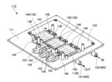
- FIG. 2 is a perspective view schematically showing a base portion with an inverter circuit arranged thereon according to the first embodiment;
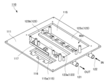
- FIG. 7 is a perspective view schematically showing a state in which the inverter circuit and the water channel cover of FIG. 6 are removed according to the first embodiment;
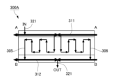
- FIG. 10 is a schematic diagram illustrating a first cooling channel according to a second embodiment
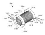
- FIG. 11 is a perspective view of a first cooling channel according to a third embodiment
- FIG. 11 is a schematic diagram illustrating a first cooling channel according to a third embodiment
- FIG. 11 is a perspective view of a first split cooling channel of a first cooling channel according to a fourth embodiment
- FIG. 11 is a perspective view of a first split cooling channel of a first cooling channel according to a fifth embodiment
- FIG. 11 is a schematic diagram illustrating a first cooling channel according to a fifth embodiment
- FIG. 1 is a perspective view of the motor unit 1 and is shown as a partial cross-sectional view.
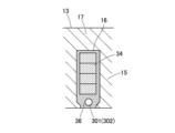
- FIG. 2 schematically shows a cross-sectional view of a plane perpendicular to the rotating shaft of the motor 10. As shown in FIG. Here, the area of one slot 16 is shown in a cross-sectional view cut along a plane perpendicular to the shaft 11 .
- the motor unit 1 has a motor 10 and an inverter section 100 (inverter device) attached to the motor 10 , which are cooled by a cooling channel 200 .
- Cooling channel 200 has a first cooling channel 300 that mainly cools motor 10 and a second cooling channel 400 that mainly cools inverter section 100 .
- the motor 10 includes a housing 20 and a rotor 12 and a stator 13 housed inside the housing 20 .
- a shaft 11 is attached to the center of the rotor 12 as an output shaft.
- the shaft 11 is rotatably supported by two left and right bearings 14a and 14b.
- the housing 20 has a first housing cover 21 , a second housing cover 22 and a third housing cover 23 .
- the third housing cover 23 is a cylindrical housing case that accommodates the rotor 12 and the stator 13 inside. At this time, the stator 13 is attached to the inner peripheral surface of the third housing cover 23 .
- the first housing cover 21 is provided in a substantially disc shape and closes the end opening on the left side of the drawing in the axial direction of the cylindrical third housing cover 23 .
- a circular through hole 24 is provided in the center of the first housing cover 21 to allow the shaft 11 to protrude.
- a bearing 14a is attached to the center of the inner side surface of the first housing cover 21 (the left side surface in the drawing) so as to rotatably support the shaft 11 .
- the second housing cover 22 is provided in a substantially disk shape and closes the end opening on the right side in the figure in the axial direction of the cylindrical third housing cover 23 .
- a bearing 14b is attached to the center of the inner side surface of the second housing cover 22 (the right side surface in the drawing) so as to rotatably support the shaft 11.
- Materials for the bearings 14a and 14b are, for example, high-carbon chromium bearing steel, stainless steel, etc. Generally, materials standardized by JIS or the like are used.
- the shaft 11 has a substantially cylindrical shape and is fixed to the center of the rotor 12 as described above.
- One end (left side in the drawing) of the shaft 11 is rotatably supported by one bearing 14a.
- the other end of the shaft 11 is rotatably supported by the other bearing 14b.
- the material of the shaft 11 is, for example, a carbon steel material, and generally a material specified by JIS is used.
- ⁇ Rotor 12> A plurality of permanent magnets are arranged inside the rotor 12 at regular intervals in the axial direction. At this time, the magnetic poles of adjacent permanent magnets are set to be different from each other.
- the stator 13 has a substantially cylindrical shape and is arranged and fixed so as to surround the outer periphery of the rotor 12 on the inner periphery of the housing 20 (more specifically, the third housing cover 23).
- a minute gap is provided between the inner peripheral surface of the stator 13 and the outer peripheral surface of the rotor 12 .
- the stator 13 is formed by laminating a plurality of electromagnetic steel sheets, which are thin magnetic bodies.
- the stator 13 has a cylindrical yoke portion 17 and a plurality of teeth portions 15 arranged from the yoke portion 17 toward the rotor 12 side. Spaces called slots 16 are provided between the teeth 15 .
- a coil 34 (for example, distributed winding) is accommodated in the slot 16, and a high thermal conductive resin sealing portion 36 filled together with the coil 34 is provided.
- the teeth 15 are provided corresponding to the permanent magnets of the rotor 12 described above, and by sequentially exciting the coils 34, the rotor 12 rotates due to attraction and repulsion with the corresponding permanent magnets.
- the high thermal conductive resin sealing portion 36 is provided to extend in the direction of the rotating shaft with respect to the outside of the stator 13 . Both ends 36a and 36b in the axial direction of the high thermal conductive resin sealing portion 36 are formed by first cooling flow passages 300 (header water passages 310) which are part of the constituent elements of the first and second housing covers 21 and 22, respectively. abut on. As a result, the heat of the highly heat-conductive resin sealing portion 36, that is, the heat of the coil 34 can be reliably transferred to the first cooling channel 300 (header channel 310).
- a first cooling channel 300 (in-coil water channel 301) is provided to extend in the axial direction in a region where the high thermal conductive resin sealing portion 36 is provided.
- the first cooling flow path 300 effectively dissipates the heat generated by the coil 34 by the refrigerant flowing inside.
- a configuration using cooling water as a coolant is exemplified.
- insert molding can be used.
- a mold structure (nested structure) corresponding to the first cooling flow path 300 is placed in the slot in which the distributed winding coil 34 is placed, and insert molding is performed to obtain a high thermal conductivity resin seal having a desired structure.
- a stop 36 and a first cooling channel 300 may be created.
- the coil internal water passage 301 is formed in the slot 16 closer to the rotor 12 than the coil 34 (lower in FIG. may be provided.
- Heat transfer can be facilitated by replacing the space (that is, slot) around the coil 34 with a highly thermally conductive resin sealing portion 36 (resin material). That is, the coil 34 and the stator 13 are tightly filled with the resin material. Further, the inner wall 10a of the first cooling channel 300 is made of the resin material. These things lead to good heat conduction between them. As a result, the cooling performance of the stator 13 can be improved, the copper loss (loss consumed by the resistance of the coil 34 itself) can be reduced, the motor output can be improved, the size of the motor unit 1 can be reduced, and the like.
- Cooling channel 200 has a first cooling channel 300 that mainly cools motor 10 and a second cooling channel 400 that mainly cools inverter section 100 .
- the second cooling flow path 400 will be described together with the description of the inverter section 100 later.
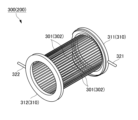
- FIG. 3 is a perspective view of the first cooling channel 300.
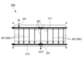
- FIG. FIG. 4 is a schematic diagram for explaining the first cooling channel 300, and is shown as a developed view. In FIG. 4, the positions where the symbols A and the symbols B match.
- the first cooling channel 300 has a plurality of in-coil water channels 301 and a header water channel 310 .
- the first cooling flow path 300 is provided with part of the configuration of the high thermal conductive resin sealing portion 36 as the water channel wall surface, but may be provided with part of other components as the water channel wall surface.
- the in-coil water passage 301 is arranged between one end and the other end in the axial direction to cool the coil 34 .
- the coil inner water channel 301 is formed in a cylindrical shape along the coil 34 with the wall surface of the high thermal conductive resin sealing portion 36 as the water channel wall surface. It is provided between the header waterway 311 and the second header waterway 312 .
- a tubular member made of a highly thermally conductive non-magnetic metal such as aluminum or an aluminum alloy, or a highly thermally conductive inorganic material can be used as the coil-inside water passage 301.
- the in-coil water passages 301 may be provided in all the slots 16 or may be provided in some of the slots 16 (for example, every other slot).
- the header water passage 310 is connected to the plurality of in-coil water passages 301 and arranged outside the coils to distribute the cooling water introduced into the in-coil water passages 301 or collect the cooling water discharged from the in-coil water passages 301 . That is, the header water channel 310 is adjusted so that the water pressure in the coil-inside water channel 301 at the portion connected to the header water channel 310 is uniform.
- the header waterway 310 has a first header waterway 311 and a second header waterway 312 .
- the first header water channel 311 and the second header water channel 312 are arranged to face each other with the stator 13 (yoke portion 17) interposed therebetween.
- the first header water passage 311 is arranged upstream of the in-coil water passages 301 and has a function of temporarily storing the cooling water to be introduced into the in-coil water passages 301 and distributing it to the plurality of in-coil water passages 301 .
- the first header water channel 311 is provided in an annular shape so as to face one end of the yoke portion 17, and a water channel for flowing cooling water is formed therein.
- In-coil water channels 301 are attached to the first header water channel 311 at regular intervals in the circumferential direction so as to face the second header water channel 312 .
- the first header water channel 311 is provided with an introduction connection portion 321 (header water channel introduction portion) for taking in cooling water from the outside (for example, a pump).
- the second header water passage 312 is arranged on the downstream side of the in-coil water passage 301, collects and temporarily stores the cooling water discharged from the in-coil water passage 301, and discharges it to the outside.
- the second header water channel 312 is provided in an annular shape so as to face the other end of the yoke portion 17, and a water channel for flowing cooling water is formed therein.
- In-coil water channels 301 are attached to the second header water channel 312 at regular intervals in the circumferential direction so as to face the first header water channel 311 .
- the second header waterway 312 is also provided with a discharge connection 322 (header waterway discharge) for sending cooling water to the outside (for example, a pump).
- the number of the introduction connection portions 321 (header channel introduction portions) and the number of discharge connection portions 322 (header channel discharge portions) are the same here, they may be different. For example, by increasing the number of discharge connection portions 322 (header channel discharge portions), it is possible to smoothly discharge the cooling water and suppress the retention of the cooling water.
- the cross-sectional area S2 of the header waterway 310 satisfies the ratio S2/S1 at least in the cross-sectional area of either the first header waterway 311 or the second header waterway 312. It is preferable that the ratio S2/S1 be satisfied in any cross-sectional area. In addition, when the cross-sectional areas S1 and S2 are not constant, it is preferable to use the smallest value for each.
- the in-slot water passage 302 provided in the slot 16, more specifically, in the high thermal conductive resin sealing portion 36 was exemplified.
- In-teeth water passages may be provided, or in-yoke water passages may be provided in the yoke portion 17 .
- the introduction connection portion 321 (header water channel introduction portion) and the discharge connection portion 322 (header water channel discharge portion) are located on different sides in the axial direction, that is, on different sides with the stator 13 sandwiched between the first header water channel 311 and the second header water channel. It is provided in the header channel 312 .
- the configuration is not limited to this, and the introduction connection portion 321 (header channel introduction portion) and the discharge connection portion 322 (header channel discharge portion) may be provided on the same side in the axial direction.
- the first header water channel 311 may be divided into a structure for introducing cooling water and a structure for discharging cooling water, and the water channel may be configured to turn back at the second header water channel 312 .
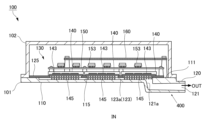
- FIG. FIG. 5 is a cross-sectional view schematically showing the internal structure of the inverter section 100.
- FIG. 6 is a perspective view schematically showing the base portion 101 in which the inverter circuit 130 is arranged.
- FIG. 7 is a perspective view schematically showing a state in which the inverter circuit 130 and the channel cover 125 of FIG. 6 are removed.
- the cooling function is mainly described, and the general configuration of the inverter device is omitted as appropriate.
- the inverter unit 100 is attached to the inverter drive type motor 10 .
- the inverter unit 100 includes a substantially box-shaped inverter case 110 made of a resin composition, an inverter circuit 130 housed therein, and a second cooling flow path for cooling the inverter circuit 130 (in particular, the power module 140). 400.
- the inverter circuit 130 has a power module 140 and other components (first and second circuit boards 150, 160, current sensor 103, etc.). Each configuration will be specifically described below.
- the inverter case 110 has a plate-like base portion 101 and a rectangular parallelepiped cover portion 102 with an open bottom covering the base portion 101, which are fixed by screws or the like.
- An inverter circuit 130 is provided inside the inverter case 110 .
- Inverter circuit 130 has power module 140 , first circuit board 150 and second circuit board 160 .
- the power module 140 includes a semiconductor chip 143, a metal heat dissipation member 145 attached to the lower surface of the semiconductor chip 143, and a lead frame 148 connected to the semiconductor chip 143, and is sealed with resin.
- the base portion 101 has a substantially rectangular shape when viewed from above, and is integrally formed into a plate shape.
- the upper surface of the base portion 101 is used as a board placement surface 111 in the drawing, and parts such as the inverter circuit 130, the first and second circuit boards 150 and 160, and the current sensor 103 (bus bar 104) are attached to the board placement surface 111. be done.
- the substrate placement surface 111 integrally has a channel wall 115 formed in a concave shape forming part of the second cooling channel 400 and a component placement portion 116 in which the current sensor 103 and the like are placed.
- the second cooling channel 400 is composed of a channel wall 115 having a recessed substrate placement surface 111 and a channel cover 125 provided to cover the upper surface of the channel wall 115 .
- the channel cover 125 is provided in a plate shape, for example, from a metal such as an aluminum alloy or a resin material. Since the channel cover 125 has a cooling water sealing function and a heat transfer function from various devices arranged in the channel cover 125, an aluminum alloy is preferable from the viewpoint of heat conduction, weight reduction, and rust prevention. Moreover, when using a resin material, a material with high thermal conductivity is preferable. A packing, a sealing material, or the like necessary for preventing leakage of cooling water is appropriately arranged between the water passage cover portion 125 and the substrate arrangement surface 111 .
- the second cooling channel 400 has a first water channel connection port 121 , a second water channel connection port 122 and a channel main body 123 .
- the flow path main body 123 is generally U-shaped as a whole, and includes a first flow path 123a extending in the left-right direction, a second flow path 123b extending in the front-rear direction, and a third flow path 123b extending in the left-right direction. and a channel 123c.
- a plate-shaped channel cover 125 made of resin is provided in the channel main body 123 , and the channel main body 123 is sealed on the upper surface of the substrate arrangement surface 111 .
- a plurality of (here, three) power modules 140 are attached to a portion of the channel cover 125 that serves as the first channel 123a.
- a film capacitor (not shown) and other electronic components are arranged in the portion of the third flow path 123c.
- An opening penetrating vertically is provided in the region where the power module 140 is attached in the water passage cover portion 125, and a pin-shaped heat radiating member 145 provided on the lower surface of the power module 140 extends from this opening to the first flow path. 123a.
- the heat radiating member 145 of the power module 140 is directly cooled by the cooling water.
- the shape of the heat radiating member 145 is not limited to a pin shape, and may be a fin shape.
- the first water channel connection port 121 is connected to the first cooling channel 300 .
- the second waterway connection port 122 functions as an inlet for cooling water.
- the first water channel connection port 121 and the second water channel connection port 122 are arranged side by side on the right side surface of the base portion 101, and are connected to the first channel 123a and the third channel 123c, respectively.
- the first channel connection port 121 extends in a pipe-like shape to the lower side or the left side of the right side of the base portion 101, and is bent upward at a connecting portion 121a to form a channel main body 123 (first is connected to the flow path 123a) of the
- the second waterway connection port 122 is also connected to the third channel 123c with the same configuration as the first waterway connection port 121 .
- the cooling water introduced from the second water channel connection port 122 passes through the channel main body 123 (the first to third channels 123a to 123c), It cools the module 140 , the film capacitor, and the like, and supplies it from the first waterway connection port 121 to the first cooling channel 300 .
- Inverter unit 100 and motor 10 may be cooled through independent paths. That is, the flow paths of the first cooling flow path 300 and the second cooling flow path 400 may be provided independently without being connected.
- Inverter case 110 is made of the third resin composition.
- the third resin composition is a thermosetting resin such as a phenolic resin or an epoxy resin.
- the base portion 101 and the cover portion 102 that constitute the inverter case 110 are made of a cured thermosetting resin.
- the base portion 101 and the cover portion 102 may be made of the same material, or may be made of different materials. Specifically, the same material as the first resin composition and the second resin composition described above can be used as the thermosetting resin.
- the inverter case 110 (the base portion 101 and the cover portion 102) of resin
- the adhesion to other members can be improved and the weight can be reduced.
- it since it is made of resin, it has excellent moldability and workability, which greatly increases the degree of freedom in design, as well as absorbs vibration and reduces noise.
- the filler content in the thermosetting resin is 60% by volume or more, preferably 70% or more. This makes it possible to realize further weight reduction and high mechanical strength.
- cooling channel 200 can be adopted as various embodiments (modifications) as the cooling channel 200 .
- modifications can be adopted as the cooling channel 200 .
- Such embodiments are described below.
- different configurations and functions of the first cooling flow path 300 will be mainly described, and descriptions of other configurations and functions will be omitted as appropriate.
- FIG. 8 is a schematic diagram illustrating the first cooling channel 300A.
- the first cooling channel 300A has a first header water channel 311A and a second header water channel 312A. From the first header water channel 311A toward the second header water channel 312A, there are two systems of water channels (in-coil water channels), that is, a first in-coil turn-up water channel 305 and a second in-coil turn-up water channel 306 .
- the first in-coil turn-back water passage 305 passes through the slot 16 (inside the high thermal conductive resin sealing portion 36) in a so-called unicursal shape, and when it exits the slot 16, the first header water passage 311 and the second header water passage 312 are formed. It is folded back a predetermined number of times without being connected to the second header waterway 312 and finally connected to the second header waterway 312 .
- the second in-coil turn-back waterway 306 also passes through the slot 16 (inside the high thermal conductive resin sealing portion 36) in a so-called unicursal shape, and when it exits the slot 16, the first header waterway 311 and the second header waterway 311 are formed. It is folded back a predetermined number of times without being connected to the water channel 312 and finally connected to the second header water channel 312 .
- the total cross-sectional area of a plurality of in-coil water passages (that is, the first in-coil turn-up water passage 305 and the second in-coil turn-up water passage 306) is S1
- the header water passage 310 (first header water passage 311, second header water passage 310) is 312)
- the ratio S2/S1 between S1 and S2 is 0.5 or more
- S2 is the cross-sectional area of the plane perpendicular to the moving direction of the cooling water.
- FIG. 9 is a perspective view of the first cooling channel 1300.
- FIG. 10 is a schematic diagram for explaining the first cooling channel 1300, and is shown as a developed view. In FIG. 10, the positions where the symbols A and the symbols B match.
- the first cooling channel 1300 has a first split cooling channel 1300A and a second split cooling channel 1300B.
- the first split cooling channel 1300A and the second split cooling channel 1300B are composed of water channels independent of each other. It can also be said that the first cooling channel 300 of the first embodiment is vertically divided into two.
- the first divided cooling channel 1300A has a semi-arc first header channel 1311A, a semi-arc second header channel 1312A, and a plurality of in-coil channels 1301A.
- the first header waterway 1311A and the second header waterway 1312A are arranged to face each other with the stator 13 interposed therebetween.
- the first header waterway 1311A is arranged on the upstream side of the in-coil waterway 1301A, and has a function of temporarily storing the cooling water to be introduced into the in-coil waterway 1301A and distributing it to the plurality of in-coil waterway 1301A.
- In-coil water passages 1301A are attached to the first header water passage 1311A at regular intervals in the circumferential direction so as to face the second header water passage 1312A.
- the first header water channel 1311A is provided with an introduction connection portion 1321A for taking in cooling water from the outside.
- the second header waterway 1312A is arranged downstream of the in-coil waterway 1301A, collects and temporarily stores the cooling water discharged from the in-coil waterway 1301A, and discharges it to the outside.
- In-coil water passages 1301A are attached to the second header water passage 1312A at regular intervals in the circumferential direction so as to face the first header water passage 1311A.
- the second header water channel 1312A is provided with a discharge connection portion 1322A for sending cooling water to the outside.
- the second divided cooling channel 1300B has a semi-arc first header channel 1311B, a semi-arc second header channel 1312B, and a plurality of in-coil channels 1301B.
- the first header waterway 1311B and the second header waterway 1312B are arranged to face each other with the stator 13 interposed therebetween.
- the first header waterway 1311B is arranged on the upstream side of the in-coil waterway 1301B, and has the function of temporarily storing cooling water to be introduced into the in-coil waterway 1301B and distributing it to the plurality of in-coil waterways 1301B.
- In-coil water passages 1301B are attached to the first header water passage 1311B at regular intervals in the circumferential direction so as to face the second header water passage 1312B.
- the first header water channel 1311B is provided with an introduction connection portion 1321B for taking in cooling water from the outside.
- the second header water channel 1312B is arranged on the downstream side of the in-coil water channel 1301B, collects and temporarily stores the cooling water discharged from the in-coil water channel 1301B, and discharges it to the outside.
- In-coil water passages 1301B are attached to the second header water passage 1312B at regular intervals in the circumferential direction so as to face the first header water passage 1311B.
- the second header water channel 1312B is provided with a discharge connection 1322B for sending cooling water to the outside.
- the total cross-sectional area of the plurality of coil internal water channels 1301A is S1, which is perpendicular to the direction of movement of the cooling water in the header channel 1310 (first header channel 1311A, second header channel 1312A).
- a ratio S2/S1 between S1 and S2 is 0.5 or more, where S2 is the cross-sectional area of the flat surface.
- the ratio S2/S1 of the second split cooling channel 1300B is 0.5 or more.
- the first cooling flow path 1300 is composed of a first divided cooling flow path 1300A and a second divided cooling flow path 1300B, which are constructed from mutually independent waterway systems. This makes it possible to provide redundancy in case of water channel trouble (clogging, etc.). That is, even if one of the water passage systems fails, the other water passage system cools the motor unit 1, so the motor unit 1 does not stop immediately. That is, it is possible to operate in a low heat generation state with a low load for a certain period of time. For example, when the motor unit 1 is mounted on a vehicle, the vehicle can be driven to a repairable location.
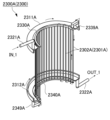
- the first cooling channel 2300 of this embodiment will be described with reference to FIG.
- the first cooling channel 2300 has two water channel systems obtained by vertically dividing the first cooling channel 2300 into two.
- the split cooling channel 2300A will be described, and the description of the other water channel system (second split cooling channel) will be omitted.
- the first split cooling channel 2300A has a semi-arc first header channel 2311A, a semi-arc second header channel 1312A, and an in-coil channel 2301A.
- An introduction connection portion 2321A is provided at one end of the semi-arc-shaped first header channel 2311A.
- the first header waterway 2311A and the in-coil waterway 2301A are connected by a first connecting portion 2339A at the other end of the semi-arc-shaped first header waterway 2311A.
- a discharge connection portion 2322A is provided at one end (however, the side on which the first connection portion 2339A is provided) of the semi-arc second header channel 2312A.
- the second header waterway 2312A and the in-coil waterway 2301A are connected by a second connecting portion 2349A at the other end of the semi-arc-shaped second header waterway 2312A (the side where the lead-in connection portion 2321A is provided).
- the second header waterway 1312A and the in-coil waterway 2301A are connected by a second connecting portion 2349A.
- the in-coil water channel 2301A has an in-slot water channel 2302A provided in each slot 16, and a first folded portion 2330A and a second folded portion 2340A that fold back in the region protruding from the slot 16 in a unicursal pattern.
- the in-slot water passages 2302A are alternately connected.
- the first folded portion 2330A and the second folded portion 2340A may be provided only in the portion where the in-slot water passage 2302A is connected, and may be omitted in the portion where they are not connected.
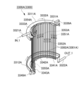
- FIG. 12 is a perspective view of a first split cooling channel 3300A of the first cooling channel 3300.
- FIG. FIG. 13 is a schematic diagram for explaining the first cooling flow path 3300 and is shown as a developed view. In FIG. 13, the positions where the symbols A and the symbols B match.
- the first cooling channel 3300 of the present embodiment is a modified example of the first cooling channel 2300 of the fourth embodiment, in which a plurality of routes are taken as one unit, and a plurality of routes are taken as one unit, and the first cooling channel 3300 is divided from one end to the other end or the other end. It is configured to have a path for turning back the cooling water unit by unit from end to end.
- the route is configured with four in-slot water channels 3302A as one unit.
- the cooling water introduced from the introduction connection portion 3321A into the first header water channel 3311A is introduced into the first upstream folded portion 3331A via the first connecting portion 3339A.
- Four in-slot water channels 3302A (also referred to as first folding units 3351A) are connected from the first upstream folded portion 3331A toward the first downstream folded portion 3341A to consolidate the water channels.
- a first folded unit 3351A is connected to the first downstream folded portion 3341A, and four in-slot water channels 3302A (also referred to as a second folded unit 3352A) are connected toward the second upstream folded portion 3332A.
- a second folded unit 3352A is connected to the second upstream folded portion 3332A, and four in-slot water channels 3302A (also referred to as a third folded unit 3353A) are connected toward the second downstream folded portion 3342A.
- a third folded unit 3353A is connected to the second downstream folded portion 3342A, and four in-slot water channels 3302A (also referred to as a fourth folded unit 3354A) are connected toward the third upstream folded portion 3333A.
- a third turn-back unit 3354A is connected to the third upstream turn-back portion 3333A, and four in-slot water channels 3302A (also referred to as fifth turn-back units 3355A) are connected toward the third downstream-side turn-back portion 3343A.
- a second header water channel 3312A is connected to the third downstream folded portion 3343A via a second connecting portion 3349A.
- a discharge connection portion 3322A is connected to the second header channel 3312A at the opposite end of the second connection portion 3349A.
- first to fourth turn-back units 3351B to 3354B are provided between the first header water channel 3311B and the second header water channel 3312B. and are provided.
- Cooling water introduced into the first header water passage 3311B from the introduction connection portion 3321B is introduced into the first upstream folded portion 3331B via the first connecting portion 3339B, and is introduced into the four in-slot water passages 3302B (first folded unit 3351B). ) to the first downstream folding portion 3341B.
- the waterways are once aggregated and distributed to four in-slot waterways 3302B (also referred to as second turn-up units 3352B) toward the second upstream side turn-up portion 3332B.
- the water channels are once aggregated and distributed to four in-slot channels 3302B (third folded units 3353B) toward the second downstream folded portion 3342B.
- the waterways are once aggregated and distributed to the four in-slot waterways 3302B (fourth turn-up unit 3354B) toward the third upstream side turn-up portion 3333B.
- the water channels are once aggregated and distributed to the four in-slot channels 3302B (fifth folded unit 3355B) toward the third downstream folded portion 3343B.
- the waterway aggregated at the third downstream turn-back portion 3343B is connected to the discharge connection portion 3322B via the second connecting portion 3349B and the second header waterway 3312B.
Landscapes
- Engineering & Computer Science (AREA)
- Power Engineering (AREA)
- Microelectronics & Electronic Packaging (AREA)
- Physics & Mathematics (AREA)
- Thermal Sciences (AREA)
- Manufacturing & Machinery (AREA)
- Motor Or Generator Cooling System (AREA)
Abstract
Description
特許文献1に開示の技術では、ステータのティース部に集中巻きしたコイルを、ティース部間のスロットに収容した回転電機において、スロットの内部空間に軸方向に延びる複数のパイプを並列配置し、かつこれらパイプの隙間及びパイプと前記コイルとの隙間に樹脂材料を充填して、ステータ内周側に向けて開口するスロットを閉塞する樹脂層を形成し、パイプ内に冷媒を流している。
[1]
ヨーク部と、前記ヨーク部から延出するティース部と、前記ティース部間に形成されたスロット内に収容されたコイルと、前記コイルを冷却する冷却水路と、を有するステータであって、
前記冷却水路は、
軸方向の一端から他端の間に配置され前記コイルを冷却するコイル内水路と、
複数の前記コイル内水路に連結され、前記コイル外に配置され、前記コイル内水路に導入する冷却水を分配する又は前記コイル内水路から排出された冷却水を集約するヘッダ水路と、
を有し、
前記コイル内水路の断面積の合計をS1、前記ヘッダ水路における前記冷却水の移動方向に対して垂直な面の断面積をS2としたときに、
前記S1と前記S2の比S2/S1が0.5以上である、ステータ。
[2]
前記冷却水路は、相互に独立している複数の系統を備える、[1]に記載のステータ。
[3]
前記コイル内水路は、前記スロット内に配置されているスロット内水路を有している、[1]または[2]に記載のステータ。
[4]
前記コイル内水路は、前記ティース部内に配置されているティース内水路を有している、[1]から[3]までのいずれか1に記載のステータ。
[5]
前記コイル内水路は、前記ヨーク部内に配置されているヨーク内水路を有している、[1]から[4]までのいずれか1に記載のステータ。
[6]
前記コイル内水路は、複数経路を1ユニットとして、前記一端から前記他端又は前記他端から前記一端へユニット単位で冷却水を折り返す経路を有して構成されている、[1]から[5]までのいずれか1に記載のステータ。
[7]
前記ヘッダ水路は、
外部から冷却水を導入するヘッダ水路導入部と、
外部に冷却水を排出するヘッダ水路排出部と、
を有する、[1]から[6]までのいずれか1に記載のステータ。
[8]
前記ヘッダ水路導入部と前記ヘッダ水路排出部とは軸方向の異なる側に設けられている、[7]に記載のステータ。
[9]
前記ヘッダ水路導入部と前記ヘッダ水路排出部とは軸方向の同じ側に設けられている、[7]に記載のステータ。
[10]
前記ヘッダ水路導入部の数と前記ヘッダ水路排出部の数は同じである、[7]から[9]までのいずれか1に記載のステータ。
[11]
前記ヘッダ水路導入部の数と前記ヘッダ水路排出部の数は異なる、[7]から[9]までのいずれか1に記載のステータ。
[12]
前記コイル内水路および前記ヘッダ水路は、樹脂組成物が硬化した樹脂層を有して構成されており、
前記樹脂組成物は、エポキシ樹脂およびフェノール樹脂からなる群より選択される1種または2種の熱硬化性樹脂からなる、[1]から[11]までのいずれか1に記載のステータ。
[13]
前記ヘッダ水路は、前記ヘッダ水路に連結する部分における前記コイル内水路の水圧が均等になるように調整する、[1]から[12]までのいずれか1に記載のステータ。
[14]
ヨーク部と、前記ヨーク部から延出するティース部と、前記ティース部間に形成されたスロットと、前記スロット内に収容されたコイルと、前記コイルを冷却する冷却水路と、を有するステータであって、
前記冷却水路は、
前記ヨーク部の軸方向の一端から他端の間に配置され、複数経路を1ユニットとして、前記一端から前記他端又は前記他端から前記一端へユニット単位で冷却水を折り返す経路を有して構成されている、ステータ。
[15]
前記冷却水を導入するための外部冷却水導入経路と、前記冷却水を排出するために接続されるに外部冷却水排出経路とは、経路数が異なる、請求項14に記載のステータ。
[16]
[1]から[15]までのいずれか1に記載のステータが有する冷却水路と、
前記冷却水路に連結されており、前記ステータを有するモータと一体に設けられたインバータが備えるパワーモジュールを冷却するパワーモジュール冷却水路と、
を有する構造体。
[17]
前記パワーモジュール冷却水路は、前記パワーモジュールが備える半導体素子回路を冷却する、[16]に記載の構造体。
[18]
前記パワーモジュール冷却水路は、前記インバータが備えるコンデンサを冷却する、[16]または[17]に記載の構造体。
本実施形態では、回転電機(電動機、発電機または電動機/発電機の両用機)としてインバータ型のモータに適用した例を説明する。図1はモータユニット1の斜視図であって一部断面図として示している。図2はモータ10の回転軸に垂直な面の断面図を模式的に示している。ここでは、シャフト11に垂直な面で切断した断面図において一つのスロット16の領域を示している。
モータユニット1は、モータ10と、モータ10に取り付けられたインバータ部100(インバータ装置)とを有し、それらは冷却流路200により冷却される。冷却流路200は、主にモータ10を冷却する第1冷却流路300と、主にインバータ部100を冷却する第2冷却流路400とを有する。
モータ10は、ハウジング20と、ハウジング20の内部に収容されたロータ12及びステータ13とを備える。ロータ12の中心には出力軸としてシャフト11が取り付けられる。シャフト11は、左右二つのベアリング14a、14bにより回転自在に支持されている。
ハウジング20は、第1ハウジングカバー21と、第2ハウジングカバー22と、第3ハウジングカバー23とを有する。
ベアリング14a、14bの材料は、例えば、高炭素クロム軸受鋼やステンレス鋼などであって、一般にはJIS規格等で規格化されている材料が用いられる。
シャフト11は、略円柱形状を呈しており、上述のようにロータ12の中心に固定されている。シャフト11の一方(図示左側)の端部が、一方のベアリング14aに回動自在に支持されている。シャフト11の他方の端部が、他方のベアリング14bに回動自在に支持されている。シャフト11の材質は、例えば炭素鋼鋼材であって、一般にはJIS規定されている材料が用いられる。
ロータ12には、内部に軸周方向に等間隔に配置された複数の永久磁石が配置されている。このとき、隣り合う永久磁石の磁極が互いに異なるように設置されている。
ステータ13は、略円筒型であって、ハウジング20(より具体的には第3ハウジングカバー23)の内周において、ロータ12の外周を取り囲むように配置され固定されている。ステータ13の内周面とロータ12の外周面との間には微少な間隙(エアギャップ)が設けられている。
冷却流路200は、主にモータ10を冷却する第1冷却流路300と、主にインバータ部100を冷却する第2冷却流路400とを有する。第2冷却流路400については後述のインバータ部100の説明と共に説明する。
図3は第1冷却流路300の斜視図である。図4は第1冷却流路300を説明する模式図であって、展開図として示している。図4において、符号A同士、符号B同士が一致する位置となる。
コイル内水路301は、軸方向の一端から他端の間に配置されコイル34を冷却する。具体的には、コイル内水路301は、各スロット16内の高熱伝導樹脂封止部36において、高熱伝導樹脂封止部36の壁面を水路壁面として筒状にコイル34に沿うようにして第1ヘッダ水路311と第2ヘッダ水路312の間に設けられている。また、コイル内水路301として、アルミニウムまたはアルミニウム合金のような高熱伝導性の非磁性金属や、高熱伝導性の無機材料からなる筒状部材を用いることができる。また、コイル内水路301は、全てのスロット16に設けられてもよいし、一部のスロット16(例えば一つおき)に設けられてもよい。
ヘッダ水路310は、複数のコイル内水路301に連結され、コイル外に配置され、コイル内水路301に導入する冷却水を分配する又はコイル内水路301から排出された冷却水を集約する。すなわち、ヘッダ水路310は、ヘッダ水路310に連結する部分におけるコイル内水路301の水圧が均等になるように調整する。
複数のコイル内水路301の断面積の合計をS1、ヘッダ水路310(第1ヘッダ水路311、第2ヘッダ水路312)における冷却水の移動方向に対して垂直な面の断面積をS2としたときに、S1とS2の比S2/S1が0.5以上である。ここで、冷却水の移動方向とは、「ヘッダ水路310の延在方向(配置方向)」とも言える。比S2/S1は、好ましくは0.7以上であり、より好ましくは1.0以上である。ヘッダ水路310の断面積S2は、少なくとも第1ヘッダ水路311又は第2ヘッダ水路312のいずれかの断面積において、上記比S2/S1を満たすが、第1ヘッダ水路311及び第2ヘッダ水路312のいずれの断面積においても上記比S2/S1を満たすことが好ましい。なお、断面積S1、S2が一定でない場合、それぞれにおいて最も小さい値を用いることが好ましい。
図5~図7にインバータ部100を示す。図5はインバータ部100の内部構造を模式的に示した断面図である。図6はインバータ回路130を配置した状態のベース部101を模式的に示した斜視図である。図7は、図6のインバータ回路130及び水路蓋部125を取り除いた状態を模式的に示した斜視図である。本実施形態では、主に冷却機能に着目して説明し、インバータ装置の一般的な構成については適宜省略して示している。
以下、各構成を具体的に説明する。
インバータケース110は、板状のベース部101と、ベース部101を覆う底部が開口した直方体形状でカバー部102とを有し、それらはネジ等により固定されている。インバータケース110の内部にはインバータ回路130が設けられている。
インバータ回路130は、パワーモジュール140と、第1の回路基板150および第2の回路基板160とを有する。パワーモジュール140は、半導体チップ143と、半導体チップ143の下面に取り付けられた金属製の放熱部材145と、半導体チップ143に接続するリードフレーム148とを備え樹脂により封止されている。
ベース部101は、上面視で略矩形であって板状に一体成形により設けられている。
ベース部101は図示で上側の面を基板配置面111としており、基板配置面111にインバータ回路130や第1及び第2の回路基板150、160、電流センサー103(バスバー104)等の部品が取り付けられる。基板配置面111は、第2冷却流路400の一部を構成する凹状に形成された水路壁115と、電流センサー103等を配置する部品配置部116とを一体に有する。
第2冷却流路400は、基板配置面111が凹状に形成された水路壁115と、水路壁115の上面を蓋するように設けられた水路蓋部125とにより構成されている。水路蓋部125は、例えばアルミニウム合金等の金属や樹脂材料で板状に設けられている。水路蓋部125は冷却水のシール機能を担うとともに水路蓋部125に配置する各種機器からの伝熱機能を担うことから、熱伝導、軽量化、防錆の観点からアルミニウム合金が好ましい。また、樹脂材料を用いる場合には、熱伝導率が高い材料が好ましい。なお、水路蓋部125と基板配置面111との間には、冷却水の漏れを防止する為に必要なパッキンやシール材などが適宜配置される。
インバータケース110は第3樹脂組成物からなる。具体的には、第3樹脂組成物は熱硬化性樹脂であって、例えばフェノール樹脂またはエポキシ樹脂からなる。インバータケース110を構成するベース部101とカバー部102は、熱硬化性樹脂の硬化物で形成される。ベース部101とカバー部102は同じ材料で形成されてもよいし、異なる材料で形成されてもよい。具体的には、熱硬化性樹脂として、上述した第1樹脂組成物や第2樹脂組成物と同様の材料を用いることができる。
なお、熱硬化性樹脂に含まれるフィラーの含有率は60体積%以上であり、好ましくは70%以上である。これによって、一層の軽量化と高い機械的強度を実現できる。
図8を参照して本実施形態の冷却流路200の第1冷却流路300Aについて説明する。図8は、第1冷却流路300Aを説明する模式図である。第1冷却流路300Aは、第1ヘッダ水路311Aと第2ヘッダ水路312Aとを有する。第1ヘッダ水路311Aから第2ヘッダ水路312Aに向けて2系統の水路(コイル内水路)、すなわち、第1コイル内折り返し水路305と第2コイル内折り返水路306とを有する。
図9~10を参照して第1冷却流路1300について説明する。図9は第1冷却流路1300の斜視図である。図10は第1冷却流路1300を説明する模式図であって、展開図として示している。図10において、符号A同士、符号B同士が一致する位置となる。
図11を参照して本実施形態の第1冷却流路2300について説明する。第1冷却流路2300は、第3の実施形態と同様に、第1冷却流路2300を縦に2分割した二つの水路系を有する構成であり、以下では、片方の水路系である第1分割冷却流路2300Aについて説明し、他方の水路系(第2分割冷却流路)については説明を省略する。
図12および図13を参照して本実施形態の第1冷却流路3300について説明する。
図12は第1冷却流路3300の第1分割冷却流路3300Aの斜視図である。図13は第1冷却流路3300を説明する模式図であって、展開図として示している。図13において、符号A同士、符号B同士が一致する位置となる。
10 モータ
12 ロータ
13 ステータ
15 ティース部
16 スロット
17 ヨーク部
20 ハウジング
34 コイル
36 高熱伝導樹脂封止部
100 インバータ部
101 ベース部
102 カバー部
123 流路本体
130 インバータ回路
140 パワーモジュール
143 半導体チップ
200 冷却流路
300、300A、1300、2300、3300 第1冷却流路
301、1301A、1301B、2301A、3301A コイル内水路
302、2302A、3302A、3302B スロット内水路
305 第1コイル内折り返し水路
306 第2コイル内折り返し水路
310、1310 ヘッダ水路
311、311A、1311A、1311B、2311A、3311A、3311B 第1ヘッダ水路
312、312A、1312A、1312B、2312A、3312A、3312B 第2ヘッダ水路
321、1321A、1321B、2321A、3321A、3321B 導入接続部
322、1322A、1322B、2322A,3322A、3321B 排出接続部
400 第2冷却流路
1300A、2300A、3300A 第1分割冷却流路
1300B、3300B 第2分割冷却流路
3331A、3331B 第1上流側折り返し部
3332A、3332B 第2上流側折り返し部
3333A、3333B 第3上流側折り返し部
3341A、3341B 第1下流側折り返し部
3342A、3342B 第2下流側折り返し部
3343A、3343B 第3下流側折り返し部
3351A、3351B 第1折り返しユニット
3352A、3352B 第2折り返しユニット
3353A、3353B 第3折り返しユニット
3354A、3354B 第4折り返しユニット
3355A、3355B 第5折り返しユニット
Claims (18)
- ヨーク部と、前記ヨーク部から延出するティース部と、前記ティース部間に形成されたスロット内に収容されたコイルと、前記コイルを冷却する冷却水路と、を有するステータであって、
前記冷却水路は、
軸方向の一端から他端の間に配置され前記コイルを冷却するコイル内水路と、
複数の前記コイル内水路に連結され、前記コイル外に配置され、前記コイル内水路に導入する冷却水を分配する又は前記コイル内水路から排出された冷却水を集約するヘッダ水路と、
を有し、
前記コイル内水路の断面積の合計をS1、前記ヘッダ水路における前記冷却水の移動方向に対して垂直な面の断面積をS2としたときに、
前記S1と前記S2の比S2/S1が0.5以上である、ステータ。 - 前記冷却水路は、相互に独立している複数の系統を備える、請求項1に記載のステータ。
- 前記コイル内水路は、前記スロット内に配置されているスロット内水路を有している、請求項1または2に記載のステータ。
- 前記コイル内水路は、前記ティース部内に配置されているティース内水路を有している、請求項1または2に記載のステータ。
- 前記コイル内水路は、前記ヨーク部内に配置されているヨーク内水路を有している、請求項1または2に記載のステータ。
- 前記コイル内水路は、複数経路を1ユニットとして、前記一端から前記他端又は前記他端から前記一端へユニット単位で冷却水を折り返す経路を有して構成されている、請求項1または2に記載のステータ。
- 前記ヘッダ水路は、
外部から冷却水を導入するヘッダ水路導入部と、
外部に冷却水を排出するヘッダ水路排出部と、
を有する、請求項1または2に記載のステータ。 - 前記ヘッダ水路導入部と前記ヘッダ水路排出部とは軸方向の異なる側に設けられている、請求項7に記載のステータ。
- 前記ヘッダ水路導入部と前記ヘッダ水路排出部とは軸方向の同じ側に設けられている、請求項7に記載のステータ。
- 前記ヘッダ水路導入部の数と前記ヘッダ水路排出部の数は同じである、請求項7に記載のステータ。
- 前記ヘッダ水路導入部の数と前記ヘッダ水路排出部の数は異なる、請求項7に記載のステータ。
- 前記コイル内水路および前記ヘッダ水路は、樹脂組成物が硬化した樹脂層を有して構成されており、
前記樹脂組成物は、エポキシ樹脂およびフェノール樹脂からなる群より選択される1種または2種の熱硬化性樹脂からなる、請求項1または2に記載のステータ。 - 前記ヘッダ水路は、前記ヘッダ水路に連結する部分における前記コイル内水路の水圧が均等になるように調整する、請求項1または2に記載のステータ。
- ヨーク部と、前記ヨーク部から延出するティース部と、前記ティース部間に形成されたスロットと、前記スロット内に収容されたコイルと、前記コイルを冷却する冷却水路と、を有するステータであって、
前記冷却水路は、
前記ヨーク部の軸方向の一端から他端の間に配置され、複数経路を1ユニットとして、前記一端から前記他端又は前記他端から前記一端へユニット単位で冷却水を折り返す経路を有して構成されている、ステータ。 - 前記冷却水を導入するための外部冷却水導入経路と、前記冷却水を排出するために接続されるに外部冷却水排出経路とは、経路数が異なる、請求項14に記載のステータ。
- 請求項1または2に記載のステータが有する冷却水路と、
前記冷却水路に連結されており、前記ステータを有するモータと一体に設けられたインバータが備えるパワーモジュールを冷却するパワーモジュール冷却水路と、
を有する構造体。 - 前記パワーモジュール冷却水路は、前記パワーモジュールが備える半導体素子回路を冷却する、請求項16に記載の構造体。
- 前記パワーモジュール冷却水路は、前記インバータが備えるコンデンサを冷却する、請求項16に記載の構造体。
Priority Applications (4)
| Application Number | Priority Date | Filing Date | Title |
|---|---|---|---|
| JP2023524635A JP7452764B2 (ja) | 2021-10-27 | 2022-10-21 | ステータ及び構造体 |
| EP22886898.0A EP4425769A4 (en) | 2021-10-27 | 2022-10-21 | STATOR AND STRUCTURE |
| KR1020247017009A KR20240090775A (ko) | 2021-10-27 | 2022-10-21 | 스테이터 및 구조체 |
| CN202280071485.6A CN118160198A (zh) | 2021-10-27 | 2022-10-21 | 定子和结构体 |
Applications Claiming Priority (2)
| Application Number | Priority Date | Filing Date | Title |
|---|---|---|---|
| JP2021175415 | 2021-10-27 | ||
| JP2021-175415 | 2021-10-27 |
Publications (1)
| Publication Number | Publication Date |
|---|---|
| WO2023074571A1 true WO2023074571A1 (ja) | 2023-05-04 |
Family
ID=86159452
Family Applications (1)
| Application Number | Title | Priority Date | Filing Date |
|---|---|---|---|
| PCT/JP2022/039299 Ceased WO2023074571A1 (ja) | 2021-10-27 | 2022-10-21 | ステータ及び構造体 |
Country Status (5)
| Country | Link |
|---|---|
| EP (1) | EP4425769A4 (ja) |
| JP (1) | JP7452764B2 (ja) |
| KR (1) | KR20240090775A (ja) |
| CN (1) | CN118160198A (ja) |
| WO (1) | WO2023074571A1 (ja) |
Cited By (3)
| Publication number | Priority date | Publication date | Assignee | Title |
|---|---|---|---|---|
| EP4583376A1 (en) | 2024-01-04 | 2025-07-09 | Toyota Jidosha Kabushiki Kaisha | Motor unit |
| EP4583377A1 (en) | 2024-01-04 | 2025-07-09 | Toyota Jidosha Kabushiki Kaisha | Motor unit |
| EP4589823A1 (en) | 2024-01-18 | 2025-07-23 | Toyota Jidosha Kabushiki Kaisha | Motor unit |
Citations (11)
| Publication number | Priority date | Publication date | Assignee | Title |
|---|---|---|---|---|
| JPS5627874U (ja) * | 1979-08-08 | 1981-03-16 | ||
| JPH0993869A (ja) * | 1995-09-28 | 1997-04-04 | Mitsubishi Electric Corp | 液冷構造を有する回転機械 |
| JPH09163681A (ja) * | 1995-12-12 | 1997-06-20 | Hitachi Ltd | 電気車用回転電機 |
| JPH1127881A (ja) * | 1997-07-04 | 1999-01-29 | Hitachi Ltd | 液冷回転機 |
| JP2009284755A (ja) * | 2008-04-18 | 2009-12-03 | Abb Oy | 電気機械のための冷却要素 |
| JP4496710B2 (ja) | 2003-03-27 | 2010-07-07 | 日産自動車株式会社 | 回転電機の冷却構造 |
| JP2011015578A (ja) * | 2009-07-03 | 2011-01-20 | Fanuc Ltd | 電動機冷却装置 |
| JP2015216793A (ja) * | 2014-05-12 | 2015-12-03 | 住友重機械工業株式会社 | リニアモータ用電機子 |
| JP2016077117A (ja) * | 2014-10-08 | 2016-05-12 | 三菱自動車工業株式会社 | 車両用モータ装置 |
| JP2020532253A (ja) * | 2017-05-19 | 2020-11-05 | マーレ インターナショナル ゲゼルシャフト ミット ベシュレンクテル ハフツングMAHLE International GmbH | 電気機械 |
| JP2021175415A (ja) | 2015-10-20 | 2021-11-04 | セルキュイティー インコーポレイテッド | 初代細胞試料を調製する方法 |
Family Cites Families (8)
| Publication number | Priority date | Publication date | Assignee | Title |
|---|---|---|---|---|
| US6933633B2 (en) * | 2001-10-03 | 2005-08-23 | Nissan Motor Co., Ltd. | Rotating electric machine and cooling structure for rotating electric machine |
| JP2005160156A (ja) * | 2003-11-21 | 2005-06-16 | Nissan Motor Co Ltd | 電動機のステータ構造及びその製造方法 |
| US20060043801A1 (en) * | 2004-08-27 | 2006-03-02 | Caterpillar Inc. | Liquid cooled switched reluctance electric machine |
| JP5470015B2 (ja) * | 2009-12-04 | 2014-04-16 | 株式会社日立製作所 | 回転電機 |
| DE102016001838A1 (de) * | 2016-02-17 | 2017-08-17 | Audi Ag | Elektrische Maschine für ein Kraftfahrzeug, Spulenträger für eine elektrische Maschine und Kraftfahrzeug |
| EP3499685B1 (en) * | 2017-12-13 | 2021-10-20 | FERRARI S.p.A. | Stator of an electric machine provided with fluid cooling |
| DE102018219817A1 (de) * | 2018-11-19 | 2020-05-20 | Mahle International Gmbh | Elektrische Maschine, insbesondere für ein Fahrzeug |
| CN112636499A (zh) * | 2020-12-29 | 2021-04-09 | 东风德纳车桥有限公司 | 油冷定子、电机、电驱动桥和汽车 |
-
2022
- 2022-10-21 WO PCT/JP2022/039299 patent/WO2023074571A1/ja not_active Ceased
- 2022-10-21 EP EP22886898.0A patent/EP4425769A4/en active Pending
- 2022-10-21 CN CN202280071485.6A patent/CN118160198A/zh active Pending
- 2022-10-21 KR KR1020247017009A patent/KR20240090775A/ko active Pending
- 2022-10-21 JP JP2023524635A patent/JP7452764B2/ja active Active
Patent Citations (11)
| Publication number | Priority date | Publication date | Assignee | Title |
|---|---|---|---|---|
| JPS5627874U (ja) * | 1979-08-08 | 1981-03-16 | ||
| JPH0993869A (ja) * | 1995-09-28 | 1997-04-04 | Mitsubishi Electric Corp | 液冷構造を有する回転機械 |
| JPH09163681A (ja) * | 1995-12-12 | 1997-06-20 | Hitachi Ltd | 電気車用回転電機 |
| JPH1127881A (ja) * | 1997-07-04 | 1999-01-29 | Hitachi Ltd | 液冷回転機 |
| JP4496710B2 (ja) | 2003-03-27 | 2010-07-07 | 日産自動車株式会社 | 回転電機の冷却構造 |
| JP2009284755A (ja) * | 2008-04-18 | 2009-12-03 | Abb Oy | 電気機械のための冷却要素 |
| JP2011015578A (ja) * | 2009-07-03 | 2011-01-20 | Fanuc Ltd | 電動機冷却装置 |
| JP2015216793A (ja) * | 2014-05-12 | 2015-12-03 | 住友重機械工業株式会社 | リニアモータ用電機子 |
| JP2016077117A (ja) * | 2014-10-08 | 2016-05-12 | 三菱自動車工業株式会社 | 車両用モータ装置 |
| JP2021175415A (ja) | 2015-10-20 | 2021-11-04 | セルキュイティー インコーポレイテッド | 初代細胞試料を調製する方法 |
| JP2020532253A (ja) * | 2017-05-19 | 2020-11-05 | マーレ インターナショナル ゲゼルシャフト ミット ベシュレンクテル ハフツングMAHLE International GmbH | 電気機械 |
Non-Patent Citations (1)
| Title |
|---|
| See also references of EP4425769A4 |
Cited By (3)
| Publication number | Priority date | Publication date | Assignee | Title |
|---|---|---|---|---|
| EP4583376A1 (en) | 2024-01-04 | 2025-07-09 | Toyota Jidosha Kabushiki Kaisha | Motor unit |
| EP4583377A1 (en) | 2024-01-04 | 2025-07-09 | Toyota Jidosha Kabushiki Kaisha | Motor unit |
| EP4589823A1 (en) | 2024-01-18 | 2025-07-23 | Toyota Jidosha Kabushiki Kaisha | Motor unit |
Also Published As
| Publication number | Publication date |
|---|---|
| KR20240090775A (ko) | 2024-06-21 |
| JP7452764B2 (ja) | 2024-03-19 |
| EP4425769A4 (en) | 2025-11-05 |
| JPWO2023074571A1 (ja) | 2023-05-04 |
| EP4425769A1 (en) | 2024-09-04 |
| CN118160198A (zh) | 2024-06-07 |
Similar Documents
| Publication | Publication Date | Title |
|---|---|---|
| WO2023074571A1 (ja) | ステータ及び構造体 | |
| JP4699961B2 (ja) | 回転電機用コイルとその製造方法、並びに回転電機とその製造方法 | |
| JP5501257B2 (ja) | 回転電機ユニット | |
| JP4611857B2 (ja) | モータ | |
| JP2006033916A (ja) | 電動機の冷却装置 | |
| CN107852071B (zh) | 旋转电机 | |
| CN103814515A (zh) | 机电一体型组件 | |
| US8593023B2 (en) | Stator coil assembly | |
| JP7468713B2 (ja) | インバータ一体型回転電機 | |
| WO2020110887A1 (ja) | 電駆動モジュール | |
| WO2020110880A1 (ja) | 電駆動モジュール | |
| JP2015177723A (ja) | 回転電機 | |
| JP7468714B2 (ja) | スイッチング素子モジュール、インバータ装置、及び車両駆動装置 | |
| JP2005143268A (ja) | 回転電機 | |
| US12537422B1 (en) | Axial flux machine and stator for axial flux machine | |
| JP4616145B2 (ja) | モータ | |
| WO2025211107A1 (ja) | 回転機 | |
| US12537417B2 (en) | Vehicle drive device | |
| JP7186843B1 (ja) | 回転電機 | |
| CN110024270A (zh) | 具有液体冷却功能的电机 | |
| JP2011041397A (ja) | 車載用dc−dcコンバータのヒートシンク | |
| JP2022138516A (ja) | 車両駆動装置 | |
| US12483087B2 (en) | Rotary electrical machine | |
| US20260012049A1 (en) | Motor including a cooling structure | |
| JP7339882B2 (ja) | ホイール内蔵電動装置 |
Legal Events
| Date | Code | Title | Description |
|---|---|---|---|
| WWE | Wipo information: entry into national phase |
Ref document number: 2023524635 Country of ref document: JP |
|
| 121 | Ep: the epo has been informed by wipo that ep was designated in this application |
Ref document number: 22886898 Country of ref document: EP Kind code of ref document: A1 |
|
| WWE | Wipo information: entry into national phase |
Ref document number: 202280071485.6 Country of ref document: CN |
|
| WWE | Wipo information: entry into national phase |
Ref document number: 18705166 Country of ref document: US |
|
| ENP | Entry into the national phase |
Ref document number: 20247017009 Country of ref document: KR Kind code of ref document: A |
|
| WWE | Wipo information: entry into national phase |
Ref document number: 2022886898 Country of ref document: EP |
|
| NENP | Non-entry into the national phase |
Ref country code: DE |
|
| ENP | Entry into the national phase |
Ref document number: 2022886898 Country of ref document: EP Effective date: 20240527 |