WO2023074792A1 - Dispositif de communication, système de communication et procédé de communication - Google Patents
Dispositif de communication, système de communication et procédé de communication Download PDFInfo
- Publication number
- WO2023074792A1 WO2023074792A1 PCT/JP2022/040130 JP2022040130W WO2023074792A1 WO 2023074792 A1 WO2023074792 A1 WO 2023074792A1 JP 2022040130 W JP2022040130 W JP 2022040130W WO 2023074792 A1 WO2023074792 A1 WO 2023074792A1
- Authority
- WO
- WIPO (PCT)
- Prior art keywords
- information
- internal state
- communication
- relay
- state information
- Prior art date
- Legal status (The legal status is an assumption and is not a legal conclusion. Google has not performed a legal analysis and makes no representation as to the accuracy of the status listed.)
- Ceased
Links
Images







Classifications
-
- H—ELECTRICITY
- H04—ELECTRIC COMMUNICATION TECHNIQUE
- H04W—WIRELESS COMMUNICATION NETWORKS
- H04W52/00—Power management, e.g. Transmission Power Control [TPC] or power classes
- H04W52/02—Power saving arrangements
- H04W52/0209—Power saving arrangements in terminal devices
- H04W52/0261—Power saving arrangements in terminal devices managing power supply demand, e.g. depending on battery level
-
- H—ELECTRICITY
- H04—ELECTRIC COMMUNICATION TECHNIQUE
- H04W—WIRELESS COMMUNICATION NETWORKS
- H04W24/00—Supervisory, monitoring or testing arrangements
- H04W24/02—Arrangements for optimising operational condition
-
- H—ELECTRICITY
- H04—ELECTRIC COMMUNICATION TECHNIQUE
- H04W—WIRELESS COMMUNICATION NETWORKS
- H04W24/00—Supervisory, monitoring or testing arrangements
- H04W24/04—Arrangements for maintaining operational condition
-
- H—ELECTRICITY
- H04—ELECTRIC COMMUNICATION TECHNIQUE
- H04W—WIRELESS COMMUNICATION NETWORKS
- H04W28/00—Network traffic management; Network resource management
- H04W28/02—Traffic management, e.g. flow control or congestion control
- H04W28/06—Optimizing the usage of the radio link, e.g. header compression, information sizing, discarding information
-
- H—ELECTRICITY
- H04—ELECTRIC COMMUNICATION TECHNIQUE
- H04W—WIRELESS COMMUNICATION NETWORKS
- H04W36/00—Hand-off or reselection arrangements
- H04W36/0005—Control or signalling for completing the hand-off
- H04W36/0055—Transmission or use of information for re-establishing the radio link
- H04W36/0072—Transmission or use of information for re-establishing the radio link of resource information of target access point
-
- H—ELECTRICITY
- H04—ELECTRIC COMMUNICATION TECHNIQUE
- H04W—WIRELESS COMMUNICATION NETWORKS
- H04W52/00—Power management, e.g. Transmission Power Control [TPC] or power classes
- H04W52/02—Power saving arrangements
-
- Y—GENERAL TAGGING OF NEW TECHNOLOGICAL DEVELOPMENTS; GENERAL TAGGING OF CROSS-SECTIONAL TECHNOLOGIES SPANNING OVER SEVERAL SECTIONS OF THE IPC; TECHNICAL SUBJECTS COVERED BY FORMER USPC CROSS-REFERENCE ART COLLECTIONS [XRACs] AND DIGESTS
- Y02—TECHNOLOGIES OR APPLICATIONS FOR MITIGATION OR ADAPTATION AGAINST CLIMATE CHANGE
- Y02D—CLIMATE CHANGE MITIGATION TECHNOLOGIES IN INFORMATION AND COMMUNICATION TECHNOLOGIES [ICT], I.E. INFORMATION AND COMMUNICATION TECHNOLOGIES AIMING AT THE REDUCTION OF THEIR OWN ENERGY USE
- Y02D30/00—Reducing energy consumption in communication networks
- Y02D30/70—Reducing energy consumption in communication networks in wireless communication networks
Definitions
- the present invention relates to a communication device, a communication system and a communication method.
- This application claims priority to Japanese Patent Application No. 2021-175223 filed in Japan on October 27, 2021, and the contents thereof are incorporated herein.
- a communication device includes an internal state acquisition unit that acquires internal state information indicating an internal state of the first device from a first device that is separate from itself; an internal state storage unit that stores information; a calculation unit that performs processing based on the stored internal state information; and an internal state output unit that outputs to a second device that is separate from the device.
- the internal state information stored in the internal state storage unit is updated based on the processing performed by the calculation unit.
- the computing unit includes a machine learning algorithm
- the internal state information includes learned parameters learned by the machine learning algorithm
- the machine learning algorithm is a reinforcement learning algorithm
- the internal state information includes an action-value function used by the reinforcement learning algorithm
- the calculation unit calculates communication parameters for information communication based on the internal state information stored in the internal state storage unit, and the calculation unit and a wireless communication unit that performs information communication according to the communication parameter calculated by.
- the communication device further includes a inheritance timing information acquisition unit that acquires inheritance timing information including information about the inheritance timing, and the internal state output unit outputs The internal state information is output based on the included information about the inherited timing.
- the inheritance timing information acquisition unit acquires information regarding the remaining battery level of a power source that drives the self-device as the inheritance timing information
- the internal state output unit is configured to: The internal state information is output when the remaining battery level falls below a predetermined threshold.
- the communication device further includes a failure determination unit that determines whether or not the device is in a failure state, and the inheritance timing information acquisition unit receives the result determined by the failure determination unit. is acquired as the inheritance timing information, and the internal state output unit outputs the internal state information when the own device is in a failure state.
- the inheritance timing information includes information about a predetermined cycle
- the internal state output unit outputs the internal state at a predetermined cycle included in the acquired inheritance timing information. Output information.
- the calculation unit when the internal state acquisition unit acquires the internal state information, the calculation unit is in a resting state, and the internal state acquisition unit and the internal state output unit Not hibernating.
- a communication system includes any one of the communication devices described above and a relay device that transmits and receives the internal state information to and from one or more of the communication devices, and the relay device
- the device comprises: a relay information acquisition unit that acquires the internal state information output by the communication device as relay information; a relay information storage unit that stores the acquired relay information; and a relay information output unit that outputs internal state information to the communication device, and the relay device is the second device.
- the internal state output unit included in the communication device outputs the internal state information to the relay device based on a predetermined cycle
- the relay device included in the relay device outputs the internal state information to the relay device based on a predetermined cycle.
- the information output unit outputs the relay information when the relay information acquisition unit has not acquired the internal state information from the communication device for a predetermined period of time or longer.
- the relay device further includes a shared relay information generating unit that generates shared relay information based on the relay information acquired from the plurality of communication devices, and the relay information
- the storage unit stores the shared relay information as the relay information
- the relay information output unit outputs the shared relay information as the relay information.
- the shared relay information generation unit generates the shared relay information triggered by the relay information acquisition unit acquiring the relay information.
- the communication device includes a state storage unit that stores state information that is information acquired at a specific moment among information that changes according to at least one of the position of the device itself and the time. Further, the internal state storage unit associates information used for calculation of the communication parameter with the state information and stores the state information as the internal state information, and the calculation unit stores the information stored in the state storage unit. The communication parameter is calculated based on the state information and the internal state information stored in the internal state storage unit.
- the state storage unit stores a plurality of pieces of the state information acquired at a plurality of instants, and the calculation unit, based on the accumulated plurality of pieces of state information, determine the communication parameters;
- a communication method includes an internal state acquiring step of acquiring internal state information indicating an internal state of the first device from a first device that is separate from itself; an internal state storing step of storing internal state information; a processing step of performing processing based on the stored internal state information; and storing the stored internal state information separately from the first device at a predetermined succession timing. and an internal state output step of outputting to a second device which is a device of
- the learned result can be inherited.
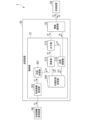
- FIG. 1 is a diagram for explaining an example of a device configuration of a communication system according to a first embodiment
- FIG. FIG. 2 is a diagram for explaining an example of information communication of the communication system according to the first embodiment
- FIG. 3 is a block diagram showing an example of a functional configuration of a transmission device according to the first embodiment
- FIG. FIG. 4 is a diagram for explaining a series of operations of the transmission device according to the first embodiment
- FIG. FIG. 4 is a diagram for explaining search and utilization of communication parameters according to the first embodiment
- 4 is a timing chart showing an example of timing of data transmitted by the transmission device according to the first embodiment
- 4 is a diagram for explaining communication history information according to the first embodiment
- FIG. 10 is a diagram for explaining an example of the configuration of a communication system according to a second embodiment
- FIG. FIG. 11 is a block diagram showing an example of a functional configuration of a transmission device according to a second embodiment
- FIG. FIG. 12 is a block diagram showing a first modification of the functional configuration of the transmission device according to the second embodiment
- FIG. 11 is a block diagram showing a second modified example of the functional configuration of the transmission device according to the second embodiment
- FIG. 11 is a diagram for explaining inheritance between transmitting apparatuses according to the second embodiment
- FIG. 12 is a diagram for explaining an example of a configuration of a communication system according to a third embodiment
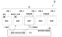
- FIG. FIG. 11 is a diagram for explaining inheritance in the case of relaying the relay device according to the third embodiment
- FIG. 12 is a diagram for explaining proxy inheritance when relaying the relay device according to the third embodiment
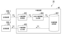
- FIG. 11 is a block diagram showing an example of a functional configuration of a relay device according to a third embodiment
- FIG. 12 is a block diagram showing a modification of the functional configuration of the relay device according to the third embodiment
- FIG. 11 is a block diagram showing an example of a functional configuration of a relay device according to a third embodiment
- FIG. 12 is a block diagram showing a modification of the functional configuration of the relay device according to the third embodiment
- FIG. 1 is a diagram for explaining an example of the device configuration of a communication system according to the first embodiment.
- the communication system 1 will be described with reference to the figure.
- a communication system 1 includes a transmitting device 20 and a receiving device 30 .
- the transmitting device 20 and the receiving device 30 perform information communication with each other.
- the communication system 1 may include multiple transmitters 20 and multiple receivers 30 .
- each transmitting device 20 communicates information with one or more receiving devices 30 .
- a case in which one transmission device 20 and a plurality of reception devices 30 are provided as an example of the communication system 1 will be described with reference to FIG. Specifically, as an example of the receiving device 30, a case of including a receiving device 30-1, a receiving device 30-2, and a receiving device 30-3 will be described.
- the transmitting device 20 and the receiving device 30 perform information communication with each other by short-range wireless communication.
- the transmitting device 20 and the receiving device 30 are wireless communication conforming to the Bluetooth (registered trademark) standard, particularly conforming to the BLE (Bluetooth Low Energy) standard, as an example of short-range wireless communication.
- BLE Bluetooth Low Energy
- An example in which information communication is performed by wireless communication will be described.
- the short-range wireless communication in this embodiment is not limited to an example of BLE, and various communication schemes can be adopted.
- near field communication may be NFC (Near Field Communication), Wi-Fi (registered trademark), IrDA (Infrared Data Association), TransferJet (registered trademark), ZigBee (registered trademark), and the like.
- wireless communication is not limited to short-distance communication, and may be LPWA (Low Power Wide Area) or the like.
- the transmitting device 20 may be the peripheral and the receiving device 30 may be the central.
- the transmitting device 20 as a peripheral transmits the transmission information IS without specifying the receiving device 30 .
- the receiving device 30 located near the transmitting device 20 transmits the receiving information IR when receiving the transmitting information IS.
- Information communication performed between the transmitting device 20 and the receiving device 30 may be a communication method in which a plurality of communication channels are defined within a predetermined frequency band.
- the transmitting device 20 and the receiving device 30 may exchange information using an advertisement packet in wireless communication conforming to the BLE standard.
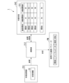
- FIG. 2 is a diagram for explaining an example of information communication in the communication system according to the first embodiment.
- An example of information communication performed between the transmitting device 20 and the receiving device 30 included in the communication system 1 will be described with reference to FIG.
- the transmitting device 20 transmits the transmission information IS based on the communication parameters calculated by the algorithm 231.
- the communication parameters may include, for example, a frequency band used for communication, a signal transmission interval or number of transmissions, transmission power, or the like.
- the transmission device 20 includes a control section 21 and a wireless communication section 22 .
- the wireless communication unit 22 controls radio waves transmitted from the antenna 221 based on communication parameters acquired from the control unit 21 . Also, the wireless communication unit 22 outputs information based on radio waves received by the antenna 221 to the control unit 21 .
- the control unit 21 has an algorithm 231 and calculates communication parameters.
- the control unit 21 is provided with an algorithm 231 to calculate communication parameters based on the communication history information 233 .
- the control unit 21 updates the calculated communication parameters as the guideline information 232 as needed.
- the control unit 21 outputs the calculated communication parameters to the wireless communication unit 22 . Further, the control unit 21 acquires information on radio waves received by the antenna 221 from the wireless communication unit 22 .
- the control unit 21 updates the guideline information 232 based on the deterioration rate included in the acquired radio wave information.
- the deterioration rate is a value indicating the degree of deterioration of communication quality, and may be calculated based on whether or not the transmission information IS transmitted by the transmitting device 20 reaches any of the receiving devices 30, for example. That is, the deterioration rate may be a value indicating whether or not communication between the transmitting device 20 and the receiving device 30 is successful. In this case, the deterioration rate may be binary. When the deterioration rate is binary, the control unit 21 calculates it using a control signal (for example, an ACK signal) or the like returned when the receiving device 30 correctly receives the transmission information IS.
- a control signal for example, an ACK signal
- the presence or absence of a scan response request to the BLE advertisement packet may be used as the degradation rate, or the presence or absence of a connection request from the central (that is, the receiving device 30) may be used as the degradation rate. good too.
- the reception device 30 may inform whether or not the transmission information IS has been correctly received using a different communication means without using wireless communication.
- the control unit 21 sets the deterioration rate low when the receiving device 30 correctly receives the transmission information IS.
- the control unit 21 may set the deterioration rate to 0 (zero) when the receiving device 30 correctly receives the transmission information IS.
- the deterioration rate may be based on information regarding the intensity of radio waves included in the radio waves received by the antenna 221 from the receiving device 30 .
- the information about the radio wave intensity may be, for example, RSSI (Received Signal Strength Indicator).
- the receiving device 30 includes a radio wave intensity measuring unit (not shown) and measures the radio wave intensity when the transmission information IS is received.
- the receiving device 30 transmits the measured radio wave intensity to the transmitting device 20 as reception information IR.
- the control unit 21 sets the deterioration rate to be higher as the radio wave intensity included in the received reception information IR is lower. That is, the smaller the deterioration rate, the less the radio waves transmitted to the receiving device 30 are deteriorated.
- the deterioration rate may be calculated from the error rate when the receiving device 30 receives information encoded with an error detection code or an error correction code.
- the control unit 31 included in the receiving device 30 calculates the error rate of the transmission information IS acquired from the transmitting device 20 .
- the receiving device 30 transmits the calculated error rate to the transmitting device 20 as reception information IR.
- the control unit 21 provided in the transmission device 20 sets the deterioration rate to be higher as the error rate included in the received reception information IR is higher.
- the signal transmitted to the receiving device 30 based on the output communication parameter is encoded by an encoding method having an error detection function, and the deterioration rate is obtained by decoding the signal received from the receiving device 30. Based on actual error rate.
- the receiving device 30 includes a control section 31 and a wireless communication section 32 .
- the wireless communication unit 32 receives radio waves from the transmitting device 20 via the antenna 321 .
- the control unit 31 calculates the radio wave intensity (RSSI) of the received radio wave, the error rate, etc., based on the received radio wave information input from the wireless communication unit 32 .
- the wireless communication unit 32 outputs the radio wave intensity, error rate, etc. calculated by the control unit 31 as reception information IR.
- the transmitting device 20 and the receiving device 30 may have the same device configuration. That is, in the communication system 1 , a device that acts as a transmitter at a certain point in time is called a transmitter 20 , and a device that receives radio waves transmitted by the transmitter 20 is called a receiver 30 . In the following description, when the transmitting device 20 and the receiving device 30 are not distinguished, they are also referred to as the communication device 10 .
- FIG. 3 is a block diagram illustrating an example of the functional configuration of the transmission device according to the first embodiment; An example of the functional configuration of the transmission device 20 will be described with reference to the same drawing. Configurations that have already been described in the description of the communication system 1 may be omitted by assigning the same reference numerals.
- the transmission device 20 includes a control section 21 and a wireless communication section 22 .
- the transmission device 20 includes a CPU (Central Processing Unit) (not shown) connected by a bus, a storage device such as a ROM (Read only memory) or a RAM (Random access memory), and executes a transmission program to control a control unit. 21 and a wireless communication unit 22 .
- Control unit 21 includes internal state storage unit 242 , calculation unit 212 , output unit 213 , storage control unit 215 , state storage unit 251 , and state information acquisition unit 252 .
- All or part of each function of the transmission device 20 may be realized using hardware such as ASIC (Application Specific Integrated Circuit), PLD (Programmable Logic Device), or FPGA (Field-Programmable Gate Array).
- the transmission program may be recorded on a computer-readable recording medium.
- Computer-readable recording media include portable media such as flexible disks, magneto-optical disks, ROMs and CD-ROMs, and storage devices such as hard disks incorporated in computer systems.
- a transmission program may be transmitted via an electric communication line.
- State storage unit 251 stores state information IC.
- the state information IC is information obtained at a specific moment, among information that changes according to at least one of the position of the device itself and the time.
- the state information IC may be, for example, time information indicating time, position information indicating the position of the device itself, environmental information around the device itself, and the like.
- the position information indicating the position of the device may be position information indicating the position of the device in a three-dimensional space, or position information indicating the position of the device in two-dimensional coordinate information. good too. Two-dimensional coordinate information does not require height (altitude) information.
- the state storage unit 251 may store the current time measured by a clock unit (not shown) included in the transmission device 20 .
- the time information may be updated by the timer.
- the state information IC is location information, it may be, for example, location coordinates obtained using a positioning system.
- the position coordinates are acquired by a GPS (Global Positioning System) communication unit (not shown) provided in the transmitting device 20 .
- the GPS communication unit receives radio waves from satellites such as GPS.
- the position of the device itself is measured from the received radio waves.
- the state storage unit 251 stores environmental information such as temperature, humidity, illuminance, UV (ultraviolet rays), air pressure, noise, and acceleration.
- the state information IC is obtained from environmental sensors (environmental information acquisition department).
- the clock unit, GPS communication unit, and environment sensor may be provided outside the transmission device 20 .
- the transmission device 20 acquires the state information IC from an externally provided timer, GPS communication unit, and environment sensor.
- the location information may be estimated based on the information of the connected access point. Also, the location information may be estimated based on the location information of the access point and the distance information from the access point to the device itself. That is, the position information may be estimated based on radio waves for obtaining the state information IC. Also, the position information may be estimated based on radio waves for information communication that are different from radio waves for acquiring the state information IC. That is, the position information may be estimated based on both or one of the radio waves for obtaining the status information IC and the radio waves for information communication.
- the state information acquisition device 50 is also used when the devices for acquiring the state information IC such as the timekeeping unit, the GPS communication unit, and the environment information acquisition unit are not distinguished.
- the state information acquisition unit 252 may acquire the state information IC from the state information acquisition device 50 .
- the state storage unit 251 may store a plurality of pieces of state information IC acquired at a plurality of moments. That is, the state storage unit 251 may store the history of the state information IC.
- the internal state storage unit 242 stores internal state information ISI.
- the internal state information ISI is information in which state information IC is associated with information used for calculation of the communication parameter PM used when the transmitting device 20 performs information communication.
- the information used to calculate the communication parameter PM may be, for example, a learned parameter learned by a machine learning algorithm, or an action value function used by a reinforcement learning algorithm.
- the internal state storage unit 242 may function as the communication history information storage unit 211 that stores the communication history information IH.
- the communication history information IH is an example of the internal state information ISI.
- the communication history information IH is information in which a communication parameter PM for performing information communication and a deterioration rate D when information communication is performed using the communication parameter PM are associated with each other.
- the deterioration rate D is a value based on radio waves transmitted using the communication parameter PM when transmitting information to the receiving device 30 and radio waves received from the receiving device 30 .
- the communication history information storage unit 211 may include a volatile RAM (Random Access Memory) or a nonvolatile ROM (Read Only Memory).
- the computation unit 212 computes the communication parameter PM based on the state information IC stored in the state storage unit 251 and the internal state information ISI stored in the internal state storage unit 242 .
- the calculation unit 212 determines the communication parameter PM based on the accumulated plurality of state information ICs.
- the state information IC is information indicating time
- information corresponding to the time indicated in the state information IC is obtained from the internal state storage unit 242, and the communication parameter PM is calculated based on the obtained information. That is, the calculation unit 212 calculates the communication parameter PM based on the information stored in the internal state storage unit 242 and corresponding to the time indicated by the state information IC stored in the state storage unit 251 .
- the calculation unit 212 calculates the communication parameter PM based on the information stored in the internal state storage unit 242 and corresponding to the environmental information indicated by the state information IC stored in the state storage unit 251. .
- the state information IC is information indicating the position information of the device itself
- information corresponding to the position information indicated by the state information IC is acquired from the internal state storage unit 242, and communication parameters are calculated based on the acquired information.
- Calculate PM That is, the calculation unit 212 calculates the communication parameter PM based on the information stored in the internal state storage unit 242 and corresponding to the position information indicated by the state information IC stored in the state storage unit 251. .
- the state information IC may be image information in which the surroundings of the device are captured, or audio information collected and recorded in the surroundings of the device.
- the state information acquisition unit 252 acquires image information or audio information from a camera or microphone (not shown).
- the calculation unit 212 performs estimation based on the acquired image information, and calculates the communication parameter PM based on the estimated result.
- the computation unit 212 performs estimation based on the acquired voice information, and computes the communication parameter PM based on the estimated result.
- the computing unit 212 may estimate the radio wave congestion state from the state information IC and compute the communication parameter PM based on the estimated congestion state. That is, the calculation unit 212 estimates the radio wave congestion state around the device from the state information IC stored in the state storage unit 251, and calculates the communication parameter IC based on the estimated congestion state IC.
- the calculation unit 212 may estimate the density of people instead of the radio wave congestion.
- the computing unit 212 estimates the density of people around the device from the state information IC stored in the state storage unit 251, and computes the communication parameter PM based on the estimated density of people.
- the state information IC may be information indicating the weather around the device itself.
- the calculation unit 212 acquires information corresponding to the information indicating the weather indicated by the state information IC from the internal state storage unit 242, and stores the information in the acquired information.
- the communication parameter PM is calculated based on this. That is, the calculation unit 212 calculates the communication parameter PM based on the information stored in the internal state storage unit 242 and corresponding to the information indicating the weather indicated in the state information stored in the state storage unit 251.
- the weather information includes weather information such as temperature, humidity, visibility, wind, amount of clouds, rain, snow, and thunder, and is acquired by various sensors (not shown). Alternatively, it may be acquired from the outside by some communication method.
- the computing unit 212 computes the communication parameter PM using a machine learning algorithm.
- the machine learning algorithm may be, for example, a reinforcement learning algorithm that uses state information, such as Q-learning, deep reinforcement learning, or the like.
- the machine learning algorithm is a reinforcement learning algorithm
- the machine learning algorithm uses a value calculated from the deterioration rate D as a reward and learns the communication parameter PM for maximizing the reward. It is preferable that the higher the deterioration rate D, the smaller the reward.
- the machine learning algorithm may be a pre-learned model. Note that the machine learning algorithm may not be learned at the time of the first operation. Therefore, if the machine learning algorithm is untrained, the results may be determined by random numbers.
- a machine learning algorithm is learned based on the communication history information IH.
- the communication history information IH is information in which the communication parameter PM output by the output unit 213 is associated with the deterioration rate D obtained as a result of information communication using the communication parameter PM. That is, the calculation unit 212 learns based on the deterioration rate D obtained as a result of information communication using the communication parameter PM output from the output unit 213 .
- the internal state storage unit 242 may store a plurality of pieces of internal state information ISI.
- the calculation unit 212 calculates the communication parameter PM based on the internal state information ISI corresponding to the state information IC stored in the state storage unit 251 among the plurality of stored internal state information ISI.
- the calculation unit 212 outputs parameter information IP including the calculated communication parameter PM to the output unit 213 .
- the output unit 213 outputs parameter information IP including the communication parameter PM calculated by the calculation unit 212 to the wireless communication unit 22 .
- the wireless communication unit 22 performs information communication with the receiving device 30 based on the communication parameter PM included in the parameter information IP output by the output unit 213 .
- the storage control unit 215 acquires the deterioration information ID including the deterioration rate D from the wireless communication unit 22.
- the storage control unit 215 associates the acquired deterioration information ID with the communication parameter PM and stores it in the communication history information storage unit 211 as the communication history information IH.
- the storage control unit 215 obtains the parameter information IP from at least one of the output unit 213 and the wireless communication unit 22, and stores the communication history by associating the communication parameter PM and the deterioration rate D included in the obtained parameter information IP.
- Information IH is generated, and the generated communication history information IH is stored in the communication history information storage unit 211 .
- FIG. 4 is a diagram for explaining a series of operations of the transmission device according to the first embodiment. An example of the operation of the transmission device 20 will be described with reference to the figure.
- Calculation unit 212 refers to state information IC stored in state storage unit 251 and internal state information ISI stored in internal state storage unit 242 to determine communication parameter PM.
- the internal state information ISI is information in which "communication environment”, "value function A”, and “value function B” are associated with each other.
- “Communication environment” is information corresponding to the type of state information IC.
- the state information IC is time information
- the "communication environment” is information about time.
- the state information IC is positional information
- the "communication environment” is positional information.
- the state information IC is environment information
- the "communication environment” is information about the environment.
- Both “value function A” and “value function B” may be action value functions in reinforcement learning.
- environment 1 is associated with “communication environment”
- A1 is associated with “value function A”
- B1 is associated with “value function B”
- A2 is associated with B2 as “value function B”
- environment 3 is associated with “communication environment”
- A3 is associated with “value function A”
- B3 is associated with “value function B”
- environment 4 is associated with "communication environment”.
- A4 is associated as "value function A”
- B4 is associated as "value function B”
- An is “value function A”
- Bn as "value function B” (n is a natural number equal to or greater than 1).
- the calculation unit 212 acquires the state information IC from the state storage unit 251, selects a value function according to the communication environment based on the state information IC and the internal state information ISI, and performs communication based on the selected value function.
- Communication parameters PM include, for example, communication channel and communication strength. In one example shown in FIG. 4, a value function corresponding to the environment 2 is selected, and the communication channel and communication strength are determined based on the selected value function. Specifically, channel 37 and channel 38 are determined as the communication channels, and -8 [dBm] is determined as the communication strength.
- the calculation unit 212 updates the internal state information ISI stored in the internal state storage unit 242 according to the parameters used for communication and the communication result. In this way, the calculation unit 212 repeats “search”, which is an operation of learning suitable communication parameters, and “utilization”, which is an operation of performing communication using the communication parameters PM determined in the search, while performing information communication.
- search which is an operation of learning suitable communication parameters
- utilization which is an operation of performing communication using the communication parameters PM determined in the search
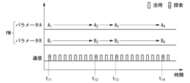
- FIG. 5 is a diagram for explaining search and utilization of communication parameters according to the first embodiment.
- the "search” and “utilization” of the algorithm 231 will be described with reference to FIG.
- Algorithm 231 is an example of computing unit 212 .
- “Parameter A” and “Parameter B” are examples of communication parameters PM. That is, in one example described with reference to the figure, the communication parameter PM has two parameters. The time change of each parameter is shown with time on the horizontal axis.
- Communication indicates whether the algorithm 231 is “searching” or “exploiting” with time on the horizontal axis.
- Search is indicated by a black rectangle
- “utilization” is indicated by a white rectangle.
- algorithm 231 performs a "search.” Algorithm 231 determines the value of parameter A to be "A1" and the value of parameter B to be “B1". From time t11 to time t12 , the transmitting device 20 performs information communication using the determined communication parameter PM. That is, from time t11 to time t12 , "utilization” is performed. At time t- 12 , the algorithm 231 "searches" for more suitable communication parameters PM based on the accumulated communication history information IH as a result of being "utilized” from time t- 11 to time t- 12 .
- algorithm 231 determines the value of parameter A from “A1” to “A2” and the value of parameter B from “B1" to “B2". From time t12 to time t13 , the transmitting device 20 performs information communication using the determined communication parameter PM.
- the algorithm 231 determines a more suitable communication parameter PM based on the accumulated communication history information IH as a result of being "utilized” from time t11 to time t12 and from time t12 to time t13 . "Explore. As a result of the search, algorithm 231 determines the value of parameter A from “A2" to "A3" and the value of parameter B from "B2" to "B3". From time t13 to time t14 , the transmitting device 20 performs information communication using the determined communication parameter PM.
- the algorithm 231 repeats "searching” and "utilization” to derive suitable communication parameters PM, and performs information communication based on the derived communication parameters PM.
- time t 11 , time t 12 , time t 13 , and time t 14 which are timings for “searching”, are predetermined timings determined by the algorithm 231 .
- the timing of "searching” may be irregular as in this example, or may be regular timing.
- Algorithm 231 is specifically a machine learning algorithm. More specifically, the algorithm 231 may be a MAB (Multi Armed Bandit) algorithm or the like. That is, the calculation unit 212 may be trained using the MAB algorithm (multi-armed bandit algorithm). By using the MAB algorithm, the transmitting device 20 can reliably transmit information to the receiving device 30 with low power consumption.
- MAB Multi Armed Bandit
- the MAB algorithm is an algorithm used to solve the problem of maximizing the reward in a limited number of trials when there are multiple slot machines with unclear reward probabilities.
- the amount of reward is set in consideration of the trade-off between the power consumption required for transmission and whether or not the receiving device 30 has correctly received the information. There must be.
- the transmission device 20 acquires the amount of power required for communication by a predetermined method.
- the transmitting device 20 may measure the amount of power actually consumed, for example, by including a power measuring device (not shown). Further, the transmission device 20 stores a power consumption correspondence table (not shown) in which the communication parameter PM and the estimated power consumption are associated with each other, and obtains the power consumption by referring to the power consumption correspondence table. good too.
- algorithm 231 which is the MAB algorithm, will determine the communication parameter PM to reduce power consumption, which can limit the amount of power required for transmission. Since the lower the deterioration rate D, the higher the quality (that is, the more reliable) the information has been transmitted, the lower the deterioration rate D, the more the reward amount is preferably increased.
- Algorithm 231 uses the calculated deterioration rate D to configure communication history information IH.
- the communication history information IH may be time-series data of the deterioration rate D.
- FIG. Algorithm 231 determines a suitable communication parameter PM based on communication history information IH, which is time-series data of deterioration rate D.
- the communication history information IH may be a single value calculated based on the deterioration rate D accumulated in the past.
- the communication history information IH may be acquired from another device.
- the other device may be the receiving device 30, for example. That is, in another example, receiving device 30 holds communication history information IH instead of transmitting device 20 .
- the receiving device 30 may count the number of times that information has been successfully received from the transmitting device 20 and estimate the deterioration rate based on the counted number of times. In this case, the receiving device 30 transmits the communication history information IH to the transmitting device 20 at a predetermined timing.
- the algorithm 231 can select one from all possible combinations of the communication parameter PM. can. That is, the algorithm 231 calculates the communication parameter PM by selecting one combination from among the combinations of the constituent elements included in the communication parameter PM. Specifically, a case in which the communication parameter PM has components x, components y, and components z will be described.
- the communication parameter PM can be determined by selecting one from (3 ⁇ 2 ⁇ 3) combinations. By configuring in this way, the algorithm 231 can easily optimally select the communication parameter PM composed of multiple elements.
- the algorithm 231 can use the UCB (Upper Confidence Bound) 1 algorithm when the combination of communication parameters PM is somewhat complicated.
- the calculator 212 is trained using the UCB1 algorithm.
- the algorithm 231 can use a lighter TOW (Tug Of War) algorithm when it is necessary to operate on a low-spec microcomputer.
- the calculator 212 is trained using the TOW algorithm.
- the UCB1 algorithm here includes the UCB1 algorithm and the UCB1-tuned algorithm.
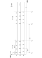
- FIG. 6 is a timing chart showing an example of timing of data transmitted by the transmission device according to the embodiment.
- the communication parameter PM has "communication channel”, “first transmission interval SI1", “second transmission interval SI2", “transmission number ST”, and “transmission power” as its components.
- three advertising channels, 37ch (2402 MHz), 38ch (2426 MHz), and 39ch (2480 MHz), which are advertising channels used for BLE advertising, are used as "communication channels”.
- the horizontal axis represents the temporal change of the data transmitted to each channel.
- the wireless communication unit 22 sequentially outputs data A to each of 37ch, 38ch and 39ch.
- a period T21 indicates a period required for data A to be sent. Specifically, the wireless communication unit 22 outputs data A to 37ch at time t21 , then outputs data A to 38ch, and then outputs data A to 39ch. After outputting the data A to each channel, the wireless communication unit 22 outputs the data A to each channel again after a first transmission interval SI1. This is repeated until a predetermined number of transmissions ST is reached. According to the example shown in FIG. 7, the number of transmissions ST is 4, so the same data is output four times for each channel. That is, the communication parameter PM includes the first transmission interval SI1, and the wireless communication unit 22 transmits the signal to the receiving device 30 based on the first transmission interval SI1.
- the first transmission interval SI1 is an interval for transmitting the same data to each channel.
- an advertisement process is a process that is performed for each of a plurality of advertising channels, and is performed separately for three advertising channels, 37, 38, and 39 channels, for example.
- each channel may interfere with other radio waves existing in space. If interference occurs in all three channels, or if the receiving device 30 is not ready for reception, the information transmitted by the transmitting device 20 may not reach the receiving device 30 . In preparation for such a situation, a packet in which the same data is encoded is periodically transmitted a plurality of times. Note that the case where the receiving apparatus is not ready for reception is, for example, the case where the BLE receiving side (central) performs the receiving operation intermittently in order to reduce power consumption.
- the wireless communication unit 22 starts outputting data B different from data A after the second transmission interval SI2 has elapsed since the start of outputting data A at time t21 . That is, from time t23 to time t24 , the wireless communication unit 22 outputs data B to 37ch, 38ch, and 39ch.
- the second transmission interval SI2 is the interval until data is updated and newly transmitted.
- the wireless communication unit 22 completes the information transmission processing to the receiving device 30 during the transmission time, which is the time from the start of signal generation to the end of transmission.
- the calculation unit 212 may adjust the communication parameter PM so as to reduce the transmission time when the receiving device 30 continuously and stably receives the information transmitted by the wireless communication unit 22 .
- the calculation unit 212 may adjust the communication parameter PM based on information included in the reception information IR received from the reception device 30 so as to reduce the transmission time.
- the case where the receiving device 30 continuously and stably receives the information transmitted by the wireless communication unit 22 may be determined by the receiving device 30 or may be determined by the transmitting device 20 .
- the determination may be made by the transmitting device 20, the determination may be made based on whether or not there is reception information IR as a response to the transmission information IS.
- the wireless communication unit 22 repeatedly performs transmission processing from the time the system is started until the expected operating life.
- the system is, for example, a system that operates the transmitting device 20, and the time when the system is activated may be when the power of the transmitting device 20 is turned on.
- the transmitter 20 When the transmitter 20 is powered on, it may be the first power on before shipment from the factory or the first power on after the shipment from the factory.
- the calculation unit 212 sets the communication parameter PM so as to reduce the total time required for the information transmission process when the receiving device 30 continuously and stably receives the information transmitted by the wireless communication unit 22. adjust.
- the calculation unit 212 may adjust the communication parameter PM based on information included in the reception information IR received from the reception device 30 so as to reduce the total time required for information transmission processing.
- the radio communication unit 22 transmits the first data (data A) encoded with the same data based on the first transmission interval SI1 until the number of times of transmission ST reaches a specific number of transmissions ST.
- a different second data (data B) is transmitted based on the second transmission interval SI2.
- the communication parameter PM includes the second transmission interval SI2 and the number of transmissions ST.
- the calculation unit 212 adjusts the communication parameter PM so as to decrease the number of times of transmission ST when the receiving device 30 continuously and stably receives the information sent by the wireless communication unit 22 .
- the calculation section 212 may adjust the communication parameter PM so as to decrease the number of transmissions ST based on information included in the reception information IR received from the reception device 30 .
- the second transmission interval SI2 When the second transmission interval SI2 is included in the communication parameter PM, the second transmission interval SI2 is increased when the receiving device 30 continuously and stably receives the information transmitted by the wireless communication unit 22. , the communication parameter PM may be adjusted. Further, when the information transmitted by the wireless communication unit 22 is not continuously received by the receiving device 30, the calculation unit 212 may adjust the communication parameter PM so as to increase the second transmission interval SI2. good. Also, when the communication environment improves and data can be received stably, the second transmission interval SI2 may be decreased or restored to its original value. By decreasing the second transmission interval SI2 or returning it to the original value, the time until connection with the receiving device 30 can be shortened, and stable connection can be achieved. Also, the second transmission interval SI2 may be reduced when transmitting data with high urgency. As a result, it is possible to suppress power consumption when transmitting normal data, and to transmit data with high urgency to the receiving device 30 without delay.
- a channel mask is a communication parameter for determining a channel to be used when using a communication method in which a plurality of channels are defined within a use band.
- the communication parameter PM may include a channel mask for determining the channel to be used.
- the channels specified by the channel mask may be channels that are not used for communication.
- the communication channel may be an advertising channel defined by the BLE standard. Advertising may be connectable advertising.
- the deterioration rate D may be a value calculated based on whether or not a connection request has been answered.
- the calculation unit 212 determines the communication parameter PM so that the deterioration rate D decreases when communication is performed with the receiving device 30 of a specific partner via the channel mask included in the calculated communication parameter PM.
- the BLE advertising process is performed separately for the three advertising channels 37, 38, and 39 channels.
- the advertising process is performed by the 37th channel and the 39th channel, and if the 38th channel and the 39th channel are masked, the advertising process is performed by the 37th channel.
- the less channels are used the less the power required for transmission can be naturally reduced, but on the other hand, there is a trade-off relationship that the probability that information cannot be transmitted due to interference increases.
- the number of channels to be used should be minimized by channel masking, and should be limited to channels with the lowest probability of interference. Also, if the environment in which the transmitting device 20 is placed is a communication environment with a lot of interference, more channels should be used even if power consumption is sacrificed.
- the transmission device 20 cannot know the situation of the communication environment in advance, it adapts to the existing communication environment by "utilizing" and “searching" the channel mask, and transmits information with low power consumption. A channel mask can be selected.
- the algorithm 231 considers the trade-off between reliable transmission of information and power consumption and appropriately updates the channel mask.
- advertising may accept scan requests.
- the central receiving the advertising packet can send a scan request, and the degradation rate D is calculated based on whether the scan request is answered.
- the deterioration rate D may be calculated based on the number of advertising packets received by a specific one or a plurality of receiving devices 30.
- the first transmission interval SI1 is a time interval for transmitting the same data. This reduces the probability of interference by distributing (redundant) the transmission of information over time. However, it is not realistic to simply define the procedure for the deterioration rate, and for example, it is desirable to lengthen the time interval when continuous interference occurs over a relatively long period of time. On the other hand, it is desirable to shorten the time interval when interference occurs frequently in bursts (in a form condensed into a short period of time). Since it is difficult to estimate the time-dependent degree of interference in such a communication environment in advance, the transmitting device 20 uses "exploitation” and "search” to derive a suitable communication parameter PM.
- the algorithm 231 adjusts these values independently.
- the calculation unit 212 may adjust the communication parameter PM so as to decrease the first transmission interval SI1 when the receiving device 30 continuously and stably receives the information transmitted by the wireless communication unit 22. good.
- the second transmission interval SI2 is an interval for newly transmitting updated information. For example, when information is not updated frequently, it is desirable to increase the second transmission interval SI2 when the deterioration rate D can be considered sufficiently small.
- the second transmission interval SI2 also affects the power consumption during the period from start to finish of operation of the device.
- the number of channels and the transmission power should be maintained as they are in case the receiving apparatus 30, which is the other party of communication, recovers, but the frequency of presence confirmation should be reduced.
- the time elements (first transmission interval SI1, number of transmissions ST and second transmission interval SI2) as described above do not necessarily have to be used with values that exactly match the values determined by algorithm 231 .
- the numerical value determined by the algorithm 231 may be given some width and used as the communication interval. That is, the first transmission interval SI1, the number of transmissions ST, and the second transmission interval SI2 may be time intervals based on random values.
- a time interval based on a random value may be realized by adding or subtracting a random value to or from the determined numerical value.
- the method of using time intervals based on random values is useful for preventing interference due to matching intervals when multiple devices use the technique of the communication system 1 .
- interference may continue because the timings match. Even in such a case, interference can be avoided by determining the time interval based on a random value.
- the components of the transmitting device 20 have been described as the communication parameters PM, the components of the receiving device 30 may be used as the communication parameters.
- the components of the receiving device 30 may be, for example, the ON duty ratio of the communication section of the receiving device 30, the number of stages of the multi-stage amplifier, the response speed of responses to received packets, and the like.
- FIG. 7 is a diagram showing a modification of communication history information according to the embodiment.
- the communication history information IHA will be described with reference to FIG.
- the communication history information IHA is a modification of the communication history information IH. Configurations similar to those of the communication history information IH may be denoted by similar reference numerals, and description thereof may be omitted.
- the communication history information IHA further has a parameter identifier PMID, and includes a channel mask CM, first transmission interval SI1, number of transmissions ST, second transmission interval SI2, and power consumption PC as communication parameters PM. It differs from the communication history information IH in that it has
- the communication history information IHA is stored in the communication history information storage unit 211, and the calculation unit 212 calculates the communication parameter PM based on the communication history information IHA stored in the communication history information storage unit 211.
- the power consumption PC is power consumption generated by transmitting radio waves using the communication parameter PM included in the communication history information IHA.
- the communication history information IHA is associated with the deterioration rate D when the communication parameter PM is used. That is, the calculation unit 212 calculates the communication parameter PM based on the power consumption PC generated by transmitting radio waves using the communication parameter PM included in the communication history information IHA and the corresponding deterioration rate D. More specifically, the computing unit 212 computes the communication parameter PM so as to reduce the power consumption PC.
- the communication history information IHA has, as communication parameters PM, a channel mask CM, a first transmission interval SI1, the number of times of transmission ST, a second transmission interval SI2, and power consumption PC. It is possible to perform communication using a suitable communication parameter PM with higher accuracy, taking into account the trade-off between communication reliability and power consumption.
- the communication history information IHA has the parameter identifier PMID, all combinations of possible values for each communication parameter PM can be examined without omission. Also, since the communication history information IHA has the parameter identifier PMID, the algorithm 231 can easily find suitable parameters.
- the transmission device 20 includes the state storage unit 251 to store the state information IC, the internal state storage unit 242 to store the internal state information ISI, and the calculation unit 212.
- the communication parameter PM is calculated based on the state information IC and the internal state information ISI by being provided, and the communication parameter PM calculated by being provided with the output unit 213 is output. Therefore, according to this embodiment, since the communication parameter PM is determined based on the state information IC, it is possible to quickly adapt to the communication environment.
- the computing unit 212 includes a machine learning algorithm, and the internal state information ISI includes learned parameters learned by the machine learning algorithm. Therefore, according to this embodiment, by using machine learning, it is possible to determine a suitable communication parameter PM based on a plurality of input variables (communication results, a plurality of state information).
- the machine learning algorithm is a reinforcement learning algorithm
- the internal state information ISI includes an action-value function used by the reinforcement learning algorithm. Therefore, according to the present embodiment, it is possible to repeat the search and utilization by itself and quickly determine the communication parameter PM adapted to the environment.
- the state storage unit 251 stores a plurality of state information ICs acquired at a plurality of instants, and the calculation unit 212 calculates the communication parameters based on the plurality of accumulated state information ICs. Determine PM. Therefore, according to this embodiment, not only the current state but also the past state can be stored and utilized. Therefore, according to this embodiment, a more suitable communication parameter PM can be determined.
- the transmission device 20 further includes the state information acquisition unit 252 for acquiring state information. Therefore, according to the present embodiment, the transmission device 20 can acquire information from sensors provided inside or outside the device itself.
- the state information IC is information indicating time.
- the communication status may change depending on the time zone.
- the communication conditions may be poor during the daytime hours when many people use radio waves, and the communication conditions may be good during nighttime hours when many people do not use radio waves.
- the transmitting device 20 can adapt to a communication environment in which communication conditions fluctuate depending on the time of day.
- the state information IC is information indicating environmental information.
- the communication situation may change depending on the surrounding environment.
- the number of people using radio waves may differ between rainy days and sunny days.
- the transmission device 20 can adapt to a communication environment in which the communication status varies depending on the surrounding environment.
- the state information IC is information indicating the position information of the own device.
- the communication status may change depending on the position of the own device.
- the number of people using radio waves may differ between urban and rural areas.
- the transmission device 20 can adapt to a communication environment in which the communication status varies depending on the position of the device itself.
- the positional information is not limited to absolute positional information, and includes relative positional information such as distance and positional relationship with the target object.
- the position information is position coordinates obtained using a positioning system. Therefore, according to this embodiment, the transmitting device 20 can acquire position information or coordinate information from an external positioning system.
- the position information is estimated based on both or either of the radio waves for acquiring the state information IC and the radio waves for information communication. Therefore, according to this embodiment, it is possible to acquire position information even in a building where GPS radio waves cannot be acquired. Further, according to this embodiment, in addition to position information estimated by GPS, position information is specified by radio waves, so position information can be estimated more easily and in more detail.
- the calculation unit 212 estimates the radio wave congestion situation around the own device from the state information IC stored in the state storage unit 251, and performs communication based on the estimated congestion situation. Compute the parameter PM. Therefore, according to the present embodiment, it is possible to estimate the degree of crosstalk in the communication environment in which the transmitting device 20 is placed, and quickly adapt to the communication environment in which the device itself is placed based on the estimated state of crosstalk. .
- the calculation unit 212 estimates the density of people around the device from the state information IC stored in the state storage unit 251, and communicates based on the estimated density of people. Compute the parameter PM. Therefore, according to the present embodiment, it is possible to estimate the radio wave congestion situation based on the density of surrounding people, and quickly adapt to the communication environment in which the device itself is located based on the estimated congestion situation. .
- the state information IC is image information obtained by imaging the surroundings of the device itself.
- the communication parameter PM is calculated based on this. Therefore, according to the present embodiment, by estimating the state of congestion based on the image acquired by the camera, the state of congestion is estimated from the number of people in the vicinity. According to this embodiment, it is possible to quickly adapt to the communication environment in which the device itself is placed based on the estimated degree of crosstalk.
- the state information IC is sound information collected around the device itself, and the calculation unit 212 performs estimation based on the sound information, and the estimated result A communication parameter PM is calculated based on. Therefore, according to the present embodiment, by estimating the state of congestion based on the voice information acquired by the microphone, it is possible to estimate the state of congestion with low-load processing, thereby reducing power consumption and miniaturizing the device. can do
- the state information IC is information indicating the weather around the own device
- the calculation unit 212 is information stored in the internal state storage unit 242
- Communication parameters are calculated based on information corresponding to the information indicating the weather indicated in the state information IC stored in section 251 . Therefore, according to this embodiment, even when the communication system 1 performs communication using a communication method that is affected by the weather, the transmission device 20 can adapt to the environment.
- the internal state storage unit 242 stores a plurality of pieces of internal state information ISI
- the calculation unit 212 stores the stored plurality of pieces of internal state information ISI in the state storage unit 251.
- Communication parameters are calculated based on the internal state information ISI corresponding to the stored state information IC. That is, the calculation unit 212 refers to the internal state information ISI corresponding to the state information IC and determines the communication parameter PM. Therefore, according to this embodiment, the state information IC can be easily utilized by simple processing.
- FIG. A communication system 1A in the second embodiment includes a plurality of transmitters 20A.
- the transmitting device 20A differs from the transmitting device 20 in that information communication is performed among a plurality of transmitting devices 20A.
- information communication between transmission devices 20A is also referred to as "inheritance”.
- 20 A of transmitter which concerns on 2nd Embodiment assume operating in the place where a stable external power supply does not exist. When operating in locations where a stable external power supply is not present, once the battery life expires, the transmitter 20A will not be able to continue its operation and will remain inoperable until the battery is recharged or replaced.
- the battery of the transmitter 20A may not be rechargeable and is disposable. If the battery of the transmitting device 20A is disposable, the transmitting device 20A is discarded when the battery life expires.
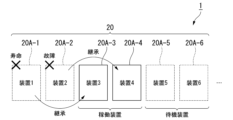
- the sensing information obtained by transmitter 20A is important, and inoperability can be a problem if it is undesirable to interrupt the transmission of data. In such a case, the transmitting device 20A takes over its function to another transmitting device 20A that is on standby in the vicinity of itself.
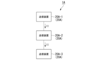
- FIG. 8 is a diagram for explaining an example of the configuration of a communication system according to the second embodiment. "Inheritance" in the second embodiment will be described with reference to FIG.
- the communication system 1A includes a transmission device 20A-1, a transmission device 20A-2, and a transmission device 20A-3.
- the transmitting device 20A-1 transmits inheritance information II to the transmitting device 20A-2.
- the transmitting device 20A-2 transmits inheritance information II to the transmitting device 20A-3. That is, the transmission device 20A-1 takes over to the transmission device 20A-2, and the transmission device 20A-2 takes over to the transmission device 20A-3.
- the inherited information II is, for example, information including the result of learning by the transmitting device 20A. That is, according to this embodiment, the information learned by the transmission device 20A-1 is inherited by the transmission device 20A-2. Therefore, according to the present embodiment, even if the transmission device 20A-1 becomes unusable due to product life or failure, the transmission device 20A-2 replaces the transmission device 20A-1, thereby learning Information can still be used. Similarly, even if the transmitter 20A-2 becomes unusable due to product life or failure, etc., the learned information can be continuously utilized by replacing the transmitter 20A-3 with the transmitter 20A-2. can be done.
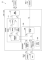
- FIG. 9 is a block diagram showing an example of the functional configuration of a transmission device according to the second embodiment.
- An example of the functional configuration of the transmission device 20A will be described with reference to this figure.
- the same reference numerals are given to the same configurations as those of the transmission device 20, and the description may be omitted.
- the transmitting device 20A differs from the transmitting device 20 in that it further includes an inheritance control section 240 .
- Inheritance control section 240 includes internal state acquisition section 241 and internal state output section 244 .
- the inheritance control unit 240 controls inheritance of the internal state information ISI between the transmitters 20A.
- the transmitting device 20A-1 inherits the internal state information ISI from the transmitting device 20A-2, and inherits the internal state information ISI to the transmitting device 20A-3.
- the transmission device 20A-2 is also referred to as the first device, and the transmission device 20A-3 as the second device.
- the internal state acquisition unit 241 acquires internal state information ISI indicating the internal state of the first device from the transmitting device (first device) 20A-2, which is a device separate from itself.
- the internal state acquisition unit 241 causes the internal state storage unit 242 to store the acquired internal state information ISI. That is, the internal state storage unit 242 stores the internal state information ISI acquired by the internal state acquisition unit 241 .
- a device separate from itself means an independent device that communicates with each other. Therefore, even separate bodies of the same standard are devices separate from themselves.
- the calculation unit 212 performs processing based on the internal state information ISI stored in the internal state storage unit 242.
- the process based on the internal state information ISI may be, for example, a process of calculating a communication parameter PM for information communication based on the internal state information ISI.
- the calculation unit 212 updates the internal state information ISI stored in the internal state storage unit 242 as a result of the processing. That is, the internal state information ISI stored in internal state storage unit 242 is updated based on the processing performed by arithmetic unit 212 .
- the internal state output unit 244 outputs the internal state information ISI stored in the internal state storage unit 242 at predetermined inheritance timing. Specifically, the internal state output unit 244 outputs to a transmission device (second device) 20A-3, which is a separate device from the transmission device (first device) 20A-2.
- some functions of the successor device may be in a dormant state.
- Some of the functions in the dormant state may be, for example, functions that are not related to inherited functions such as the computing unit 212 . That is, when the internal state acquisition unit 241 acquires the internal state information ISI, the calculation unit 212 is in the hibernation state, and the internal state acquisition unit 241 and the internal state output unit 244 are not in the hibernation state.
- FIG. 10 is a block diagram showing a first modification of the functional configuration of the transmission device according to the second embodiment.
- a first modification of the transmission device 20A will be described with reference to the same figure.
- a first modified example of the transmission device 20A is different from the above-described transmission device 20A in that the transmission device 20A includes a inheritance timing information acquisition unit 245.
- FIG. 10 shows a first modification of the functional configuration of the transmission device according to the second embodiment.
- a first modification of the transmission device 20A will be described with reference to the same figure.
- a first modified example of the transmission device 20A is different from the above-described transmission device 20A in that the transmission device 20A includes a inheritance timing information acquisition unit 245.
- the inheritance timing information acquisition unit 245 acquires inheritance timing information IT.
- the inheritance timing information IT includes information about the inheritance timing, which is the timing that triggers the inheritance.
- the internal state output unit 244 outputs the internal state information ISI based on the information about the inheritance timing included in the acquired inheritance timing information IT.
- the succession timing information acquisition unit 245 may acquire information about the remaining battery level of the battery 60 that drives the self device as the succession timing information IT.
- the information regarding the remaining battery level of the battery 60 may be the power supply voltage.
- the internal state output unit outputs internal state information ISI when the remaining battery level of the battery 60 included in the acquired inheritance timing information IT falls below a predetermined threshold. If the information about the remaining battery level of the battery 60 is the power supply voltage, the internal status output unit outputs the internal status information ISI when the power supply voltage is below a predetermined threshold.
- the transmission device 20A may inherit based on a predetermined cycle.
- the inheritance timing information IT may contain information about a predetermined cycle.
- the internal state output unit outputs the internal state information at a predetermined cycle included in the acquired inheritance timing information.
- FIG. 11 is a block diagram showing a second modification of the functional configuration of the transmission device according to the second embodiment.
- a second modification of the transmission device 20A will be described with reference to FIG.
- the second modification of the transmission device 20A differs from the above-described first modification of the transmission device 20A in that a failure determination section 246 is provided.
- the failure determination unit 246 determines whether or not its own device is in a failure state.
- the failure determination unit 246 outputs information regarding whether or not its own device is in a failure state to the inheritance timing information acquisition unit 245 .
- the succession timing information acquisition unit 245 acquires the result determined by the failure determination unit 246 as the succession timing information IT.
- the internal state output unit 244 outputs the internal state information ISI when the own device is in a failure state.
- failure determination unit 246 may be a watchdog timer (WDT) or the like controlled by the calculation unit 212 .
- WDT watchdog timer
- FIG. 12 is a diagram for explaining inheritance between transmission devices according to the second embodiment. Inheritance between the transmission devices 20A will be described with reference to FIG.
- the transmitter 20A is a sensor node that constitutes a wireless sensor network.
- the transmitter 20A may be described as a sensor node.
- transmitters 20A from transmitter 20A-1 to transmitter 20A-6 are shown.
- the transmitter 20A-1 cannot be used due to its life span, and the transmitter 20A-2 cannot be used due to a failure.
- the transmitters 20A-3 and 20A-4 are in operation, and the transmitters 20A-5 and 20A-4 are in standby state (dormant state).
- the transmitting device 20A-3 inherits the internal state information ISI when the transmitting device 20A-1 cannot be used continuously due to its lifetime.
- the transmission device 20A-4 inherits the internal state information ISI when the transmission device 20A-2 stops operating due to a failure.
- the transmitters 20A-3 and 20A-4 are in the active state, and the transmitters 20A-5 and 20A-6 are in the standby state.
- the transmitters 20A-5 and 20A-6 in the standby state stand by in the dormant state and play the role of spare sensor nodes.
- That sensor node When one of the sensor nodes falls into an inoperable state, that sensor node (hereinafter sometimes referred to as a successor node) is replaced by another sensor node (hereinafter sometimes referred to as a successor node). ) inherits the function as a sensor node as internal state information ISI. At this time, due to the inheritance, the successor node becomes active, and the sensor function, communication function, etc. are enabled.
- the inheritance destination node should naturally exist in the vicinity of the inheritance source node. That is, the successor node and the successor node operate in similar communication environments.
- a similar communication environment means, for example, that the installation distance is close or that the same communication network is used.
- the timing of inheritance is not limited to these examples, and the inheritance may be performed, for example, before it is determined that the device becomes unusable. If inheritance is performed before it is determined that the device will become unusable, the latest information may be inherited by performing inheritance multiple times between the same inheritance source node and succession destination node. Inheriting multiple times is equivalent to periodically backing up the internal state information ISI. Therefore, regular backup can prevent the internal state information ISI from being lost unexpectedly.
- inheritance may also be performed.
- the inheritance node will be explained.
- the transmission device 20A-1 succeeds to the transmission device 20A-3 and the transmission device 20A-2 inherits to the transmission device 20A-4.
- the successor node is not limited to one device as in these examples, and the succession may be made to a plurality of succession nodes.
- any communication function may be used for the inheritance, and may be via the communication function of the internal state output unit 244, the communication function of the wireless communication unit 22, or any other communication function.
- Communication for inheritance may be wireless or wired communication.
- the transmission device 20A acquires the internal state information ISI from a device separate from itself by having the internal state acquisition unit 241, and the internal state information ISI acquired by having the internal state storage unit 242
- the state information ISI is stored, processing is performed based on the stored internal state information ISI by providing the calculation unit 212, and the internal state information ISI is output at a predetermined inheritance timing by providing the internal state output unit 244. Therefore, according to this embodiment, even if the transmission device 20A becomes inoperable unintentionally, the internal state information ISI can be inherited to the next generation. Therefore, according to the present embodiment, it is possible to use the result of learning by the predecessor without having to newly learn from scratch. Therefore, according to the present embodiment, even when the transmission device 20A is replaced, it is possible to immediately start using the next-generation transmission device 20A.
- the internal state information ISI is updated based on the processing performed by the calculation unit 212 .
- the computing unit 212 computes the communication parameter PM based on the internal state information ISI. That is, the internal state information ISI is updated based on the communication parameters PM. Therefore, the internal state information ISI is updated based on the signaled result according to the environment in which the device is placed. Therefore, according to this embodiment, since the internal state information ISI updated based on the result of signal communication according to the environment in which the device is placed is inherited, the learned result can be inherited from time to time. .
- the computing unit 212 includes a machine learning algorithm, and the internal state information ISI includes learned parameters learned by the machine learning algorithm. Therefore, according to this embodiment, it is possible to inherit the learned parameters updated by the algorithm using machine learning, and the learned parameters are lost when the device becomes inoperable unintentionally. can be prevented.
- the machine learning algorithm is a reinforcement learning algorithm
- the internal state information ISI includes an action-value function used by the reinforcement learning algorithm. Therefore, according to the present embodiment, the action-value function updated by the algorithm using reinforcement learning can be inherited, and the action-value function is lost when the device becomes inoperable unintentionally. can be prevented. Therefore, the transmission device 20A, which is the successor node, can restart the process in a state where the reinforcement learning has progressed.
- the calculation unit 212 calculates the communication parameter PM for information communication based on the internal state information ISI.
- 20 A of transmitters perform information communication according to the communication parameter PM calculated by the calculating part 212 by being provided with the radio
- FIG. Therefore, according to the present embodiment, even if the transmission device 20A becomes inoperable for some reason, the learning result of the transmission device 20A can be inherited by another device. Therefore, the transmission device 20A, which is the successor node, can resume processing in a state adapted to the communication environment.
- the transmission device 20A is provided with the inheritance timing information acquisition unit 245, thereby acquiring the inheritance timing information IT including information about the inheritance timing. Further, the internal state output unit 244 outputs the internal state information based on the information about the inheritance timing included in the acquired inheritance timing information IT. Therefore, the transmitting device 20A can output the internal state information ISI at suitable inheritance timing.
- the inheritance timing information acquisition unit 245 acquires information regarding the remaining amount of the battery 60, which is the power source for driving the own device, as the inheritance timing information IS. Further, the internal state output unit 244 outputs the internal state information ISI when the remaining battery level of the battery 60 falls below a predetermined threshold. Therefore, the transmitting device 20A can inherit the internal state information ISI to the next generation before the function is completely stopped. Therefore, it is possible to prevent a situation in which inheritance itself cannot be performed due to insufficient battery power, such as when the transmitting device 20A has only one battery.
- the transmission device 20A includes the failure determination unit 246 to determine whether or not the device itself is in a failure state. Further, the inheritance timing information acquisition unit 245 acquires the result determined by the failure determination unit 246 as inheritance timing information IT, and the internal state output unit 244 outputs the internal state information ISI to output Therefore, the transmission device 20A can inherit the processing when it becomes impossible to continue the processing. That is, the transmission device 20A can inherit the internal state to the next generation when the function is stopped. In other words, the transmission device 20A can inherit the processing even if it is determined that the processing cannot be continued due to a reason other than the power shutdown.
- the inheritance timing information IT includes information about a predetermined cycle
- the internal state output unit 244 outputs the internal state information ISI at the predetermined cycle included in the acquired inheritance timing information IT. Output. Therefore, by periodically outputting the internal state information ISI to the successor node, the transmission device 20A, which is the successor node, can prevent the internal state information that has already been inherited even if the inheritance is not possible. Processing can be restarted based on the ISI.
- the calculation unit 212 is in the hibernation state, and the internal state acquisition unit 241 and the internal state output unit 244 are in the hibernation state. not. Therefore, according to the present embodiment, by putting the transmitting device 20A, which is the successor node, into the dormant state, some sensor nodes constituting the sensor network can be installed as spare devices without consuming power. In addition, when the device in operation stops functioning, the function can be handed over to the standby device.
- FIG. A communication system 1B according to the third embodiment differs from the communication system 1A in that a transmission device 20B is provided instead of the transmission device 20A. Further, the communication system 1B includes a relay device 40 in addition to the transmission device 20B. The transmission device 20B inherits from the relay device 40 instead of or in addition to the communication system 1A inheriting between the transmission devices 20A. is different. In the description of the transmission device 20B, the same reference numerals may be assigned to components similar to those of the transmission device 20A, and the description thereof may be omitted.
- FIG. 13 is a diagram for explaining an example of the configuration of a communication system according to the second embodiment;
- the transmitting device 20B will be described with reference to FIG.
- a transmission device 20B according to the third embodiment is connected to the relay device 40 directly or via a predetermined network.
- the predetermined network may be a cloud system.
- the transmission device 20B transmits inheritance information II to the relay device 40 and acquires the inheritance information II from the relay device 40 .
- Inheritance information II may include internal state information ISI.
- the relay device 40 Upon obtaining the inheritance information II from the transmission device 20B, the relay device 40 stores the internal state information ISI included in the obtained inheritance information II in the storage unit. The relay device 40 outputs the succession information II to the transmission device 20B at a predetermined succession timing or when the transmission device 20B becomes inoperable. That is, the relay device 40 stores the internal state information ISI of the transmission device 20B.
- the internal state information ISI of the inheritance source node that has been inherited can be inherited to the new succession destination node. As a result, the successor node can continue the process after inheriting the internal state information ISI of the successor node, instead of starting from the complete initial state.
- the transmitting device 20B is a sensor node that constitutes a sensor network
- the sensor node may periodically transmit its internal state to other sensor nodes to replicate the internal state. For example, a configuration that periodically sends the internal state to other sensor nodes and can inherit the duplicated internal state even if inheritance becomes impossible for some reason. can be
- the copy destination sensor node may be, for example, a future successor sensor node.
- the future successor sensor node is in a dormant state, but retains only the internal state of the copy source.
- the replication source sensor node becomes inoperable, the future successor sensor node starts operating and starts operating from the time of the replicated internal state.
- Duplication may be performed via the relay device 40 .
- the relay device 40 itself may store the replicated internal state information ISI.
- the relay device 40 inherits to a future successor sensor node instead of the copy source sensor node.
- the future successor sensor node starts operating based on the internal state information ISI inherited from the relay device 40 .
- the successor node can be used immediately, and standby power consumption can be reduced.
- FIG. 14 is a diagram for explaining inheritance in the case of relaying the relay device according to the third embodiment.
- An example of inheritance relayed by the relay device 40 will be described with reference to FIG.
- the transmission device 20B-1, the transmission device 20B-2, and the transmission device 20B-3 each relay through the relay device 40 to perform inheritance.
- the transmitter 20B-1 is out of service due to its life span or other reasons.
- the transmitting device 20B-2 is in an operating state, and the transmitting device 20B-3 is in a standby state (idle state).
- the transmitting device 20B-2 inherits the internal state information ISI from the relay device 40 when the transmitting device 20B-1 becomes unable to be continuously used due to its lifetime or other reasons.
- the transmitting device 20B-3 is in the standby state, it is a successor candidate for the next time.
- FIG. 15 is a diagram for explaining proxy inheritance in the case of relaying the relay device according to the third embodiment. Proxy inheritance will be described with reference to FIG.
- the transmitter 20B is a sensor node that configures a sensor network.
- the sensor node periodically performs life confirmation communication with the relay device 40 .
- the relay device 40 can grasp the operating states of the sensor nodes that constitute the sensor network by periodically acquiring life confirmation communications from the sensor nodes.
- the communication system 1B which is a sensor network, includes transmitters 20B-1 to 20B-5 and a relay device .
- the transmitter 20B-1 cannot be used due to its life span, and the transmitter 20B-2 cannot be used due to a failure.
- the transmitting device 20B-3 is in an operating state, and the transmitting devices 20B-4 and 20B-5 are in a standby state (idle state).
- the transmitting device 20B-2 inherits the internal state information ISI by relaying the relay device 40 when the transmitting device 20B-1 cannot be used continuously due to its lifetime.
- the internal state information ISI cannot be inherited to the next generation.
- the relay device 40 instead of the transmitting device 20B-2, the relay device 40 performs proxy inheritance to the transmitting device 20B-3. By configuring in this way, it is possible to prevent the information of the internal state information ISI inherited from the transmitting device 20B-1 from being lost.
- the relay device 40 can grasp the operating state of the sensor nodes that make up the sensor network, so that the relay device 40 can take over as a proxy for the sensor node that has become inoperable due to a failure or the like. be able to. For example, when the survival confirmation communication from the sensor node is cut off, the relay device 40 determines that the sensor node has become inoperable, and takes over to another sensor node.
- FIG. 16 is a block diagram illustrating an example of a functional configuration of a relay device according to the third embodiment;
- FIG. A functional configuration of the relay device 40 will be described with reference to FIG.
- a communication system 1B according to the third embodiment includes a plurality of transmission devices 20B and a relay device 40.
- the transmitter 20B includes a transmitter 20B-1 and a transmitter 20B-2.
- the relay device 40 transmits and receives internal state information ISI to and from one or more transmission devices 20B.
- the relay device 40 acquires the internal state information ISI from the transmission device 20B-1, stores the acquired internal state information ISI, and outputs the stored internal state information ISI to the transmission device 20B-2.
- Relay device 40 includes relay information acquisition section 401 , relay information storage section 402 , and relay information output section 403 .
- Relay information acquisition section 401 acquires internal state information ISI output from transmitting device 20B as relay information.
- the relay information storage unit 402 stores relay information acquired by the relay information acquisition unit 401 .
- Relay information output section 403 outputs the relay information stored in relay information storage section 402 to transmission device 20B as internal state information ISI.
- the internal state output unit 244 provided in the transmission device 20B is based on a predetermined cycle. and outputs the internal state information ISI to the relay device 40 .
- the relay information acquisition unit 401 fails to acquire the internal state information ISI from the transmission device 20B for a predetermined period of time or longer, the relay information output unit 403 included in the relay device 40 sends the transmission device 20B, which is the successor node, relay information is output.
- FIG. 17 is a block diagram showing a modification of the functional configuration of the relay device according to the third embodiment; A modified example of the relay device 40 will be described with reference to FIG.
- the relay device 40 accumulates the internal states of a plurality of transmission devices 20B in the relay device 40 .
- the internal state accumulated in the relay device 40 is integrally processed and utilized when handing over to another transmitting device 20B.
- the relay device 40 includes a shared relay information generator 404 .
- Shared relay information generation section 404 generates shared relay information based on relay information acquired from a plurality of transmission devices 20B.
- the relay information storage unit 402 stores shared relay information as relay information.
- relay information output section 403 outputs shared relay information as relay information.
- the shared relay information generation unit 404 may generate shared relay information, for example, triggered by the fact that the relay information acquisition unit 401 has acquired the relay information. That is, the shared relay information may be generated when performing inheritance processing.
- the relay device 40 can contribute to early application of the other transmitters 20B by integrally processing the internal states of the plurality of transmitters 20B.
- the configuration of this embodiment is effective when the sensor network is spread over a wide area and the sensor nodes are scattered over a wide area.
- the transmitting device 20B outputs the self-learned content linked to the environment information and the internal state in which each sensor node is installed to the relay device 40 at the time of inheritance.
- the operating sensor node A and the newly installed sensor node B are installed in similar environments, although they are separated from each other.
- the sensor node B inherits the information learned by the sensor node A through the relay device 40 . Since the sensor node B can see that the environment is similar to that of the sensor node A from the measurement values of the installed sensors, it preferentially adopts the internal state of the sensor node A among the inherited internal states, and the sensor node B can adapt quickly to the environment in which it is placed.
- a large-scale network can be constructed with a plurality of sensor nodes, such sharing of internal states by accumulating shared relay information is an effective means.
- the communication system 1B includes multiple transmitters 20B and the relay device 40 .
- Relay device 40 acquires internal state information ISI from transmitting device 20B by having relay information acquisition section 401, stores the acquired internal state information ISI by having relay information storage section 402, and relay information output section 403. to output the stored internal state information ISI to the transmitting device 20B. Therefore, according to the communication system 1B according to the present embodiment, the transmission device 20B can take over via the relay device 40 .
- inheritance can be performed via the relay device 40. Therefore, even if the inheritance cannot be performed between the transmission devices 20B, it is possible to prevent the learning result from being lost. can.
- inheritance can be performed via the relay device 40. Therefore, the relay device 40 can monitor the remaining battery level and abnormality of each transmission device 20B, thereby ensuring appropriate inheritance. Timing can be controlled.
- the internal state output unit 244 provided in the transmission device 20B outputs the internal state information ISI to the relay device based on a predetermined cycle
- the relay information output unit 403 provided in the relay device 40 outputs the relay information when the relay information acquisition unit 401 has not acquired the internal state information ISI from the communication device 20B for a predetermined period of time or longer. Therefore, according to the present embodiment, the relay device 40 inherits the function when the power supply of the transmission device 20B is cut off, etc., so that even when the function is stopped, the relay device 40 can be used in the next generation. State information ISI can be inherited.
- the relay device 40 generates the shared relay information based on the relay information acquired from the plurality of transmitting devices 20B by sparse shared relay information generating section 404 . Therefore, according to the present embodiment, by integrating or processing the internal states obtained from a plurality of transmitting devices 20B, the newly inherited transmitting device 20B can learn early.
- the shared relay information is generated with the relay information acquisition unit 401 acquiring the relay information as a trigger. That is, the shared relay information is generated when inheritance processing is performed. Therefore, according to the present embodiment, by accumulating the internal state at the time of inheritance, the internal state can be accumulated in the relay device 40 without generating unnecessary communication processing.
- the internal state storage unit 242 may store the acquired internal state information ISI.
- the transmitting device 20 is further provided with an internal state acquisition unit, thereby acquiring information indicating the internal state of the transmitting device 20 different from itself as the internal state information ISI.
- the computation unit 212 computes the communication parameter PM based on the internal state information ISI stored in the internal state storage unit 242 .
- the transmitting device 20 according to the first embodiment can also inherit the internal state from other transmitting devices 20 . Therefore, according to the present embodiment, by preparing a backup transmission device 20, even when one transmission device 20 becomes inoperable, the function can be inherited from the backup transmission device 20. , the reliability of the communication system 1 as a whole can be improved.
- the transmission device 20 may output the internal state information ISI stored in the internal state storage unit 242 at a predetermined inheritance timing by further including an internal state output unit. That is, according to the present embodiment, by preparing the backup transmission device 20, even when one transmission device 20 falls into an inoperable state, the backup transmission device 20 can function. This can be inherited and the reliability of the communication system 1 as a whole can be improved.
- the communication system 1 may include the relay device 40 .
- the relay device 40 transmits and receives internal state information ISI to and from one or more transmission devices 20 .
- the relay device 40 includes a relay information acquisition unit 401 to acquire the internal state information ISI as relay information, a relay information storage unit 402 to store the acquired relay information, and a relay information output unit 403.
- the stored relay information is output as the internal state information ISI. Therefore, according to the present embodiment, the transmission device 20 can take over via the relay device 40 .
- the relay device 40 may include the shared relay information generation unit 404 .
- Shared relay information generation section 404 generates shared relay information based on relay information acquired from a plurality of transmission devices 20 .
- Relay information storage section 402 stores shared relay information as relay information, and relay information output section 403 outputs shared relay information as relay information. Therefore, according to the present embodiment, by integrating or processing the internal states obtained from a plurality of transmitting devices 20, the newly inherited transmitting device 20 can learn early.
- the transmission device 20A may further include a state storage unit 251 to store the state information IC.
- the internal state storage unit 242 associates the information used for calculating the communication parameter PM with the state information IC and stores them as the internal state information ISI.
- calculation unit 212 calculates communication parameter PM based on state information IC stored in state storage unit 251 and internal state information ISI stored in internal state storage unit 242 . Therefore, according to this embodiment, since the communication parameter PM is determined based on the state information IC, it is possible to quickly adapt to the communication environment.
- the state storage unit 251 stores a plurality of state information ICs acquired at a plurality of instants
- the calculation unit 212 stores a plurality of state information ICs based on the accumulated plurality of state information ICs. , determine the communication parameter PM. Therefore, according to this embodiment, not only the current state but also the past state can be stored and utilized. Therefore, according to this embodiment, a more suitable communication parameter PM can be determined.
- the transmitting device 20, the receiving device 30, and the relay device 40 may perform information communication by wired communication.
- the communication parameters may include the communication interval, the transmission power, and the channel if the communication is multiplexed. In this case, information can be transmitted with minimum power consumption while avoiding interference from other devices connected on the same line.
- wired communication one-to-many or many-to-many wired communication methods such as bus connection, star connection, and mesh connection may be used. Specifically, communication methods such as the Internet, I2C (Inter-Integrated Circuit), SPI (Serial Peripheral Interface), and CAN (Controller Area Network) may be used.
- each device provided in the communication system 1 in the above-described embodiment and all or part of the functions of each unit provided in each device may be obtained by recording a program for realizing these functions on a computer-readable recording medium. , may be realized by causing a computer system to read and execute the program recorded on this recording medium.
- the "computer system” referred to here includes hardware such as an OS and peripheral devices.
- “computer-readable recording medium” refers to portable media such as flexible discs, magneto-optical discs, ROMs, and CD-ROMs, and storage units such as hard disks built into computer systems.
- “computer-readable recording medium” means a medium that dynamically retains a program for a short period of time, like a communication line when transmitting a program via a network such as the Internet or a communication line such as a telephone line. It may also include a device that holds a program for a certain period of time, such as a volatile memory inside a computer system that serves as a server or client in that case. Further, the program may be for realizing part of the functions described above, or may be capable of realizing the functions described above in combination with a program already recorded in the computer system.
- the transmitting device when the transmitting device is replaced by another device, the transmitting device can inherit the learning results of the other device.
Landscapes
- Engineering & Computer Science (AREA)
- Computer Networks & Wireless Communication (AREA)
- Signal Processing (AREA)
- Mobile Radio Communication Systems (AREA)
Abstract
Priority Applications (1)
| Application Number | Priority Date | Filing Date | Title |
|---|---|---|---|
| US18/701,836 US20250227569A1 (en) | 2021-10-27 | 2022-10-27 | Communication device, communication system, and communication method |
Applications Claiming Priority (2)
| Application Number | Priority Date | Filing Date | Title |
|---|---|---|---|
| JP2021-175223 | 2021-10-27 | ||
| JP2021175223A JP7729549B2 (ja) | 2021-10-27 | 2021-10-27 | 通信装置、通信システム及び通信方法 |
Publications (1)
| Publication Number | Publication Date |
|---|---|
| WO2023074792A1 true WO2023074792A1 (fr) | 2023-05-04 |
Family
ID=86159951
Family Applications (1)
| Application Number | Title | Priority Date | Filing Date |
|---|---|---|---|
| PCT/JP2022/040130 Ceased WO2023074792A1 (fr) | 2021-10-27 | 2022-10-27 | Dispositif de communication, système de communication et procédé de communication |
Country Status (3)
| Country | Link |
|---|---|
| US (1) | US20250227569A1 (fr) |
| JP (1) | JP7729549B2 (fr) |
| WO (1) | WO2023074792A1 (fr) |
Families Citing this family (1)
| Publication number | Priority date | Publication date | Assignee | Title |
|---|---|---|---|---|
| CN120882902A (zh) | 2023-04-12 | 2025-10-31 | 日本制铁株式会社 | 方向性电磁钢板及绝缘被膜的形成方法 |
Citations (4)
| Publication number | Priority date | Publication date | Assignee | Title |
|---|---|---|---|---|
| JP2003111127A (ja) * | 2001-09-27 | 2003-04-11 | Hitachi Kokusai Electric Inc | 無線通信装置 |
| JP2008171058A (ja) * | 2007-01-09 | 2008-07-24 | Fujitsu Ltd | システムコントローラ、プロセッサ、情報処理システムおよび情報処理プログラム |
| JP2008288940A (ja) * | 2007-05-18 | 2008-11-27 | Sumitomo Electric Ind Ltd | 路側通信装置及び通信システム |
| JP2013026980A (ja) * | 2011-07-25 | 2013-02-04 | Fujitsu Ltd | パラメータ設定装置、コンピュータプログラム及びパラメータ設定方法 |
-
2021
- 2021-10-27 JP JP2021175223A patent/JP7729549B2/ja active Active
-
2022
- 2022-10-27 WO PCT/JP2022/040130 patent/WO2023074792A1/fr not_active Ceased
- 2022-10-27 US US18/701,836 patent/US20250227569A1/en active Pending
Patent Citations (4)
| Publication number | Priority date | Publication date | Assignee | Title |
|---|---|---|---|---|
| JP2003111127A (ja) * | 2001-09-27 | 2003-04-11 | Hitachi Kokusai Electric Inc | 無線通信装置 |
| JP2008171058A (ja) * | 2007-01-09 | 2008-07-24 | Fujitsu Ltd | システムコントローラ、プロセッサ、情報処理システムおよび情報処理プログラム |
| JP2008288940A (ja) * | 2007-05-18 | 2008-11-27 | Sumitomo Electric Ind Ltd | 路側通信装置及び通信システム |
| JP2013026980A (ja) * | 2011-07-25 | 2013-02-04 | Fujitsu Ltd | パラメータ設定装置、コンピュータプログラム及びパラメータ設定方法 |
Also Published As
| Publication number | Publication date |
|---|---|
| US20250227569A1 (en) | 2025-07-10 |
| JP2023064836A (ja) | 2023-05-12 |
| JP7729549B2 (ja) | 2025-08-26 |
Similar Documents
| Publication | Publication Date | Title |
|---|---|---|
| US10142786B2 (en) | System and method for multi-beacon interaction and management | |
| US10091748B2 (en) | Communications node, system, and synchronizing method | |
| US11163034B2 (en) | Location system | |
| KR101828726B1 (ko) | 공조기 제어 시스템, 센서 기기 제어 방법 및 프로그램 | |
| CN100466577C (zh) | 传感器网络的数据查询方法和系统以及传感器节点 | |
| KR20110069264A (ko) | 무선 센서 네트워크에서의 전력 충전장치 및 방법 | |
| US10685326B1 (en) | Systems and methods for wirelessly monitoring inventory | |
| JP2017049896A (ja) | 無線通信システム、無線通信方法、およびセンサノード | |
| US20110309977A1 (en) | Power reduction in wireless applications | |
| US20240121719A1 (en) | Managing communication with and amongst mobile units | |
| JP2014517651A (ja) | 無線通信システム | |
| US20170094579A1 (en) | Sensor network system, data transmission method and sensor node used in sensor network system | |
| WO2023074792A1 (fr) | Dispositif de communication, système de communication et procédé de communication | |
| WO2023074801A1 (fr) | Dispositif de communication, système de communication et procédé de communication | |
| KR20190078677A (ko) | 원격 검침 시스템, 그 시스템에 적용되는 원격검침단말장치 및 원격검침단말장치의 동작 방법 | |
| US12457557B2 (en) | Terminal device communication | |
| CN111343700A (zh) | 无线传感网络通信方法 | |
| JP7784078B2 (ja) | 送信装置、通信システム、送信方法及びプログラム | |
| WO2026048003A1 (fr) | Système d'émission de puissance spatiale | |
| CN114009101B (zh) | 长距离无线网络管理器及延长终端设备的电池寿命的方法 | |
| US10985984B1 (en) | Systems and methods for upgrading scripts on low power devices | |
| US20150257018A1 (en) | Communication apparatus, communication system and energy management apparatus | |
| WO2025172832A1 (fr) | Communication de dispositif terminal | |
| CA3092910C (fr) | Selection de modes de consommation d'energie de dispositifs electroniques | |
| WO2025172835A1 (fr) | Communication de dispositif terminal |
Legal Events
| Date | Code | Title | Description |
|---|---|---|---|
| 121 | Ep: the epo has been informed by wipo that ep was designated in this application |
Ref document number: 22887117 Country of ref document: EP Kind code of ref document: A1 |
|
| WWE | Wipo information: entry into national phase |
Ref document number: 18701836 Country of ref document: US |
|
| NENP | Non-entry into the national phase |
Ref country code: DE |
|
| 122 | Ep: pct application non-entry in european phase |
Ref document number: 22887117 Country of ref document: EP Kind code of ref document: A1 |
|
| WWP | Wipo information: published in national office |
Ref document number: 18701836 Country of ref document: US |