WO2023078315A1 - 机器人清洁系统及其控制方法 - Google Patents
机器人清洁系统及其控制方法 Download PDFInfo
- Publication number
- WO2023078315A1 WO2023078315A1 PCT/CN2022/129379 CN2022129379W WO2023078315A1 WO 2023078315 A1 WO2023078315 A1 WO 2023078315A1 CN 2022129379 W CN2022129379 W CN 2022129379W WO 2023078315 A1 WO2023078315 A1 WO 2023078315A1
- Authority
- WO
- WIPO (PCT)
- Prior art keywords
- cleaning
- cleaning layer
- mopping module
- mopping
- robot
- Prior art date
- Legal status (The legal status is an assumption and is not a legal conclusion. Google has not performed a legal analysis and makes no representation as to the accuracy of the status listed.)
- Ceased
Links
Images




Classifications
-
- A—HUMAN NECESSITIES
- A47—FURNITURE; DOMESTIC ARTICLES OR APPLIANCES; COFFEE MILLS; SPICE MILLS; SUCTION CLEANERS IN GENERAL
- A47L—DOMESTIC WASHING OR CLEANING; SUCTION CLEANERS IN GENERAL
- A47L11/00—Machines for cleaning floors, carpets, furniture, walls, or wall coverings
- A47L11/40—Parts or details of machines not provided for in groups A47L11/02 - A47L11/38, or not restricted to one of these groups, e.g. handles, arrangements of switches, skirts, buffers, levers
- A47L11/4011—Regulation of the cleaning machine by electric means; Control systems and remote control systems therefor
-
- A—HUMAN NECESSITIES
- A47—FURNITURE; DOMESTIC ARTICLES OR APPLIANCES; COFFEE MILLS; SPICE MILLS; SUCTION CLEANERS IN GENERAL
- A47L—DOMESTIC WASHING OR CLEANING; SUCTION CLEANERS IN GENERAL
- A47L11/00—Machines for cleaning floors, carpets, furniture, walls, or wall coverings
- A47L11/28—Floor-scrubbing machines, motor-driven
-
- A—HUMAN NECESSITIES
- A47—FURNITURE; DOMESTIC ARTICLES OR APPLIANCES; COFFEE MILLS; SPICE MILLS; SUCTION CLEANERS IN GENERAL
- A47L—DOMESTIC WASHING OR CLEANING; SUCTION CLEANERS IN GENERAL
- A47L11/00—Machines for cleaning floors, carpets, furniture, walls, or wall coverings
- A47L11/40—Parts or details of machines not provided for in groups A47L11/02 - A47L11/38, or not restricted to one of these groups, e.g. handles, arrangements of switches, skirts, buffers, levers
- A47L11/4036—Parts or details of the surface treating tools
-
- A—HUMAN NECESSITIES
- A47—FURNITURE; DOMESTIC ARTICLES OR APPLIANCES; COFFEE MILLS; SPICE MILLS; SUCTION CLEANERS IN GENERAL
- A47L—DOMESTIC WASHING OR CLEANING; SUCTION CLEANERS IN GENERAL
- A47L11/00—Machines for cleaning floors, carpets, furniture, walls, or wall coverings
- A47L11/40—Parts or details of machines not provided for in groups A47L11/02 - A47L11/38, or not restricted to one of these groups, e.g. handles, arrangements of switches, skirts, buffers, levers
- A47L11/4052—Movement of the tools or the like perpendicular to the cleaning surface
-
- A—HUMAN NECESSITIES
- A47—FURNITURE; DOMESTIC ARTICLES OR APPLIANCES; COFFEE MILLS; SPICE MILLS; SUCTION CLEANERS IN GENERAL
- A47L—DOMESTIC WASHING OR CLEANING; SUCTION CLEANERS IN GENERAL
- A47L11/00—Machines for cleaning floors, carpets, furniture, walls, or wall coverings
- A47L11/40—Parts or details of machines not provided for in groups A47L11/02 - A47L11/38, or not restricted to one of these groups, e.g. handles, arrangements of switches, skirts, buffers, levers
- A47L11/4052—Movement of the tools or the like perpendicular to the cleaning surface
- A47L11/4055—Movement of the tools or the like perpendicular to the cleaning surface for lifting the tools to a non-working position
-
- A—HUMAN NECESSITIES
- A47—FURNITURE; DOMESTIC ARTICLES OR APPLIANCES; COFFEE MILLS; SPICE MILLS; SUCTION CLEANERS IN GENERAL
- A47L—DOMESTIC WASHING OR CLEANING; SUCTION CLEANERS IN GENERAL
- A47L11/00—Machines for cleaning floors, carpets, furniture, walls, or wall coverings
- A47L11/40—Parts or details of machines not provided for in groups A47L11/02 - A47L11/38, or not restricted to one of these groups, e.g. handles, arrangements of switches, skirts, buffers, levers
- A47L11/4091—Storing or parking devices, arrangements therefor; Means allowing transport of the machine when it is not being used
-
- A—HUMAN NECESSITIES
- A47—FURNITURE; DOMESTIC ARTICLES OR APPLIANCES; COFFEE MILLS; SPICE MILLS; SUCTION CLEANERS IN GENERAL
- A47L—DOMESTIC WASHING OR CLEANING; SUCTION CLEANERS IN GENERAL
- A47L2201/00—Robotic cleaning machines, i.e. with automatic control of the travelling movement or the cleaning operation
- A47L2201/02—Docking stations; Docking operations
- A47L2201/028—Refurbishing floor engaging tools, e.g. cleaning of beating brushes
-
- A—HUMAN NECESSITIES
- A47—FURNITURE; DOMESTIC ARTICLES OR APPLIANCES; COFFEE MILLS; SPICE MILLS; SUCTION CLEANERS IN GENERAL
- A47L—DOMESTIC WASHING OR CLEANING; SUCTION CLEANERS IN GENERAL
- A47L2201/00—Robotic cleaning machines, i.e. with automatic control of the travelling movement or the cleaning operation
- A47L2201/06—Control of the cleaning action for autonomous devices; Automatic detection of the surface condition before, during or after cleaning
Definitions
- the invention relates to the technical field of intelligent equipment, in particular to a robot cleaning system and a control method thereof.
- Robots can automatically perform pre-set related tasks according to the set procedures without human operation and intervention, which greatly saves people's time and brings life. convenient.
- Cleaning robots with mopping functions can help people clean their homes. There is a mop at the bottom of the cleaning robot, which automatically walks in the room to perform mopping work, but the mop will become dirty after working for a period of time, affecting the cleaning effect. It is troublesome to clean or replace the mop manually.
- some cleaning robots automatically clean the mop through the base station.
- a cleaning tank is provided under the corresponding mop, and a cleaning roller and clean water are installed in the cleaning tank.
- the cleaning roller rotates relative to the mop, and the mop is squeezed and cleaned by the rotation of the cleaning roller; or a cleaning tank is set There is a scraper, use the scraper to clean and squeeze the mop; after that, the sewage is recycled to the sewage tank.
- the cleaning robot in the prior art reduces manual intervention by automatic water washing, the cleaning effect of the mop is not very satisfactory. After cleaning, there will be sewage residue on the mop and the base station; when cleaning the mop, the noise is relatively large, which affects user experience.
- the object of the present invention is to provide a robot cleaning system that facilitates automatic replacement of mops.
- a robot cleaning system comprising: a cleaning robot, a base station for the cleaning robot to dock;
- the cleaning robot includes: a main body, which has a front end; a walking module, arranged on the main body, drives the cleaning robot to move on a working surface;
- the mopping module includes a mopping base, and the mopping base is replaceable for the cleaning layer to form a cleaning surface, and the cleaning surface is used to clean the working surface;
- the mopping module is movably connected to the On the main body, to switch between a first state and a second state; wherein in the first state, the cleaning surface is attached to the work surface, and in the second state, the cleaning surface is separated from the A working surface;
- a drive module used to drive the mopping module to switch between the first state and the second state;
- a control module at least used to control the drive module when the cleaning layer needs to be replaced Drive the mopping module to switch from the first state to the second state;
- the robot cleaning system includes: a cleaning layer replacement mechanism; when the
- the mopping base includes an abutment surface for abutting against the cleaning layer, and in the second state, the abutment surface forms an angle with the first direction, wherein the The first direction is an inbound direction of the cleaning robot.
- the angle formed between the abutting surface and the first direction is greater than or equal to 30 degrees and less than or equal to 90 degrees.
- the abutment surface is perpendicular to the first direction.
- the angle between the abutment surface and the first direction is greater than or equal to 45 degrees and less than or equal to 60 degrees.
- the cleaning layer replacement mechanism includes a cleaning layer removal mechanism arranged on the base station; the cleaning system includes a first transmission mechanism; The removed cleaning layer removal position; wherein, the cleaning layer removal mechanism is configured to pick up the cleaning layer on the mopping module at the cleaning layer removal position; the first transmission mechanism is configured to drive the cleaning layer At least one of the detachment mechanism and the mopping module moves so that the cleaning layer detachment mechanism and the mopping module generate relative displacements, so that the cleaning layer on the mopping module is separated from the mopping module.
- the first transmission mechanism is at least configured to drive the mopping module to move during at least part of the process of separating the cleaning layer on the mopping module from the mopping module; wherein, During at least part of the process of separating the cleaning layer on the mopping module from the mopping module, the position of the cleaning layer removal mechanism is fixed.
- the first transmission mechanism includes the walking module, and the walking module is at least configured to drive The cleaning robot moves toward the cleaning layer detachment mechanism, so that the mopping module and the cleaning layer detachment mechanism produce relative displacement; wherein, during at least part of the process of separating the cleaning layer on the mopping module from the mopping module , the position of the mopping module relative to the cleaning robot is fixed.
- the first transmission mechanism includes a moving part, which is arranged on the cleaning robot and configured to at least partially separate the cleaning layer on the mopping module from the mopping module. , drive the mopping module to move towards the cleaning layer removal mechanism; wherein, during at least part of the process of separating the cleaning layer on the mopping module from the mopping module, the position of the cleaning robot is fixed .
- the first transmission mechanism includes a first moving mechanism configured to drive the cleaning layer at least partly during the process of separating the cleaning layer on the mopping module from the mopping module.
- the layer removal mechanism moves; wherein the cleaning robot and the mopping module are fixed in position during at least part of the process of separating the cleaning layer on the mopping module from the mopping module.
- the mopping base is detachably connected to the cleaning layer; the mopping floor has a disassembly area; the cleaning layer detachment mechanism includes a hook;
- the hook body and the mopping floor are at the cleaning layer removal position, the hook body cooperates with the removal area to remove the cleaning layer from the mopping module, wherein the removal area There is no interconnection with the cleaning layer.
- the removal area includes a cloth removal slot configured for the hook body to pass through.
- the cleaning layer replacement mechanism includes a dirty cloth box for storing the cleaning layer separated from the mopping module.
- the dirty cloth box is arranged on the moving path of the cleaning layer separated from the mopping module, so that the cleaning layer falls into the dirty cloth box.
- the removal position of the cleaning layer is located in the dirty cloth box.
- the cleaning layer detachment mechanism is arranged on the dirty cloth box; the dirty cloth box has a first opening; the first opening is configured to allow the mopping module to extend in and When the mopping module leaves, the cleaning layer is left in the dirty cloth box.
- the first opening of the dirty cloth box faces a second direction; wherein, the second direction is opposite to the first direction.
- the first transmission mechanism includes a second moving mechanism, at least configured to drive the dirty cloth during at least part of the process of separating the cleaning layer on the mopping module from the mopping module.
- the box moves so that the cleaning layer removal mechanism is displaced relative to the mopping module; wherein, during at least part of the separation process of the cleaning layer on the mopping module from the mopping module, the cleaning layer removal mechanism is relatively
- the position of the dirty cloth box is fixed, the position of the cleaning robot is fixed, and the position of the mopping module relative to the cleaning robot is fixed.
- the first transmission mechanism is at least configured to drive the mopping module to move during at least part of the process of separating the cleaning layer on the mopping module from the mopping module; wherein, During at least part of the process of separating the cleaning layer on the mopping module from the mopping module, the position of the dirty cloth box is fixed.
- the first transmission mechanism includes the walking module, at least configured to drive the The cleaning robot moves toward the dirty cloth box, so that the mopping module is displaced relative to the cleaning layer removal mechanism; wherein, during at least part of the process of separating the cleaning layer on the mopping module from the mopping module, the The cleaning layer removal mechanism is fixed relative to the dirty cloth box, and the mopping module is fixed relative to the cleaning robot.
- the first transmission mechanism includes a moving part, which is arranged on the cleaning robot and is configured to be at least partly in the process of separating the cleaning layer on the mopping module from the mopping module.
- a moving part which is arranged on the cleaning robot and is configured to be at least partly in the process of separating the cleaning layer on the mopping module from the mopping module.
- Drive the mopping module to move towards the dirty cloth box, so that the mopping module is displaced relative to the cleaning layer disassembly mechanism; wherein, the cleaning layer on the mopping module is separated from the mopping module
- the position of the cleaning layer removal mechanism relative to the dirty cloth box is fixed, and the position of the cleaning robot is fixed.
- the cleaning system has a cleaning layer removal position for removing the cleaning layer on the mopping module;
- the cleaning layer replacement mechanism includes a cleaning layer removal mechanism arranged on the cleaning robot, configured In order to separate the cleaning layer on the mopping module from the mopping module at the cleaning layer removal position;
- the cleaning system includes a motion mechanism configured to drive the cleaning layer removal mechanism to move, Make the cleaning layer removal mechanism and the mopping module produce relative displacement, so that the cleaning layer on the mopping module is separated from the mopping module; wherein, the cleaning layer on the mopping module is separated from the mopping module During at least part of the separation of the modules, the positions of the cleaning robot and the mopping module are fixed.
- the cleaning layer detaching mechanism includes a turning member, and the turning member has an open state and a closed state; when the turning member is in the open state, the cleaning layer can be separated from the mopping module; When the turning member is in the closed state, the cleaning layer is installed on the mopping module; the moving mechanism includes a driving device configured to drive the turning member to switch from the closed state to the open state, thereby The cleaning layer on the mopping module is separated from the mopping module.
- the cleaning layer replacement mechanism includes a dirty cloth box for storing the cleaning layer separated from the mopping module.
- the dirty cloth box is arranged on the moving path of the cleaning layer separated from the mopping module, so that the cleaning layer falls into the dirty cloth box.
- the removal position of the cleaning layer is located in the dirty cloth box.
- the cleaning layer replacement mechanism includes a clean cloth box for accommodating the cleaning layer to be installed to the mopping module; the cleaning system has a cleaning layer installation position; the cleaning layer installation position is to The cleaning layer in the cleaning cloth box is installed at the position of the mopping module; the cleaning system includes a second transmission mechanism configured to drive at least one of the cleaning cloth box and the mopping module to move to reach The installation position of the cleaning layer is such that the cleaning layer in the clean cloth bin is installed on the mopping module.
- the second transmission mechanism is at least configured to drive the mopping module to move during at least part of the process when the cleaning layer on the mopping module is installed on the mopping module; wherein, The cleaning layer on the mopping module is installed in at least part of the process of the mopping module, and the position of the cleaning cloth box is fixed.
- the second transmission mechanism includes the walking module; at least configured to drive the cleaning robot during at least part of the process when the cleaning layer in the cleaning cloth box is installed on the mopping module Move to drive the mopping module to move towards the cleaning cloth box; wherein, during at least part of the process of installing the cleaning layer in the cleaning cloth box on the mopping module, the position of the cleaning cloth box is fixed, The position of the mopping module relative to the cleaning robot is fixed.
- the second transmission mechanism includes a moving part, which is arranged on the cleaning robot and is at least configured to install at least part of the cleaning layer in the cleaning cloth box on the mopping module. , to drive the mopping module to move towards the cleaning cloth box; wherein, during at least part of the process in which the cleaning layer in the cleaning cloth box is installed on the mopping module, the cleaning robot and the cleaning cloth box The position is fixed.
- the second transmission mechanism includes a third moving mechanism, at least configured to drive the cleaning cloth during at least part of the process when the cleaning layer in the cleaning cloth box is installed on the mopping module.
- the box moves toward the mopping module; wherein, during at least part of the process of installing the cleaning layer in the cleaning cloth box on the mopping module, the positions of the cleaning robot and the mopping module are fixed.
- the cleaning cloth box has a second opening; the second opening is configured to allow the mopping module to enter, so that the mopping module can install the cleaning layer.
- the second opening of the cleaning cloth box faces a second direction; wherein, the second direction is opposite to the first direction.
- the cleaning surface of the cleaning layer in the clean cloth box is parallel to the abutment surface; or, the angle formed between the cleaning surface of the cleaning layer in the clean cloth box and the first direction is equal to the abutment surface. The angle the boundary surface makes with the first direction.
- the cleaning layer is a sheet-like mop; when there are at least two sheet-like mops, at least two sheets of the sheet-like mop are arranged in the cleaning cloth box in a stacked manner.
- the mopping base has an adhesive area; the cleaning layer can be adhered to the adhesive area.
- the cleaning cloth box is provided with a support portion configured to support the cleaning layer, so that the cleaning surface of the cleaning layer accommodated in the cleaning cloth box is at an angle to the first direction.
- the driving mechanism drives the mopping module to lift a preset distance along a direction perpendicular to the working surface and then move toward the second state. Flip in one direction.
- the base station includes: a platform for carrying the cleaning robot, the platform is provided with a first receiving tank, and the control module is configured to control the The driving module drives the mopping module to switch from the first state to the second state, and during at least part of the process of switching the mopping module from the first state to the second state, at least part of the mopping module It is accommodated in the first storage tank.
- the cleaning system further includes: an in-position detection device configured to detect whether the cleaning layer removal mechanism and/or the mopping module have reached an alignment position; wherein, the alignment position refers to The position when the cleaning layer removal mechanism is aligned with the mopping module.
- the cleaning system further includes: an in-position detection device configured to detect whether the dirty cloth box and/or the mopping module has reached an alignment position; wherein, the alignment position refers to the The position when the cleaning layer detachment mechanism and the mopping module are in the aligned state.
- the cleaning system further includes: an in-position detection device configured to detect whether the cleaning cloth box and/or the mopping module have reached an alignment position; wherein, the alignment position refers to the The position when the cleaning cloth box and the mopping module are in the aligned state.
- the cleaning system has a cleaning layer removal position that cooperates with the mopping module to remove the cleaning layer and a cleaning layer installation position for installing the cleaning layer;
- the cleaning layer replacement mechanism includes: a dirty cloth box for accommodating the cleaning layer, a clean cloth box for accommodating the cleaning layer to be installed in the mopping module, and driving the dirty cloth box to move to a clean
- the removal position of the cleaning layer and the installation position of the cleaning layer are the same preset position.
- control module is at least configured to control the driving module to drive the mopping module to switch from the second state back to the first state after the replacement of the cleaning layer is completed.
- the present disclosure also provides a control method of the robot cleaning system, which is applied to the above-mentioned robot cleaning system.
- the method includes: when the cleaning layer needs to be replaced, the control module controls the driving module to drive the mopping module to switch from the first state to the second state. State: when the mopping module is in the second state, the cleaning layer replacement mechanism is operatively acting on the cleaning layer and/or the mopping base to replace the cleaning layer for the mopping module.
- the robot cleaning system and its control method provided by the present invention can conveniently and automatically replace the mop when the cleaning robot has been working for a period of time and the mop becomes dirty.
- the replacement of the mop is fast, quiet and does not cause damage to the environment or the base station. pollution, improve the reliability and work efficiency of the cleaning robot, and increase the user's satisfaction with the robot cleaning system.
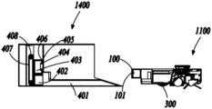
- Fig. 1 is a schematic diagram of a robot cleaning system provided by an embodiment of the present invention
- Fig. 2 is a schematic diagram of the mopping module of the robot cleaning system provided in an embodiment of the present invention in the first state;
- Fig. 3 is a schematic diagram of the mopping module of the robot cleaning system provided in an embodiment of the present invention in a second state;
- Fig. 4 is a schematic diagram of the mopping module of the robot cleaning system provided in an embodiment of the present invention in a second state;
- Fig. 5 is a schematic diagram of a cleaning robot in a robot cleaning system provided in an embodiment of the present invention when it is in a raised state;
- Fig. 6 is a schematic diagram of a cleaning robot in a robot cleaning system provided in an embodiment of the present invention when it is in a raised state;
- Fig. 7 is a schematic diagram of the mopping module of the robot cleaning system provided in an embodiment of the present invention returning to the base station in the second state;
- Fig. 8 is a schematic diagram of a robot cleaning system picking up an old mop according to an embodiment of the present invention.
- Fig. 9 is a schematic diagram of the robot cleaning system provided by an embodiment of the present invention exiting the dirty cloth box after removing the old mop;
- Fig. 10 is a schematic diagram of a robot cleaning system acquiring a new mop according to an embodiment of the present invention.
- Fig. 11 is a schematic diagram of the mopping module of the robot cleaning system in the first state in the base station according to an embodiment of the present invention
- Fig. 12 is a schematic diagram of the mopping module of the robot cleaning system shown in Fig. 11 in a second state in the base station;
- Fig. 13 is a schematic diagram of the robot cleaning system shown in Fig. 11 replacing the mop in the base station;
- Fig. 14 is a schematic diagram of the dirty cloth box and the clean cloth box of the robot cleaning system provided at an angle according to an embodiment of the present invention
- Fig. 15 is a schematic diagram of turning over the floor mopping module to the second state by the turning mechanism provided by an embodiment of the present invention
- Fig. 16 is a schematic diagram of a turning mechanism provided by an embodiment of the present invention.
- Fig. 17 is a schematic diagram of a driving mechanism provided by an embodiment of the present invention.
- Fig. 18 is a schematic diagram of lifting the mopping module by the driving mechanism provided by an embodiment of the present invention.
- Fig. 19 is a schematic diagram of turning over the mopping module by the driving mechanism provided by an embodiment of the present invention.
- Fig. 20 is a schematic diagram of a robot cleaning system provided by the present invention.
- Fig. 21 is a schematic diagram of a flipper provided in an embodiment of the present invention in a closed state
- Fig. 22 is a schematic structural view of the flipper in an open state according to an embodiment of the present invention.
- Fig. 23 is a schematic structural view of the flipper in another open state provided by an embodiment of the present invention.
- Fig. 24 is a schematic structural view of the mopping base provided by an embodiment of the present invention when the cleaning layer is removed from the cleaning cloth box;
- Fig. 25(a) is a schematic diagram of the cleaning layer removal mechanism provided by an embodiment of the present invention reaching the cleaning layer removal position;
- Fig. 25(b) is a schematic diagram of removing the cleaning layer by the cleaning layer removal mechanism provided by an embodiment of the present invention.
- Fig. 26(a) is a schematic diagram of the mopping module provided by an embodiment of the present invention moving toward the dirty cloth box and the turning member is in a closed state;
- Fig. 26(b) is a schematic diagram of the driving device driving the turning member to open according to an embodiment of the present invention.
- Figure 26(c) is a schematic diagram of the hook body provided by an embodiment of the present invention when the cleaning layer is removed;
- Fig. 26(d) is a schematic diagram of the mopping module leaving the dirty cloth box provided by an embodiment of the present invention.
- the fixed position mentioned in the present disclosure refers to non-active movement, so it can be understood as the position is constant or the position is basically constant, and the meaning of the position is basically constant, for example, the position is slightly changed due to the action of an external force).
- the problem of how to maintain the cleaning robot with dragging function is to return the cleaning robot to the base station after the cleaning robot has been working for a period of time, and clean the cleaning robot through the automatic cleaning system set in the base station.
- this automatic cleaning robot solution reduces manual intervention, the cleaning effect of the mop is not ideal, and there will be sewage residue on the mop and the base station after cleaning; in addition, when cleaning the mop, the noise is relatively large, affect user experience.
- the present disclosure provides a robot cleaning system.
- the mop can be replaced for the cleaning robot to achieve the purpose of cleaning the cleaning robot, which avoids the automatic cleaning process of the cleaning robot in the prior art , thereby avoiding the problems of sewage residue and noise generated during at least part of the cleaning process, and improving user experience.
- the robot cleaning system includes: a cleaning robot and a base station for the cleaning robot to dock.
- the above-mentioned cleaning robot includes: a main body, which has a front end; a walking module, which is arranged on the main body, and drives the cleaning robot to move on the working surface;
- the cleaning layer can be replaced to form a cleaning surface, and the cleaning surface is used to clean the working surface, especially to clean the working surface when the cleaning robot is working;
- the mopping module includes at least a first state and a second state , the mopping module is movably connected to the main body to switch between the first state and the second state; in the first state, the cleaning surface is attached to the working surface; in the second state, the cleaning surface is separated from the working surface
- the driving module used to drive the mopping module to switch between the first state and the second state
- the control module at least used to control the driving module to drive the mopping module to switch from the first state to the second state when the cleaning layer needs to be replaced. the second state;
- control module can also control the driving module to drive the mopping module to switch from the first state to the second state.
- the mopping module is set not to hinder the movement of the cleaning robot.
- the cleaning system also includes: a cleaning layer replacement mechanism; when the mopping module is in the second state, the cleaning layer replacement mechanism is configured to operably act on the cleaning layer and/or the mopping base to replace the cleaning layer for the mopping module.
- the cleaning layer replacement mechanism can be arranged on the cleaning robot, for example, the cleaning layer replacement mechanism includes a cleaning layer detachment mechanism for disassembling the cleaning layer such as a turning member arranged on the cleaning robot; it can also be arranged on the base station, such as The cleaning layer replacement mechanism is set on the hook body on the base station and other cleaning layer removal mechanisms for disassembling the cleaning layer; of course, a part can also be arranged on the cleaning robot, and a part is arranged on the base station.
- the cleaning layer removal mechanism includes both The turning part on the base station also includes a hook body arranged on the base station; of course, in other embodiments, the cleaning layer replacement mechanism may also include a dirty cloth bin for storing dirty cloth and/or a clean cloth bin for new cloth, The dirty cloth warehouse and/or the clean cloth warehouse are arranged on the base station; and the cleaning layer removal mechanism is arranged on the cleaning robot or on the base station; it can be understood that the above-mentioned mechanisms with different functions can be arranged according to requirements (such as space layout) and the like This disclosure does not specifically limit it.
- the above-mentioned replacement/replacement should be understood as including disassembly and installation, that is, the replacement of the cleaning layer (such as a mop) includes at least one of the disassembly and installation of the cleaning layer, for example, when the mopping base (such as mopping the floor) does not have a mop
- changing the cleaning layer means installing an unused cleaning layer; if there is a cleaning layer on the mopping floor, changing the mopping cloth can include the removal of the cleaning layer on the mopping floor and the installation of an unused cleaning layer;
- the cleaning layer usually refers to the used cleaning layer, that is, the dirty and unclean cleaning layer, while the unused cleaning layer usually refers to the new and clean cleaning layer.
- the cleaning robot needs to replace the mop and can detect the dirtyness of the cleaning layer.
- the degree of contamination, obtaining the elapsed working time of the cleaning robot using the cleaning layer or the cleaned cleaning area using the cleaning layer, or receiving a replacement instruction from the user, etc., will not be described in detail in this embodiment.
- the removal and installation of the cleaning layer or the removal and installation of the cleaning layer can be determined according to user needs, or can be determined according to the program to detect whether the mopping floor has a cleaning layer when the cleaning robot needs to replace the mop. Do limited.
- the cleaning layer replacement mechanism includes: a cleaning layer detaching mechanism for detaching the cleaning layer (such as mop paper).
- the cleaning layer removal mechanism is arranged on the base station; further, the cleaning layer removal mechanism includes a hook body; the hook body is arranged on the base station.
- the hook body can be arranged on the dirty cloth box; of course, in other embodiments, the hook body can also be arranged on the outside of the dirty cloth box, such as hook
- the hook body is located between the mopping floor and the dirty cloth box, and the setting position of the hook body can be determined according to actual needs, so as to facilitate disassembly.
- the mopping floor has a detachment area, and the detachment area can cooperate with the cleaning layer detachment mechanism to remove the cleaning layer from the mopping floor.
- the dismounting area includes a cloth removal groove, and the outer edge of the mopping floor is recessed toward the inside of the mopping floor to form a cloth removal groove;
- the cleaning layer removal mechanism includes a hook body; the hook body can cooperate with the cloth removal groove to remove the cleaning layer from the mop floor Remove the floor.
- the cloth removal groove can be, for example, a dismounting through hole that cooperates with the hook body.
- the cleaning layer has a part covering the cloth removal groove, and the hook body can pass through the cloth removal groove to hook the part of the cleaning layer covering the cloth removal groove, thereby removing the cleaning layer from the mopping floor.
- the mopping module and the cleaning layer removal mechanism can move to the same preset position; on the other hand, the state of the mopping module and the cleaning layer removal mechanism needs to be Matching, such as the inclination angle of the removal area, needs to match the inclination angle of the cleaning layer removal mechanism.
- the cleaning system includes a mop cleaning layer removal location configured to separate or remove the mopping floor from the cleaning layer.
- the cleaning layer removal mechanism is configured to pick up the cleaning layer on the mopping module at the cleaning layer removal position. Picking up here can be understood as, for example, that the cleaning layer detaching mechanism is in contact with the cleaning layer and facilitates removal of the cleaning layer.
- the hook body and the cloth removal groove can be in contact with each other, and then the two can be displaced to remove the cleaning layer from the mopping floor.
- the hook body can pass through the cloth removal groove, hook the part of the cleaning layer covering the cloth removal groove, and then generate a further relative displacement through the two, thereby removing the cleaning layer from the mopping floor.
- the cleaning system includes a first transmission mechanism configured to drive at least one of the cleaning layer detachment mechanism and the mopping module (especially the mopping floor) to move, so that the mopping module and the cleaning layer detachment mechanism generate Relative displacement, so that the cleaning layer on the mopping module is separated from the mopping module.
- the first transmission mechanism is configured to drive at least one of the cleaning layer detachment mechanism and the mopping module (especially the mopping floor) to move to the cleaning layer detachment position;
- at least one of the cleaning layer removal mechanism and the mopping module (especially the floor mopping module) is further driven to move, so that the cleaning layer on the mopping module is separated from the mopping module.
- the first transmission mechanism can be, for example, a mechanical arm that drives the cleaning layer removal mechanism, a moving part (such as a telescopic mechanism) that drives the mopping module, a walking module that drives the cleaning robot to move and thus drives the mopping module, etc.
- the cleaning layer removal position setting can be set according to requirements, for example, the mopping floor in the second state is just at the cleaning layer removal position; of course, the cleaning layer removal mechanism can be preset at the cleaning layer removal position, so that the When the movement of the first transmission mechanism is simplified.
- the cleaning layer disassembly mechanism can be moved, and the mopping module (especially the mopping floor) cannot be moved; it can also be that the cleaning layer disassembly mechanism does not move, and the mopping module moves; It is also possible that the mopping module and the cleaning layer removal mechanism both move.
- mopping module moves can be the passive movement that the motion of cleaning robot produces, also can drive the active motion that mopping module carries out by additionally arranging active motion mechanism (for example moving part); The active movement may also be a fixed position relative to the cleaning robot, and the passive movement is driven by the cleaning robot; this disclosure does not limit it.
- the first transmission mechanism includes a first moving mechanism configured to drive the cleaning layer removal mechanism to move; during at least part of the process of separating the cleaning layer on the mopping module from the mopping module, The positions of the cleaning robot and the mopping module are fixed, and the first moving mechanism drives the cleaning layer removal mechanism to move, so that the cleaning layer removal mechanism generates a displacement relative to the mopping module.
- the above-mentioned first moving mechanism is, for example, a mechanical arm that drives the cleaning layer removal mechanism to move.
- the first transmission mechanism includes a moving part, which is arranged on the cleaning robot and is configured to drive the movement of the mopping module; when separating the cleaning layer on the mopping module from the mopping module, During at least part of the process, the cleaning robot and the cleaning layer removal mechanism are fixed in position, and the moving part drives the mopping module to move, so that the mopping module is displaced relative to the cleaning layer removal mechanism;
- the first transmission mechanism includes the walking module, and during at least part of the process of separating the cleaning layer on the mopping module from the mopping module, the position of the cleaning layer removal mechanism is fixed.
- the position of the mopping module is fixed relative to the cleaning robot; the walking module drives the cleaning robot to move, so that the mopping module generates a displacement relative to the cleaning layer removal mechanism, for example, the walking module drives the cleaning robot
- the robot moves to the cleaning layer removal position, so that the cleaning layer removal mechanism picks up the cleaning layer on the mopping module at the cleaning layer removal position, and further, the walking module drives the cleaning robot to continue moving, so that the cleaning layer is removed
- the mechanism removes the cleaning layer from the mopping module or the mopping floor to realize the separation of the cleaning layer and the mopping module.
- the mopping module is driven by the movement of the cleaning robot, which simplifies the system structure and reduces the cost.
- the cleaning layer removal mechanism is a hook body; the removal area includes a cloth removal slot, and at the cleaning layer removal position, the hook body can pass through the corresponding cloth removal slot.
- hook bodies which are respectively arranged on two opposite side walls of the dirty cloth box; there are two cloth removal grooves, which are arranged on both sides of the mopping floor;
- the line connecting the center of the cloth removal groove is parallel; or in other words, the line connecting the center of the hook body is parallel to the abutment surface of the mopping base or parallel to the cleaning surface of the cleaning layer.
- the cleaning layer replacement mechanism includes a dirty cloth box for storing the cleaning layer separated from the mopping module.
- the removed cleaning layer may be, for example, a used sheet mop or a dirty sheet mop.
- the above-mentioned sheet-like mop may also be paper-based disposable mop paper.
- Mode A The dirty cloth box is set on the moving path of the separated cleaning layer
- Method B The removal position of the cleaning layer is located in the dirty cloth box
- Mode C The cleaning layer removal mechanism is located on or inside the dirty cloth box.
- the dirty cloth box is arranged on the moving path of the cleaning layer separated from the mopping module, so that the cleaning layer falls into the dirty cloth box.
- the cleaning layer detachment mechanism (such as a hook body) is arranged on the dirty cloth box.
- the cleaning layer detachment mechanism By installing the cleaning layer detachment mechanism on the dirty cloth box, the removed cleaning layer directly falls into the dirty cloth box.
- the cleaning layer is disassembled in the dirty cloth box, and the cleaning layer can also be dropped into the dirty cloth box.
- the interior of the dirty cloth box can also be provided with a maintenance part for supporting the removed cleaning layer, so that the removed cleaning layer can maintain the state when it is removed, and guide the path of removal;
- the portion may be, for example, a step or a slope, which is not limited in this embodiment.
- the separated cleaning layer can also be picked up and sent into the dirty cloth box by additionally setting a pick-up mechanism, or the separated cleaning layer can be manually picked up and put into the dirty cloth box.
- the dirt cloth bin has a first opening configured to allow the mopping module to reach in and leave the cleaning layer in the dirt cloth bin when the mopping module exits.
- the dirty cloth box includes a bottom and at least two opposite side walls, the side walls are connected to the bottom, the side walls and the bottom may form a first opening, wherein the first opening is opposite to the bottom.
- the first opening of the dirty cloth box faces the second direction; wherein, the first direction is the entry direction of the cleaning robot, For example, the direction in which the cleaning robot points to the base station; the second direction is opposite to the first direction; that is, the second direction is the outbound direction of the cleaning robot, such as the direction in which the base station points to the cleaning robot or the direction in which the cleaning robot is away from the base station;
- the first opening extends into the dirty cloth box and cooperates with the cleaning layer removal mechanism so that the mopping module leaves the first opening to leave the cleaning layer in the dirty cloth box.
- the cleaning layer detachment position or the cleaning layer detachment mechanism is arranged at the first opening of the dirty cloth box.
- the cleaning layer removal mechanism When the cleaning layer removal mechanism is arranged on the dirty cloth box (such as being arranged on the end of the side wall of the dirty cloth box away from the bottom) or in the dirty cloth box (such as being arranged at a preset position on the side wall of the dirty cloth box),
- the movement of the cleaning layer removal mechanism can be realized by the movement of the dirty cloth box. Therefore, the relative displacement of the cleaning layer removal mechanism or the mopping module (especially the mopping floor) is as follows: the dirty cloth box moves, thereby driving the cleaning layer to be removed.
- the mechanism moves passively, while the cleaning robot and mopping the floor do not move; the dirty cloth box does not move, and the cleaning layer removal mechanism does not move at this time, but the cleaning robot and/or mopping the floor move; the dirty cloth box moves, driving the cleaning layer removal mechanism passively moves, and at least one of the cleaning robot and the mopping also moves;
- the first transmission mechanism includes a second moving mechanism configured to drive the dirty cloth box to move; at least part of the cleaning layer on the mopping module is separated from the mopping module During the process, the position of the cleaning layer removal mechanism is fixed relative to the dirty cloth box, the position of the cleaning robot is fixed, and the position of the mopping module is fixed relative to the cleaning robot; the second moving mechanism drives the dirty cloth The box moves, thereby driving the cleaning layer dismounting mechanism to move, so that the cleaning layer dismounting mechanism generates a displacement relative to the mopping module.
- the second moving mechanism drives the dirty cloth box to move towards the mopping module, so that The floor mopping module stretches into the dirty cloth box through the first opening, and reaches a position in contact with the cleaning layer dismounting mechanism (such as the cleaning layer dismounting position), and by further moving, the cleaning layer is separated from the mopping module; then the second moving mechanism Drive the dirty cloth box to move in the opposite direction (direction away from the mopping module), so that the mopping module leaves the first opening, and when the mopping module leaves, the cleaning layer falls or has fallen into the dirty cloth box.
- the cleaning layer dismounting mechanism such as the cleaning layer dismounting position
- the second movement drives the dirty cloth box to move towards the mopping module, so that the mopping module reaches the position in contact with the cleaning layer removal mechanism, and through further movement, it extends into the dirty cloth box through the first opening, for example, moves to a distance of 0 from the bottom position, so that the cleaning layer is separated from the mopping module; then the second moving mechanism drives the dirty cloth box to move the preset distance in the opposite direction (direction away from the mopping module), and when the mopping module leaves the first opening, the cleaning layer falls into or has fallen into the dirty cloth bin.
- the first transmission mechanism is at least configured to drive the mopping module to move during at least part of the process of separating the cleaning layer on the mopping module from the mopping module; wherein, During at least part of the separation of the cleaning layer on the mopping module from the mopping module, the position of the dirty cloth box is fixed.
- the implementation of mopping module movement includes at least one of the following:
- the first transmission mechanism includes the walking module
- the position of the dirty cloth box is fixed, the position of the cleaning layer removal mechanism is fixed relative to the position of the dirty cloth box, and the mopping
- the position of the floor module is fixed relative to the cleaning robot; the walking module drives the cleaning robot to move toward the dirty cloth box, thereby driving the mopping module to move, so that the mopping module and the cleaning layer removal mechanism produce relative displacement.
- the first transmission mechanism includes a moving part, which is arranged on the cleaning robot and configured to drive the mopping module to move;
- the position of the dirty cloth box is fixed, the position of the cleaning layer removal mechanism is fixed relative to the position of the dirty cloth box, and the cleaning The position of the robot is fixed; the moving part drives the mopping module to move towards the dirty cloth box, so that the mopping module and the cleaning layer removal mechanism generate relative displacement.
- the kinematic relationship during disassembly is matched with the kinematic relationship during installation.
- dismounting the mopping module moves and the dirty cloth box does not move;
- the mopping module moves, and the clean cloth box does not move; or, when disassembled, the mopping module does not move, and the dirty cloth box moves; during installation, the mopping module does not move, and the clean cloth box moves.
- the first transmission mechanism when disassembled, includes a moving part, which is arranged on the cleaning robot, and during at least part of the process of separating the cleaning layer on the mopping module from the mopping module, the The moving part drives the mopping module to move towards the dirty cloth box (or the cleaning layer removal mechanism), so that the mopping module and the dirty cloth box (or the cleaning layer removal mechanism) produce relative displacement; then during installation, the second transmission
- the mechanism includes a moving part, which is arranged on the cleaning robot. During at least part of the process of installing the cleaning layer in the cleaning cloth box on the mopping module, the moving part drives the mopping module toward the clean The cloth box moves; making the mopping module and the clean cloth box produce relative displacement.
- the first transmission mechanism includes a moving part, which is arranged on the cleaning robot, and connects the cleaning layer on the mopping module with the mopping module During at least part of the separation process, the moving part drives the mopping module to move towards the dirty cloth box, so that the mopping module and the cleaning layer removal mechanism produce relative displacement; wherein, the cleaning layer on the mopping module During at least part of the process of separating from the mopping module, the position of the dirty cloth box is fixed, the position of the cleaning layer removal mechanism is fixed relative to the dirty cloth box, and the position of the mopping module is fixed relative to the cleaning robot During installation, the second transmission mechanism includes a moving part, which is arranged on the cleaning robot, and the cleaning layer in the cleaning cloth box is installed in at least part of the process of the mopping module, and the moving part drives the The mopping module moves towards the cleaning cloth box; the mopping module and the cleaning cloth box produce relative displacement; wherein, during at least part of the process where
- the first transmission mechanism when disassembled, includes a walking module, which is arranged on the cleaning robot, and during at least part of the process of separating the cleaning layer on the mopping module from the mopping module, The walking module drives the cleaning robot to move, thereby driving the mopping module to move towards the dirty cloth box (or the cleaning layer disassembly mechanism), so that the mopping module and the dirty cloth box (or the cleaning layer disassembly mechanism) produce relative displacement; Then during installation, the second transmission mechanism includes the walking module, and during at least part of the process of installing the cleaning layer in the cleaning cloth box on the mopping module, the walking module drives the cleaning robot to move, thereby driving the The mopping module moves toward the clean cloth box, so that the mopping module and the clean cloth box generate relative displacement. .
- the first transmission mechanism includes a walking module, which is arranged on the cleaning robot, and connects the cleaning layer on the mopping module with the mopping module During at least part of the separation process, the walking module drives the cleaning robot to move, thereby driving the mopping module to move towards the dirty cloth box; wherein, the cleaning layer on the mopping module is separated from the mopping module During at least part of the process, the position of the cleaning layer removal mechanism is fixed relative to the dirty cloth box, and the position of the mopping module is fixed relative to the cleaning robot.
- the second transmission mechanism includes the walking module, and drives the cleaning robot to move during at least part of the process of installing the cleaning layer in the cleaning cloth box on the mopping module, thereby driving the mopping module Moving towards the clean cloth box; during at least part of the process in which the cleaning layer in the clean cloth box is installed on the mopping module, the position of the mopping module relative to the cleaning robot is fixed, and the clean cloth The position of the box is fixed.
- the first transmission mechanism when disassembled, includes a second moving mechanism, at least configured to drive the The dirty cloth box moves so that the cleaning layer removal mechanism is displaced relative to the mopping module; wherein, during at least part of the process of separating the cleaning layer on the mopping module from the mopping module, the cleaning layer removal mechanism is relatively The position of the dirty cloth box is fixed, the position of the cleaning robot is fixed, and the position of the mopping module relative to the cleaning robot is fixed.
- the second transmission mechanism includes a third moving mechanism, which is at least configured to drive the cleaning cloth box toward The mopping module moves; wherein, during at least part of the process of installing the cleaning layer in the cleaning cloth box on the mopping module, the positions of the cleaning robot and the mopping module are fixed.
- the kinematic relationship during disassembly may not match the kinematic relationship during installation.
- the mopping module moves, but the dirty cloth box does not move; when installing, the mopping module does not move.
- the mopping module does not move, and the dirty cloth box moves; when installing, the mopping module moves, but the clean cloth box does not move; at this time, the difficulty of control increases and the number of moving mechanisms increases. , is not conducive to cost reduction.
- the process of separating the cleaning layer on the mopping module from the mopping module at least includes a process in which at least one of the dirty cloth box (or cleaning layer removal mechanism) and the mopping module moves to the cleaning layer removal position , the process of contacting the cleaning layer on the mopping module with the cleaning layer detachment mechanism, the process of further displacement between the cleaning layer detachment mechanism and the cleaning layer on the mopping module, etc.
- the process of installing the cleaning layer in the cleaning cloth box on the mopping module at least includes at least one of the cleaning cloth box or the mopping module moving to the installation position of the cleaning layer, the cleaning layer and the mopping module.
- the base station also includes an in-position detection device configured to obtain the position of the mopping floor, the cleaning layer removal mechanism or the dirty cloth box, so as to determine whether the mopping floor, the cleaning layer removal mechanism Or whether the dirty cloth box is moved in place so as to realize the removal of the mopped floor;
- the in-position detection device includes, for example, a position sensor group or a limit mechanism.
- the base station includes: a first position detection device configured to detect whether the dirty cloth box has reached the cleaning layer removal position, so as to determine whether to perform subsequent cleaning layer removal operations.
- the dirty cloth box when the dirty cloth box (or the cleaning layer removal mechanism provided thereon) is not in alignment with the mopping module, the dirty cloth box is configured to be driven by the second moving mechanism Move down to the alignment position corresponding to the alignment state, so that the cleaning layer removal mechanism and the mopping module are in the alignment state.
- the alignment position can be realized by a sensor or a limit mechanism on the base station.
- the above-mentioned moving part can be a telescopic mechanism, which can drive the mopping module (especially the mopping base) to perform stretching and contraction movements; further, the telescopic mechanism can be a telescopic rod, which has a simple structure Easy to implement.
- the moving part can also be a manipulator or other mechanical mechanism, as long as it can drive the mopping module to move, which is not limited in this embodiment.
- the cleaning layer replacement mechanism includes a cleaning layer detachment mechanism, the cleaning layer detachment mechanism is arranged on the cleaning robot, and is configured to drag the The cleaning layer on the floor module is separated from the mopping module; further, the cleaning layer detaching mechanism includes an overturning member 500, which is arranged on the cleaning robot.
- the turning member 500 is set on the mopping module (especially the mopping base 1011 ).
- the turning member may be a clamping mechanism, wherein the clamping mechanism may be, for example, a mechanical claw.
- the turning member 500 has an open state and a closed state.
- the cleaning layer 101 can be separated from the mopping module; when the turning member 500 is in the closed state, The cleaning layer is installed on the mopping module.
- the flipping member when the flipping member is in the open state, the flipping member forms a first angle with the attachment surface; when the flipping member is in the closed state, the flipping member forms a second angle with the attachment surface; The first angle is different from the second angle.
- the cleaning system includes a movement mechanism configured to drive the cleaning layer detachment mechanism (for example, the turning member 500 ) to move, so that the cleaning layer detachment mechanism and the cleaning layer detachment mechanism
- the mopping module generates relative displacement so that the cleaning layer on the mopping module is separated from the mopping module; wherein, during at least part of the process of separating the cleaning layer on the mopping module from the mopping module , the positions of the cleaning robot and the mopping module are fixed.
- the moving mechanism may be, for example, a driving device 601 that drives the opening and closing of the flipping member, so that the flipping member is switched between an open state and a closed state.
- the driving device 601 includes a driving motor, for example, and the driving motor drives the flipping member 500 to rotate around the shaft 602. .
- the motion mechanism includes a driving device 601 configured to drive the turning member 500 to switch from the closed state to the open state, thereby mopping the floor
- the cleaning layer 101 on the module is separated from the mopping module (especially the mopping base 1011 ).
- the mopping base (such as a mopping floor) has a detachment area that can cooperate with a cleaning layer detachment mechanism to remove the cleaning layer from the mopping floor.
- the motion mechanism includes a driving device 601, and the driving device 601 is configured to drive the turning member 500 to switch from the open state to the closed state, so that the clean cloth box 402
- the inner cleaning layer 101 is installed on the mopping module (especially the mopping base 1011).
- the cleaning system includes a cleaning layer removal position for removing the cleaning layer on the mopping module; further, the cleaning layer removal mechanism is configured to separate the cleaning layer from the mopping module at the cleaning layer removal position. The mopping module is separated.
- the cleaning robot includes a first transmission mechanism for driving the mopping module to move, thereby driving The cleaning layer removal mechanism moves to the cleaning layer removal position.
- the first transmission mechanism includes a moving part, which is arranged on the cleaning robot and is configured to drive the mopping module to move to the cleaning layer removal position, so that the cleaning layer removal mechanism moves to the cleaning layer removal position, and then further passes the moving mechanism Drive the movement of the cleaning layer disassembly mechanism to realize the separation of the cleaning layer and the mopping module.
- the first transmission mechanism includes a walking module, which is configured to drive the mopping module to move to the cleaning layer removal position, so that the cleaning layer removal mechanism moves to the cleaning layer removal position, and then the movement mechanism further drives the cleaning layer removal mechanism to open. Separation of the cleaning layer from the mopping module.
- the mopping module is driven by the movement of the cleaning robot, which simplifies the system structure and reduces the cost.
- the setting of the removal position of the cleaning layer can be set according to requirements.
- the mopping floor in the second state is just at the removal position of the cleaning layer.
- the cleaning layer separates the cleaning layer from the mopping module.
- the mopping module can be provided with a button to control the switch of the turning member, and the opening and closing of the turning member can be realized through manual or automatic control.
- the cleaning layer replacement mechanism includes a dirty cloth box 403 for storing the cleaning layer 101 separated from the mopping module.
- the dirty cloth box is arranged on the moving path of the cleaning layer separated from the mopping module, so that the cleaning layer falls into the dirty cloth box.
- Method B The removal position of the cleaning layer is located in the dirty cloth box
- the cleaning layer detachment position is set in the dirty cloth box, so that the cleaning layer detachment mechanism (such as a turning member) is disassembled at the cleaning layer detachment position, and the cleaning layer can also be dropped into the dirty cloth box.
- the cleaning layer detachment mechanism such as a turning member
- the first transmission mechanism is at least configured to drive the mopping module to move to the cleaning layer removal position; wherein, at least when the first transmission mechanism drives the mopping module to the cleaning layer removal position During part of the process, the position of the dirty cloth bin is fixed.
- the first transmission mechanism includes a walking module; during at least part of the movement of the mopping module to the cleaning layer removal position, the position of the dirty cloth box is fixed, and the position of the cleaning layer removal mechanism is relatively fixed relative to the mopping module.
- the position of the mopping module is fixed relative to the cleaning robot; the walking module drives the cleaning robot to move toward the dirty cloth box, thereby driving the mopping module to move, so that the cleaning layer removal mechanism moves to the cleaning layer removal position.
- the first transmission mechanism includes a moving part, which is arranged on the cleaning robot and configured to drive the mopping module to move;
- the moving part drives the mopping module to move towards the dirty cloth box, so that the cleaning The layer removal mechanism moves to the cleaning layer removal position.
- Mode C The cleaning layer removal mechanism is in the dirty cloth box.
- the cleaning layer detachment mechanism in the second state is just in the dirty cloth box; of course, in another embodiment, when the cleaning layer detachment mechanism is not in the dirty cloth box, the cleaning layer is detached A mechanism (such as a flipper) extends into the dirty cloth bin.
- the cleaning layer disassembly mechanism extends into the dirty cloth box
- the mopping module especially the mopping floor
- the cleaning layer disassembly mechanism on it do not move
- the dirty cloth box does not move
- the mopping module moves (thereby driving the cleaning layer removal mechanism on it to move); it can also be that the mopping module and the dirty cloth box all move.
- mopping module moves can be the passive movement that the motion of cleaning robot produces, also can drive the active motion that mopping module carries out by additionally setting active movement mechanism (for example moving part);
- active movement mechanism for example moving part
- mopping module can be relatively cleaning robot
- the active movement may also be a fixed position relative to the cleaning robot, and the passive movement is driven by the cleaning robot; this disclosure does not limit it.
- the first transmission mechanism includes a second moving mechanism configured to drive the dirty cloth box to move; during at least part of the process when the cleaning layer removal mechanism on the mopping module extends into the dirty cloth box, the cleaning robot and the mopping module
- the position is fixed, and the position of the cleaning layer removal mechanism on the mopping module is also fixed.
- the first moving mechanism drives the dirty cloth box to move, so that the cleaning layer removal mechanism extends into the dirty cloth box; the cleaning layer removal mechanism extends into the dirty cloth box
- the cleaning layer removal mechanism moves relative to the mopping module under the drive of the moving mechanism (such as a driving device), and switches from the closed state to the open state, thereby removing the cleaning layer from the mopping module.
- the removed cleaning layer Dropped into the Dirty Cloth Chest.
- the above-mentioned second moving mechanism includes, for example, guide rails and driving motors that drive the movement of the dirty cloth box.
- the first transmission mechanism includes a moving part, which is arranged on the cleaning robot and is configured to drive the movement of the mopping module; during at least part of the process when the cleaning layer removal mechanism extends into the dirty cloth box, the cleaning robot and the dirty cloth box are fixed in position , the moving part drives the mopping module to move, thereby driving the cleaning layer removal mechanism on the mopping module to extend into the dirty cloth box.
- the first transmission mechanism includes a walking module, and during at least part of the process when the cleaning layer removal mechanism extends into the dirty cloth box, the position of the dirty cloth box is fixed, and the position of the mopping module is fixed relative to the cleaning robot;
- the walking module drives the cleaning robot to move, and drives the mopping module to move, so that the cleaning layer removal mechanism on the mopping module extends into the dirty cloth box.
- the mopping module is driven by the movement of the cleaning robot, which simplifies the system structure and reduces the cost.
- the dirty cloth box has a first opening configured to allow the mopping module to enter and leave the cleaning layer in the dirty cloth box when the mopping module leaves.
- the dirty cloth box includes a bottom and at least two opposite side walls, the side walls are connected to the bottom, the side walls and the bottom can form a first opening, wherein the first opening is opposite to the bottom.
- the movement mechanism drives the cleaning layer dismounting mechanism (such as the flipper) to switch from the closed state to the open state, so that the cleaning layer is separated from the mopping module, and the cleaning layer is left in the dirty cloth box when the mopping module leaves the first opening.
- the cleaning layer removal position is set at a position close to the bottom of the dirty cloth box.
- the base station In order to determine whether the mopping floor, the cleaning layer removal mechanism or the dirty cloth box have reached the designated position, further, the base station also includes an in-position detection device configured to obtain the position of the mopping floor, the cleaning layer removal mechanism or the dirty cloth box, so as to determine whether the mopping floor, cleaning layer removal mechanism or the dirty cloth box Whether the cleaning layer removal mechanism or the dirty cloth box is moved in place to realize the removal of the cleaning layer;
- the in-position detection device includes, for example, a position sensor group or a limit mechanism.
- the base station includes: an in-position detection device for detecting whether the mopping floor has reached the cleaning layer removal position, so as to determine whether to perform a subsequent cleaning layer removal operation.
- the mopping board when the mopping floor (or the cleaning layer removal mechanism provided thereon) is not in alignment with the dirty cloth box, the mopping board is configured to move under the drive of the first transmission mechanism to the alignment position corresponding to the alignment state, so that the cleaning layer removal mechanism is aligned with the mopping module.
- the alignment position can be realized by a sensor or a limit mechanism on the cleaning robot or the base station.
- the mopping base 1011 in order to improve the firmness of the cleaning layer and prevent it from falling off during the movement of the cleaning robot or mopping the floor, further, the mopping base 1011 includes Paste area capable of bonding the cleaning layer.
- the turning member 500 in order to improve the firmness of the cleaning layer, has an adhesive surface capable of bonding the cleaning layer.
- the removal area includes a cloth removal groove, and the outer edge of the mopping floor is recessed to the inside of the mopping floor to form a cloth removal groove;
- the cleaning layer removal mechanism includes a hook body 404 arranged on the base station (especially the dirty cloth box 403); the hook body Can be used in conjunction with the cloth removal channel to remove the cleaning layer from the mopped floor.
- the cloth removal groove may be, for example, a disassembly through hole matched with the hook body.
- the cleaning layer has a part covering the cloth removal groove
- the hook body can pass through the cloth removal groove, and hook the part of the cleaning layer covered in the cloth removal groove, so as to remove the cleaning layer from the mopping floor. Mopping the floor in the paste area can improve the reliability of removal.
- the cleaning layer removal mechanism also includes a hook body arranged on the base station (especially the dirty cloth box).
- the movement mechanism drives the cleaning layer removal mechanism (such as the flipper) arranged on the cleaning robot (especially the mopping module), so that the flipper is in an open state; for example, the hook body 404
- the movement mechanism (such as the driving device 601) drives the cleaning layer removal mechanism (such as flipper 500), so that the flipper is in an open state; then the cleaning layer 101 is operated to complete subsequent removal by the hook body 404 on the dirty cloth box, so that the cleaning layer 101 falls into the dirty cloth box 403.
- the cleaning layer detaching mechanism includes a hook disposed on the base station
- the process of detaching the cleaning layer by the hook body can refer to the relevant discussions above, and will not be repeated here.
- the cleaning layer removal mechanism can also be a manipulator or other mechanisms in addition to the above-mentioned hooks (such as paper removal hooks) and flippers (such as clamping mechanisms), as long as the cloth can be removed.
- the mopping base is provided with a connection area for connecting the cleaning layer
- a connection area for connecting the cleaning layer is provided on the cleaning layer detachment mechanism on the cleaning robot.
- the mopping base (such as a mopping floor) is provided with a connecting area for connecting the cleaning layer.
- the connecting area includes an adhesive area, to which the cleaning layer can be adhered; specifically, the adhesive area includes an adhesive portion, to which the cleaning layer can be adhered, so as to realize the connection between the mopping floor and the cleaning layer.
- the sticking area can be, for example, a Velcro.
- a cleaning area for connecting the cleaning layer can be set on the turning member
- the turning member has an adhesive surface capable of adhering the cleaning medium, and the connection area includes the adhesive surface.
- both the turning member and the mopping base can be provided with a cleaning area connected to the cleaning layer.
- the cleaning system of the present application (especially the cleaning layer replacement mechanism) includes a cloth box configured to accommodate the cleaning layer to be installed on the mopping module.
- the cleaning layer is a sheet-like mop; when there are at least two sheet-like mops, at least two sheets of the sheet-like mop are arranged in the cleaning cloth box in a stacked manner.
- the "stacking" mentioned herein may be partially overlapping or completely overlapping, that is, when there are at least two first sheet mop cloths, the first sheet mop cloths are at least partially overlapped when arranged.
- the connection position will be adjusted adaptively to connect with the corresponding cleaning layer, that is, the cleaning layer can have different placement positions, and the mopping floor can have different positions.
- the connection position corresponds to the placement position, so that the corresponding cleaning layer can be taken out; preferably, the cleaning layer is completely overlapped when stacked.
- the occupied space of the cleaning layer can be saved, for example, the cleaning cloth can be reduced
- the size of the box since the cleaning layer can be connected at the same position every time, it is simple and convenient to take the cleaning layer every time.
- a cleaning layer installation position can be preset, and the mopping module and the cleaning cloth box move to the installation position to facilitate docking;
- the state of the mopping module and the clean cloth box needs to match, for example, the inclination angle of the mopping module (when connected to the unused cleaning layer, for example, in the second state) relative to the direction of the station, and the state of the clean cloth box.
- the opening orientation of the cloth box and the inclination angle of the cleaning layer in the clean cloth box need to match.
- the cleaning system includes a cleaning deck mounting location configured to mount the cleaning deck to a mopped floor.
- the mopping floor is configured to be connected with the cleaning layer on the cleaning cloth box at the installation position of the cleaning layer.
- the mopping floor can be in contact with the cleaning layer to install the cleaning layer on the mopping floor.
- the layer is more firmly installed on the mop floor.
- the cleaning layer includes a cleaning layer dismounting mechanism arranged on the cleaning robot, for example, when a flipping member is arranged on the mopping module, in order to install the cleaning layer on the mopping floor, mopping the floor or
- the turning part is provided with a connecting area connecting the cleaning layer; when considering that the mopping floor or the turning part is not provided with a connecting area connecting the cleaning layer, in order to fix the cleaning layer on the mopping floor, when the cleaning layer is in contact with the mopping floor or in the cleaning layer
- the moving mechanism (such as a driving device) drives the cleaning layer dismounting mechanism (especially the turning piece) that is arranged on the cleaning robot (especially the mopping base) to move, so that the cleaning layer removing mechanism (especially the turning piece) is switched to closed state, thereby installing the cleaning layer on the mopping module.
- the mopping floor is provided with a connection area (such as a pasting area) connecting the cleaning layer or the flipper is provided with a connection area (such as an adhesive surface) connecting the cleaning layer; after the mopping floor can be in contact with the cleaning layer; after the mopping floor can be in contact with the cleaning layer
- a connection area such as a pasting area
- the cleaning layer can also be achieved by the following methods: when the mopping floor or the turning piece is in contact with the cleaning layer or When the cleaning layer is installed in the position, the moving mechanism (such as a driving device) drives the cleaning layer dismounting mechanism (especially the turning piece) that is arranged on the cleaning robot (especially the mopping base) to move, so that the cleaning layer removing mechanism (especially the turning piece) ) to the closed state, at this time, the cleaning layer removal mechanism can also play the role of installation or fixing.
- the movement mechanism drives the cleaning layer dismounting mechanism (especially the overturning piece) arranged on the cleaning robot (especially the mopping base) to move, so that the cleaning layer demounting mechanism (especially the overturning piece)
- the clean cloth box has an operating space for the movement of the cleaning layer's disassembly mechanism; or, after the cleaning layer is connected to the mopping module, outside the clean cloth box, the movement mechanism Drive the cleaning layer removal mechanism (especially the flipper) on the cleaning robot (especially the mopping base) to move, so that the cleaning layer removal mechanism (especially the flipper) is switched to the closed state to improve the firmness of the cleaning layer.
- the cleaning system includes a second transmission mechanism, which is configured to drive at least one of the cleaning cloth box and the mopping module (especially the mopping floor) to move, so that a relative displacement occurs between the mopping floor and the cleaning cloth box, so that The cleaning layer on the mopping module is installed on the mopping module.
- the second transmission mechanism is configured to drive at least one of the cleaning cloth box and the mopping module (especially mopping the floor) to move to the installation position of the cleaning layer, so that the cleaning layer in the cleaning cloth bin is installed on the cleaning layer. Mop the floor module; and when the mop floor and the clean cloth box are located at the installation position of the cleaning layer, at least one of the clean cloth box and the mop module (especially the mop floor) is driven to move further, so that the cleaning in the clean cloth box Layers are mounted to the mopping module.
- the cleaning cloth box and the mopping module especially mopping the floor
- the installation position of the cleaning layer can be set according to requirements, for example, the mopping floor in the second state is just at the installation position of the cleaning layer; of course, the cleaning cloth box can be preset at the installation position of the cleaning layer, so that The movement of the second transmission mechanism is simplified.
- the cloth box can be moved, and the mopping module (especially the floor mopping) can’t be moved;
- the ground module moves; it is also possible that both the mopping module and the cleaning cloth box move.
- mopping module moves can be the passive motion that the motion of cleaning robot produces, also can drive the active motion that mopping module carries out by additionally arranging active moving mechanism (for example moving part); Active movement; it can also be fixed relative to the cleaning robot, driven by the cleaning robot to perform passive movement; this disclosure does not limit it.
- the second transmission mechanism includes a third moving mechanism configured to drive the movement of the cleaning cloth box; when the cleaning layer in the cleaning cloth box is installed on the mopping module During at least part of the process, the positions of the cleaning robot and the mopping module are fixed, and the third moving mechanism drives the cloth cleaning box to move, so that the cloth cleaning box is displaced relative to the mopping module.
- the second transmission mechanism includes a moving part, which is arranged on the cleaning robot and is configured to drive the movement of the mopping module; when the cleaning layer in the cleaning cloth box is installed on the During at least part of the process of the mopping module, the cleaning robot and the cloth cleaning box are fixed in position, and the moving part drives the mopping module to move, so that the mopping module is displaced relative to the cloth cleaning box.
- the second transmission mechanism includes the walking module, and during at least part of the process of installing the cleaning layer of the cleaning cloth box on the mopping module, the position of the cleaning cloth box is fixed, so The position of the mopping module relative to the cleaning robot is fixed; the walking module drives the cleaning robot to move, so that the mopping module generates a displacement relative to the cleaning cloth box, for example, the walking module drives the cleaning robot to move to
- the installation position of the cleaning layer is such that the mopping module is connected to the cleaning layer in the cleaning cloth box at the installation position of the cleaning layer; Interaction force is generated to realize the stability of the connection between the cleaning layer and the mopping module.
- the mopping module is driven by the movement of the cleaning robot, which simplifies the system structure and reduces the cost.
- the base station also includes an in-position detection device configured to obtain the position of the mopping floor or the cleaning cloth box, so as to determine whether the mopping floor or the cleaning cloth box has moved in place, so as to realize cleaning layer installation;
- the base station includes: a second in-position detection device configured to detect whether the clean cloth box has reached the installation position of the cleaning layer, so as to determine whether to perform a subsequent installation operation of the cleaning layer.
- the mopping base (such as mopping the floor) includes a connection surface or an abutment surface, the connection surface is located on the lower surface of the mopping base, and is configured to connect the cleaning layer;
- the cleaning layer (such as mop or mop paper) has a cleaning surface and a non-cleaning surface, wherein the cleaning surface is used to perform cleaning work when it is in contact with the ground, and the non-cleaning surface is the side that is connected/adhered to the mopping floor or the non-cleaning surface is used for cleaning. Face the opposite side.
- the connecting surface or abutting surface of the mopping base and the cleaning surface of the cleaning layer in the cleaning cloth box are configured to be parallel to each other or, before the mopping floor is connected with the cleaning surface of the cleaning layer in the cleaning cloth box, the angle between the cleaning surface of the cleaning layer in the cleaning cloth box and the first direction is equal to the connecting surface of the mopping base body (or The angle formed by the contact surface) and the first direction.
- the first direction refers to a direction in which the cleaning robot points to the base station, for example, the direction is a horizontal direction parallel to a horizontal plane.
- the connecting surface (or abutment surface) of the mopping floor is parallel to the cleaning surface of the cleaning layer in the clean cloth box; or in other words, in the second state, the cleaning of the cleaning layer in the clean cloth box
- the angle formed between the surface and the first direction is equal to the angle formed between the connecting surface (or abutting surface) of the mopping floor and the first direction, wherein the first direction is the direction in which the cleaning robot points to the base station.
- the placement angle of the cleaning layer in the clean cloth box matches the angle of mopping the floor in the second state.
- the angle formed between the surface and the first direction is also any value greater than or equal to 30 degrees and less than or equal to 90 degrees; on the contrary, the angle formed between the cleaning surface of the cleaning layer in the cleaning cloth box and the first direction is greater than or equal to 30 degrees.
- the control module is at least configured to control the driving module to drive the mopping module to switch from the first state to the In the second state, the angle formed between the connecting surface of the mopping floor and the first direction is also any value greater than or equal to 30 degrees and less than or equal to 90 degrees.
- the connecting surface of the mopping module is perpendicular to the first direction; the cleaning surface of the cleaning layer in the cleaning cloth box is aligned with the first The direction is vertical, that is to say, in the clean cloth box, the cleaning layer is placed vertically;
- a support part is provided in the cleaning cloth box for supporting the cleaning layer, so that the cleaning layer accommodated in the cleaning cloth box
- the cleaning surface is at an angle to the first direction.
- the cleaning surface of the cleaning layer accommodated in the cloth box is at an angle greater than or equal to 30 degrees and less than or equal to 90 degrees with the first direction;
- the support part includes a fixing device, It is configured to fix the cleaning layer so that the cleaning surface of the cleaning layer accommodated in the cleaning cloth box is at right angles to the first direction.
- the value of the angle between the cleaning surface of the cleaning layer in the cleaning cloth box and the first direction is Any value greater than or equal to 45 degrees and less than or equal to 60 degrees; correspondingly, when the mopping module is in the second state, the angle between the connecting surface of the mopping module and the first direction is also greater than or equal to Any value equal to 45 degrees and less than or equal to 60 degrees.
- support parts such as slopes or steps can be provided in the clean cloth box to assist in maintaining the state of the cleaning layer, and at the same time can guide the user to place the cleaning layer.
- the slope or steps are especially suitable for the storage of the clean cloth box.
- the cleaning surface of the cleaning layer is placed at an acute angle to the first direction, for example, the value of the acute angle is greater than or equal to 30 degrees and less than or equal to 60 degrees.
- the mopping floor when the mopping floor is docked with the cleaning layer, the mopping floor needs to be able to reach into the clean cloth box.
- the cleaning cloth box has a second opening configured to allow the mopping module to protrude.
- the clean cloth box includes a bottom and at least two opposite side walls, the side wall of the clean cloth box is connected with the bottom of the clean cloth box, the side wall of the clean cloth box and the bottom of the clean cloth box can form a second opening, wherein the clean cloth box
- the second opening of the cloth box is opposite to the bottom of the clean cloth box, in other words, the clean cloth box has a bottom opposite to the second opening, and the opening of the clean cloth box points to the direction of the bottom and the working surface (or horizontal plane) parallel, and the second opening faces the cleaning robot or the mopping module.
- the second opening of the cleaning cloth box faces the second direction; wherein, the first direction is the direction in which the cleaning robot points to the base station; The second direction is opposite to the first direction; that is, the second direction is the direction in which the base station points to the cleaning robot or the direction in which the cleaning robot is away from the base station; so that the mopping module can extend into the clean cloth box through the second opening, and connect with the clean cloth box.
- the cleaning layer is connected to install the cleaning layer on the mop module.
- the cleaning system can also include an alignment position.
- an alignment position For example, when the waiting position of the dirty cloth box is not aligned with the alignment position, it is also necessary to move the dirty cloth box from the first waiting position to be aligned with the mopping module.
- the alignment position of the alignment is carried out, and its in-position detection is carried out, wherein the alignment position refers to the position when the cleaning layer removal mechanism or the dirty cloth box and the mopping module are in alignment.
- the second waiting position is set at the alignment position, which can simplify the operation steps of the dirty cloth box.
- the dirty cloth box is reset (moved back to the second waiting position), and its in-position detection is carried out by the in-position detection device, so as to get ready for the next replacement.
- the clean cloth box After the cleaning layer is installed, the clean cloth box needs to be reset (moved to the first waiting position), and its in-position detection is carried out by the in-position detection device.
- the above-mentioned in-position detection device includes one or more sensors, which can be used to detect the corresponding parts (such as dirty cloth box, clean cloth box, mopping floor, cleaning layer disassembly mechanism, etc.) respectively, so as to complete the cleaning. layer replacement.
- the corresponding parts such as dirty cloth box, clean cloth box, mopping floor, cleaning layer disassembly mechanism, etc.
- the mopping module is adjusted back to the first state, so as to clean the clean floor.
- control module is at least configured to control the driving module to drive the mopping module to switch from the second state back to the first state after the replacement of the cleaning layer is completed.
- the driving mechanism can be, for example, an overturning mechanism (such as a pivoting mechanism), and by turning over the mopping module, the mopping module Toggle between the first state and the second state.
- the turning mechanism includes a rotating rod 2011 and a rotating motor 2011 for driving the rotating rod 2011 to rotate around the rotating shaft 2013. One end of the rotating rod is connected to the mopping module, and the other end of the rotating rod is connected to the output shaft of the rotating motor.
- an angle is formed between the abutment surface (or connection surface) and the first direction, wherein the first direction is a direction in which the cleaning robot points to the base station.
- the angle formed between the abutment surface (or connection surface) and the first direction is greater than 0 degrees and less than or equal to 90 degrees.
- the angle formed between the cleaning connection surface of the cleaning layer of the mopping module and the first direction is greater than or equal to 30 degrees, and less than or equal to 90 degrees.
- the abutment surface (or connecting surface) of the mopping base is perpendicular to the first direction; that is, in the second state
- the angle formed between the abutment surface (or connection surface) and the first direction is equal to 90 degrees.
- the angle between the abutment surface (or connection surface) and the first direction Greater than or equal to 45 degrees, and less than or equal to 60 degrees.
- the angle between the connecting surface of the mopping module and the first direction can be realized through the turning mechanism.
- slopes or steps can be set in the clean cloth bin to guide the placement of the cleaning layer.
- the driving mechanism 200 can be a lifting mechanism, for example, by lifting and lowering the mopping module, the mopping module is moved between the first state and the second state. switch.
- the mopping module After the mopping module is lifted, reserve space for the dirty cloth box (or clean cloth box), so that the dirty cloth box (or clean cloth box) can be moved to the bottom of the mopping module in the second state, so that the mopping module can extend into the Dirty cloth box (or clean cloth box) to realize the disassembly (or installation) of the cleaning layer; that is, the height of the lift is sufficient to allow the dirty cloth box and the clean cloth box to enter;
- the cleaning robot enters the station and stops at the docking position
- the lifting mechanism drives the floor-mopping module to rise, the floor-mopping module switches to the second state, the dirty cloth box moves to the set position (dismounting position) from the second waiting position, and then the floor-mopping module descends vertically (such as by lifting Mechanism descends downward) into the dirty cloth box, cooperates with the cleaning layer removal mechanism on the dirty cloth box (moves to the bottom of the dirty cloth box for a certain distance, and then moves to the opening of the dirty cloth box), and the mopping module
- the cleaning layer on the top is peeled off, and the cleaning layer falls into the dirty cloth box under the action of gravity; the mopping module returns to the raised position (the position in the second state);
- the dirty cloth box is reset to make room for the clean cloth box
- the clean cloth box moves from the first waiting position to the set position, and the floor mopping module descends vertically (for example, it can be lowered by a lifting mechanism) and stretches into the clean cloth box, and is connected with the cleaning layer on the clean cloth box;
- the mopping module returns to the raised position (the position in the second state) again.
- the cleaning cloth box is reset, the mopping module is lowered (it can be realized by the lifting mechanism), and the mopping module is switched from the second state to the first state;
- the cleaning robot goes out.
- the removal and installation of the cleaning layer is done in the vertical direction.
- the driving mechanism includes, for example, a lifting mechanism 202 and an overturning mechanism 201, that is, the driving mechanism can either lift the mopping module 100 or turn over the mopping module;
- the mopping module is first lifted by the lifting mechanism, and then the mopping module is turned over by the turning mechanism, or the mopping module can be turned over by the turning mechanism first, and then the mopping module is lifted by the lifting mechanism; lifting and turning can be Set according to actual requirements, which is not limited in this embodiment.
- the overturning mechanism is driven by a motor to overturn, and the overturning mechanism can also be linked with the lifting mechanism;
- the lifting mechanism can be a wire rope traction mechanism or other linear moving mechanisms, which is not limited in this embodiment; It can be other forms of mechanical structures, as long as it can be turned over, and this embodiment will not go into details;
- the driving mechanism can also include the above-mentioned moving parts to expand and contract the mopping module; the driving module enables the mopping module to have multi-directional movement capabilities, which is conducive to improving the flexibility of the mopping module replacement and the adaptability to complex environments .
- the base station includes: a platform for carrying the cleaning robot, the platform is provided with a first receiving tank, and the control module is configured to When the cleaning robot walks to the docking position, the driving module is controlled to drive the mopping module to switch from the first state to the second state, and at least part of the process of switching the mopping module from the first state to the second state Wherein, at least part of the mopping module is accommodated in the first accommodation slot.
- Space is provided for turning over by setting the first receiving groove.
- the driving mechanism drives the mopping module to lift the mopping module along a direction perpendicular to the working surface Flip towards the first direction or towards the outside of the cleaning robot (for example, the direction of the base station) after a distance.
- the driving mechanism drives the mopping module to switch to the second state , align the mopping module with the clean cloth box or the dirty cloth box, without having to set up a moving mechanism that drives the mopping module to actively align with the mopping module (helping to reduce the volume of the cleaning robot), that is, through the corresponding moving mechanism Drive the clean cloth box (driven by the third moving mechanism) or the dirty cloth box (driven by the second moving mechanism) to the corresponding position (such as the installation position of the cleaning layer or the removal position of the cleaning layer) to achieve alignment, and then through the transmission mechanism
- the replacement of the cleaning layer is realized by further driving the movement of the clean cloth box or the dirty cloth box or by the movement of the cleaning robot (that is, the movement of the cleaning robot driven by the walking module).
- the installation position of the cleaning layer and the removal position of the cleaning layer are the same position (called the alignment position or the replacement position of the cleaning layer).
- the installation of the new (or clean) clean layer, or the removal of the old (or dirty) clean layer are the same position (called the alignment position or the replacement position of the cleaning layer).
- the clean cloth box has a first waiting position
- the dirty cloth box has a second waiting position, wherein the first waiting position is different from the second waiting position .
- the second moving mechanism or the third moving mechanism can move in the horizontal direction (left and right) or in the vertical direction (up and down).
- the specific realization structure of the second moving mechanism or the third moving mechanism is, for example, set by The guide rail (horizontal guide rail) and the driving mechanism are used to realize the movement in the corresponding direction, which will not be described in detail in this embodiment.
- the base station is equipped with a control unit as the control center to obtain corresponding information, such as the detection information of the sensor group (detecting whether the cleaning robot is docked in place, whether the dirty cloth box is in place, whether the clean cloth box is in place, etc.) to control the corresponding mechanism
- the control unit can be used to control the movement of the second moving mechanism to drive the dirty cloth box; control the third moving mechanism to drive the movement of the clean cloth box, etc.
- the arrangement positions of the dirty cloth box and the clean cloth box for example, the second waiting position where the dirty cloth box is located and the second The mopping module in the state is in the alignment state, that is, the second waiting position and the cleaning layer replacement position are on the same horizontal line, and the mopping module and the dirty cloth box are respectively located on both sides of the cleaning layer replacement position;
- the first waiting position where the clean cloth box is located is on the same vertical line as the cleaning layer replacement position, and the first waiting position is above the cleaning layer replacement position.
- the dirty cloth box only needs to move in the horizontal direction (that is, the second moving mechanism only moves in the horizontal direction) to realize the detachment of the cleaning layer; and the clean cloth box only needs to move in the vertical direction (that is, the third moving mechanism).
- the installation of the cleaning layer can be realized by the mechanism only moving in the vertical direction; the complexity of the setting and replacement operation of the moving mechanism is simplified.
- the first waiting position where the cleaning cloth box is located is in alignment with the mopping module in the second state, that is, the first waiting position and the cleaning layer replacement position are on the same horizontal line On the top, the mopping module and the cleaning cloth box are respectively located on both sides of the cleaning layer replacement position;
- the second waiting position where the dirty cloth box is located is on the same vertical line as the cleaning layer replacement position, and the second waiting position is above the cleaning layer replacement position.
- the dirty cloth box only needs to move vertically (that is, the second moving mechanism only moves in the vertical direction) to realize the detachment of the cleaning layer; and the clean cloth box only needs to move horizontally (that is, the third The moving mechanism only moves in the horizontal direction) to realize the installation of the cleaning layer; it simplifies the setting of the moving mechanism and the complexity of the replacement operation.
- the dirty cloth box and the clean cloth box are arranged up and down, and the dirty cloth box is above the clean cloth box, and the dirty cloth box and the clean cloth box only move up and down in the vertical direction.
- the second moving mechanism It is the same as the third moving mechanism (for example, vertical guide rail); the mopping module (or mopping floor) only moves in the horizontal direction under the drive of the cleaning robot, and can also realize the disassembly and replacement of the cleaning layer.
- the third moving mechanism for example, vertical guide rail
- the mopping module or mopping floor
- the robot cleaning system has a cleaning layer removal position for cleaning layer removal and a cleaning layer installation position for cleaning layer installation in cooperation with the mopping module;
- the cleaning layer replacement mechanism includes: for accommodating the cleaning layer
- the dirty cloth box of the first layer is used to accommodate the clean cloth box of the cleaning layer to be installed on the mopping module, the cleaning layer disassembly mechanism and the second moving mechanism for driving the movement of the dirty cloth box are used to drive the The third moving mechanism for the movement of the cleaning cloth box;
- the cleaning layer dismounting mechanism is used to grab the cleaning layer on the mopping module at the cleaning layer dismounting position.
- the removal position of the cleaning layer and the installation position of the cleaning layer are the same preset position.
- the cleaning layer removal mechanism is arranged at the opening of the dirty cloth box
- the opening of the dirty cloth box and the opening of the clean cloth box face the connecting surface of the mopping floor at preset positions, so as to allow the mopping floor to extend in.
- the second waiting position where the dirty cloth box is located is in alignment with the mopping module in the second state, that is, the second waiting position is on the same level as the cleaning layer replacement position, and the mopping module and the dirty The cloth boxes are respectively located on both sides of the cleaning layer replacement position; the first waiting position where the clean cloth box is located is on the same vertical line as the cleaning layer replacement position, and the first waiting position is above the cleaning layer replacement position;
- the replacement process of the cleaning layer mainly includes:
- the cleaning robot When the cleaning layer needs to be replaced, the cleaning robot returns to the base station and stops at the parking position;
- the control module controls the driving module to drive the mopping module to switch from the first state to the second state
- the second moving mechanism drives the dirty cloth box to move to a preset position
- the cleaning layer removal mechanism grabs the cleaning layer on the mopping module
- the walking module drives the cleaning robot to walk a distance in a direction close to the preset position, and separates the cleaning layer on the mopping module from the mopping module;
- the walking module drives the cleaning robot back to the parking position
- the second moving mechanism drives the dirty cloth box to leave the preset position; for example, return to the second waiting position;
- the third moving mechanism drives the cloth box to move to the preset position
- the walking module drives the cleaning robot to move towards the clean cloth box, so that the mopping module is connected to the cleaning layer in the clean cloth box.
- the walking module drives the cleaning robot back to the parking position
- the control module controls the driving module to drive the mopping module to switch from the second state to the first state.
- the present application provides a method for controlling a robot cleaning system, including:
- the main engine enters the station and stays at the docking position
- the host drives the floor mopping movement, so that the mopping floor is switched from the first state to the second state;
- the host (abbreviation of the cleaning robot) drives the floor mopping movement, so that the mopping floor is adjusted back to the first state; the host leaves the station.
- the installation location and the removal location are the same location.
- the above-mentioned relative motion can be realized by mopping the floor and the box (referring to the clean cloth box or the dirty cloth box) does not move, or the box moves and the mopping floor does not move; Both of them move; among them, mopping the floor can be the movement of the host, thereby driving the mopping of the floor; or a movement mechanism can be set on the host to drive the mopping of the floor;
- steps 8 and 9 is adjustable and can be carried out simultaneously or successively;
- the base station includes a platform for carrying the cleaning robot, and the height of the working position of the cleaning layer replacement mechanism is the height of the platform.
- the dirty cloth box and the clean cloth box are arranged at the base station, arranged up and down, and occupy less space than the left and right arrangements.
- Fig. 1 and Fig. 20 are schematic diagrams of a robot cleaning system provided by an embodiment of the present invention.
- the robot cleaning system includes: a cleaning robot 1100, and a base station 1400 for the cleaning robot to dock. Please refer to FIG.
- the cleaning robot 1100 includes: a main body 10, which has a front end; a walking module 300, which is arranged on the main body 10, and drives the cleaning robot 1100 to walk on the working surface; a mopping module 100, which is movably connected to On the main body, a replaceable cleaning layer 101 is included, and the cleaning layer 101 has a cleaning surface configured to clean the working surface; the mopping module 100 has a connecting surface configured to connect the cleaning layer; the mopping module 100 Including at least a first state and a second state, in the first state, the cleaning layer 101 adheres to the working surface, in the second state, the cleaning layer 101 is separated from the working surface; the driving mechanism 200, is used to drive the mopping module 100 to switch between the first state and the second state; the control module is at least used to control the driving mechanism 200 to drive the cleaning layer 101 when the cleaning layer 101 needs to be replaced.
- the mopping module 100 transforms from the first state to the second state.
- the main body 10 forms a basic outline of the cleaning robot, such as a circular, D-shaped, square, etc. outline, which has a front end so as to define a forward direction.
- the walking module 300 includes a driving motor and at least one driving wheel, and the driving wheel is driven by the driving motor so as to drive the cleaning robot to move.
- the walking module 300 can drive the cleaning robot to move autonomously under the control of the control module.
- the multiple driving wheels may be driven by one driving motor, or may be driven by driving motors respectively connected thereto, which is not limited in the present invention.
- the mopping module 100 includes a mopping floor and a replaceable cleaning layer 101 , and the mopping floor and the cleaning layer 101 are detachably connected.
- the cleaning layer 101 used by the cleaning robot 1100 can be a device with a cleaning function, such as a sponge, a rag, a cleaning paper, a mop, a mop paper (i.e. a paper mop), etc.; the cleaning layer 101 can be disposable, such as a disposable Mop paper; the cleaning layer 101 can also be used repeatedly, such as a mop that can be used repeatedly by cleaning; the cleaning layer 101 can be sheet, such as a sheet mop, or roll, such as a roll mop, wherein The sheet mop can be understood as a piece of mop that can be used directly after cutting; the roll mop can be understood as a film-like mop; it should be pointed out that the roll mop can be unfolded and cut to obtain a sheet mop.
- the cleaning layer 101 is a sheet-like mop, preferably, the sheet-like mop is disposable mop paper.
- the mopped floor and the cleaning layer 101 are detachably connected by bonding, where the bonding methods include but are not limited to magic stickers, magnetic stickers, and the like.
- the control module is a common control module in the field of automatic robots.
- the control module is arranged inside the main body and is not shown in the figure. It can be associated with the driving mechanism 200 through electrical connection or electrical signal connection.
- the control module can include embedded digital signal processor (Digital Signal Processor, DSP), microprocessor (MicroProcessor Unit, MPU), specific integrated circuit (Application Specific Integrated Circuit, ASIC), programmable logic device (Programmable Logic Device, PLD ) System on Chip (SOC), Central Processing Unit (Central Processing Unit, CPU) or Field Programmable Gate Array (Field Programmable Gate Array, FPGA), etc.
- the control module can control the operation of the cleaning robot 1100 according to preset conditions or according to instructions received by the cleaning robot 1100 .
- control module can control the walking module to walk according to a preset walking path in the working area of the cleaning robot 1100. While the walking module drives the cleaning robot 1100 to walk, the mopping module performs the mopping work, so that the surface of the working area Stains are treated cleanly. The walking module drives the cleaning robot 1100 to walk along a preset path.
- the control module can control the cleaning robot 1100 to stop working, and control the walking module to walk, so that the walking module drives the cleaning robot 1100 to leave the working area and return
- the base station performs maintenance work; when the mopping module needs to be cleaned or replaced, the control module can control the cleaning robot 1100 to clean or replace the mopping module according to a preset method, or replace the consumables of the mopping module; the control module can also be based on user Or the fulfillment of specific conditions, to perform the preset operations above.
- the working mode or walking path of the cleaning robot 1100 can be set in advance in the control module, and the control module controls the walking module or other modules to execute.
- the cleaning layer used by the cleaning robot 1100 can be a variety of devices with cleaning functions, such as rags, mops, cleaning paper, etc., but is not limited thereto; Mop the surface of the module, but not limited thereto.
- the first state refers to the working state of the cleaning robot 1100
- the cleaning layer 101 of the mopping module 100 is attached to the working surface , and while the cleaning robot 1100 is walking, it drives the cleaning layer to rub against the working surface to wipe off and take away the stains on the working surface.
- the second state refers to the non-working state of the cleaning robot 1100 or the state in which the cleaning robot 1100 needs to replace the cleaning layer 101.
- the cleaning layer 101 is at least partly separated from the working surface, for example, at least partly without contact or completely disengage from the work surface.
- the cleaning layer 101 can be only coated on the surface (such as the connection surface) of the mopping module at the joint of the working surface, or it can be a plurality of surfaces covering the mopping module, so that it can be cleaned from left to right, up and down and The cleaning operation is carried out in front of the cleaning robot in the moving direction.
- the driving mechanism 200 can be electric or other power forms, and can drive the mopping module 100 to move or rotate in a preset direction, and the driving mechanism 200 and the mopping module 100 can be connected by a general transmission component.
- the walking module 300 when working, the walking module 300 is started, driving the cleaning robot 1100 to walk on the working surface, the cleaning layer 101 of the mopping module 100 is attached to the working surface, and the cleaning layer 101 rubs against the working surface to take away the needs of the working surface to be cleaned clean substance.
- the cleaning robot 1100 works for a period of time, by detecting the degree of contamination of the cleaning layer 101, when the cleaning layer 101 is seriously polluted and cannot effectively remove the substances on the working surface, the cleaning layer 101 of the cleaning robot 1100 needs to be replaced.
- the floor mopping module 100 is changed from the first state to the second state, and at this time, the cleaning layer 101 is automatically replaced manually or in cooperation with the smart base station.
- the cleaning layer 101 In the second state, the cleaning layer 101 needs to form a certain disassembly space with the working surface, so that the working surface of the cleaning layer 101 is exposed, so that the cleaning layer detachment mechanism can contact the cleaning layer 101 .
- the cleaning layer 101 can only be lifted vertically.
- the plane where the cleaning layer 101 is located is set at an angle to the working surface.
- the mopping module 100 rotates towards a preset direction, so that the angle between the plane where the cleaning layer 101 is located and the working surface can be any value between 0° and 90°.
- the cleaning layer 101 may stay at any position within the angle range according to actual conditions. There is an angle between the plane where the cleaning layer 101 is located and the working surface, which can facilitate automatic or manual replacement of the cleaning layer.
- the driving mechanism 200 drives the mopping module 100 to lift along the direction perpendicular to the working surface, and drives the The mopping module 100 is flipped to the outside of the main body.
- the mopping module 100 in order to facilitate the replacement of the cleaning layer 101, it is necessary to convert the mopping module 100 into a second state that is convenient for replacement, and there are many different conversion methods for the second state.
- the mopping module 100 driven by the driving mechanism, the mopping module 100 is displaced upwards in the direction perpendicular to the working surface to reach a lifting state, so that the close contact between the cleaning layer and the working surface is separated, and manual or Automatic equipment can easily remove the cleaning layer from the mopping module or install a new cleaning layer.
- the floor mopping module 100 is driven by the driving mechanism 200, and is turned directly towards a preset direction, so that the cleaning layer is at least partially out of close contact with the working surface, preferably, mopping the floor
- the module 100 is flipped toward the outside of the cleaning robot, especially toward the rear of the cleaning robot's walking direction.
- the surface on which the cleaning layer is located faces to the rear of the cleaning robot's walking direction.
- the second state is a state in which the mopping module 100 is flipped to the outside of the main body, and there is an angle greater than 0 degrees between the cleaning layer and the working surface, which may be 90 degrees in this specific embodiment.
- the drive mechanism 200 In the second state, manual or intelligent automatic replacement of the cleaning layer 101 is convenient.
- the drive mechanism 200 in order to prevent at least part of the mopping module 100 from the first state to the second state during at least part of the process, being interfered by the working surface, causing the transformation to be blocked, it is necessary for the drive mechanism 200 to drive the mopping module 100 along a direction perpendicular to the working surface.
- the direction of the surface is lifted, and the mopping module 100 is driven to turn over to the outside of the main body 10 .
- the direction perpendicular to the working surface represents a point-to-point displacement, and does not represent a motion track.
- the cleaning layer 101 of the mopping module is away from the working surface; then the mopping module 100 is driven by the driving mechanism 200 to turn over to the outside of the main body 10 to reach the second state.
- the traveling mechanism 300 is used to lift the main body 10 as a whole, so that the cleaning layer 101 is away from the working surface and reaches the second state. Furthermore, after the main body 10 is fully lifted, the mopping module 100 is driven by the drive mechanism 200 to turn over towards the outside of the main body 10 to reach the second state; finally the traveling mechanism 300 lowers the main body.
- the main body 10 can keep tilting forward and backward at any angle, and it only needs to keep the balance through the counterweight and keep the cleaning layer away from the working surface.
- the traveling mechanism 300 is provided with at least 3 traveling wheel parts, which are arranged front and back. At this time, the front part of the main body is lifted by the traveling wheel parts at the front of the cleaning direction, so that the cleaning layer 101 can reach the second level away from the working surface. state.
- the technical solution provided by this embodiment avoids the interference of the ground on the movement track of the mopping module during at least part of the process of switching the mopping module from the first state to the second state, making the state transition of the mopping module more reliable and faster , not easily damaged.
- the driving mechanism 200 includes a linear transmission mechanism, and the linear transmission mechanism includes a common guide rail, a gear meshing mechanism, or a chain transmission mechanism, and is used to drive the mopping floor loaded with the cleaning layer to move in a linear direction.
- the driving mechanism 200 also includes a pivot mechanism, through which the mopping floor loaded with the cleaning layer is driven to pivot around the pivot axis. Furthermore, the cleaning layer can be displaced up and down along with the mopping floor in a direction perpendicular to the working surface, and the mopping floor can also be turned over to the outside of the main body.
- the driving mechanism may include a motor and a transmission member, and the transmission member may be a gear, a chain, etc.; the transmission member is driven by the motor to provide power.
- the base station 1400 of the robot cleaning system of the present invention includes: a platform 401 for carrying the cleaning robot, a dirty cloth box 403 for accommodating the cleaning layer, and accommodating the mopping module 100 to be installed.
- the clean cloth box 402 of the cleaning layer and the lifting mechanism are used to drive the dirty cloth box 403 and the clean cloth box 402 to move along a direction perpendicular to the working surface.
- the dirty cloth box 403 and the clean cloth box 402 are stacked up and down in the direction perpendicular to the platform 401; the lifting mechanism is fixedly connected with the dirty cloth box 403 and the clean cloth box 402 respectively;
- the box 403 and the clean cloth box 402 move up and down under the drive of the lifting mechanism.
- the dirty cloth box 403 and the clean cloth box 402 are provided with openings for the cleaning layer to pass through when replacing the cleaning layer.
- the opening here can facilitate access to the dirty cleaning layer and the clean cleaning layer; the opening can also be matched with the mopping module, so that the mopping module and the cleaning layer can pass in and out through the opening.
- Described elevating mechanism comprises motor and transmission element (transmission element can be transmission chain or transmission belt) 407, and described transmission element 407 reciprocates up and down under the drive of described motor; Described dirty cloth case 403 and clean cloth case 402 and The transmission element 407 is fixedly connected, and is driven by the transmission element 407 to move up and down.
- the motor and the transmission element 407 are connected through the transmission gear 408 , the motor drives the transmission gear 408 to rotate, and the transmission gear 408 drives the transmission element 407 to reciprocate.
- the base station 1400 includes a cleaning layer detachment mechanism.
- the cleaning layer detachment mechanism is used to maintain the cleaning layer, and the cleaning robot moves in a direction away from the cleaning layer detachment mechanism to move the cleaning layer The cleaning layer is peeled off from the mopping module.
- At least one cleaning layer removal mechanism is provided inside or at the opening of the dirty cloth box 403, and the cleaning layer removal mechanism is used to remove the cleaning layer of the cleaning robot. Detach from the surface of the mopping module.
- the cleaning layer removal mechanism includes a hook body 404, an elastic member 406 and a track 405, the track 405 is fixed at the opening of the dirty cloth box 403, and the hook body 404 reciprocates in the track 405 Displacement, the elastic member 406 is telescopically displaced in the track 405, and the hook body 404 resets under the support of the elastic member 406; the surface of the hook body 404 facing the outside of the dirty cloth box 403 is an inclined plane.
- the floor mopping module replaced the cleaning layer
- the floor mopping module pressed against the hook body 404, because the surface of the hook body 404 facing the outside of the dirty cloth box 403 was an inclined plane.
- the hook body 404 retracts into the track 405.
- the hook body 404 pops out and resets under the action of the elastic member 406.
- the hook body 404 is hooked and locked under the action of the elastic member 406 and remains stationary, so that the cleaning layer 101 is separated from the mopping module 100 .
- the hook body In order to better separate the cleaning layer from the mopping module, it is necessary to provide a depression or groove matching the hook body on the module and behind the cleaning layer at the front of the mopping module along the direction in which the cleaning robot advances; Before the cleaning layer is separated from the mopping module, the hook body first enters the depression or groove and appears behind the cleaning layer 101. At this time, when the mopping module 100 is retreating, the hook body can catch the cleaning layer 101.
- the plane where the cleaning layer 101 is located is perpendicular to the working surface.
- This vertical way can make it easier for the mopping module to enter and exit the dirty cloth box 403 and the clean cloth box 402, reducing the interference between the mopping module 100 and the openings of the dirty cloth box 403 and the clean cloth box 402, and at the same time, it is also convenient for the first hook The body or the second hook body 404 hooks the cleaning layer to facilitate the separation of the cleaning layer 101 from the mopping module.
- the base station 1400 includes: a cleaning layer detachment mechanism, which is movably arranged on the base station; when replacing the cleaning layer, the cleaning layer detachment mechanism keeps the cleaning layer and faces away from the moving in the direction of the mopping module to peel off the cleaning layer from the mopping module.
- the cleaning layer removal mechanism includes a hook body and an elastic member, and the hook body is elastically connected to the dirty cloth box through the elastic member; Reset under the action of an elastic member.
- This cleaning layer removal mechanism is similar to an elastic door hinge, so that the first hook has the ability to rotate elastically.
- the mopping module resists the hook body and rotates into the dirty cloth box. After the cleaning layer slides over the hook body, the hook body resets under the action of the elastic member.
- the cleaning and mopping module retreats, the first One hook body is locked and kept stationary, hooking the dirty cleaning layer, so that the cleaning layer is separated from the mopping module.
- the mopping module When the cleaning robot needs to replace the cleaning layer 101, the mopping module reaches the second state under the drive of the driving mechanism, and starts to return for the first time.
- the dirty cloth box 403 In the initial state, the dirty cloth box 403 is mopping the floor when the cleaning robot returns. At the position corresponding to the module, the mopping module and the cleaning layer 101 enter the first opening, and the dirty cleaning layer 101 is kept in the dirty cloth box 403 . Afterwards, start to return for the second time. At this time, the clean cloth box 402 is driven by the lifting mechanism to transport the clean cloth box 402 to the position corresponding to the mopping module. When the cleaning robot returns for the second time, clean the cleaning layer Take it out and install it on the mopping module.
- the driving module drives The mopping module moves to a position corresponding to the dirty cloth box, and when the cleaning layer is installed, the driving module drives the mopping module to move to a position corresponding to the clean cloth box.
- the dirty cloth box 403 and the clean cloth box 402 are stacked up and down along a direction perpendicular to the working surface.
- the dirty cloth box and the clean cloth box are set at an angle ⁇ , and the preferred range of the angle ⁇ can be any value between 0-90 degrees.
- the driving module drives the mopping module to pivot to a position corresponding to the dirty cloth box, and when the cleaning layer is installed, the driving module drives the mopping module to pivot Go to the location corresponding to said clean cloth box.
- the mopping module does not rotate, and the dirty cloth box 403 and the clean cloth box 402 are arranged on a rotating shaft arranged on the base station. Open, and leave the dirty and clean layer; Exit the first opening; Rotate the dirty cloth box and the clean cloth box, rotate the clean cloth box 402 to the matching position where the second state of the mopping module is, and the mopping module enters the clean cloth box 402 For the second opening, install a clean cleaning layer.
- the base station 1400 of the robot cleaning system of the present invention includes: a platform 401 carrying the cleaning robot, the platform 401 is provided with a first storage tank 601, and the mopping module 100 is converted from the first state to the second During at least part of the state, at least part of it is stored in the first storage slot.
- the cleaning robot continuously cleans until it reaches the base station to replace the cleaning layer 101, and the cleaning layer 101 is always in the first state, it is necessary to make the cleaning layer 101 change from the first state to the second state.
- state during at least a part of the conversion process, there may be mutual interference between the cleaning layer 101 and the platform 401 , so that the conversion is hindered.
- the first storage tank 601 provides a solution.
- the mopping module moves to the top of the first storage tank 601, providing a space for the mopping module to rotate. The part that interferes will pass through the void of the first containment tank.
- the technical solution provided by this embodiment avoids the interference of the ground on the movement track of the mopping module during at least part of the process of switching the mopping module from the first state to the second state, making the state transition of the mopping module more reliable and faster , not easily damaged.
- a sensor may also be set on the base station for sensing the position of the cleaning robot.
- the cleaning robot when the cleaning robot enters the base station for the first time and is sensed by the sensor when passing through the detection position of the platform 401 of the base station, the cleaning robot will penetrate the mopping module into the first opening of the dirty cloth box, and the cleaning layer on the surface of the mopping module will Withstand the second hook body 404, because the surface of the second hook body 404 facing the outside of the dirty cloth box 403 is an inclined plane; under the action of the applied force of the cleaning layer on the inclined plane, the second hook body 405 retracts into the track 406, After the cleaning layer slides over the second hook body 404, the second hook body 404 pops up and resets under the action of the second elastic member 405, falls into or passes through the groove or depression on the cleaning layer 101, and when the cleaning robot retreats, it is The sensor senses, and at the same time the second hook body 404 is locked and kept still under the action of the second elastic member 405, and the second hook body 404 just hooks the dirty cleaning layer directly, so that the cleaning layer is separated from the surface of the mo
- the cleaning robot enters the maintenance base station again and is sensed by the sensor for the second time.
- the lifting mechanism of the base station 1400 starts, and the motor starts to drive the transmission gear, which in turn drives the transmission chain or belt to move upwards, driving The dirty cloth box 403 and the clean cloth box 402 move upwards, the second opening of the clean cloth box 402 moves to the matching position of the mopping module, the mopping module extends into the second opening, and the cleaning layer is adsorbed on the surface of the mopping module, Then exit.
- the sensor detects that the cleaning robot exits the maintenance base station for the second time
- the lifting mechanism is turned on, the motor is started, and the drive chain or the drive belt is driven downward to reset.
- the base station further includes a charging interface, which is used to supplement electric energy at the base station while the cleaning robot is replacing the cleaning layer, or after the cleaning robot completes the replacement of the cleaning layer.
- a charging interface which is used to supplement electric energy at the base station while the cleaning robot is replacing the cleaning layer, or after the cleaning robot completes the replacement of the cleaning layer.
- the charging port can be used to charge the cleaning robot, and the charging port can be located at the bottom or side of the base station, but not at the position where the dirty cloth box and the clean cloth box are located. It can prevent the cleaning robot from interfering with the dirty cloth box and the clean cloth box when charging, and complete the supplement of electric energy while the cleaning robot replaces the cleaning layer.
- the base station includes a charging interface; a dirty cloth box for removing the cleaning layer from the mopping module and storing the removed cleaning layer; a clean cloth box for accommodating the cleaning layer to be installed on the mopping module;
- the dirty cloth box or the clean cloth box is transported to a delivery mechanism at a preset position; when the cleaning layer is replaced, the dirty cloth box or the clean cloth box at least partially covers the charging interface; the cleaning layer
- the conveying mechanism conveys the dirty cloth box or the clean cloth box to a position where the charging interface is not covered.
- the charging port can be used to charge the cleaning robot, and the charging port is set at the tail of the cleaning robot and any position of the base station, such as a position covered by a dirty cloth box or a clean cloth box.
- the dirty cloth box or the clean cloth box is moved to the corresponding position of the mopping module of the cleaning robot to complete the cleaning layer replacement action.
- the dirty cloth box or the clean cloth box is moved to the side of the base station or other positions that do not block the charging port, exposing the position of the charging interface for the cleaning robot to charge.
- the cleaning robot provided by the present invention can achieve the effect of convenient replacement of the cleaning layer through the control of the mopping module; or through the cooperation of the cleaning robot and the base station, it can automatically recover the dirty cleaning layer and provide a clean cleaning layer; Therefore, the mop can be replaced automatically and conveniently, which is fast, quiet and will not cause pollution to the environment or the base station, improves the reliability and work efficiency of the cleaning robot, and increases the user's satisfaction with the robot cleaning system.
Landscapes
- Electric Vacuum Cleaner (AREA)
- Cleaning Implements For Floors, Carpets, Furniture, Walls, And The Like (AREA)
Abstract
Description
Claims (46)
- 一种机器人清洁系统,包括:清洁机器人、供清洁机器人停靠的基站;其特征在于:所述清洁机器人包括:主体,其具有前端;行走模块,设置于所述主体上,带动所述清洁机器人在工作表面移动;拖地模块,包括拖地基体,所述拖地基体供清洁层可替换的抵附形成清洁面,所述清洁面用于对工作表面进行清洁;所述拖地模块可活动的连接于所述主体上,以在第一状态和第二状态之间切换;其中,在所述第一状态下,所述清洁面贴合工作表面,在所述第二状态下,所述清洁面脱离所述工作表面;驱动模块,用于驱动所述拖地模块在所述第一状态和所述第二状态之间切换;控制模块,至少用于当所述清洁层需要更换时,控制所述驱动模块驱动所述拖地模块从所述第一状态切换至所述第二状态;所述机器人清洁系统包括:清洁层替换机构;所述拖地模块处于第二状态时,所述清洁层替换机构被配置为可操作地作用于所述清洁层和/或拖地基体,以为所述拖地模块更换所述清洁层。
- 根据权利要求1所述的机器人清洁系统,其特征在于,所述拖地基体包括用于与清洁层抵附的抵附面,在所述第二状态下,所述抵附面与第一方向之间成角度;其中所述第一方向为清洁机器人的进站方向。
- 根据权利要求2所述的机器人清洁系统,其特征在于,所述拖地模块处于第二状态时,所述抵附面与所述第一方向之间所成的角度大于等于30度,且小于等于90度。
- 根据权利要求3所述的机器人清洁系统,其特征在于,所述拖地模块处于第二状态时,所述抵附面垂直于所述第一方向。
- 根据权利要求3所述的机器人清洁系统,其特征在于,所述拖地模块处于第二状态时,所述抵附面与所述第一方向之间呈的角度大于等于45度,且小于等于60度。
- 根据权利要求2所述的机器人清洁系统,其特征在于,所述清洁层替换机构包括设置在所述基站上的清洁层拆卸机构;所述清洁系统包括第一传动机构;所述清洁系统具有用于将拖地模块上的清洁层拆除的清洁层拆卸位置;其中,所述清洁层拆卸机构被配置为在所述清洁层拆卸位置拾取所述拖地模块上的清洁层;所述第一传动机构被配置为带动所述清洁层拆卸机构和所述拖地模块中的至少一个移动,使得清洁层拆卸机构与拖地模块产生相对位移,以便所述拖地模块上的清洁层与所述拖地模块分离。
- 根据权利要求6所述的机器人清洁系统,其特征在于,所述第一传动机构至少被配置为在所述拖地模块上的清洁层与所述拖地模块分离的至少部分过程中,带动所述拖地模块运动;其中,在所述拖地模块上的清洁层与所述拖地模块分离的至少部分过程中,所述清洁层拆卸机构的位置固定。
- 根据权利要求7所述的机器人清洁系统,其特征在于,所述第一传动机构包括所述行走模块,所述行走模块至少被配置为在所述拖地模块上的清洁层与所述拖地模块分离的至少部分过程中,带动所述清洁机器人朝向所述清洁层拆卸机构移动,使得拖地模块与清洁层拆卸机构产生相对位移;其中, 在所述拖地模块上的清洁层与所述拖地模块分离的至少部分过程中,所述拖地模块相对于所述清洁机器人的位置固定。
- 根据权利要求7所述的机器人清洁系统,其特征在于,所述第一传动机构包括移动件,设置于所述清洁机器人上,至少被配置为在所述拖地模块上的清洁层与所述拖地模块分离的至少部分过程中,带动所述拖地模块朝向所述清洁层拆卸机构移动;其中,在所述拖地模块上的清洁层与所述拖地模块分离的至少部分过程中,所述清洁机器人的位置固定。
- 根据权利要求6所述的机器人清洁系统,其特征在于,所述第一传动机构包括第一移动机构,至少被配置为在所述拖地模块上的清洁层与所述拖地模块分离的至少部分过程中,带动所述清洁层拆卸机构移动;其中,在所述拖地模块上的清洁层与所述拖地模块分离的至少部分过程中,所述清洁机器人和所述拖地模块的位置固定。
- 根据权利要求6所述的机器人清洁系统,其特征在于,所述拖地基体与所述清洁层以能够拆卸地方式连接;所述拖地基体具有拆卸区域;所述清洁层拆卸机构包括钩体;在所述钩体与所述拖地基体位于所述清洁层拆卸位置时,所述钩体与所述拆卸区域配合,以将所述清洁层从所述拖地模块上拆除,其中所述拆卸区域与所述清洁层之间无相互连接。
- 根据权利要求11所述的机器人清洁系统,其特征在于,所述拆卸区域包括脱布槽,被配置为供所述钩体穿过。
- 根据权利要求6所述的机器人清洁系统,其特征在于,所述清洁层替换机构包括脏布箱,用于收容从所述拖地模块分离下来的所述清洁层。
- 根据权利要求13所述的机器人清洁系统,其特征在于,所述脏布箱设置在从拖地模块分离下来的所述清洁层的移动路径上,以使得所述清洁层落入所述脏布箱。
- 根据权利要求14所述的机器人清洁系统,其特征在于,所述清洁层拆卸位置位于所述脏布箱内。
- 根据权利要求13至15任意一项所述的机器人清洁系统,其特征在于,所述清洁层拆卸机构设置于所述脏布箱上;所述脏布箱具有第一开口;所述第一开口被配置为允许所述拖地模块伸入并在所述拖地模块离开时将所述清洁层留在所述脏布箱。
- 根据权利要求16所述的机器人清洁系统,其特征在于,至少在所述清洁层拆卸位置,所述脏布箱的第一开口朝向第二方向;其中,所述第二方向为与第一方向相反的方向。
- 根据权利要求16所述的机器人清洁系统,其特征在于,所述第一传动机构包括第二移动机构,至少被配置为在所述拖地模块上的清洁层与所述拖地模块分离的至少部分过程中,带动所述脏布箱移动,使得清洁层拆卸机构相对于拖地模块产生位移;其中,在所述拖地模块上的清洁层与所述拖地模块分离的至少部分过程中,所述清洁层拆卸机构相对于所述脏布箱的位置固定,所述清洁机器人的位置固定,所述拖地模块相对于所述清洁机器人的位置固定。
- 根据权利要求16所述的机器人清洁系统,其特征在于,所述第一传动机构至少被配置为在所述拖地模块上的清洁层与所述拖地模块分离的至少部分过程中,带动所述拖地模块运动;其中,在所述拖地模块上的清洁层与所述拖地模块分离的至少部分过程中,所述脏布箱的位置固定。
- 根据权利要求19所述的机器人清洁系统,其特征在于,所述第一传动机构包括所述行走模块, 至少被配置为在所述拖地模块上的清洁层与所述拖地模块分离的至少部分过程中,带动所述所述清洁机器人朝向脏布箱移动,使得所述拖地模块相对于清洁层拆卸机构产生位移;其中,在所述拖地模块上的清洁层与所述拖地模块分离的至少部分过程中,所述清洁层拆卸机构相对所述脏布箱位置固定,所述拖地模块相对于所述清洁机器人位置固定。
- 根据权利要求19所述的机器人清洁系统,其特征在于,所述第一传动机构包括移动件,设置于所述清洁机器人上,至少被配置为在所述拖地模块上的清洁层与所述拖地模块分离的至少部分过程中,带动所述所述拖地模块朝向脏布箱移动,使得所述拖地模块相对于清洁层拆卸机构产生位移;其中,在所述拖地模块上的清洁层与所述拖地模块分离的至少部分过程中,所述清洁层拆卸机构相对于所述脏布箱的位置固定,所述清洁机器人的位置固定。
- 根据权利要求2所述的机器人清洁系统,其特征在于,所述清洁系统具有用于将拖地模块上的清洁层拆除的清洁层拆卸位置;所述清洁层替换机构包括设置在所述清洁机器人上的清洁层拆卸机构,被配置为在所述清洁层拆卸位置将所述拖地模块上的清洁层与所述拖地模块分离;所述清洁系统包括运动机构,所述运动机构被配置为带动所述清洁层拆卸机构运动,使得清洁层拆卸机构与所述拖地模块产生相对位移,以便所述拖地模块上的清洁层与所述拖地模块分离;其中,在所述拖地模块上的清洁层与所述拖地模块分离的至少部分过程中,所述清洁机器人和所述拖地模块的位置固定。
- 根据权利要求22所述的机器人清洁系统,其特征在于,所述清洁层拆卸机构包括翻转件,所述翻转件具有打开状态和闭合状态;所述翻转件处于打开状态时,所述清洁层可从所述拖地模块上分离;所述翻转件处于闭合状态时,所述清洁层安装于所述拖地模块;所述运动机构包括驱动装置,所述驱动装置被配置为驱动所述翻转件从闭合状态切换到打开状态,从而使得所述拖地模块上的清洁层与所述拖地模块分离。
- 根据权利要求22或23所述的机器人清洁系统,其特征在于,所述清洁层替换机构包括脏布箱,用于收容从所述拖地模块分离下来的所述清洁层。
- 根据权利要求24所述的机器人清洁系统,其特征在于,所述脏布箱设置在从拖地模块分离下来的所述清洁层的移动路径上,以使得所述清洁层落入所述脏布箱。
- 根据权利要求25所述的机器人清洁系统,其特征在于,所述清洁层拆卸位置位于所述脏布箱内。
- 根据权利要求2所述的机器人清洁系统,其特征在于,所述清洁层替换机构包括净布箱,用于收容待安装至所述拖地模块的清洁层;所述清洁系统具有清洁层安装位置;所述清洁层安装位置为将净布箱内的清洁层安装于所述拖地模块的位置;所述清洁系统包括第二传动机构,被配置为带动所述净布箱和所述拖地模块中的至少一个移动,以到达所述清洁层安装位置,以便所述净布仓内的清洁层安装于所述拖地模块。
- 根据权利要求27所述的机器人清洁系统,其特征在于,所述第二传动机构至少被配置为在所述净布箱内的清洁层安装于所述拖地模块的至少部分过程中,带动所述拖地模块运动;其中,在所述 拖地模块上的清洁层安装于所述拖地模块的至少部分过程中,所述净布箱的位置固定。
- 根据权利要求28所述的机器人清洁系统,其特征在于,所述第二传动机构包括所述行走模块,至少被配置为在所述净布箱内的清洁层安装于所述拖地模块的至少部分过程中,带动所述清洁机器人移动,带动所述拖地模块朝向所述净布箱移动;其中,在所述净布箱内的清洁层安装于所述拖地模块的至少部分过程中,所述拖地模块相对于所述清洁机器人的位置固定。
- 根据权利要求28所述的机器人清洁系统,其特征在于,所述第二传动机构包括移动件,设置于所述清洁机器人上,至少被配置为在所述净布箱内的清洁层安装于所述拖地模块的至少部分过程中,带动所述拖地模块朝向所述净布箱运动;其中,在所述净布箱内的清洁层安装于所述拖地模块的至少部分过程中,所述清洁机器人的位置固定。
- 根据权利要求27所述的机器人清洁系统,其特征在于,所述第二传动机构包括第三移动机构,至少被配置为在所述净布箱内的清洁层安装于所述拖地模块的至少部分过程中,带动所述净布箱朝向所述拖地模块移动;其中,在所述净布箱内的清洁层安装于所述拖地模块的至少部分过程中,所述清洁机器人和所述拖地模块的位置固定。
- 根据权利要求27所述的机器人清洁系统,其特征在于,所述净布箱具有第二开口;所述第二开口被配置为允许所述拖地模块伸入,以便所述拖布模块安装所述清洁层。
- 根据权利要求27所述的机器人清洁系统,其特征在于,至少在在所述清洁层安装位置,所述净布箱的第二开口朝向第二方向;其中,所述第二方向为与第一方向相反的方向。
- 根据权利要求27所述的机器人清洁系统,其特征在于,所述净布箱内清洁层的清洁面与所述抵附面平行;或者,所述净布箱内清洁层的清洁面与第一方向所成的角度等于所述抵附面与第一方向所成的角度。
- 根据权利要求27所述的机器人清洁系统,其特征在于,所述清洁层为片状拖布;所述片状拖布为至少两片时,至少两片所述片状拖布通过叠放的方式排布在所述净布箱内。
- 根据权利要求27所述的机器人清洁系统,其特征在于,所述拖地基体具有粘贴区域;所述清洁层可黏附于所述粘贴区域。
- 根据权利要求27或34所述的机器人清洁系统,其特征在于,所述净布箱内设有支撑部,被配置为对所述清洁层进行支撑,使得所述净布箱收容的清洁层的清洁面与第一方向成角度。
- 根据权利要求2所述的机器人清洁系统,其特征在于,所述拖地模块从第一状态转化为第二状态时,所述驱动机构驱动所述拖地模块沿垂直于所述工作表面的方向抬升预设距离后朝向所述第一方向翻转。
- 根据权利要求2所述的机器人清洁系统,其特征在于,所述基站包括:承载所述清洁机器人的地台,所述地台设置有第一收容槽,所述控制模块被配置为在所述清洁机器人行走到停靠位置时控制所述驱动模块驱动所述拖地模块从所述第一状态切换到所述第二状态,所述拖地模块从第一状态切换为第二状态的至少部分过程中,至少部分所述拖地模块收容于所述第一收容槽内。
- 根据权利要求6所述的机器人清洁系统,其特征在于,所述清洁系统还包括:到位检测装置,被配置为检测所述清洁层拆卸机构和/或所述拖地模块是否到达对准位置;其中,所述对准位置是指所述清洁层拆卸机构与拖地模块处于对准状态时的位置。
- 根据权利要求16所述的机器人清洁系统,其特征在于,所述清洁系统还包括:到位检测装置,被配置为检测所述脏布箱和/或所述拖地模块是否到达对准位置;其中,所述对准位置是指所述清洁层拆卸机构与拖地模块处于对准状态时的位置。
- 根据权利要求27所述的机器人清洁系统,其特征在于,所述清洁系统还包括:到位检测装置,被配置为检测所述净布箱和/或所述拖地模块是否到达对准位置;其中,所述对准位置是指所述净布箱与拖地模块处于对准状态时的位置。
- 根据权利要求2所述的机器人清洁系统,其特征在于,所述清洁系统具有配合于所述拖地模块进行清洁层拆卸的清洁层拆卸位置和清洁层安装的清洁层安装位置;所述清洁层替换机构包括:用于收容所述清洁层的脏布箱,用于收容待安装至所述拖地模块的清洁层的净布箱,用于带动所述脏布箱运动至清洁层拆卸位置的第二移动机构以及用于带动所述净布箱运动至所述清洁层安装位置的第三移动机构,清洁层拆卸机构;所述清洁层拆卸机构用于在清洁层拆卸位置将所述拖地模块上的清洁层自拖地模块上拆离。
- 根据权利要求43所述的机器人清洁系统,其特征在于,所述清洁层拆卸位置和所述清洁层安装位置为同一个预设位置。
- 根据权利要求1所述的机器人清洁系统,其特征在于,所述控制模块至少被配置为当所述清洁层更换完成后,控制所述驱动模块驱动所述拖地模块从所述第二状态切换回所述第一状态。
- 一种机器人清洁系统的控制方法,应用于如权利要求1所述的机器人清洁系统,其特征在于,所述方法包括:当清洁层需要更换时,通过控制模块控制驱动模块驱动拖地模块从第一状态切换至第二状态;当所述拖地模块处于第二状态时,通过清洁层替换机构可操作地作用于所述清洁层和/或拖地基体,以为所述拖地模块更换所述清洁层。
Priority Applications (3)
| Application Number | Priority Date | Filing Date | Title |
|---|---|---|---|
| CN202280055990.1A CN118076276A (zh) | 2021-11-02 | 2022-11-02 | 机器人清洁系统及其控制方法 |
| EP22889337.6A EP4368091A4 (en) | 2021-11-02 | 2022-11-02 | ROBOTIC CLEANING SYSTEM AND CONTROL METHOD THEREOF |
| US18/653,649 US20240277202A1 (en) | 2021-11-02 | 2024-05-02 | Robot cleaning system and control method thereof |
Applications Claiming Priority (4)
| Application Number | Priority Date | Filing Date | Title |
|---|---|---|---|
| CN202111289108.3 | 2021-11-02 | ||
| CN202111289108 | 2021-11-02 | ||
| CN202211234708 | 2022-10-10 | ||
| CN202211234708.4 | 2022-10-10 |
Related Child Applications (1)
| Application Number | Title | Priority Date | Filing Date |
|---|---|---|---|
| US18/653,649 Continuation US20240277202A1 (en) | 2021-11-02 | 2024-05-02 | Robot cleaning system and control method thereof |
Publications (1)
| Publication Number | Publication Date |
|---|---|
| WO2023078315A1 true WO2023078315A1 (zh) | 2023-05-11 |
Family
ID=86240687
Family Applications (1)
| Application Number | Title | Priority Date | Filing Date |
|---|---|---|---|
| PCT/CN2022/129379 Ceased WO2023078315A1 (zh) | 2021-11-02 | 2022-11-02 | 机器人清洁系统及其控制方法 |
Country Status (4)
| Country | Link |
|---|---|
| US (1) | US20240277202A1 (zh) |
| EP (1) | EP4368091A4 (zh) |
| CN (2) | CN219803676U (zh) |
| WO (1) | WO2023078315A1 (zh) |
Cited By (1)
| Publication number | Priority date | Publication date | Assignee | Title |
|---|---|---|---|---|
| CN117038549A (zh) * | 2023-10-10 | 2023-11-10 | 沈阳芯达科技有限公司 | 搬运机器人 |
Families Citing this family (3)
| Publication number | Priority date | Publication date | Assignee | Title |
|---|---|---|---|---|
| WO2026021391A1 (zh) * | 2024-07-21 | 2026-01-29 | 北京石头世纪科技股份有限公司 | 一种清洁基站、清洁系统、清洁部更换方法及清洗方法 |
| DE102024210040A1 (de) * | 2024-10-16 | 2026-04-16 | BSH Hausgeräte GmbH | System mit einem Reinigungsroboter und einer Basisstation zur Regenerierung des Reinigungsroboters |
| CN120226974B (zh) * | 2025-05-29 | 2025-08-08 | 追觅创新科技(苏州)有限公司 | 清洁机器人的清洁方法、装置及清洁系统 |
Citations (10)
| Publication number | Priority date | Publication date | Assignee | Title |
|---|---|---|---|---|
| JP2000051128A (ja) * | 1998-08-07 | 2000-02-22 | Amano Corp | 床面艶出し清掃機 |
| CN106859512A (zh) * | 2017-02-22 | 2017-06-20 | 深圳市软晶科技有限公司 | 一种自动更换拖布的清洁机器人系统 |
| CN106889955A (zh) * | 2015-12-19 | 2017-06-27 | 天津蓝莓信息技术有限责任公司 | 一种自动更换清洁机器人抹布的装置及方法 |
| CN207755219U (zh) * | 2017-06-23 | 2018-08-24 | 杭州九阳小家电有限公司 | 一种清洁机器人系统 |
| CN110710931A (zh) * | 2018-07-13 | 2020-01-21 | 上海楠木机器人科技有限公司 | 一种清洁机器人及自动清洗方法 |
| CN110811448A (zh) * | 2019-11-04 | 2020-02-21 | 段属光 | 扫地机器人拖地模块自动拆装方法、扫地机器人和基座 |
| CN111345746A (zh) * | 2018-12-21 | 2020-06-30 | 苏州宝时得电动工具有限公司 | 清洁机器人及其控制方法和地面处理系统 |
| WO2020224542A1 (zh) * | 2019-05-05 | 2020-11-12 | 苏州宝时得电动工具有限公司 | 基站、机器人清洁系统及其控制方法 |
| CN112996422A (zh) * | 2018-11-06 | 2021-06-18 | 三星电子株式会社 | 机器人清洁器、站和清洁系统 |
| CN113171034A (zh) * | 2021-04-19 | 2021-07-27 | 深圳市银星智能科技股份有限公司 | 清洁基站、清洁系统以及清洁系统的清洁方法 |
Family Cites Families (4)
| Publication number | Priority date | Publication date | Assignee | Title |
|---|---|---|---|---|
| CN107951448B (zh) * | 2017-11-30 | 2020-04-14 | 深圳市无限动力发展有限公司 | 智能清洁装置及智能清洁系统 |
| US12329337B2 (en) * | 2018-12-21 | 2025-06-17 | Positec Power Tools (Suzhou) Co., Ltd. | Robot cleaning system, base station, and control method |
| CN110215163B (zh) * | 2019-05-31 | 2021-04-27 | 徐州工程学院 | 一种拖地机 |
| WO2021077954A1 (zh) * | 2019-10-25 | 2021-04-29 | 苏州宝时得电动工具有限公司 | 清洁机器人 |
-
2022
- 2022-11-02 WO PCT/CN2022/129379 patent/WO2023078315A1/zh not_active Ceased
- 2022-11-02 CN CN202222912667.1U patent/CN219803676U/zh active Active
- 2022-11-02 CN CN202280055990.1A patent/CN118076276A/zh active Pending
- 2022-11-02 EP EP22889337.6A patent/EP4368091A4/en active Pending
-
2024
- 2024-05-02 US US18/653,649 patent/US20240277202A1/en active Pending
Patent Citations (10)
| Publication number | Priority date | Publication date | Assignee | Title |
|---|---|---|---|---|
| JP2000051128A (ja) * | 1998-08-07 | 2000-02-22 | Amano Corp | 床面艶出し清掃機 |
| CN106889955A (zh) * | 2015-12-19 | 2017-06-27 | 天津蓝莓信息技术有限责任公司 | 一种自动更换清洁机器人抹布的装置及方法 |
| CN106859512A (zh) * | 2017-02-22 | 2017-06-20 | 深圳市软晶科技有限公司 | 一种自动更换拖布的清洁机器人系统 |
| CN207755219U (zh) * | 2017-06-23 | 2018-08-24 | 杭州九阳小家电有限公司 | 一种清洁机器人系统 |
| CN110710931A (zh) * | 2018-07-13 | 2020-01-21 | 上海楠木机器人科技有限公司 | 一种清洁机器人及自动清洗方法 |
| CN112996422A (zh) * | 2018-11-06 | 2021-06-18 | 三星电子株式会社 | 机器人清洁器、站和清洁系统 |
| CN111345746A (zh) * | 2018-12-21 | 2020-06-30 | 苏州宝时得电动工具有限公司 | 清洁机器人及其控制方法和地面处理系统 |
| WO2020224542A1 (zh) * | 2019-05-05 | 2020-11-12 | 苏州宝时得电动工具有限公司 | 基站、机器人清洁系统及其控制方法 |
| CN110811448A (zh) * | 2019-11-04 | 2020-02-21 | 段属光 | 扫地机器人拖地模块自动拆装方法、扫地机器人和基座 |
| CN113171034A (zh) * | 2021-04-19 | 2021-07-27 | 深圳市银星智能科技股份有限公司 | 清洁基站、清洁系统以及清洁系统的清洁方法 |
Non-Patent Citations (1)
| Title |
|---|
| See also references of EP4368091A4 * |
Cited By (2)
| Publication number | Priority date | Publication date | Assignee | Title |
|---|---|---|---|---|
| CN117038549A (zh) * | 2023-10-10 | 2023-11-10 | 沈阳芯达科技有限公司 | 搬运机器人 |
| CN117038549B (zh) * | 2023-10-10 | 2023-12-12 | 沈阳芯达科技有限公司 | 搬运机器人 |
Also Published As
| Publication number | Publication date |
|---|---|
| US20240277202A1 (en) | 2024-08-22 |
| EP4368091A4 (en) | 2025-07-30 |
| CN219803676U (zh) | 2023-10-10 |
| EP4368091A1 (en) | 2024-05-15 |
| CN118076276A (zh) | 2024-05-24 |
Similar Documents
| Publication | Publication Date | Title |
|---|---|---|
| WO2023078315A1 (zh) | 机器人清洁系统及其控制方法 | |
| KR102440144B1 (ko) | 로봇청소기, 그 제어방법, 및 로봇청소기 시스템 | |
| CN216495119U (zh) | 清洁机器人 | |
| CN211933914U (zh) | 一种机器人清洁系统和基站 | |
| CN219962747U (zh) | 清洁机器人 | |
| EP4215099A1 (en) | Detachable structure and self-moving robot | |
| US20100125968A1 (en) | Automated apparatus and equipped trashcan | |
| JP2022514932A (ja) | 掃除ロボット及び掃除方法 | |
| CN114468859A (zh) | 一种扫地机器人 | |
| KR20060024202A (ko) | 로봇 청소기 | |
| JP2019141318A (ja) | 自律走行型掃除機 | |
| US20240206696A1 (en) | Cleaning robot maintenance system and control method therefor | |
| CN113576337B (zh) | 一种多清洁模式的扫地机器人 | |
| CN102688002A (zh) | 多功能一体化家庭地板清洁机器人 | |
| CN114391786A (zh) | 一种表面清洁装置自动拆卸拖布的方法 | |
| KR20190130941A (ko) | 태양광 패널 청소 로봇 시스템 | |
| KR20170090688A (ko) | 로봇청소기 | |
| CN112704440A (zh) | 清洁机器人 | |
| CN220494938U (zh) | 清洁机器人及清洁机器人系统 | |
| CN218651683U (zh) | 清洁机器人及其应用的集尘盒、基站以及清洁系统 | |
| CN222942293U (zh) | 基站和机器人系统 | |
| CN222303845U (zh) | 清洁系统 | |
| CN114224245A (zh) | 一种分体式扫地机器人 | |
| CN222815699U (zh) | 具有自动收起拖布的清洁设备 | |
| CN114054389B (zh) | 半导体存储架清理系统 |
Legal Events
| Date | Code | Title | Description |
|---|---|---|---|
| 121 | Ep: the epo has been informed by wipo that ep was designated in this application |
Ref document number: 22889337 Country of ref document: EP Kind code of ref document: A1 |
|
| WWE | Wipo information: entry into national phase |
Ref document number: 2022889337 Country of ref document: EP |
|
| WWE | Wipo information: entry into national phase |
Ref document number: 202280055990.1 Country of ref document: CN |
|
| ENP | Entry into the national phase |
Ref document number: 2022889337 Country of ref document: EP Effective date: 20240206 |
|
| NENP | Non-entry into the national phase |
Ref country code: DE |