WO2023079989A1 - ワーク供給システム、ワーク供給方法及びワーク供給プログラム - Google Patents
ワーク供給システム、ワーク供給方法及びワーク供給プログラム Download PDFInfo
- Publication number
- WO2023079989A1 WO2023079989A1 PCT/JP2022/039385 JP2022039385W WO2023079989A1 WO 2023079989 A1 WO2023079989 A1 WO 2023079989A1 JP 2022039385 W JP2022039385 W JP 2022039385W WO 2023079989 A1 WO2023079989 A1 WO 2023079989A1
- Authority
- WO
- WIPO (PCT)
- Prior art keywords
- work
- nearest neighbor
- robot
- holding position
- workpiece
- Prior art date
- Legal status (The legal status is an assumption and is not a legal conclusion. Google has not performed a legal analysis and makes no representation as to the accuracy of the status listed.)
- Ceased
Links
Images







Classifications
-
- B—PERFORMING OPERATIONS; TRANSPORTING
- B25—HAND TOOLS; PORTABLE POWER-DRIVEN TOOLS; MANIPULATORS
- B25J—MANIPULATORS; CHAMBERS PROVIDED WITH MANIPULATION DEVICES
- B25J9/00—Program-controlled manipulators
- B25J9/16—Program controls
- B25J9/1612—Program controls characterised by the hand, wrist, grip control
-
- B—PERFORMING OPERATIONS; TRANSPORTING
- B25—HAND TOOLS; PORTABLE POWER-DRIVEN TOOLS; MANIPULATORS
- B25J—MANIPULATORS; CHAMBERS PROVIDED WITH MANIPULATION DEVICES
- B25J9/00—Program-controlled manipulators
- B25J9/16—Program controls
- B25J9/1679—Program controls characterised by the tasks executed
-
- B—PERFORMING OPERATIONS; TRANSPORTING
- B25—HAND TOOLS; PORTABLE POWER-DRIVEN TOOLS; MANIPULATORS
- B25J—MANIPULATORS; CHAMBERS PROVIDED WITH MANIPULATION DEVICES
- B25J15/00—Gripping heads and other end effectors
- B25J15/06—Gripping heads and other end effectors with vacuum or magnetic holding means
- B25J15/0616—Gripping heads and other end effectors with vacuum or magnetic holding means with vacuum
-
- B—PERFORMING OPERATIONS; TRANSPORTING
- B25—HAND TOOLS; PORTABLE POWER-DRIVEN TOOLS; MANIPULATORS
- B25J—MANIPULATORS; CHAMBERS PROVIDED WITH MANIPULATION DEVICES
- B25J9/00—Program-controlled manipulators
- B25J9/16—Program controls
- B25J9/1694—Program controls characterised by use of sensors other than normal servo-feedback from position, speed or acceleration sensors, perception control, multi-sensor controlled systems, sensor fusion
- B25J9/1697—Vision controlled systems
-
- B—PERFORMING OPERATIONS; TRANSPORTING
- B65—CONVEYING; PACKING; STORING; HANDLING THIN OR FILAMENTARY MATERIAL
- B65G—TRANSPORT OR STORAGE DEVICES, e.g. CONVEYORS FOR LOADING OR TIPPING, SHOP CONVEYOR SYSTEMS OR PNEUMATIC TUBE CONVEYORS
- B65G47/00—Article or material-handling devices associated with conveyors; Methods employing such devices
- B65G47/74—Feeding, transfer, or discharging devices of particular kinds or types
- B65G47/90—Devices for picking-up and depositing articles or materials
- B65G47/91—Devices for picking-up and depositing articles or materials incorporating pneumatic, e.g. suction, grippers
-
- G—PHYSICS
- G05—CONTROLLING; REGULATING
- G05B—CONTROL OR REGULATING SYSTEMS IN GENERAL; FUNCTIONAL ELEMENTS OF SUCH SYSTEMS; MONITORING OR TESTING ARRANGEMENTS FOR SUCH SYSTEMS OR ELEMENTS
- G05B2219/00—Program-control systems
- G05B2219/30—Nc systems
- G05B2219/40—Robotics, robotics mapping to robotics vision
- G05B2219/40006—Placing, palletize, un palletize, paper roll placing, box stacking
-
- G—PHYSICS
- G05—CONTROLLING; REGULATING
- G05B—CONTROL OR REGULATING SYSTEMS IN GENERAL; FUNCTIONAL ELEMENTS OF SUCH SYSTEMS; MONITORING OR TESTING ARRANGEMENTS FOR SUCH SYSTEMS OR ELEMENTS
- G05B2219/00—Program-control systems
- G05B2219/30—Nc systems
- G05B2219/40—Robotics, robotics mapping to robotics vision
- G05B2219/40053—Pick 3-D object from pile of objects
-
- Y—GENERAL TAGGING OF NEW TECHNOLOGICAL DEVELOPMENTS; GENERAL TAGGING OF CROSS-SECTIONAL TECHNOLOGIES SPANNING OVER SEVERAL SECTIONS OF THE IPC; TECHNICAL SUBJECTS COVERED BY FORMER USPC CROSS-REFERENCE ART COLLECTIONS [XRACs] AND DIGESTS
- Y02—TECHNOLOGIES OR APPLICATIONS FOR MITIGATION OR ADAPTATION AGAINST CLIMATE CHANGE
- Y02P—CLIMATE CHANGE MITIGATION TECHNOLOGIES IN THE PRODUCTION OR PROCESSING OF GOODS
- Y02P90/00—Enabling technologies with a potential contribution to greenhouse gas [GHG] emissions mitigation
- Y02P90/02—Total factory control, e.g. smart factories, flexible manufacturing systems [FMS] or integrated manufacturing systems [IMS]
Definitions
- the present invention relates to a work supply system, a work supply method, and a work supply program.
- Patent Document 1 a work handling device including a work processing unit is known (Patent Document 1, etc.).
- the work processing unit approaches a work stacking unit in which a plurality of works are stacked, lifts the uppermost work, and holds it in a substantially vertical state. Further, the work processing section is configured so that the work handling robot can grip a desired surface of the held work.
- the work processing section grips the edge of the topmost work stacked in the work stacking section and rotates it to a substantially vertical state. According to the work handling device of Patent Literature 1, only the uppermost work can be lifted by turning over, and the possibility of lifting two or more works at the same time can be reduced.
- a single camera installed directly above the center of the placement place photographs the entire placement place, and based on the photographed image of the work, the positions and loading heights of the works are identified, and the identification is performed.
- a machining system configured to control a workpiece holding robot based on information on the workpiece position and loading height obtained from the workpiece (Patent Document 2, etc.). With such a configuration, the position of the work can be grasped wherever the work is placed on the placement place, and the work holding robot can hold the work.
- One aspect of the present invention is a work supply system, work supply method, and work supply program that can hold only the top work regardless of the loading position of the work group.
- a work supply system includes a work supply robot configured to be capable of transporting a top work from a work group placed on a work table, and a robot control unit, wherein the work supply robot includes a robot hand that holds the uppermost work, the robot control unit performs holding position specifying processing for specifying a holding position of the robot hand with respect to the work, and the robot specified by the holding position specifying processing a nearest neighbor part specifying process of specifying the part of the workpiece closest to the holding position of the hand; and a rotation center specifying process of specifying, as a center of rotation, a part opposite to the nearest neighbor part specified by the nearest neighbor part specifying process. and a robot hand control process for separating the uppermost work from the work group centering on the facing portion specified by the rotation center specifying process.
- a workpiece supply method includes a holding position specifying processing step of specifying a holding position of a robot hand with respect to a workpiece; a nearest neighbor part identifying process step of identifying a part; a rotation center identifying process of identifying, as a center of rotation, a part facing the nearest neighbor part identified by the nearest neighbor part identifying process; and a robot hand control processing step of separating the uppermost work from the work group centering on the facing portion.
- a work supply program includes a holding position specifying process for specifying a holding position of a robot hand with respect to a work, and a part of the work specified by the holding position specifying process that is closest to the holding position of the robot hand.
- a rotation center identification process for identifying, as a center of rotation, an opposing part that faces the part identified by the nearest neighbor part identification process; and the facing part identified by the rotation center identification process.
- a robot hand control process for separating the uppermost work from the work group centering on the robot control unit.
- the uppermost work is rotated around the position facing the work part closest to the specified holding position of the robot hand.
- only the top work can be held regardless of the loading position of the work group.
- FIG. 1 is a schematic diagram showing a work supply system according to a first embodiment of the invention.
- FIG. 2 is a schematic diagram showing a robot hand of the workpiece supply robot according to the first embodiment.
- FIG. 3 is a functional block diagram showing the control device according to the first embodiment.
- FIG. 4 is a schematic diagram showing the rectangle approximation processing of the workpiece according to the first embodiment.
- FIG. 5 is a schematic diagram showing rectangle approximation processing for a workpiece and a robot hand according to the first embodiment.
- 6A and 6B are schematic diagrams showing the process of specifying the nearest neighboring part of the workpiece according to the first embodiment.
- FIG. 7 is a schematic diagram showing the rotation center of the work according to the first embodiment.
- FIG. 8 is a schematic diagram showing processing when there are a plurality of nearest neighboring parts of the workpiece according to the first embodiment.
- FIG. 9 is a schematic diagram showing processing when there is an obstacle around the workpiece according to the first embodiment.
- FIG. 10 is a flow chart showing an example of a work supply method using the work supply system of the first embodiment.
- 11A and 11B are schematic diagrams showing the peeling operation of the uppermost work according to the first embodiment.
- 12A and 12B are schematic diagrams showing the peeling operation of the uppermost work according to the first embodiment.
- 13A and 13B are schematic diagrams showing the peeling operation of the uppermost work according to the first embodiment.
- 14A and 14B are schematic diagrams showing processing for specifying the nearest neighbor portion of the workpiece according to the second embodiment.
- FIG. 15 is a schematic diagram showing the rotation center of the work according to the second embodiment.
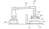
- FIG. 1 is a schematic diagram showing a work supply system according to a first embodiment of the invention.
- the work supply system 1 according to the first embodiment is, schematically, a work configured to be able to transport the top work Wt from the work W group loaded on the work table 10.
- a supply robot 100 is provided.
- the work supply robot 100 includes a robot hand 120 that holds the top work Wt.
- the work supply system 1 further includes a camera 50 for identifying the work W group loaded on the work table 10 and a control device 200 capable of controlling the work supply robot 100 and the camera 50 . Furthermore, the work supply system 1 according to the first embodiment may further include a processing machine such as a bending machine, and may constitute an automatic processing system for the work W together with the processing machine.
- a processing machine such as a bending machine
- the work supply robot 100 is arranged between the work table 10 and a transfer destination (for example, a processing machine) of the work W, holds the work W on the work table 10, and processes the work W. It is configured to be transported toward a transport destination such as a machine.
- a transfer destination for example, a processing machine
- the work supply robot 100 includes a movement mechanism 160 for moving the work supply robot 100, a robot hand 120 capable of holding a work W, and a robot hand 120. and an arm portion 140 that brings the .
- the moving mechanism 160 has a rail portion 160a laid on the floor surface, a base table 160b movable along the rail portion 160a, and a base table driving means (not shown) for driving the base table 160b. It is a so-called direct-acting mechanism, and is configured to move the work supply robot 100 on the floor based on a control signal from a robot control section 230 (described later) of the control device 200 . Since the moving mechanism 160 can employ various known configurations, detailed description thereof will be omitted.
- the arm portion 140 is a multi-joint arm having six control axes, and not only transports the work W from the work table 10, but also transports (carries in) the work W to a processing machine or the like. , assistance in processing (bending) of the work W, and transportation (unloading) of the product (bent product) from the processing machine or the like.
- the arm part 140 can employ various known configurations, detailed description thereof will be omitted.
- the arm unit 140 is not limited to the configuration of the multi-joint arm having the six control axes described above, and various known configurations can be arbitrarily adopted.
- FIG. 2 is a schematic diagram showing a robot hand of the workpiece supply robot according to the first embodiment.
- the robot hand 120 includes a hand main body 122 detachably attached to the tip of the arm portion 140, and a plurality of suction portions attached to the hand main body 122 and capable of holding a work W. 124.
- the hand main body 122 includes a mounting portion 122a detachably mounted on the distal end portion of the arm portion 140, a first support bar 122b coupled to the mounting portion 122a, and spaced apart in the longitudinal direction of the first support bar 122b. It has a plurality of second support bars 122c provided in parallel.
- the shape of the hand main body 122 is not limited to the illustrated example, and can be arbitrarily changed according to the shape of the work W and the like.
- the adsorption units 124 are attached to both ends of each second support bar 122c, and are connected to air suction sources (not shown) for sucking air via pipes.
- Each suction unit 124 has a flat suction pad at its lower end that can be suctioned (contacted) to the surface of the work W, and is loaded on the work mounting table 10 by the air suction force of the air suction source. It is configured to be attracted to the surface of the uppermost work Wt from the work W group. Since the robot hand 120 can employ various known configurations, detailed description thereof will be omitted. Further, the robot hand 120 is not limited to the suction method described above, and various known configurations can be arbitrarily adopted.
- the camera 50 has one lens and one image sensor, and as shown in FIG. , is arranged via a support member such as a camera stand 51 or the like.
- the camera 50 is arranged at a position that does not interfere with the workpiece supply robot 100, and is configured to photograph the group of workpieces W loaded on the workpiece mounting table 10 from above. It is
- the camera 50 is configured to supply captured image data to the image processing unit 250 of the control device 200, which will be described later.
- the camera 50 according to the first embodiment may be configured to directly output a digital signal (captured image data) from the camera 50 to the image processing unit 250, or an analog signal output from the camera 50 (captured image data). signal) may be converted into a digital signal (captured image data) by an A/D converter (not shown) or the like and output to the image processing unit 250 .
- the camera 50 is configured to be interlockable with lighting equipment L, which will be described later, so that the group of works W loaded on the work table 10 is illuminated with illumination light when the group of works W is photographed. According to such a configuration, there is an advantage that the edges of the group of works W are clarified, and the edges of the group of works W can be easily specified when specifying the outer shape and position of the group of works W.
- the work table 10 is provided with a magnet floater 20 at the end on the work supply robot 100 side.
- the magnet floater 20 loads the group of works W on the work table 10 with the end surfaces of the group of works W abutted against the abutting surface 22, the upper part of the group of works W can be floated by the magnetic force of the magnet. can.
- an end surface bar (not shown) and a plurality of LEDs (Light-Emitting Diodes) capable of irradiating the group of works W loaded with light are provided.
- a lighting installation L is provided.
- the work supply system 1 according to the first embodiment is configured such that the illumination facility L assists the identification of the work W by the camera 50 .
- the work table 10, the magnet floater 20, and the lighting equipment L can arbitrarily employ various known configurations, and thus detailed description thereof will be omitted.
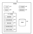
- FIG. 3 is a functional block diagram showing the control device according to the first embodiment.
- the control device 200 includes an input unit 210, a display unit 220, a robot control unit 230, a camera control unit 240, an image processing unit 250, and a storage unit 260, as shown in FIG. Also, the control device 200 is connected to the work supply robot 100 and the camera 50 by various known configurations.
- the input unit 210 is composed of input devices such as a keyboard, a mouse, a push button switch, a tact switch, and a key lock switch. In addition to the information input function, it is possible to perform operations such as selection of an NC control program, which will be described later, in the storage unit 260, and selection of a rotation center LC, which will be described later.
- the display unit 220 has a display as a display device, and in addition to the function of screen display normally required in the work supply system 1, for example, a selection screen for selecting an NC control program, and an imaging of the camera 50 An image, a screen for confirming the center of rotation LC, and the like are displayed. Also, the display unit 220 may be configured with a touch panel having the function of the input unit 210 . When the display unit 220 is configured by a touch panel, the user can input various information such as selection of an NC control program to the control device 200 by operating the display unit 220, for example.
- the configurations of the input unit 210 and the display unit 220 are not limited to the configurations described above. , input means, etc.), but not limited to these.
- the camera control unit 240 is configured to control the shooting operation of the camera 50 based on the shooting program stored in the storage unit 260. In addition, the camera control unit 240 performs control so that the irradiation of illumination light from the lighting equipment L is linked with the photographing of the camera 50 when the camera 50 photographs the group of works W. FIG.
- the image processing unit 250 detects edges of the outline of the group of works W loaded on the work table 10 based on the photographed image data supplied from the camera 50, and determines the position (x, y) of the group of works W from the edge detection result. It is configured to calculate information and supply the calculated position information to the robot control unit 230 . That is, the image processing unit 250 is configured to function as a work identification device that identifies the position of the top work Wt with high accuracy.
- the robot control unit 230 includes a transport control unit 232, a holding position specifying unit 234, a rectangle approximation unit 236, a nearest neighbor site specifying unit 238, and a rotation center specifying unit 239, as shown in FIG.
- the holding position specifying unit 234 performs holding position specifying processing for specifying the holding position of the workpiece W by the robot hand 120 of the work supply robot 100 .
- the holding position specifying unit 234 extracts the coordinate data of the workpiece W and the holding position of the robot hand 120 with respect to the workpiece W from the NC control program in the storage unit 260, which will be described later, and specifies the holding position.
- FIG. 4 is a schematic diagram showing the rectangle approximation processing of the workpiece according to the first embodiment.
- the rectangle approximation unit 236 is configured to execute rectangle approximation processing for approximating the shape of the work W so as to obtain a rectangle R that includes the work W, as shown in FIG.
- the rectangle approximation unit 236 extracts the contour of the work W from the coordinate data of the work W included in the NC control program in the storage unit 260, and extracts the point group from the set of coordinates representing the contour line. , and draw a rectangle R.
- the aspect ratio of the rectangle R varies depending on the shape of the work W on which the rectangle approximation process is performed, and the rectangle R is the smallest rectangle that encloses the work W.
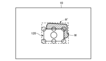
- FIG. 5 is a schematic diagram showing rectangle approximation processing for a workpiece and a robot hand according to the first embodiment. 5
- the rectangle approximation unit 236 In addition to the rectangle approximation process for approximating the shape of the work W so that , the rectangle approximation process for approximating a rectangle R' containing the work W and the robot hand 120 is executed. With such a configuration, it is possible to prevent the portion of the robot hand 120 protruding from the work W from getting into the work table 10 when the work W is peeled off.
- the nearest-neighbor part specifying unit 238 performs the nearest-neighbor part specifying process of specifying the part of the work W closest to the holding position of the robot hand 120 specified by the holding position specifying process of the holding position specifying unit 234 .
- the holding position of the robot hand 120 is specifically the end of the suction pad of the suction section 124 of the robot hand 120 .
- the part of the work W is specifically the side of the work W. As shown in FIG.
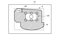
- FIG. 6A and 6B are schematic diagrams showing the process of specifying the nearest neighboring part of the workpiece according to the first embodiment.
- the nearest neighbor part identification process identifies the nearest neighbor side NS based on the rectangle R approximated by the rectangle approximation process of the rectangle approximation unit 236 .
- the nearest neighbor site identification unit 238 calculates the distances between the four sides forming the rectangle R and the ends of the suction pads of the suction unit 124 of the robot hand 120 that are closest to the respective sides, and calculates the distances. is specified as the nearest neighbor side NS.
- the distance between each side of the rectangle R and the end of the suction pad of the suction unit 124 is the distance along the direction orthogonal to each side of the rectangle R. Note that when the holding position of the robot hand 120 specified by the holding position specifying unit 234 is such that the robot hand 120 protrudes from the work W, the end of the suction pad of the suction unit 124 protruding from the work W is the closest part. Based on the end portion of the suction pad of the suction unit 124 in the work W that is excluded from the closest neighborhood portion identification processing of the identification unit 238 , the nearest neighborhood portion identification processing is performed.
- FIG. 7 is a schematic diagram showing the rotation center of the work according to the first embodiment.
- the rotation center identification unit 239 performs rotation center identification processing for identifying the side facing the nearest neighbor portion NS identified by the nearest neighborhood portion identification processing of the nearest neighborhood portion identification unit 238 as the rotation center LC. conduct.
- the nearest neighbor part NS specified by the nearest neighbor part specifying processing of the nearest neighbor part specifying unit 238 The side of the rectangle R' facing is specified as the center of rotation LC.
- FIG. 8 is a schematic diagram showing processing when there are a plurality of nearest neighboring parts of the workpiece according to the first embodiment.
- FIG. 9 is a schematic diagram showing processing when there is an obstacle around the workpiece according to the first embodiment.
- the rotation center specifying process of the rotation center specifying unit 239 is performed by specifying two or more nearest neighbor sides NS in the nearest neighbor part specifying process of the nearest neighbor part specifying unit 238. A side opposite to the side NS is identified as the center of rotation LC.
- the rotation center specifying process when there are two or more longest nearest neighbor sides NS, the The side to be rotated is specified as the center of rotation LC.
- the surrounding obstacle information is included, for example, in the NC control program of the storage unit 260, which will be described later, and is acquired as a priority longest nearest neighbor side identification parameter when two or more longest nearest neighbor sides NS are identified. , but not limited to.
- the transport control unit 232 is configured to enable CNC control (Computerized Numerical Control) of the work supply robot 100 , and is configured to be the maximum centered on the opposite side specified by the rotation center specifying process of the rotation center specifying unit 239 .
- CNC control Computerized Numerical Control
- a robot hand control process for separating the upper work Wt from the work W group is performed.
- the transport control unit 232 controls the load on the work mounting table 10 based on the NC control program stored in the storage unit 260. It is configured to control the moving mechanism 160 and the arm section 140 so that the robot hand 120 reaches the uppermost work Wt from the work W group. Further, when the robot hand 120 reaches the highest workpiece Wt, the transport control unit 232 controls the air suction source so that the robot hand 120 holds the highest workpiece Wt, and also controls the held highest workpiece Wt. The moving mechanism 160 and the arm unit 140 are controlled so that the workpiece Wt is lifted while rotating about the rotation center LC and transported to a transport destination such as a processing machine.
- the robot hand control processing of the transport control unit 232 is performed such that the uppermost work Wt is rotated around the opposing portion of the uppermost work Wt, and a predetermined waiting time (for example, 2 seconds) is applied to the uppermost work Wt. It is configured to hold the work Wt.
- the standby time is not limited to the example described above, and various arbitrary times can be adopted depending on the size of the work W and the like.
- the robot control unit 230 having the above configuration is configured so that the user can select whether or not to perform the peeling operation of rotating the uppermost work Wt around the rotation center LC.
- the robot control unit 230 is configured so that the user can change the standby time for holding the rotating state of the top workpiece Wt from the initial setting value.
- the robot control unit 230 is configured so that the user can change the rotation angle when rotating the top workpiece Wt from the initial set value.
- the robot control unit 230 is configured to display on the display unit 220 a manual adjustment screen for the user to confirm the above-described setting items and change the settings.
- the storage unit 260 assists the work supply robot 100 in carrying (carrying out) the work W from the work table 10, carrying (carrying in) the work W to a processing machine or the like, processing (bending) the work W, and Stores an NC control program for carrying out (carrying out) a product (bent product) from a processing machine or the like.
- the storage unit 260 also stores a shooting program for controlling the camera 50, an image processing program, and the like.
- the storage unit 260 stores a work supply program for causing the robot control unit 230 to control the work supply robot 100 .
- the work supply program includes a holding position specifying process for specifying the holding position of the robot hand 120 with respect to the work W, and a nearest neighbor part for specifying the part of the work W closest to the holding position of the robot hand 120 specified by the holding position specifying process.
- the robot control unit 230 is configured to execute a robot hand control process for separating the work Wt from the work W group.
- the control device 200 having the above configuration is configured to display on the display unit 220 a manual adjustment screen on which the user can select whether or not to perform the peeling operation for the top workpiece Wt.
- the control device 200 displays, on the manual adjustment screen, a standby time to hold the uppermost work Wt in a state in which it is rotated around the opposing portion of the uppermost work Wt, and a waiting time when the uppermost work Wt is rotated. Also display the rotation angle.
- the control device 200 having such a configuration allows the user to operate the input unit 210 or the display unit 220 configured by the touch panel of the control device 200 to determine whether or not to perform the peeling operation, the standby time, and the rotation angle. and can be manually changed from the initial setting state.
- the rotation center LC identified by the rotation center identification processing of the rotation center identification unit 239 can be manually changed. Specifically, the image of the highest workpiece Wt photographed by the camera 50 and the rectangles R and R' approximating the highest workpiece Wt are displayed on the manual adjustment screen of the display unit 220 .
- the rotation center LC identified by the rotation center identification unit 239 is highlighted on the rectangles R, R' in a color different from the other sides of the top workpiece Wt. Further, other sides of the uppermost workpiece Wt that can be selected by the user as the center of rotation LC are clearly indicated on the rectangles R, R' so that the user can identify them.
- the user can select another side of the top workpiece Wt as the rotation center LC.
- control device 200 optimizes the effectiveness of the peeling operation and the effect of the peeling operation based on the shape and size of the workpiece W, the shape and size of the robot hand 120, and the holding position of the robot hand 120. It may be configured to identify the parameters to be changed for the purpose and display them on the display unit 220 .
- FIG. 10 is a flow chart showing an example of a work supply method using the work supply system of the first embodiment.
- a series of work supply methods of the work supply system 1 described above will be described with reference to FIG.
- a series of work supply methods are executed while the work W is being loaded.
- the robot control unit 230 of the control device 200 reads from the storage unit 260 an NC control program for the work supply robot 100 to convey the work W.
- the holding position specifying unit 234 of the robot control unit 230 of the control device 200 specifies the holding position of the robot hand 120 of the work supply robot 100 for the uppermost work Wt of the work W group from the read NC control program.
- a specifying process is executed (S1 in FIG. 10: holding position specifying process step).
- the rectangle approximation section 236 of the robot control section 230 of the control device 200 executes the rectangle approximation process.
- the rectangle approximation unit 236 executes different rectangle approximation processes according to the holding position of the uppermost work Wt of the robot hand 120 of the work supply robot 100 specified by the holding position specifying process. Specifically, if the robot hand 120 does not protrude from the top work Wt (NO in S2 of FIG. 10), the rectangle approximation unit 236 aligns the top work Wt with a rectangle R that includes the top work Wt.
- a rectangle approximation process for approximating the shape of is executed (S3 in FIG. 10).
- a rectangle approximation process is further executed to approximate a rectangle R' that includes the top work Wt and the robot hand 120. (S5 in FIG. 10).
- the nearest neighbor part identification unit 238 of the robot control unit 230 of the control device 200 executes the nearest neighborhood part identification process based on the rectangle R approximated by the rectangle approximation process of the rectangle approximation unit 236 .
- the nearest-neighboring part identifying unit 238 selects the highest position closest to the end of the suction pad of the suction unit 124 of the robot hand 120 of the work supply robot 100 identified by the holding position specifying process of the holding position specifying unit 234 . (S4 in FIG. 10: nearest neighbor portion identification processing step).
- the rotation center specifying part 239 of the robot control part 230 of the control device 200 performs Execute the following process. That is, when there is one nearest neighbor side NS specified by the nearest neighbor part specifying unit 238 (NO in S6 of FIG. 10), the rotation center specifying unit 239 sets the side opposite to the nearest neighbor side NS to the rotation center LC. (S7 in FIG. 10: Rotation center identification processing step). If there are a plurality of nearest neighbor sides NS specified by nearest neighbor part specifying section 238 (YES in S6 of FIG. 10), rotation center specifying section 239 determines if there is one longest nearest neighbor side NS (see FIG. 10 NO in S11), the side facing the longest nearest neighbor side NS is specified as the rotation center LC (S12 in FIG. 10).
- the rotation center specifying unit 239 specifies, as the rotation center LC, the side facing the longest nearest neighbor side NS with an obstacle (end surface bar or magnet floater 20) around the top workpiece Wt. (S13 in FIG. 10).
- the control device 200 corrects the NC control program based on the captured image data supplied from the camera 50 . Simultaneously with or after the correction of the NC control program, the control device 200 displays the rotation center LC identified by the rotation center identification section 239 of the robot control section 230 on the display section 220 (S8 in FIG. 10). Specifically, the rotation center LC specified by the rotation center specifying unit 239 is highlighted on the rectangles R, R' approximating the highest workpiece Wt in a color different from the other sides of the highest workpiece Wt. . Other sides of the highest workpiece Wt that can be selected by the user as the center of rotation LC are also clearly indicated so that the user can identify them.
- control device 200 displays on the display unit 220 whether or not to perform the peeling operation of the top work Wt, the standby time for holding the top work Wt in a rotated state, and the rotation time of the top work Wt.
- a manual adjustment screen is displayed on which the user can manually change the rotation angle at the time of rotation from the initial setting state.
- the user confirms the center of rotation LC displayed on the display unit 220 of the control device 200 .
- the input unit 210 of the control device 200 or the touch panel of the control device 200 can be used.
- the display unit 220 that is displayed it is possible to select another side of the top workpiece Wt as the rotation center LC (S14 in FIG. 10).
- the transport control unit 232 of the robot control unit 230 of the control device 200 sets the side specified by the rotation center specifying unit 239 as the rotation center LC.
- a robot hand control process for separating the uppermost work Wt from the work W group is executed (robot hand control processing step).
- the transport control unit 232 executes a robot hand control process for separating the top workpiece Wt from the group of workpieces W with the side selected by the user as the center of rotation LC.
- the work supply robot 100 supplies the top work Wt from the work table 10 to the processing machine under the control of the transfer control unit 232 (S10 in FIG. 10).
- 11 to 13 are schematic diagrams showing the peeling operation of the uppermost work according to the first embodiment.
- the work supply robot 100 moves the robot hand 120 to the uppermost work Wt holding position by operating the arm section 140 and the moving mechanism 160 .
- the robot hand 120 holds the uppermost work Wt by causing the suction pads of the suction unit 124 to adhere to the surface of the uppermost work Wt by the suction force of the air suction source.
- the work supply robot 100 holding the uppermost work Wt is rotated by the side of the uppermost work Wt specified by the rotation center specifying unit 239 of the robot control unit 230 of the control device 200 or by the user manually.
- the top work Wt is peeled off from the group of works W with the side of the top work Wt selected as the center of rotation LC.
- the workpiece supply robot 100 holds the highest workpiece Wt for a predetermined standby time in the posture shown in FIG. After a predetermined waiting time has passed, the work supply robot 100 separates the side of the uppermost work Wt specified or selected as the center of rotation LC from the group of works W, and places it on the work table 10, as shown in FIG. The uppermost work Wt is held so as to be substantially horizontal with respect to it. After that, the work supply robot 100 supplies the top work Wt to the processing machine.
- a series of operations of the work supply method by the work supply system 1 according to the first embodiment are executed by the above steps.
- the work supply system 1 includes the work supply robot 100 configured to be capable of transporting the top work Wt from the work W group loaded on the work table 10, and the robot
- the work supply robot 100 includes a robot hand 120 that holds the uppermost work Wt. , the nearest neighbor portion identifying process for identifying the portion (side) of the workpiece W closest to the holding position of the robot hand 120 identified by the holding position identifying processing; A rotation center identifying process for identifying the opposite part (side) facing the side NS) as the rotation center LC, and a robot that separates the uppermost workpiece Wt from the group of workpieces W centering on the opposed part identified by the rotation center identifying process. hand control processing.
- the work supply system 1 selects the rotation center LC according to the holding position of the robot hand 120 with respect to the work W, and moves the top work Wt to the work W. Since the workpieces W are obliquely lifted and separated from the group, there is an advantage that only the uppermost workpiece Wt can be held regardless of the placement location of the workpieces W on the workpiece mounting table 10 and the shape of the workpieces W. Furthermore, the present inventors found that the closer the end of the suction pad of the suction unit 124 of the robot hand 120 and the end of the workpiece W, the higher the success rate of picking up only the uppermost workpiece Wt from the group of workpieces W. I found a new finding to go up.
- the rotation center LC is separated from the holding position of the robot hand 120. That is, since the end of the suction pad and the end of the work W (nearest neighbor side NS) are close, there is an advantage that only the top work Wt can be separated from the work W group more reliably.
- the nearest neighboring portion and the facing portion of the work W are the sides of the work W.
- the rotation center identification control process is performed when two or more nearest neighbor portions (nearest neighbor sides NS) are identified in the nearest neighborhood portion identification processing.
- the uppermost workpiece Wt is separated from the group of workpieces W with the opposite part (side) facing the part (nearest neighbor side NS) as the center of rotation LC.
- the uppermost workpiece Wt is separated from the group of workpieces W with the opposite portion (side) facing the workpiece W as the center of rotation LC.
- the robot control unit 230 is configured to further execute a rectangle approximation process for approximating the shape of the work W so as to obtain a rectangle R that includes the work W.
- the part identification process identifies the nearest neighboring part based on the rectangle R approximated by the rectangle approximation process.
- the robot hand control process is performed in a state in which the top work Wt is rotated around the opposing portion of the top work Wt, and the top work Wt is rotated for a predetermined standby time. It is configured to hold the work Wt. With such a configuration, even if the work W directly below sticks to the work Wt of the highest level, the work W directly below is separated from the work Wt of the highest level by its own weight. The advantage is that only one work Wt can be separated from the work W group.
- the nearest neighbor part specifying unit 238 specifies the part of the work W closest to the holding position of the robot hand 120 specified by the holding position specifying process of the holding position specifying unit 234. Performs the nearest neighbor site identification process.
- the holding position of the robot hand 120 is specifically the end of the suction pad of the suction section 124 of the robot hand 120 .
- the part of the work W is specifically the corner of the work W. As shown in FIG.
- the nearest neighbor part identification process identifies the nearest neighbor corner NC based on the rectangle R approximated by the rectangle approximation process of the rectangle approximation unit 236 .
- the nearest neighbor site identification unit 238 calculates the distances between the four corners forming the rectangle R and the ends of the suction pads of the suction unit 124 of the robot hand 120 that are closest to the respective corners, and calculates the distances. is the shortest distance Lmin as the nearest neighbor angle NC.
- FIG. 15 is a schematic diagram showing the rotation center of the work according to the second embodiment.
- the transport control unit 232 sets the uppermost work Wt as the work Wt with the angle opposite the nearest neighbor angle NC specified by the nearest neighbor part specifying process of the nearest neighbor part specifying unit 238 as the rotation center LC.
- a robot hand control process for separating from the W group is performed.
- the robot hand control process of the transport control unit 232 is performed in a state in which the nearest neighbor angle NC of the uppermost work Wt is separated from the work W group and the corner opposite to the nearest neighbor angle NC is not separated from the work W group. It is configured to hold the highest work Wt for a predetermined waiting time (for example, 2 seconds).
- the standby time is not limited to the example described above, and various arbitrary times can be adopted depending on the size of the work W and the like.
- the work supply system 1' selects the rotation center LC according to the holding position of the robot hand 120, and selects the top work Wt as the work, as in the first embodiment. Since it is separated from the W group, there is an advantage that only the uppermost work Wt can be held regardless of the stacking position of the W group.
- the nearest neighboring portion and the facing portion of the work W are the corners of the work W.
- the robot control unit 230 further executes rectangle approximation processing for approximating the shape of the work W to a rectangle R that includes the work W.
- the nearest neighbor part identifying process is configured to identify the nearest neighbor part (nearest neighbor angle NC) based on the rectangle R approximated by the rectangle approximation process.
- NC nearest neighbor angle
- the robot hand control processing is such that the nearest neighbor portion (the nearest neighbor angle NC) of the uppermost work Wt is separated from the work W.
- the workpiece Wt of the highest rank is held for a predetermined standby time.
- the nearest neighbor portion and the facing portion of the work W are described as sides of the work W, and in the above-described second embodiment, the nearest neighbor portion and the facing portion of the work W are , are the corners of the work W, but the present invention is not limited to this.
- the nearest neighbor portion and opposing portion of the work W may be arbitrary portions other than the sides or corners of the work W.
- the rotation center specifying process is performed when two or more nearest neighbor parts (nearest neighbor side NS) are specified in the nearest neighbor part specifying process.
- the uppermost work Wt is peeled off from the group of works W with the opposing portion (side) opposed to the center of rotation LC as the center of rotation LC, the present invention is not limited to this.
- the uppermost workpiece Wt may be separated from the group of workpieces W with the opposite portion (side) facing another nearest neighbor portion (closest neighbor side NS) as the center of rotation LC.
- the rotation center identification process is performed to face the longest and nearest neighbor portion (nearest neighbor side NS) having an obstacle in its periphery.
- the uppermost work Wt is separated from the group of works W with the site (side) as the center of rotation LC, the present invention is not limited to this.
- the uppermost workpiece Wt may be separated from the group of workpieces W with the opposite portion (side) facing another nearest neighbor portion (closest neighbor side NS) as the center of rotation LC.
- the robot control unit 230 is configured to further execute a rectangle approximation process for approximating the shape of the workpiece W so as to obtain a rectangle R that includes the workpiece W.
- the identification processing has been described as identifying the nearest neighboring site based on the rectangle R approximated by the rectangle approximation processing, the identification processing is not limited to this.
- the robot control unit 230 may perform the nearest neighboring part identification process based on the shape of the workpiece W without performing the rectangle approximation process.
- the robot hand control process is performed by rotating the uppermost work Wt around the opposing portion of the uppermost work Wt, and holding the uppermost work Wt for a predetermined waiting time.
- the opposing portion (side, corner) of the uppermost work Wt may be separated from the work W group immediately after the state described above.
- the holding position of the robot hand 120 is described as being the end of the suction pad of the suction section 124 of the robot hand 120, but is not limited to this.
- the central portion of the suction pad 124 or the end portion of the hand main body 122 of the robot hand 120 may be used.
- the work W group is mounted on the mounting table 10 after the rotation center LC is specified.
- the group of works W may be mounted on the mounting table 10 before or during the identification of the rotation center LC.
Landscapes
- Engineering & Computer Science (AREA)
- Mechanical Engineering (AREA)
- Robotics (AREA)
- Health & Medical Sciences (AREA)
- General Health & Medical Sciences (AREA)
- Orthopedic Medicine & Surgery (AREA)
- Manipulator (AREA)
- De-Stacking Of Articles (AREA)
- Specific Conveyance Elements (AREA)
Abstract
Description
図1は、本発明の第1実施形態に係るワーク供給システムを示す概略図である。
図1に示すように、第1実施形態に係るワーク供給システム1は、概略的には、ワーク載置台10上に積載されたワークW群から最上位のワークWtを搬送可能に構成されたワーク供給ロボット100を備える。ワーク供給ロボット100は、最上位のワークWtを保持するロボットハンド120を含んでいる。
ワーク供給ロボット100は、ワーク載置台10と、ワークWの搬送先(例えば、加工機等)との間に配置されており、ワーク載置台10上でワークWを保持し、そのワークWを加工機等の搬送先に向けて搬送するように構成されている。
ロボットハンド120は、図2に示すように、アーム部140の先端部に着脱可能に装着されるハンド本体122と、ハンド本体122に取り付けられ、ワークWを保持可能に構成された複数の吸着部124とを有している。ハンド本体122は、アーム部140の先端部に着脱可能に装着される装着部122aと、装着部122aに結合された第1支持バー122bと、第1支持バー122bにその長手方向に間隔を置いて設けられた複数の第2支持バー122cとを有している。なお、ハンド本体122の形状は、図示の例に限定されず、ワークWの形状等に応じて任意に変更することが可能である。
カメラ50は、レンズ及びイメージセンサが1つずつ配されており、図1に示すように、少なくともワーク載置台10の全体又は一部を撮影範囲として撮影可能となるよう、ワーク載置台10の上部に、カメラスタンド51等の支持部材を介して配置されている。第1実施形態において、カメラ50は、図1に示すように、ワーク供給ロボット100と干渉しない位置に配置されており、ワーク載置台10に積載されたワークW群を上方から撮影するように構成されている。
ワーク載置台10は、図1に示すように、ワーク供給ロボット100側の端部にマグネットフロータ20が設けられている。マグネットフロータ20は、ワークW群の端面を突当て面22に突き当てた状態で、ワーク載置台10に積載すると、マグネットの磁力によってワークW群のうちの上部側のワークWを浮上させることができる。
図3は、第1実施形態に係る制御装置を示す機能ブロック図である。
制御装置200は、図3に示すように、入力部210と、表示部220と、ロボット制御部230と、カメラ制御部240と、画像処理部250と、記憶部260とを含む。また、制御装置200は、種々の公知の構成によりワーク供給ロボット100及びカメラ50と接続している。
矩形近似部236は、図4に示すように、ワークWを包含する矩形RとなるようにワークWの形状を近似する矩形近似処理を実行するよう構成されている。具体的には、矩形近似部236は、記憶部260のNC制御プログラムに含まれるワークWの座標データからワークWの輪郭を抽出し、輪郭線を表す点群の座標の集まりから、その点群の外接矩形の座標を計算し、矩形Rを描画する。矩形Rのアスペクト比は、矩形近似処理を実行するワークWの形状によって異なり、矩形Rは、ワークWを内包する最小の矩形である。
また、矩形近似部236は、図5に示すように、保持位置特定部234が特定したロボットハンド120の保持位置が、ロボットハンド120がワークWからはみ出ていた場合、ワークWを包含する矩形RとなるようにワークWの形状を近似する矩形近似処理に加え、ワークWとロボットハンド120を包含する矩形R′に近似する矩形近似処理を実行する。このような構成を備えることにより、ワークWを剥離させる際に、ロボットハンド120のワークWからはみ出ている部分がワーク載置台10にめり込むことを防ぐことができる。
最近傍部位特定処理は、図6に示すように、矩形近似部236の矩形近似処理により近似された矩形Rに基づいて最近傍辺(nearest neibour side)NSを特定する。具体的には、最近傍部位特定部238は、矩形Rを構成する4つの辺と、各辺に最も近いロボットハンド120の吸着部124の吸着パッドの端部との距離を計算し、その距離が最短距離Lminとなる辺を最近傍辺NSとして特定する。本明細書において矩形Rの各辺と吸着部124の吸着パッドの端部との距離は、矩形Rの各辺と直交する方向に沿う距離である。なお、保持位置特定部234が特定したロボットハンド120の保持位置が、ロボットハンド120がワークWからはみ出ていた場合、ワークWからはみ出している吸着部124の吸着パッドの端部は、最近傍部位特定部238の最近傍部位特定処理から除外され、ワークW内の吸着部124の吸着パッドの端部に基づいて最近傍部位特定処理を行う。
回転中心特定部239は、図7に示すように、最近傍部位特定部238の最近傍部位特定処理により特定された最近傍部位NSと対向する辺を回転中心LCとして特定する回転中心特定処理を行う。また、保持位置特定部234が特定したロボットハンド120の保持位置が、ロボットハンド120がワークWからはみ出ていた場合、最近傍部位特定部238の最近傍部位特定処理により特定された最近傍部位NSと対向する矩形R′の辺を回転中心LCとして特定する。
図9は、第1実施形態に係るワークの周辺に障害物がある場合の処理を示す概略図である。
回転中心特定部239の回転中心特定処理は、図8に示すように、最近傍部位特定部238の最近傍部位特定処理において、2以上の最近傍辺NSを特定した場合には、最長最近傍辺NSと対向する辺を回転中心LCとして特定する。また、回転中心特定処理は、図9に示すように、最長最近傍辺NSが2以上ある場合、周辺に障害物(例えば、端面バー及びマグネットフロータ20等)がある最長最近傍辺NSと対向する辺を回転中心LCとして特定する。周辺の障害物情報は、例えば、後述する記憶部260のNC制御プログラムに含まれており、最長最近傍辺NSが2以上特定された場合に、優先最長最近傍辺特定パラメータとして取得されるが、これに限定されない。
図10は、第1実施形態のワーク供給システムを用いたワーク供給方法の一例を示すフローチャートである。
図10を参照して、以上説明したワーク供給システム1の一連のワーク供給方法について説明する。一連のワーク供給方法は、ワークWのローディング中に実行されるものである。具体的には、まず、制御装置200のロボット制御部230は、ワーク供給ロボット100がワークWを搬送するためのNC制御プログラムを記憶部260から読み出す。制御装置200のロボット制御部230の保持位置特定部234は、読み出されたNC制御プログラムからワークW群の最上位のワークWtに対するワーク供給ロボット100のロボットハンド120の保持位置を特定する保持位置特定処理を実行する(図10のS1:保持位置特定処理工程)。
ワーク供給ロボット100は、図11に示すように、アーム部140及び移動機構160が動作することでロボットハンド120が最上位のワークWtの保持位置に移動する。ロボットハンド120は、吸着部124の吸着パッドがエア吸引源による吸引力によって最上位のワークWtの表面に吸着することで最上位のワークWtを保持する。最上位のワークWtを保持したワーク供給ロボット100は、図12に示すように、制御装置200のロボット制御部230の回転中心特定部239が特定した最上位のワークWtの辺、又はユーザが手動で選択した最上位のワークWtの辺を回転中心LCとして最上位のワークWtをワークW群から剥離させる。ワーク供給ロボット100は、図12の姿勢、すなわち、最上位のワークWtを最上位のワークWtの対向部位を中心として回転させた状態で所定の待機時間最上位のワークWtを保持する。所定の待機時間の経過後、ワーク供給ロボット100は、図13に示すように、回転中心LCとして特定又は選択された最上位のワークWtの辺をワークW群から離間させ、ワーク載置台10に対してほぼ水平になるように最上位のワークWtを保持する。その後、ワーク供給ロボット100は、加工機へ最上位のワークWtを供給する。以上の工程により第1実施形態に係るワーク供給システム1によるワーク供給方法の一連の動作が実行される。
以上説明したように、第1実施形態に係るワーク供給システム1は、ワーク載置台10上に積載されたワークW群から最上位のワークWtを搬送可能に構成されたワーク供給ロボット100と、ロボット制御部230とを備え、ワーク供給ロボット100は、最上位のワークWtを保持するロボットハンド120を含み、ロボット制御部230は、ワークWに対するロボットハンド120の保持位置を特定する保持位置特定処理と、保持位置特定処理により特定されたロボットハンド120の保持位置に最も近いワークWの部位(辺)を特定する最近傍部位特定処理と、最近傍部位特定処理により特定された最近傍部位(最近傍辺NS)と対向する対向部位(辺)を回転中心LCとして特定する回転中心特定処理と、回転中心特定処理により特定された対向部位を中心として最上位のワークWtをワークW群から剥離させるロボットハンド制御処理とを行う。
次に、第2実施形態に係るワーク供給システム1′について説明する。なお、第2実施形態において、第1実施形態と同じ機能を果たす部分には同じ符号を付し、重複する説明は省略する。
最近傍部位特定処理は、図14に示すように、矩形近似部236の矩形近似処理により近似された矩形Rに基づいて最近傍角(nearest neibour corner)NCを特定する。具体的には、最近傍部位特定部238は、矩形Rを構成する4つの角と、各角に最も近いロボットハンド120の吸着部124の吸着パッドの端部との距離を計算し、その距離が最短距離Lminとなる角を最近傍角NCとして特定する。
搬送制御部232は、図15に示すように、最近傍部位特定部238の最近傍部位特定処理により特定された最近傍角NCと対向する角を回転中心LCとして、最上位のワークWtをワークW群から剥離させるロボットハンド制御処理を行う。
以上説明したように、第2実施形態に係るワーク供給システム1′は、第1実施形態と同様に、ロボットハンド120の保持位置に応じて回転中心LCを選択し、最上位のワークWtをワークW群から剥離させるため、ワークW群の積載位置にかかわらず最上位のワークWtのみを保持できるという利点を有している。
以上、本発明の好適な実施形態について説明したが、本発明の技術的範囲は、第1実施形態及び第2実施形態に記載の範囲には限定されない。上述した実施形態には、多様な変更又は改良を加えることが可能である。
10 ワーク載置台
20 マグネットフロータ
22 突き当て面
50 カメラ
51 カメラスタンド
100 ワーク供給ロボット
120 ロボットハンド
122 ハンド本体
122a 装着部
122b 第1支持バー
122c 第2支持バー
124 吸着部
140 アーム部
160 移動機構
160a レール部
160b ベース台
200 制御装置
210 入力部
220 表示部
230 ロボット制御部
232 搬送制御部
234 保持位置特定部
236 矩形近似部
238 最近傍部位特定部
239 回転中心特定部
240 カメラ制御部
250 画像処理部
260 記憶部
L 照明設備
LC 回転中心
Lmin 最短距離
NC 最近傍角(最近傍部位)
NS 最近傍辺(最近傍部位)
R,R′ 矩形
W ワーク
Wt 最上位のワーク
Claims (9)
- ワーク載置台上に積載されたワーク群から最上位のワークを搬送可能に構成されたワーク供給ロボットと、
ロボット制御部と
を備え、
前記ワーク供給ロボットは、前記最上位のワークを保持するロボットハンドを含み、
前記ロボット制御部は、
前記ワークに対する前記ロボットハンドの保持位置を特定する保持位置特定処理と、
前記保持位置特定処理により特定された前記ロボットハンドの前記保持位置に最も近いワークの部位を特定する最近傍部位特定処理と、
前記最近傍部位特定処理により特定された最近傍部位と対向する対向部位を回転中心として特定する回転中心特定処理と、
前記回転中心特定処理により特定された前記対向部位を中心として前記最上位のワークを前記ワーク群から剥離させるロボットハンド制御処理と
を行う
ワーク供給システム。 - 前記ワークの前記最近傍部位及び前記対向部位は、前記ワークの辺である
請求項1に記載のワーク供給システム。 - 前記回転中心特定処理は、前記最近傍部位特定処理において、2以上の最近傍部位を特定した場合には、最長最近傍部位と対向する対向部位を回転中心として特定する
請求項1又は2に記載のワーク供給システム。 - 前記回転中心特定処理は、前記最長最近傍部位が2以上ある場合、周辺に障害物がある前記最長最近傍部位と対向する対向部位を回転中心として特定する
請求項3に記載のワーク供給システム。 - 前記ワークの前記最近傍部位及び前記対向部位は、前記ワークの角である
請求項1に記載のワーク供給システム。 - 前記ロボット制御部は、前記ワークを包含する矩形となるよう前記ワークの形状を近似する矩形近似処理を更に実行するよう構成され、
前記最近傍部位特定処理は、前記矩形近似処理により近似された矩形に基づいて最近傍部位を特定する
請求項1~5のいずれか1項に記載のワーク供給システム。 - 前記ロボットハンド制御処理は、前記最上位のワークを前記最上位のワークの前記対向部位を中心として回転させた状態において、所定の待機時間前記最上位のワークを保持するよう構成されている
請求項1~6のいずれか1項に記載のワーク供給システム。 - ワークに対するロボットハンドの保持位置を特定する保持位置特定処理工程と、
前記保持位置特定処理により特定された前記ロボットハンドの前記保持位置に最も近いワークの部位を特定する最近傍部位特定処理工程と、
前記最近傍部位特定処理により特定された最近傍部位と対向する対向部位を回転中心として特定する回転中心特定処理工程と、
前記回転中心特定処理により特定された前記対向部位を中心として前記最上位のワークを前記ワーク群から剥離させるロボットハンド制御処理工程と
を備える
ワーク供給方法。 - ワークに対するロボットハンドの保持位置を特定する保持位置特定処理と、
前記保持位置特定処理により特定された前記ロボットハンドの前記保持位置に最も近いワークの部位を特定する最近傍部位特定処理と、
前記最近傍部位特定処理により特定された最近傍部位と対向する対向部位を回転中心として特定する回転中心特定処理と、
前記回転中心特定処理により特定された前記対向部位を中心として前記最上位のワークを前記ワーク群から剥離させるロボットハンド制御処理と
をロボット制御部に実行させる
ワーク供給プログラム。
Priority Applications (3)
| Application Number | Priority Date | Filing Date | Title |
|---|---|---|---|
| EP22889809.4A EP4427891A4 (en) | 2021-11-04 | 2022-10-21 | WORKPIECE FEEDING SYSTEM, WORKPIECE FEEDING METHOD, AND WORKPIECE FEEDING PROGRAM |
| US18/699,270 US20240408761A1 (en) | 2021-11-04 | 2022-10-21 | Workpiece supply system, workpiece supply method, and workpiece supply program |
| CN202280073046.9A CN118215631A (zh) | 2021-11-04 | 2022-10-21 | 工件供给系统、工件供给方法以及工件供给程序 |
Applications Claiming Priority (2)
| Application Number | Priority Date | Filing Date | Title |
|---|---|---|---|
| JP2021180533A JP7689904B2 (ja) | 2021-11-04 | 2021-11-04 | ワーク供給システム、ワーク供給方法及びワーク供給プログラム |
| JP2021-180533 | 2021-11-04 |
Publications (1)
| Publication Number | Publication Date |
|---|---|
| WO2023079989A1 true WO2023079989A1 (ja) | 2023-05-11 |
Family
ID=86240999
Family Applications (1)
| Application Number | Title | Priority Date | Filing Date |
|---|---|---|---|
| PCT/JP2022/039385 Ceased WO2023079989A1 (ja) | 2021-11-04 | 2022-10-21 | ワーク供給システム、ワーク供給方法及びワーク供給プログラム |
Country Status (5)
| Country | Link |
|---|---|
| US (1) | US20240408761A1 (ja) |
| EP (1) | EP4427891A4 (ja) |
| JP (1) | JP7689904B2 (ja) |
| CN (1) | CN118215631A (ja) |
| WO (1) | WO2023079989A1 (ja) |
Families Citing this family (1)
| Publication number | Priority date | Publication date | Assignee | Title |
|---|---|---|---|---|
| CN120281415A (zh) * | 2024-01-08 | 2025-07-08 | 宁波环球广电科技有限公司 | 参数调整方法及系统 |
Citations (9)
| Publication number | Priority date | Publication date | Assignee | Title |
|---|---|---|---|---|
| JPH0243143A (ja) * | 1988-08-04 | 1990-02-13 | Asahi Glass Co Ltd | 板材吸着ハンド及びこれを用いた採板移載装置 |
| US5033730A (en) * | 1990-02-28 | 1991-07-23 | Sri International | Variable position vacuum article pickup apparatus |
| JPH0538521A (ja) | 1991-04-17 | 1993-02-19 | Daikin Ind Ltd | プレスブレーキシステムにおけるワーク取扱装置 |
| JP2002361583A (ja) * | 2001-06-11 | 2002-12-18 | Amada Co Ltd | 重ね板材の一枚取り装置 |
| JP2004175541A (ja) * | 2002-11-28 | 2004-06-24 | Sanyo Electric Co Ltd | 分離装置 |
| JP2016135512A (ja) * | 2015-01-23 | 2016-07-28 | 東レエンジニアリング株式会社 | 板状物移載装置および板状物移載方法 |
| JP2018120388A (ja) | 2017-01-25 | 2018-08-02 | 株式会社アマダホールディングス | ワーク検出装置及び方法 |
| JP2020163553A (ja) * | 2019-03-29 | 2020-10-08 | 株式会社フジタ | ボードのピックアップ方法及びボードのピックアップ装置 |
| CN211643899U (zh) * | 2020-02-24 | 2020-10-09 | 张云强 | 一种家具装饰面板生产用推板上料装置 |
Family Cites Families (5)
| Publication number | Priority date | Publication date | Assignee | Title |
|---|---|---|---|---|
| JP4302160B2 (ja) * | 2007-09-12 | 2009-07-22 | ファナック株式会社 | ロボットによるパレタイジング作業のためのロボットプログラミング装置 |
| US9315344B1 (en) * | 2012-07-20 | 2016-04-19 | Amazon Technologies, Inc. | Container stacking configurations |
| US9682481B2 (en) * | 2015-10-26 | 2017-06-20 | X Development Llc | Communication of information regarding a robot using an optical identifier |
| US10124489B2 (en) * | 2016-02-26 | 2018-11-13 | Kinema Systems Inc. | Locating, separating, and picking boxes with a sensor-guided robot |
| EP3946834B1 (en) * | 2019-03-27 | 2024-01-10 | Boston Dynamics, Inc. | Robot and method for palletizing boxes |
-
2021
- 2021-11-04 JP JP2021180533A patent/JP7689904B2/ja active Active
-
2022
- 2022-10-21 CN CN202280073046.9A patent/CN118215631A/zh active Pending
- 2022-10-21 WO PCT/JP2022/039385 patent/WO2023079989A1/ja not_active Ceased
- 2022-10-21 EP EP22889809.4A patent/EP4427891A4/en active Pending
- 2022-10-21 US US18/699,270 patent/US20240408761A1/en active Pending
Patent Citations (9)
| Publication number | Priority date | Publication date | Assignee | Title |
|---|---|---|---|---|
| JPH0243143A (ja) * | 1988-08-04 | 1990-02-13 | Asahi Glass Co Ltd | 板材吸着ハンド及びこれを用いた採板移載装置 |
| US5033730A (en) * | 1990-02-28 | 1991-07-23 | Sri International | Variable position vacuum article pickup apparatus |
| JPH0538521A (ja) | 1991-04-17 | 1993-02-19 | Daikin Ind Ltd | プレスブレーキシステムにおけるワーク取扱装置 |
| JP2002361583A (ja) * | 2001-06-11 | 2002-12-18 | Amada Co Ltd | 重ね板材の一枚取り装置 |
| JP2004175541A (ja) * | 2002-11-28 | 2004-06-24 | Sanyo Electric Co Ltd | 分離装置 |
| JP2016135512A (ja) * | 2015-01-23 | 2016-07-28 | 東レエンジニアリング株式会社 | 板状物移載装置および板状物移載方法 |
| JP2018120388A (ja) | 2017-01-25 | 2018-08-02 | 株式会社アマダホールディングス | ワーク検出装置及び方法 |
| JP2020163553A (ja) * | 2019-03-29 | 2020-10-08 | 株式会社フジタ | ボードのピックアップ方法及びボードのピックアップ装置 |
| CN211643899U (zh) * | 2020-02-24 | 2020-10-09 | 张云强 | 一种家具装饰面板生产用推板上料装置 |
Also Published As
| Publication number | Publication date |
|---|---|
| US20240408761A1 (en) | 2024-12-12 |
| JP7689904B2 (ja) | 2025-06-09 |
| EP4427891A1 (en) | 2024-09-11 |
| CN118215631A (zh) | 2024-06-18 |
| EP4427891A4 (en) | 2025-03-05 |
| JP2023069004A (ja) | 2023-05-18 |
Similar Documents
| Publication | Publication Date | Title |
|---|---|---|
| US6135854A (en) | Automatic workpiece transport apparatus for double-side polishing machine | |
| JP2006035397A (ja) | 搬送ロボットシステム | |
| JP2010005769A (ja) | デパレタイズ装置および方法 | |
| WO2021053750A1 (ja) | 作業ロボットおよび作業システム | |
| JP2003172605A (ja) | 物品位置認識装置 | |
| WO2023079989A1 (ja) | ワーク供給システム、ワーク供給方法及びワーク供給プログラム | |
| JP4769232B2 (ja) | 実装機および部品吸着装置 | |
| WO2013118175A1 (ja) | 加工システム及び制御方法 | |
| KR20190103260A (ko) | 반송 시스템 및 그 운전 방법 | |
| JP7261644B2 (ja) | ボードのピックアップ方法及びボードのピックアップ装置 | |
| JP2007237394A (ja) | ワーク位置決め装置 | |
| JP7495864B2 (ja) | ワーク搬送システム及びワーク搬送方法 | |
| JP2018126794A (ja) | ワーク搬送制御装置、ワーク検出方法、及び、ワーク供給装置 | |
| WO2022137917A1 (ja) | 基板搬送ロボットの制御装置及び関節モータの制御方法 | |
| JPH06345270A (ja) | 荷卸し装置 | |
| JP2004106079A (ja) | ワーク位置決め装置 | |
| JP2917296B2 (ja) | 視覚機能付作業装置 | |
| JPS6265436A (ja) | ダイボンダにおけるウエハ−位置制御方法 | |
| JPH1120948A (ja) | ワーク搬送制御装置 | |
| JP2023081152A (ja) | 産業用ロボットおよび産業用ロボットの教示方法 | |
| JP3193414B2 (ja) | マニピュレータ制御装置及び座標補正方法 | |
| JPH04372389A (ja) | ワーク取上げハンド | |
| JP2002241078A (ja) | コンテナクレーンの着床目標設定装置 | |
| JP4483818B2 (ja) | ワーク移し替え方法、ワーク移し替え装置及びワーク移し替えシステム | |
| JP2856269B2 (ja) | 物品移載装置 |
Legal Events
| Date | Code | Title | Description |
|---|---|---|---|
| 121 | Ep: the epo has been informed by wipo that ep was designated in this application |
Ref document number: 22889809 Country of ref document: EP Kind code of ref document: A1 |
|
| WWE | Wipo information: entry into national phase |
Ref document number: 18699270 Country of ref document: US |
|
| WWE | Wipo information: entry into national phase |
Ref document number: 202280073046.9 Country of ref document: CN |
|
| WWE | Wipo information: entry into national phase |
Ref document number: 2022889809 Country of ref document: EP |
|
| NENP | Non-entry into the national phase |
Ref country code: DE |
|
| ENP | Entry into the national phase |
Ref document number: 2022889809 Country of ref document: EP Effective date: 20240604 |