WO2023080203A1 - 状態監視装置及び状態監視方法 - Google Patents
状態監視装置及び状態監視方法 Download PDFInfo
- Publication number
- WO2023080203A1 WO2023080203A1 PCT/JP2022/041201 JP2022041201W WO2023080203A1 WO 2023080203 A1 WO2023080203 A1 WO 2023080203A1 JP 2022041201 W JP2022041201 W JP 2022041201W WO 2023080203 A1 WO2023080203 A1 WO 2023080203A1
- Authority
- WO
- WIPO (PCT)
- Prior art keywords
- current
- data
- temperature
- monitoring device
- basic
- Prior art date
- Legal status (The legal status is an assumption and is not a legal conclusion. Google has not performed a legal analysis and makes no representation as to the accuracy of the status listed.)
- Ceased
Links
Images





Classifications
-
- B—PERFORMING OPERATIONS; TRANSPORTING
- B25—HAND TOOLS; PORTABLE POWER-DRIVEN TOOLS; MANIPULATORS
- B25J—MANIPULATORS; CHAMBERS PROVIDED WITH MANIPULATION DEVICES
- B25J9/00—Program-controlled manipulators
- B25J9/16—Program controls
- B25J9/1674—Program controls characterised by safety, monitoring, diagnostic
-
- G—PHYSICS
- G05—CONTROLLING; REGULATING
- G05B—CONTROL OR REGULATING SYSTEMS IN GENERAL; FUNCTIONAL ELEMENTS OF SUCH SYSTEMS; MONITORING OR TESTING ARRANGEMENTS FOR SUCH SYSTEMS OR ELEMENTS
- G05B23/00—Testing or monitoring of control systems or parts thereof
- G05B23/02—Electric testing or monitoring
-
- G—PHYSICS
- G05—CONTROLLING; REGULATING
- G05B—CONTROL OR REGULATING SYSTEMS IN GENERAL; FUNCTIONAL ELEMENTS OF SUCH SYSTEMS; MONITORING OR TESTING ARRANGEMENTS FOR SUCH SYSTEMS OR ELEMENTS
- G05B2219/00—Program-control systems
- G05B2219/30—Nc systems
- G05B2219/37—Measurements
- G05B2219/37384—Change of actuator current
-
- G—PHYSICS
- G05—CONTROLLING; REGULATING
- G05B—CONTROL OR REGULATING SYSTEMS IN GENERAL; FUNCTIONAL ELEMENTS OF SUCH SYSTEMS; MONITORING OR TESTING ARRANGEMENTS FOR SUCH SYSTEMS OR ELEMENTS
- G05B2219/00—Program-control systems
- G05B2219/30—Nc systems
- G05B2219/37—Measurements
- G05B2219/37431—Temperature
Definitions
- the present disclosure mainly relates to a state monitoring device that monitors the state of a robot and supports maintenance of the robot.
- Patent Document 1 discloses a robot controller.
- data in the robot controller can be saved externally and analyzed by an analysis device.
- Patent Document 1 The robot data analyzed in Patent Document 1 may include data that is affected by temperature. However, Patent Literature 1 does not describe at all how to suppress the influence of temperature change on data.
- the present disclosure has been made in view of the above circumstances, and its main purpose is to effectively suppress the effects of temperature changes and to better detect signs of robot failure.
- a state monitoring device having the following configuration. That is, this state monitoring device monitors the state of an industrial robot capable of reproducing a predetermined motion.
- the state monitoring device includes a current-related basic data acquisition section, a basic temperature acquisition section, a current-related data acquisition section, a temperature acquisition section, a correction section, and a robot state evaluation section.
- the current-related basic data acquisition unit obtains at least one current data or first current-related basic data, which is statistical data of the current data, and at least one current data or Second current-related basic data, which is statistical data of the current data, is acquired.
- the basal temperature acquisition unit acquires a first basal temperature, which is the temperature when the first current-related basic data is obtained, and a second basal temperature, which is the temperature when the second current-related basic data is obtained.
- the current-related data acquisition unit acquires current-related data, which is at least one piece of current data or statistical data of the current data, regarding the current of the motor.
- the temperature acquisition unit acquires a data acquisition temperature, which is the temperature at the time of acquisition of the current-related data.
- the correction unit corrects the current-related data based on the first current-related basic data, the second current-related basic data, the first basic temperature, the second basic temperature, and the data acquisition temperature. I do.
- the robot state evaluation unit evaluates the state of the robot using the corrected current-related data.
- the following state monitoring method is provided. That is, in this state monitoring method, the state of an industrial robot capable of reproducing a predetermined motion is monitored.
- First current-related basic data which is at least one current data or statistical data of the current data
- first current-related basic data which is at least one current data or statistical data of the current data, regarding the current of the motor that drives the industrial robot.
- 2 Acquire current-related basic data.
- a first basic temperature which is the temperature when the first current-related basic data is acquired
- a second basic temperature which is the temperature when the second current-related basic data is acquired, are acquired.
- At least one piece of current data or current-related data, which is statistical data of the current data is obtained for the current of the motor.
- a data acquisition temperature which is the temperature at which the current-related data is acquired, is acquired.
- the current-related data is corrected based on the first current-related basic data, the second current-related basic data, the first basic temperature, the second basic temperature, and the data acquisition temperature.
- the corrected current-related data are used for evaluating the state of the robot.
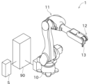
- FIG. 1 is a perspective view showing the configuration of a robot according to a first embodiment of the present disclosure
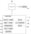
- FIG. FIG. 2 is a block diagram schematically showing the electrical configuration of the robot and state monitoring device
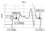
- Graph showing an example of current time-series data Graph showing the relationship between encoder temperature and grease temperature.
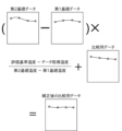
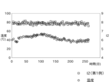
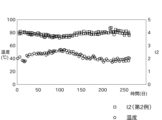
- FIG. 4 is a conceptual diagram for explaining correction performed on comparison data; Graph showing changes in I2 and temperature over time. Graph showing changes in I2 and temperature over time. 4 is a graph showing the transition of I2 after correction over time.
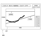
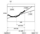
- FIG. 10 is a diagram showing an example of a screen displayed on the display unit for predicting the failure date based on the transition of I2 after correction; A graph for explaining a change in the prediction line for obtaining the failure prediction date linked to the number of reference days.
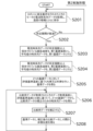
- FIG. 4 is a flowchart showing processing performed in the state monitoring device
- FIG. 2 is a block diagram schematically showing the electrical configuration of a condition monitoring device in a second embodiment
- FIG. 9 is a flowchart showing processing performed in the state monitoring device of the second embodiment
- FIG. 12 is a conceptual diagram illustrating processing performed on comparison data before correction in the fifth embodiment
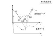
- FIG. 12 is a conceptual diagram illustrating processing performed on comparison data before correction in the sixth embodiment
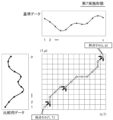
- FIG. 11 is a conceptual diagram for explaining the DTW method used in the seventh embodiment
- the graph which shows the temperature dependence of current time-series data regarding 8th Embodiment. 18 is a graph showing changes in motor speed corresponding to FIG. 17;
- FIG. 1 is a perspective view showing the configuration of the robot 1 according to the first embodiment of the present disclosure.
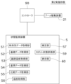
- FIG. 2 is a block diagram showing electrical configurations of the robot 1 and the state monitoring device 5. As shown in FIG.
- a state monitoring device 5 according to the present disclosure is applied to a robot (industrial robot) 1 as shown in FIG. 1, for example.
- the robot 1 performs operations such as painting, cleaning, welding, and transportation on the work to be worked.
- the robot 1 is implemented by, for example, a vertically articulated robot.
- the robot 1 includes a swivel base 10, an articulated arm 11, and a wrist portion 12.
- the swivel base 10 is fixed to the ground (for example, the floor of a factory).
- the articulated arm 11 has multiple joints.
- the wrist part 12 is attached to the tip of the articulated arm 11 .
- An end effector 13 is attached to the wrist portion 12 to work on a work to be worked.
- the robot 1 has an arm driving device 21.
- These drive devices are composed of, for example, an actuator configured as a servomotor, a reducer, and the like. However, the configuration of the driving device is not limited to the above.
- Each actuator is electrically connected to the controller 90 .
- the actuator operates to reflect command values input from the controller 90 .
- each servomotor that configures the arm drive device 21 is transmitted to each joint of the multi-joint arm 11, the swivel base 10, and the wrist portion 12 via a reduction gear.
- Each servomotor is attached with an unillustrated encoder for detecting its rotational position.
- the robot 1 works by reproducing the motions recorded by teaching.
- the controller 90 controls the actuators so that the robot 1 reproduces a series of actions taught in advance by the teacher.
- Teaching to the robot 1 can be performed by a teacher operating a teaching pendant (not shown).
- a program for moving the robot 1 is generated by teaching the robot 1.
- a program is generated each time the robot 1 is taught. If the operation to be taught to the robot 1 is different, the program is also different. By switching the program to be executed among a plurality of programs, the action to be performed by the robot 1 can be changed.
- the controller 90 is configured as a known computer including, for example, a CPU, ROM, RAM, auxiliary storage device, and the like.
- the auxiliary storage device is configured as, for example, an HDD, SSD, or the like.
- a program for moving the robot 1 and the like are stored in the auxiliary storage device.
- the state monitoring device 5 is connected to the controller 90 as shown in FIG.
- the state monitoring device 5 acquires, via the controller 90, changes such as the current value of the current flowing through the actuator (servomotor).
- this current value corresponds to a state signal reflecting the state of the robot 1 .
- the transition of the current value can be expressed by repeatedly acquiring the current value at short time intervals and arranging many current values in time series.
- the data obtained by arranging the values of the state signals in time series may be referred to as time series data.
- the state monitoring device 5 can determine whether there is an abnormality in the robot 1 by monitoring the acquired time-series data.
- the condition monitoring device 5 mainly targets the servo motors and speed reducers of the respective joints and determines whether or not there is an abnormality.
- abnormality includes a situation in which some kind of situation that is a sign of malfunction/impossibility does not occur in the servomotor, speed reducer, or bearing.
- the state monitoring device 5 includes a time-series data acquisition unit 51, a basic data acquisition unit (current-related basic data acquisition unit) 52, a basic temperature acquisition unit 53, and a comparison data acquisition unit (current-related A data acquisition unit 55 , a temperature acquisition unit 56 , a correction unit 57 , a robot state evaluation unit 59 , and a display unit 60 .
- the state monitoring device 5 is configured as a known computer including a CPU, ROM, RAM, auxiliary storage device, and the like.
- the auxiliary storage device is configured as, for example, an HDD, SSD, or the like.
- Programs for evaluating the state of the robot 1 and the like are stored in the auxiliary storage device.
- the computer can operate as a time-series data acquisition unit 51, a basic data acquisition unit 52, a basic temperature acquisition unit 53, a comparison data acquisition unit 55, a temperature acquisition unit 56, a correction unit 57, and a robot state. It can be operated as the evaluation unit 59, the display unit 60, and the like.
- the time-series data acquisition unit 51 acquires the time-series data described above.
- the time-series data acquisition unit 51 acquires time-series data for all servo motors included in the arm driving device 21 of the robot 1 .
- the time-series data is individually acquired for each of the plurality of servomotors (in other words, the plurality of speed reducers) arranged in each part of the robot 1 .
- the state signal is the current value.
- the current value means a measured value obtained by measuring the magnitude of the current flowing through the servomotor with a sensor.
- the sensor is provided in a servo driver (not shown) that controls the servo motor.
- a sensor may be provided for monitoring separately from the servo driver.
- a current command value given to the servomotor by the servo driver may be employed as the status signal.
- the servo driver feedback-controls the servo motor so that the current current value approaches the current command value. Therefore, for the purpose of detecting an abnormality in the servomotor or speed reducer, there is almost no difference between the current value and the current command value.
- the magnitude of the torque of the servo motor is proportional to the magnitude of the current. Therefore, a torque value or a torque command value may be used as the state signal.
- a deviation (rotational position deviation) between the target value for the rotational position of the servomotor and the actual rotational position obtained by the encoder may be used as the status signal.
- the servo driver gives a current command value obtained by multiplying this deviation by a gain to the servo motor. Therefore, the transition of the rotational position deviation shows a tendency similar to the transition of the current command value.
- the time-series data acquisition unit 51 acquires time-series data for each servo motor each time the robot 1 reproduces the instructed motion. However, instead of acquiring the time-series data for all reproduction operations, for example, it is possible to acquire only one or several reproduction operations per day.
- the time-series data acquisition unit 51 acquires time-series data of the current value flowing through each servomotor between the timing at which the acquisition start signal is received and the timing at which the acquisition end signal is received.
- the acquisition start signal and acquisition end signal are output by the controller 90, for example.
- the graph in FIG. 3 shows an example of current values flowing through the servo motors of certain joints when the robot 1 performs a regenerative motion. As shown in FIG. 3, the current value of the servomotor is zero before the reproduction operation program is executed. At this time, since an electromagnetic brake (not shown) operates at each joint, the attitude of the multi-joint arm 11 and the like is maintained.
- the program for the reproduction operation of the robot 1 is started.
- the brake is released, and almost at the same time, current begins to flow through the servomotor.
- the output shaft of the servomotor is controlled to stop.
- the rotation of the servomotor is started. Thereby, the motion of the robot 1 is substantially started.
- the controller 90 After the brake is released, the controller 90 outputs an acquisition start signal to the state monitoring device 5 (and thus the time-series data acquisition section 51) at a point shortly before the rotation of the servomotor starts.
- the controller 90 outputs an acquisition end signal to the time-series data acquisition section 51 after the servomotor stops rotating and before the program ends.
- the time-series data is a number of current values obtained by repeated detection at short, constant time intervals and arranged in chronological order. Therefore, current values in time-series data are sampled values.
- a time interval (sampling interval) for detecting the current value is, for example, several milliseconds.
- the sampling interval of the current value may match the control cycle of the robot 1 or may differ.
- the time-series data corresponds to the transition of the current value from the timing of the acquisition start signal to the timing of the acquisition end signal in the graph of FIG.
- the acquisition start signal or the acquisition end signal may be practically realized using other existing signals without preparing specially for measurement such as acquisition of time-series data.
- the falling edge of the "regeneration in progress" signal which is mainly used for safety purposes, can be used as the acquisition end signal.
- the time-series data acquisition unit 51 repeatedly acquires time-series data over a long period of time while the robot 1 is operating in a factory or the like.
- the basic data acquisition unit 52 obtains two pieces of basic data based on the time series data acquired by the time series data acquisition unit 51.
- the two basic data correspond to two different temperatures.
- the two basic data and the corresponding two different temperatures are the information on which the temperature compensation is based.
- Two basic data and two corresponding different temperatures are acquired for a period of time when the robot 1 is considered new and normal. This fixed period can also be called a learning period.
- the time when the robot 1 is regarded as new and normal typically means immediately after installation of the robot 1, but it may be after a trial run or break-in run for a while.
- the basic temperature acquisition unit 53 acquires temperatures corresponding to two pieces of basic data.
- the time-series data acquiring unit 51 obtains time-series data for a plurality of times by causing the robot 1 to perform the playback motion a plurality of times including the first time.
- the number of playback operations is arbitrary.
- the temperature at the time of acquisition of the time-series data is also acquired.
- the temperature can be detected, for example, by a temperature sensor (not shown) provided in the encoder described above.
- the no-load running torque which is the loss torque of the speed reducer
- this temperature can be considered the temperature of the grease, which is the lubricant inside the speed reducer.
- the speed reducer is usually located on the output shaft side of the motor, and the case of the motor and the case of the speed reducer are often in contact with each other.
- the temperature of the grease is affected by the temperature of the motor as well as the ambient air temperature.
- the encoder is located on the side opposite to the output shaft of the motor (the side opposite to the output shaft), and the case of the encoder is often in contact with the motor case.
- the temperature of the encoder is also affected by the temperature of the motor as well as the ambient air temperature.
- FIG. 4 is a graph showing the result of verification of the relationship between the encoder temperature and the grease temperature by the inventor of the present application.
- the vertical axis indicates the temperature of the grease
- the horizontal axis indicates the temperature of the encoder.
- a durability test was conducted by having the robot repeatedly perform a certain operation.
- the graph shows two test results (diamond plot and square plot) when the robot repeatedly performed different actions. From the linear correlation between the two, the temperature of the grease can be estimated from the detected value of the encoder temperature. It is also possible to evaluate the encoder temperature as the grease temperature.
- the temperature sensor may be provided at a location different from the encoder.
- a room temperature sensor that measures the room temperature of the factory where the robot 1 operates can be used as the temperature sensor.
- a single room temperature sensor measurement value can be shared by a plurality of servo motors.
- the temperature detected by the temperature sensor is handled in units of 1°C, for example, by rounding down decimal places. It is not limited to this, and may be handled in units of 0.5° C., for example.
- time-series data Due to various factors such as time, weather, season, etc., temperature fluctuations occur when acquiring time-series data. For example, 60 playback operations including the first time yielded 60 time-series data, 5 of which were obtained when the temperature was 25°C, and another 5 were obtained when the temperature was 45°C. Consider the case where is obtained when .
- the 60 reproduction operations including the first time means the aforementioned learning period for temperature compensation.
- the basic data acquisition unit 52 of this embodiment acquires the first basic data by averaging five pieces of time-series data corresponding to a temperature of 25°C. Further, the basic data acquisition unit 52 obtains the second basic data by averaging the five pieces of time-series data corresponding to the temperature of 45°C. Each of the first basic data and the second basic data is time-series data of average values.
- the temperature at the time of acquiring the first basic data may be referred to as the first basic temperature
- the temperature at the time of acquiring the second basic data may be referred to as the second basic temperature.
- the basal temperature acquisition unit 53 acquires the first basal temperature (25° C.) and the second basal temperature (45° C.).
- the first basic data corresponds to the first current-related basic data
- the second basic data corresponds to the second current-related basic data
- the basic data acquisition unit 52 can also use one piece of time-series data as the first basic data as it is, instead of using time-series data of average values.
- the time-series data of current values contain many noise components. Therefore, it is preferable to use the average of a plurality of time-series data as the first basic data from the viewpoint of improving reliability.
- the second basic data is also preferably an average of a plurality of time-series data. In the above example, the average of five pieces of time-series data is obtained, but the number is not limited to five, and the number of pieces of time-series data is arbitrary as long as it is plural. From the viewpoint of reliability, the more time-series data to be averaged, the better.
- the first basal temperature and the second basal temperature are set so that the temperature difference between the two is not too small, and that a sufficient number of time-series data are obtained for both the first basal temperature and the second basal temperature. , as appropriate.
- a known filtering process may be performed on the first basic data and the second basic data.
- the comparison data acquisition unit 55 acquires comparison data.
- the time-series data that is the source of the first basic data and the second basic data is acquired only in the early stage, but the time-series data acquired in the initial stage and later is used as comparison data.
- the replay motions repeated by the robot 1 can be divided into 60 replay motions including the first replay motion and subsequent replay motions.
- the basic data acquisition unit 52 acquires the first basic data and the second basic data from the initial 60 time-series data.
- the comparison data acquisition unit 55 acquires comparison data from the initial 60 reproduction operations and subsequent reproduction operations.
- the time series data can be used as it is as the comparison data, or the time series data can be filtered and used as the comparison data.
- the basic data and comparison data are prepared for each reproduction operation of the robot 1 (in other words, for each program).
- the basic data and comparison data may be acquired for all the motions that have been taught, but for example, the main motion of the robot 1, or a simple motion that is not the main one but played back once a day. If there is an action to be performed, basic data and comparison data may be obtained only for this action.
- the temperature acquisition unit 56 acquires the temperature at the time of data acquisition when the comparison data acquisition unit 55 acquires comparison data.
- the temperature can be obtained in the same way as the basal temperature described above.
- the temperature at which the comparison data is acquired may be referred to as the data acquisition temperature.
- the filtering process performed on the basic data and the comparison data is performed, for example, to remove noise, etc. contained in the time-series data. Since the filtering process for data is well known, detailed description is omitted, but any filter such as a moving average filter, a CR circuit simulation filter, or the like can be used.
- the correction unit 57 corrects the influence of temperature change on the comparison data.
- a predetermined evaluation reference temperature is defined as a reference for data comparison. If the temperature at which the comparison data was acquired differs from the evaluation reference temperature, the correction unit 57 corrects the comparison data so that it corresponds to the data at the evaluation reference temperature.
- the first basic data, the first basic temperature, the second basic data, and the second basic temperature are used for this correction.
- the first basal temperature is 25°C
- the second basal temperature is 45°C
- the data acquisition temperature is 32°C
- the evaluation reference temperature is 30°C.
- the temperature ratio R2 is a ratio that indicates how close the data acquisition temperature is to the evaluation reference temperature. If the absolute value of the difference between the data acquisition temperature and the evaluation reference temperature is small, the temperature ratio R2 will be a value close to 0, and if the absolute value of the difference between the data acquisition temperature and the evaluation reference temperature is large, the temperature ratio R2 will range from 0 to 0. The values are separated in the positive or negative direction. In addition, the temperature ratio R2 indicates the magnitude relationship between the data acquisition temperature and the evaluation reference temperature. If the evaluation reference temperature is higher than the data acquisition temperature, R2 is positive, and if the evaluation reference temperature is lower than the data acquisition temperature, R2 is negative.
- the temperature ratio R2 is used to correct the comparison data. Therefore, the temperature ratio R2 can also be called a temperature ratio for correction.
- the correction unit 57 multiplies the difference obtained by subtracting the first basic data from the second basic data by the temperature ratio R2, and converts the obtained result into data for comparison. add to As described above, corrected comparison data is obtained.
- the post-correction comparison data means time-series data estimated assuming that it was acquired at the evaluation reference temperature instead of the data acquisition temperature. As described above, this correction is performed linearly in consideration of the difference between the temperature (data acquisition temperature) at the time of acquisition of the comparison data and the evaluation reference temperature.
- the robot state evaluation unit 59 evaluates the state of the robot 1 (each unit) based on the comparison data corrected by the correction unit 57 .
- the robot state evaluation unit 59 calculates statistics based on the corrected comparison data (time-series data).
- I2 is the root mean square value of the current.
- PTP is an abbreviation for Peak to Peak, and is a value obtained by subtracting a low peak current value from a high peak current value of a current waveform.
- PEAK is the larger of the absolute value of the maximum current and the absolute value of the minimum current. For example, if the current waveform has a maximum current value of +15A and a minimum current value of -12A, PEAK will be 15A. If the current waveform has a maximum current value of +11A and a minimum current value of -14A, PEAK will be 14A.
- FIG. 6 shows the transition of the value of I2 and the temperature transition in the first example for one of the servo motors provided in the robot 1 .
- FIG. 7 shows changes in the value of I2 and changes in temperature in the second example.
- the horizontal axis is time (specifically, elapsed days). The two data were acquired at the same time, and the temperature transitions are identical in the two graphs.
- the robot state evaluation unit 59 outputs the obtained statistics such as I2.
- the robot state evaluation unit 59 can plot statistics such as I2 over time and calculate a trend line indicating the trend. Since the trend line is well known, it will be briefly described.
- the trend line can be obtained as a straight line that approximates the point group plotted on the graph.
- the approximate straight line can be obtained by using the known method of least squares, but the method is not limited.
- the robot state evaluation unit 59 calculates the date and time when the trend line obtained as described above reaches a predetermined lifespan threshold.
- the robot state evaluation unit 59 can predict the remaining life of the servomotor or the like by calculating the period from the present to the date and time.
- the display unit 60 is configured as, for example, a liquid crystal display.
- the display unit 60 can display, for example, a variety of information such as a transition over time of a statistic such as I2 and a trend line.
- the current value I2 monitor does not tend to increase due to deterioration, but in the example of the graph in FIG. 9, the current value I2 monitor increases due to deterioration.
- the scale in the direction of the vertical axis is set large in order to explain the changes in an easy-to-understand manner.
- FIG. 9 shows an example of output to the display unit 60 by the state monitoring device 5.
- the state monitoring device 5 predicts the future change of the evaluation value based on the past tendency of the evaluation value obtained based on the current value time-series data, and displays it on the display unit 60.
- the predicted failure date of the robot 1 is obtained based on the changing mode of .
- the condition monitoring device 5 can display a trend management screen as shown in FIG. Therefore, the condition monitoring device 5 also functions as a maintenance support device.
- the trend management screen includes a graph display section 61.
- the state monitoring device 5 can change the display mode of the graph displayed on the graph display unit 61 as shown in FIG.
- one end of the horizontal axis of the graph display portion 61 is the drawing start date
- the other end of the horizontal axis is the drawing end date.
- the period from the drawing start date to the drawing end date corresponds to the display period of the evaluation value, the prediction line, and the like.
- the drawing start date and drawing end date can be changed. For example, if the drawing start date is the first number of days before the current date and the drawing end date is the second number of days after the current date, the operator sets these first and second days independently. Can be changed. This allows the operator to grasp the evaluation value within the desired range.
- the post-correction comparison data is time-series data that is estimated when it is assumed to have been acquired at the evaluation reference temperature. Therefore, the influence of temperature change can be eliminated. As a result, the robot state evaluation unit 59 can more appropriately evaluate the state of the robot 1 .
- the evaluation reference temperature is determined to be a temperature different from the first basal temperature and the second basal temperature.
- the evaluation reference temperature may be equal to either the first basal temperature or the second basal temperature.
- the time-series data acquisition unit 51 of the state monitoring device 5 acquires current time-series data each time the robot 1 performs one reproduction operation, and stores the current time-series data together with information on the date and time of acquisition and temperature. (step S101).
- the state monitoring device 5 repeats the above process until a predetermined period of time elapses (step S102).
- the basal temperature acquisition unit 53 of the state monitoring device 5 acquires the lowest temperature at which, for example, five or more pieces of current time-series data are stored as the first basal temperature. Further, the basic data acquisition unit 52 obtains time series data of average values based on the plurality of current time series data acquired at the first basic temperature (step S103). The time-series data of this average value is the first basic data.
- the basal temperature acquisition unit 53 acquires, as the second basal temperature, the maximum temperature at which, for example, five or more pieces of current time-series data are stored.
- the basic data acquiring unit 52 obtains average time-series data based on the plurality of current time-series data acquired at the second basic temperature (step S104). The time-series data of this average value is the second basic data.
- Steps S101 to S104 are the preparatory process, that is, the learning period for temperature compensation. Next, the process of actually evaluating the state of the robot 1 is started.
- the comparison data acquisition unit 55 acquires time series data from the time series data acquisition unit 51 .
- This time-series data is comparison data.
- the temperature obtaining unit 56 obtains the temperature when the comparison data is obtained. This temperature is the data acquisition temperature.
- the correction unit 57 calculates the above temperature ratio R2 based on the difference between the evaluation reference temperature and the data acquisition temperature.
- the correction unit 57 multiplies the difference obtained by subtracting the first basic data from the second basic data by the temperature ratio R2.
- time-series data for correcting the comparison data can be obtained (step S105).
- the correction unit 57 corrects the comparison data by adding the time-series data to the comparison data (step S106).
- the robot state evaluation unit 59 calculates statistics such as I2 for the comparison data corrected in step S106, and outputs them to the display unit 60 (step S107).
- the state monitoring device 5 of this embodiment monitors the state of the robot 1 that can reproduce predetermined actions.
- the condition monitoring device 5 includes a basic data acquisition unit 52 , a basic temperature acquisition unit 53 , a comparison data acquisition unit 55 , a temperature acquisition unit 56 , a correction unit 57 and a robot condition evaluation unit 59 .
- the basic data acquisition unit 52 acquires first basic data, which is current data, and second basic data, which is current data, regarding the current of the motor that drives the robot 1 .
- the basal temperature acquisition unit 53 acquires a first basal temperature, which is the temperature when the first basic data is obtained, and a second basal temperature, which is the temperature when the second basic data is obtained.
- the comparison data acquisition unit 55 acquires comparison data, which is current data, regarding the current of the motor.
- the temperature acquisition unit 56 acquires the data acquisition temperature, which is the temperature at the time of acquisition of the comparison data.
- the correction unit 57 corrects the comparison data based on the first basic data, the second basic data, the first basic temperature, the second basic temperature, and the data acquisition temperature.
- the robot state evaluation unit 59 evaluates the state of the robot 1 using the corrected comparison data.
- the robot state evaluation unit 59 calculates I2, the maximum current value, the minimum current value, PTP, or PEAK based on the corrected comparison data, and the calculation result The state of the robot is evaluated based on
- the first basic data, the second basic data, and the comparison data are current time-series data.
- the correction unit 57 corrects the comparison data so that it corresponds to the data at the predetermined evaluation reference temperature.
- the correction unit 57 linearly corrects the current-related data.
- each of the first basic data and the second basic data is average value time-series data based on a plurality of time-series data.
- the condition monitoring device 5 includes a reference data acquisition unit 54 in addition to the configuration of the first embodiment.
- the reference data acquisition unit 54 obtains reference data based on the two pieces of basic data obtained by the basic data acquisition unit 52.
- Reference data means time-series data corresponding to the above-mentioned evaluation reference temperature. Specifically, the reference data is obtained by estimating the time-series data at the evaluation reference temperature by interpolation or extrapolation based on the first basic data and the second basic data.
- the evaluation reference temperature is 30°C.
- the first basal temperature is 25°C
- the second basal temperature is 45°C
- the temperature ratio R1 is a ratio that indicates how close the evaluation reference temperature is to the first basal temperature. If the evaluation reference temperature is close to the first basic temperature, the temperature ratio R1 will be close to 0, and if the evaluation reference temperature is close to the second basic temperature, the temperature ratio R1 will be close to 1.
- the reference data acquisition unit 54 multiplies the difference obtained by subtracting the first basic data from the second basic data by the temperature ratio R1, and adds the obtained result to the first basic data. As described above, the reference data is obtained.
- the first basic data and the second basic data are plotted in this multidimensional space.
- the reference data corresponds to a point obtained by internally dividing a line segment connecting a point of the first basic data and a point of the second basic data in the multidimensional space.
- the internal division ratio at this time is determined based on a ratio indicating how close the evaluation reference temperature is to the first and second basal temperatures.
- reference data is obtained by externally dividing the line segment connecting the points of the two basic data, instead of internally dividing it.
- reference data can also be obtained by extrapolation.
- the reference data obtained as described above means time-series data estimated when it is assumed that it is obtained at the evaluation reference temperature, not at the first basal temperature or the second basal temperature.
- the basic data and reference data are prepared for each reproduction operation of the robot 1 (in other words, for each program). Although basic data and reference data may be acquired for all taught actions, for example, a main action to be performed by the robot 1, or a simple non-main action that is reproduced once a day. Basic data and reference data may be acquired only for the movement of the body, if any.
- the robot state evaluation unit 59 calculates the Euclidean distance (dissimilarity) indicating the magnitude of the difference between the corrected comparison data and the reference data.
- the robot state evaluation unit 59 outputs the obtained Euclidean distance as an evaluation amount.
- the Euclidean distance D between the time-series data a and the time-series data b is represented by the following formula (1), where m is the length (number of elements) of the time-series data.
- the robot state evaluation unit 59 uses the Euclidean distance calculated as described above to evaluate the state of the robot 1 (each unit). Specifically, the robot state evaluation unit 59 uses each Euclidean distance obtained for each servo motor to evaluate the state of the servo motor.
- the Euclidean distance can be considered as a numerical representation of the degree of this divergence.
- the robot state evaluation unit 59 uses the Euclidean distance to determine whether or not there is an abnormality in each of the servomotors of the six joints. Further, based on the transition of the Euclidean distance with the passage of time up to the present, it is possible to predict the timing at which the servo motor will malfunction/be disabled in the future.
- the robot state evaluation unit 59 can calculate a trend line that indicates the tendency of the Euclidean distance over time.
- the robot state evaluation unit 59 calculates the date and time when the trend line obtained as described above reaches a predetermined life threshold.
- the robot state evaluation unit 59 can predict the remaining life of the servomotor or the like by calculating the period from the present to the date and time.
- the display unit 60 is configured as, for example, a liquid crystal display.
- the display unit 60 can display, for example, various information such as the transition of the Euclidean distance over time and trend lines.
- the reference data is time-series data that is estimated when it is assumed to have been acquired at the evaluation reference temperature. The same applies to the corrected comparison data. Therefore, the effect of temperature change can be removed when calculating the dissimilarity. As a result, the robot state evaluation unit 59 can more appropriately evaluate the state of the robot 1 .
- the evaluation reference temperature is determined to be a temperature different from the first basal temperature and the second basal temperature.
- the evaluation reference temperature may be equal to either the first basal temperature or the second basal temperature.
- the value of the above-mentioned temperature ratio R1 becomes 0 or 1, so the calculation becomes simple.
- Steps S201 to S204 in FIG. 13 are the same as steps S101 to S104 in FIG. 11, respectively, so description thereof will be omitted.
- step S205 the process of step S205 is performed after step S204 and before step S206.
- the reference data acquisition unit 54 interpolates or extrapolates the first basic data and the second basic data based on the aforementioned evaluation reference temperature to obtain time-series data. This time-series data is reference data.
- Steps S206 and S207 in FIG. 13 are the same as steps S105 and S106 in FIG. 11, respectively, so description thereof will be omitted.
- step S208 the robot state evaluation unit 59 obtains the degree of dissimilarity between the reference data obtained in step S205 and the comparison data corrected in step S207.
- the obtained dissimilarity is output to the display unit 60 .
- reference data to be compared with the comparison data is obtained based on the first basic data and the second basic data.
- the robot state evaluation unit 59 obtains the degree of dissimilarity between the comparison data and the reference data.
- the robot state evaluation unit 59 obtains the Euclidean distance between the comparison data and the reference data as the degree of dissimilarity.
- the correction unit 57 adds (evaluation reference temperature ⁇ data acquisition temperature)/(second basic temperature ⁇ second 1 basal temperature) is added to the comparison data to perform linear correction.
- the corrected comparison data is used to calculate statistics such as I2, and the state of the robot 1 is evaluated based on these statistics.
- reference data is created, and the similarity between the reference data and the corrected comparison data is focused on. is being evaluated.
- any of the above evaluation methods can be applied, with some exceptions.
- dissimilarity such as the Euclidean distance between the reference data and the comparison data, in addition to the evaluation with statistics. It means that you can also evaluate
- the current ratio obtained from the temperature ratio is used. Interpolate or extrapolate.
- the reference data can be obtained.
- the correction unit 57 multiplies the difference obtained by subtracting the first basic data from the second basic data by f (evaluation reference temperature - data acquisition temperature) / f (second basic temperature - first basic temperature). is added to the current-related data to perform linear correction.
- the correction unit 57 corrects the comparison data by a method different from that of the above embodiments.
- the first basic data and the second basic data which are current time-series data, are obtained at different temperatures. If there is a difference in current value between the first basic data and the second basic data, this difference in current value is the combination of the dry friction torque variation and the no-load running torque variation. Equivalent to.
- Dry friction torque refers to loss torque when the number of revolutions of the motor is near zero, and means loss torque due to known dry friction. However, the torque when the number of revolutions of the motor is near zero is considered to include loss torque other than dry friction torque, such as hysteresis loss.
- the no-load running torque means loss torque due to the viscosity of the lubricant when the motor is rotated without load.
- the current value corresponding to the sum of the dry friction torque and the no-load running torque may be referred to as the loss torque current value.
- the loss torque current value has the property of increasing by 1/A each time the temperature increases by a predetermined unit temperature tU .
- A is a number larger than one. Any combination of values of A and t U can be determined. For example, when t U is 10° C., the value of A can be set to 1.1 or more and 1.6 or less, depending on the type of speed reducer. For example, the value of A may be changed between the high temperature range and the low temperature range.
- the loss torque current value I lt,tp1 at the first basic temperature is obtained by using the current value of the first basic data as I 1 , the current value of the second basic data as I 2 , and the first basic temperature as tp 1 .
- I lt,tp1 (I 1 -I 2 )/(1-A ⁇ ((tp 1 -tp 2 )/t U ))
- the loss torque current value Ilt,tpX at the data acquisition temperature tpX can be expressed by the following equation.
- I lt,tpX I lt,tp1 ⁇ A ⁇ ((tp 1 -tp X )/t U )
- the loss torque current value Ilt,tpS at the evaluation reference temperature tpS can be expressed by the following equation.
- I lt,tpS I lt,tp1 ⁇ A ⁇ ((tp 1 -tp S )/t U )
- the comparison data I COMP corrected to correspond to the evaluation reference temperature tp S can be obtained.
- I COMP I ORIG -I lt,tpX +I lt,tnS
- the first basic data, the second basic data, and the current-related data are current time-series data.
- the correction unit 57 corrects the comparison data with respect to the temperature characteristic of the loss torque of the motor.
- the correction unit 57 increases the current value corresponding to the loss torque by 1/A each time the temperature increases by a predetermined unit temperature tU , where A is a number greater than 1. Compensation is performed on the comparison data using the following relationship.
- A is 1.1 or more and 1.6 or less when the unit temperature t U is 10°C.
- the correction unit 57 can also correct the comparison data so as to cancel the current corresponding to the loss torque of the motor.
- the current corresponding to the loss torque of the motor can be removed from the current time series data. Therefore, the evaluation becomes simpler, which may be advantageous for evaluating the state of the robot 1 .
- the robot state evaluation unit 59 moves relatively in the time axis direction in order to match the phase of the comparison data with the reference data (comparison target data). The difference is that the processing to cause
- the robot state evaluation unit 59 of the present embodiment performs a process of moving the waveform of the comparison data in multiple steps in the time axis direction.
- the robot state evaluation unit 59 acquires the Euclidean distance (dissimilarity) between the comparison data and the reference data for each stage by calculation.
- FIG. 14 shows an example in which the comparison data is moved by two steps, one step in the negative direction of the time axis and one step in the positive direction.
- the Euclidean distance is calculated for three stages including no movement. Both the amount of movement in the direction of the time axis per stage and the number of stages of movement can be determined arbitrarily.
- this waveform shift uniformly shifts the correspondence between the m current values included in the reference data and the m current values included in the comparison data. can be practically realized.
- the robot state evaluation unit 59 obtains the minimum Euclidean distance.
- the minimum value of this Euclidean distance is used as an evaluation value.
- the robot state evaluation unit 59 moves at least one of the waveform of the reference data and the waveform of the comparison data in the time axis direction in a plurality of stages. while obtaining the dissimilarity between the two waveforms. With the comparison data moved so that the dissimilarity between the two waveforms is minimized, the robot state evaluation unit 59 obtains the dissimilarity between the reference data and the comparison data.
- the correction unit 57 corrects the i-th current value among the m current values included in the reference data and the i ⁇ p-th to i+p-th current values among the m current values included in the comparison data. Calculate the difference between the current value of and , respectively.
- the correction unit 57 checks which of the i ⁇ pth to i+pth current values of the comparison data is closest to the ith current value of the reference data.
- the i ⁇ 1th has the smallest absolute value of difference with respect to the ith current value of the reference data.
- the difference is -0.2.
- the correction unit 57 corrects the i-th current value of the comparison data so that it becomes the (i-1)-th current value with the minimum absolute value of the difference.
- the correction unit 57 repeats the above processing for all m current values of the reference data.
- the comparison data can be moved in the direction of the time axis to some extent and expanded or contracted in the direction of the time axis to some extent so as to increase the degree of similarity to the reference data.
- the robot state evaluation unit 59 obtains the Euclidean distance between the reference data and the corrected comparison data as the degree of dissimilarity. This enables appropriate evaluation.
- reference data to be compared with the comparison data is obtained based on at least one of the first basic data and the second basic data.
- the robot state evaluation unit 59 selects the closest sampled value to the i-th sampled value of the waveform of the reference data among the i ⁇ p-th to i+p-th sampled values (where i and p are integers equal to or greater than 1) of the comparison data. Modify the i-th sampled value of the comparison data with the sampled value.
- the robot state evaluation unit 59 obtains the degree of dissimilarity between the corrected comparison data and the reference data.
- the condition monitoring device 5 of this embodiment includes a reference data acquisition unit 54, as in the second embodiment described above.
- the robot state evaluation unit 59 uses the DTW distance is obtained and used as an evaluation value.
- DTW is an abbreviation for Dynamic Time Warping.
- the DTW method is used to calculate the degree of similarity between two time series data.
- a major feature of the DTW method is that it allows non-linear expansion and contraction of time-series data in the direction of the time axis when calculating the degree of similarity. As a result, the DTW method can obtain a result close to human intuition regarding the degree of similarity of time-series data.
- the robot state evaluation unit 59 calculates the DTW distance (dissimilarity) indicating the magnitude of the difference between the comparison data and the reference data, and outputs this value as an evaluation value.
- a plurality (s) of current values included in the reference data are arranged in chronological order along a first axis extending in the horizontal direction.
- a plurality (p) of current values included in the comparison data are arranged in chronological order along the second axis extending in the vertical direction.
- Each cell (c, d) represents correspondence between the c-th current value in the reference data and the d-th current value in the comparison data. However, 1 ⁇ c ⁇ d.
- Each cell (c, d) is associated with a numerical value representing the difference between the c-th current value in the reference data and the d-th current value in the comparison data.
- the absolute value of the difference between the c-th current value and the d-th current value is stored in association with each cell.
- the robot state evaluation unit 59 obtains a warping path from the starting point cell located in the lower left corner of the matrix in FIG. 16 to the ending point cell located in the upper right corner.
- the starting point cell (1, 1) is the current value at the earliest timing (that is, the first) in the time series among the s current values in the reference data, and the p current values in the comparison data, This corresponds to associating the earliest timing (that is, the first) current value in the time series.
- the end point cell (s, p) is the current value at the last timing (that is, the sth) in the time series among the s current values in the reference data, and the current value in the p current values in the comparison data. This corresponds to associating the last timing (that is, the p-th) current value in the sequence.
- a route starting from the starting point cell and reaching the ending point cell is considered according to the following rules [1] and [2]. [1] You can only move to adjacent cells vertically, horizontally, or diagonally. [2] The reference data cannot be moved back in time, and the comparison data cannot be moved back in time either.
- a series of such cells is called a route or warping path.
- a warping path indicates how s current values in the reference data are associated with p current values in the comparison data. From another point of view, the warping path represents how the two pieces of time-series data are expanded or contracted along the time axis.
- the robot state evaluation unit 59 calculates the sum of numerical values (in this embodiment, the absolute value of the difference between the c-th current value and the d-th current value) that represent the differences associated with the passing cells in the possible warping paths. Find the warping path that minimizes . In the following, this warping pass may be called an optimal warping pass. Also, the total value of the values in each square in this optimal warping path is sometimes called the DTW distance. The robot state evaluation unit 59 obtains this DTW distance.
- the DTW distance average value By dividing the DTW distance by the number of squares passed through, the DTW distance average value can be obtained.
- the DTW distance average value may be obtained by dividing the DTW distance by the number of elements s or p of any time-series data. Instead of the DTW distance, the DTW distance average value can also be used as the evaluation value.
- the robot state evaluation unit 59 of this embodiment obtains an optimum warping path using a DP matching technique (dynamic programming).
- DP is an abbreviation for Dynamic Programming. Since the DP matching method is well known, the explanation is omitted.
- reference data to be compared with the comparison data is obtained based on at least one of the first basic data and the second basic data.
- the robot state evaluation unit 59 obtains the DTW distance between the comparison data and the reference data as the degree of dissimilarity.
- the first basic data, the second basic data, and the comparison data are all time-series data of current values, and statistics are calculated from the comparison data.
- the first basic data, the second basic data, and the comparison data are data obtained by statistically appropriately processing the time-series data of current values.
- I2 maximum current value
- minimum current value PTP, and PEAK
- the first basic data, second basic data, and comparison data are simple scalar quantities. Therefore, calculations for interpolation or extrapolation are simplified when calculating the reference data and when correcting the comparison data.
- the first current-related basic data, the second current-related basic data, and the current-related data are I2, the maximum current value, the minimum current value, PTP , or PEAK.
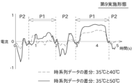
- the graph in FIG. 17 shows the current waveform obtained by subtracting the current waveform at 40° C. from the current waveform at 35° C., and the current waveform obtained by subtracting the current waveform at 50° C. from the current waveform at 35° C. for one of the servo motors provided in the robot 1. something is shown.
- the vertical axis of the graph is current value, and the horizontal axis is time (specifically, seconds). Since the two differential waveforms are clearly different, it can be seen that the current waveform has temperature dependence.
- the graph in FIG. 18 shows changes in the speed of the servomotor when the robot 1 is caused to perform a regenerative operation with the current waveform corresponding to FIG.
- the vertical axis of the graph is speed
- the horizontal axis is time (specifically, seconds).
- the time on the horizontal axis of FIG. 18 corresponds to the time on the horizontal axis of FIG.
- the period during which the robot 1 performs the regenerative operation with the current waveform that is the basis of the differential waveform in FIG. is included.
- the first period P1 indicated by the white arrow is the period during which the rotation of the motor is substantially zero.
- the current value in this first period P1 is considered to correspond to the dry friction torque.
- a second period P2 without an arrow is a period during which the rotation of the motor does not become substantially zero.
- the current value in this second period P2 is considered to correspond to the no-load running torque.
- the correction unit 57 can correct the comparison data only for one of the first period P1 and the second period P2 shown in FIG. Further, for example, for the first period P1, the simple linear correction as shown in the first embodiment is performed on the comparison data, while for the second period P2, the temperature increases by a predetermined unit temperature tU .
- the comparison data can be corrected by using the property of 1/A times each time. Alternatively, simple linear correction may be performed for both periods, and correction may be made from the basic data divided into the respective periods. Furthermore, using the property that the temperature increases by 1/A each time the temperature increases by a predetermined unit temperature t U in both periods, the comparison data can be corrected with a different value of A for each period.
- the time-series data of the current value is divided into a period in which the rotation of the motor is substantially zero and a period in which it is not, and the correction method or parameters performed by the correction unit 57 are different for each period.
- corrections are made to only one of the two. This makes it possible to more effectively remove the influence of temperature change.
- the correction unit 57 sets the comparison data to the first period P1 in which the motor rotation speed is substantially zero and the period P1 in which the motor rotation speed is substantially zero. and a second period P2 which is essentially non-zero, only one of the first period P1 and the second period P2 is corrected. Alternatively, different corrections are performed between the first period P1 and the second period P2.
- the state monitoring device 5 does not have to be directly connected to the robot 1, and may acquire time-series data reflecting the state of the robot 1 from the controller 90 of the robot 1, for example, via a communication line such as the Internet.
- the controller 90 acquires and stores the current value in real time during the reproduction operation, and by batch processing or the like, outputs the program number, the date and time of acquisition of the current value, the information identifying the servomotor, and the time-series data of the current value. It is transmitted collectively to the state monitoring device 5 .
- the state monitoring device 5 may be incorporated in the controller 90 instead of being provided separately from the controller 90 .
- the state monitoring device 5 may be realized by using the computer of the controller 90 of the robot 1 without providing the computer functioning as the CPU, ROM, RAM, auxiliary storage device, etc. of the state monitoring device 5 .
- each element including the condition monitoring device 5 disclosed above are general-purpose processors, dedicated processors, integrated circuits, ASICs (Application Specific Integrated Circuits) configured or programmed to perform the disclosed functions, It can be implemented using circuitry or processing circuitry including conventional circuitry and/or combinations thereof.
- a processor is considered a processing circuit or circuit because it includes transistors and other circuits.
- a circuit, unit, or means is hardware that performs or is programmed to perform the recited functions.
- the hardware may be the hardware disclosed herein, or other known hardware programmed or configured to perform the recited functions.
- a circuit, means or unit is a combination of hardware and software, where the hardware is a processor which is considered a type of circuit, the software being used to configure the hardware and/or the processor.
- a state monitoring device for monitoring the state of an industrial robot capable of reproducing a predetermined motion First current-related basic data, which is at least one current data or statistical data of the current data, and first current-related basic data, which is at least one current data or statistical data of the current data, regarding the current of the motor that drives the industrial robot.
- a current-related basic data acquisition unit for acquiring current-related basic data
- a basal temperature acquisition unit that acquires a first basal temperature, which is the temperature at the time of acquiring the first current-related basic data, and a second basal temperature, which is the temperature at the time of acquiring the second current-related basic data
- a current-related data acquiring unit for acquiring at least one piece of current data or current-related data, which is statistical data of the current data, regarding the current of the motor
- a temperature acquisition unit that acquires a data acquisition temperature that is the temperature at the time of acquisition of the current-related data
- a correction unit that corrects the current-related data based on the first current-related basic data, the second current-related basic data, the first basic temperature, the second basic temperature, and the data acquisition temperature
- a robot state evaluation unit that evaluates the state of the robot using the corrected current-related data
- a condition monitoring device comprising:
- (Item 2) The condition monitoring device according to item 1,
- the robot state evaluation unit based on the corrected current-related data, the root mean square of the current, maximum current, the minimum value of the current, A value obtained by subtracting the current value of the low peak from the current value of the high peak of the current waveform, or the absolute value of the maximum current or the absolute value of the minimum current, whichever is greater; is calculated, and the state of the robot is evaluated based on the calculation result.
- Comparison target data to be compared with the current-related data is obtained based on at least one of the first current-related basic data and the second current-related basic data, The state monitoring device, wherein the robot state evaluation unit obtains a degree of dissimilarity between the current-related data and the comparison target data.
- the condition monitoring device (Item 4) The condition monitoring device according to item 1, The robot state evaluation unit obtains a Euclidean distance between the current-related data and the comparison target data as the degree of dissimilarity.
- the condition monitoring device (Item 5) The condition monitoring device according to item 3 or 4, The robot state evaluation unit obtains a degree of dissimilarity between the current-related data and the comparison target data while moving the current-related data relative to the comparison target data in a plurality of steps in a time axis direction. , In a state in which the current-related data is relatively moved so that the dissimilarity becomes a minimum value, the robot state evaluation unit obtains the dissimilarity between the current-related data and the comparison target data. surveillance equipment.
- the condition monitoring device (Item 6) The condition monitoring device according to item 3, The robot state evaluation unit obtains a DTW distance between the current-related data and the comparison target data as the degree of dissimilarity.
- the condition monitoring device (Item 8) The condition monitoring device according to item 1,
- the first current-related basic data, the second current-related basic data, and the current-related data are the root mean square of the current, maximum current, the minimum value of the current, A value obtained by subtracting the current value of the low peak from the current value of the high peak of the current waveform, or A condition monitoring device that is the larger of the absolute value of the maximum current and the absolute value of the minimum current.
- the condition monitoring device according to any one of items 1 to 7 or item 9,
- the correction unit adds (said evaluation reference temperature - said data acquisition temperature) / ( said second basic temperature - said first 1 basal temperature) is added to the current-related data to perform linear correction.
- f the evaluation reference temperature - the data acquisition temperature
- f the second basal temperature - the first basal temperature
- the condition monitoring device according to any one of items 1 to 7 or any one of items 9 to 11,
- the first current-related basic data, the second current-related basic data, and the current-related data are current time-series data
- the correction unit corrects the current-related data so that it corresponds to data at a predetermined evaluation reference temperature, corrects the temperature characteristics of the loss torque of the motor, or cancels the current corresponding to the loss torque of the motor.
- the condition monitoring device according to any one of items 1 to 7 or any one of items 9 to 12,
- the correction unit calculates the current-related A condition monitoring device that corrects data.
- the condition monitoring device according to any one of items 1 to 7 or any one of items 9 to 12,
- the correction unit divides the time-series data of the current-related data into a first period in which the number of rotations of the motor is substantially zero and a second period in which the number of rotations of the motor is not substantially zero. different corrections for the first period and the second period, respectively.
- a state monitoring method for monitoring the state of an industrial robot capable of reproducing a predetermined motion First current-related basic data, which is at least one current data or statistical data of the current data, and first current-related basic data, which is at least one current data or statistical data of the current data, regarding the current of the motor that drives the industrial robot.
- Acquire current-related basic data Acquiring a first basic temperature, which is the temperature at the time of acquiring the first current-related basic data, and a second basic temperature, which is the temperature at the time of acquiring the second current-related basic data, obtaining at least one current data or current-related data, which is statistical data of the current data, for the current of the motor; Acquiring a data acquisition temperature, which is the temperature at the time of acquisition of the current-related data; correcting the current-related data based on the first current-related basic data, the second current-related basic data, the first basic temperature, the second basic temperature, and the data acquisition temperature; A state monitoring method, wherein the corrected current-related data is used for robot state evaluation.
Landscapes
- Engineering & Computer Science (AREA)
- Physics & Mathematics (AREA)
- General Physics & Mathematics (AREA)
- Automation & Control Theory (AREA)
- Robotics (AREA)
- Mechanical Engineering (AREA)
- Manipulator (AREA)
- Numerical Control (AREA)
Abstract
Description

Ilt,tp1=(I1-I2)/(1-A^((tp1-tp2)/tU))
Ilt,tpX=Ilt,tp1×A^((tp1-tpX)/tU)
評価基準温度tpSにおけるロストルク電流値Ilt,tpSは、以下の式で表すことができる。
Ilt,tpS=Ilt,tp1×A^((tp1-tpS)/tU)
ICOMP=IORIG-Ilt,tpX+Ilt,tnS
以上により、補正部57による補正が完了する。
前記産業用ロボットを駆動するモータの電流について、少なくとも1つの電流データ又は前記電流データの統計データである第1電流関連基礎データ、及び、少なくとも1つの電流データ又は前記電流データの統計データである第2電流関連基礎データを取得する電流関連基礎データ取得部と、
前記第1電流関連基礎データの取得時における温度である第1基礎温度、及び、前記第2電流関連基礎データの取得時における温度である第2基礎温度を取得する基礎温度取得部と、
前記モータの電流について、少なくとも1つの電流データ又は前記電流データの統計データである電流関連データを取得する電流関連データ取得部と、
前記電流関連データの取得時における温度であるデータ取得温度を取得する温度取得部と、
前記第1電流関連基礎データ、前記第2電流関連基礎データ、前記第1基礎温度、前記第2基礎温度、及び前記データ取得温度に基づいて、前記電流関連データに対して補正を行う補正部と、
補正後の前記電流関連データを用いてロボットの状態評価を行うロボット状態評価部と、
を備える、状態監視装置。
前記ロボット状態評価部は、補正後の前記電流関連データに基づいて、
電流の2乗平均平方根、
電流の最大値、
電流の最小値、
電流波形の高いピークの電流値から低いピークの電流値を減算した値、又は、
電流の最大値の絶対値及び最小値の絶対値のうち大きい方の値、
を計算し、この計算結果に基づいてロボットの状態評価を行う、状態監視装置。
前記第1電流関連基礎データ及び前記第2電流関連基礎データのうち少なくとも何れかに基づいて、前記電流関連データと比較される比較対象データが求められ、
前記ロボット状態評価部は、前記電流関連データと前記比較対象データとの非類似度を求める、状態監視装置。
前記ロボット状態評価部は、前記電流関連データと前記比較対象データとの間のユークリッド距離を、前記非類似度として求める、状態監視装置。
前記ロボット状態評価部は、前記電流関連データを、前記比較対象データに対して時間軸方向に複数段階で相対移動させながら、前記電流関連データと前記比較対象データとの間の非類似度を求め、
前記非類似度が最小値となるように前記電流関連データを相対移動させた状態において、前記ロボット状態評価部は、前記電流関連データと前記比較対象データとの間の非類似度を求める、状態監視装置。
前記ロボット状態評価部は、前記電流関連データと前記比較対象データとの間のDTW距離を、前記非類似度として求める、状態監視装置。
前記第1電流関連基礎データ、前記第2電流関連基礎データ、及び前記電流関連データが、電流の時系列データである、状態監視装置。
前記第1電流関連基礎データ、前記第2電流関連基礎データ、及び前記電流関連データが、
電流の2乗平均平方根、
電流の最大値、
電流の最小値、
電流波形の高いピークの電流値から低いピークの電流値を減算した値、又は、
電流の最大値の絶対値及び最小値の絶対値のうち大きい方の値である、状態監視装置。
前記補正部は、所定の評価基準温度におけるデータに相当するように、前記電流関連データに対して補正を行う、状態監視装置。
前記補正部は、前記第2電流関連基礎データから前記第1電流関連基礎データを減算して得られる差分に、(前記評価基準温度-前記データ取得温度)/(前記第2基礎温度-前記第1基礎温度)を乗じたものを前記電流関連データに加算することで、線形の補正を行う、状態監視装置。
前記補正部は、電流変化ΔIを温度変化Δtpにより表す関数をΔI=f(Δtp)としたときに、前記第2電流関連基礎データから前記第1電流関連基礎データを減算して得られる差分に、f(前記評価基準温度-前記データ取得温度)/f(前記第2基礎温度-前記第1基礎温度)を乗じたものを前記電流関連データに加算することで、線形の補正を行う、状態監視装置。
前記第1電流関連基礎データ、前記第2電流関連基礎データ、及び前記電流関連データが、電流の時系列データであり、
前記補正部は、前記電流関連データに対して、所定の評価基準温度におけるデータに相当するように補正し、前記モータのロストルクの温度特性に関して補正し、又は、モータのロストルクに相当する電流をキャンセルするように補正する、状態監視装置。
前記補正部は、Aを1より大きい数としたときに、温度が所定の単位温度増加する毎に前記モータのロストルクに相当する電流値が1/A倍となる関係を用いて、前記電流関連データに対して補正を行う、状態監視装置。
前記補正部は、前記電流関連データの時系列データを、前記モータの回転数が実質的にゼロである第1期間と、前記モータの回転数が実質的にゼロでない第2期間と、に区分したときに、前記第1期間と前記第2期間のそれぞれに対して互いに異なる補正を行う、状態監視装置。
前記産業用ロボットを駆動するモータの電流について、少なくとも1つの電流データ又は前記電流データの統計データである第1電流関連基礎データ、及び、少なくとも1つの電流データ又は前記電流データの統計データである第2電流関連基礎データを取得し、
前記第1電流関連基礎データの取得時における温度である第1基礎温度、及び、前記第2電流関連基礎データの取得時における温度である第2基礎温度を取得し、
前記モータの電流について、少なくとも1つの電流データ又は前記電流データの統計データである電流関連データを取得し、
前記電流関連データの取得時における温度であるデータ取得温度を取得し、
前記第1電流関連基礎データ、前記第2電流関連基礎データ、前記第1基礎温度、前記第2基礎温度、及び前記データ取得温度に基づいて、前記電流関連データに対して補正を行い、
補正後の前記電流関連データをロボットの状態評価のために使用する、状態監視方法。
Claims (15)
- 予め決められた動作を再生可能な産業用ロボットの状態を監視する状態監視装置であって、
前記産業用ロボットを駆動するモータの電流について、少なくとも1つの電流データ又は前記電流データの統計データである第1電流関連基礎データ、及び、少なくとも1つの電流データ又は前記電流データの統計データである第2電流関連基礎データを取得する電流関連基礎データ取得部と、
前記第1電流関連基礎データの取得時における温度である第1基礎温度、及び、前記第2電流関連基礎データの取得時における温度である第2基礎温度を取得する基礎温度取得部と、
前記モータの電流について、少なくとも1つの電流データ又は前記電流データの統計データである電流関連データを取得する電流関連データ取得部と、
前記電流関連データの取得時における温度であるデータ取得温度を取得する温度取得部と、
前記第1電流関連基礎データ、前記第2電流関連基礎データ、前記第1基礎温度、前記第2基礎温度、及び前記データ取得温度に基づいて、前記電流関連データに対して補正を行う補正部と、
補正後の前記電流関連データを用いてロボットの状態評価を行うロボット状態評価部と、
を備える、状態監視装置。 - 請求項1に記載の状態監視装置であって、
前記ロボット状態評価部は、補正後の前記電流関連データに基づいて、
電流の2乗平均平方根、
電流の最大値、
電流の最小値、
電流波形の高いピークの電流値から低いピークの電流値を減算した値、又は、
電流の最大値の絶対値及び最小値の絶対値のうち大きい方の値、
を計算し、この計算結果に基づいてロボットの状態評価を行う、状態監視装置。 - 請求項1に記載の状態監視装置であって、
前記第1電流関連基礎データ及び前記第2電流関連基礎データのうち少なくとも何れかに基づいて、前記電流関連データと比較される比較対象データが求められ、
前記ロボット状態評価部は、前記電流関連データと前記比較対象データとの非類似度を求める、状態監視装置。 - 請求項3に記載の状態監視装置であって、
前記ロボット状態評価部は、前記電流関連データと前記比較対象データとの間のユークリッド距離を、前記非類似度として求める、状態監視装置。 - 請求項3に記載の状態監視装置であって、
前記ロボット状態評価部は、前記電流関連データを、前記比較対象データに対して時間軸方向に複数段階で相対移動させながら、前記電流関連データと前記比較対象データとの間の非類似度を求め、
前記非類似度が最小値となるように前記電流関連データを相対移動させた状態において、前記ロボット状態評価部は、前記電流関連データと前記比較対象データとの間の非類似度を求める、状態監視装置。 - 請求項3に記載の状態監視装置であって、
前記ロボット状態評価部は、前記電流関連データと前記比較対象データとの間のDTW距離を、前記非類似度として求める、状態監視装置。 - 請求項1に記載の状態監視装置であって、
前記第1電流関連基礎データ、前記第2電流関連基礎データ、及び前記電流関連データが、電流の時系列データである、状態監視装置。 - 請求項1に記載の状態監視装置であって、
前記第1電流関連基礎データ、前記第2電流関連基礎データ、及び前記電流関連データが、
電流の2乗平均平方根、
電流の最大値、
電流の最小値、
電流波形の高いピークの電流値から低いピークの電流値を減算した値、又は、
電流の最大値の絶対値及び最小値の絶対値のうち大きい方の値である、状態監視装置。 - 請求項1に記載の状態監視装置であって、
前記補正部は、所定の評価基準温度におけるデータに相当するように、前記電流関連データに対して補正を行う、状態監視装置。 - 請求項1に記載の状態監視装置であって、
前記補正部は、前記第2電流関連基礎データから前記第1電流関連基礎データを減算して得られる差分に、(前記評価基準温度-前記データ取得温度)/(前記第2基礎温度-前記第1基礎温度)を乗じたものを前記電流関連データに加算することで、線形の補正を行う、状態監視装置。 - 請求項1に記載の状態監視装置であって、
前記補正部は、電流変化ΔIを温度変化Δtpにより表す関数をΔI=f(Δtp)としたときに、前記第2電流関連基礎データから前記第1電流関連基礎データを減算して得られる差分に、f(前記評価基準温度-前記データ取得温度)/f(前記第2基礎温度-前記第1基礎温度)を乗じたものを前記電流関連データに加算することで、線形の補正を行う、状態監視装置。 - 請求項1に記載の状態監視装置であって、
前記第1電流関連基礎データ、前記第2電流関連基礎データ、及び前記電流関連データが、電流の時系列データであり、
前記補正部は、前記電流関連データに対して、所定の評価基準温度におけるデータに相当するように補正し、前記モータのロストルクの温度特性に関して補正し、又は、モータのロストルクに相当する電流をキャンセルするように補正する、状態監視装置。 - 請求項1に記載の状態監視装置であって、
前記補正部は、Aを1より大きい数としたときに、温度が所定の単位温度増加する毎に前記モータのロストルクに相当する電流値が1/A倍となる関係を用いて、前記電流関連データに対して補正を行う、状態監視装置。 - 請求項1に記載の状態監視装置であって、
前記補正部は、前記電流関連データの時系列データを、前記モータの回転数が実質的にゼロである第1期間と、前記モータの回転数が実質的にゼロでない第2期間と、に区分したときに、前記第1期間と前記第2期間のそれぞれに対して互いに異なる補正を行う、状態監視装置。 - 予め決められた動作を再生可能な産業用ロボットの状態を監視する状態監視方法であって、
前記産業用ロボットを駆動するモータの電流について、少なくとも1つの電流データ又は前記電流データの統計データである第1電流関連基礎データ、及び、少なくとも1つの電流データ又は前記電流データの統計データである第2電流関連基礎データを取得し、
前記第1電流関連基礎データの取得時における温度である第1基礎温度、及び、前記第2電流関連基礎データの取得時における温度である第2基礎温度を取得し、
前記モータの電流について、少なくとも1つの電流データ又は前記電流データの統計データである電流関連データを取得し、
前記電流関連データの取得時における温度であるデータ取得温度を取得し、
前記第1電流関連基礎データ、前記第2電流関連基礎データ、前記第1基礎温度、前記第2基礎温度、及び前記データ取得温度に基づいて、前記電流関連データに対して補正を行い、
補正後の前記電流関連データをロボットの状態評価のために使用する、状態監視方法。
Priority Applications (3)
| Application Number | Priority Date | Filing Date | Title |
|---|---|---|---|
| JP2023558076A JP7850175B2 (ja) | 2021-11-04 | 2022-11-04 | 状態監視装置及び状態監視方法 |
| EP22890023.9A EP4427892A4 (en) | 2021-11-04 | 2022-11-04 | STATE MONITORING DEVICE AND STATE MONITORING METHOD |
| CN202280072710.8A CN118201746A (zh) | 2021-11-04 | 2022-11-04 | 状态监视装置以及状态监视方法 |
Applications Claiming Priority (2)
| Application Number | Priority Date | Filing Date | Title |
|---|---|---|---|
| JP2021180648 | 2021-11-04 | ||
| JP2021-180648 | 2021-11-04 |
Publications (1)
| Publication Number | Publication Date |
|---|---|
| WO2023080203A1 true WO2023080203A1 (ja) | 2023-05-11 |
Family
ID=86241559
Family Applications (1)
| Application Number | Title | Priority Date | Filing Date |
|---|---|---|---|
| PCT/JP2022/041201 Ceased WO2023080203A1 (ja) | 2021-11-04 | 2022-11-04 | 状態監視装置及び状態監視方法 |
Country Status (4)
| Country | Link |
|---|---|
| EP (1) | EP4427892A4 (ja) |
| JP (1) | JP7850175B2 (ja) |
| CN (1) | CN118201746A (ja) |
| WO (1) | WO2023080203A1 (ja) |
Cited By (2)
| Publication number | Priority date | Publication date | Assignee | Title |
|---|---|---|---|---|
| WO2024247716A1 (ja) * | 2023-05-31 | 2024-12-05 | パナソニックIpマネジメント株式会社 | 情報処理方法、情報処理装置、及びプログラム |
| CN120228732A (zh) * | 2025-05-29 | 2025-07-01 | 山西兰一科技有限公司 | 一种基于互联网的工业机器人故障检测系统 |
Citations (3)
| Publication number | Priority date | Publication date | Assignee | Title |
|---|---|---|---|---|
| JP2006281421A (ja) * | 2005-04-05 | 2006-10-19 | Yaskawa Electric Corp | ロボットおよびロボットの異常検出方法 |
| JP2007190663A (ja) | 2006-01-23 | 2007-08-02 | Seiko Epson Corp | メンテナンス方法及びロボットコントローラ |
| JP2019141983A (ja) * | 2018-02-23 | 2019-08-29 | 川崎重工業株式会社 | ロボット制御装置 |
Family Cites Families (4)
| Publication number | Priority date | Publication date | Assignee | Title |
|---|---|---|---|---|
| US11347191B2 (en) * | 2015-07-29 | 2022-05-31 | Illinois Tool Works Inc. | System and method to facilitate welding software as a service |
| CN113382690B (zh) * | 2019-03-08 | 2023-11-14 | 柯惠Lp公司 | 用于差动传感器的偏置和偏移的模拟温度补偿的方法 |
| CN113547544B (zh) * | 2020-04-26 | 2023-01-24 | 北京配天技术有限公司 | 一种摩擦辨识方法、摩擦辨识装置以及机器人 |
| CN112589832B (zh) * | 2020-12-04 | 2022-04-29 | 成都卡诺普机器人技术股份有限公司 | 一种确定机器人关节最大工作力矩的方法 |
-
2022
- 2022-11-04 WO PCT/JP2022/041201 patent/WO2023080203A1/ja not_active Ceased
- 2022-11-04 CN CN202280072710.8A patent/CN118201746A/zh active Pending
- 2022-11-04 EP EP22890023.9A patent/EP4427892A4/en active Pending
- 2022-11-04 JP JP2023558076A patent/JP7850175B2/ja active Active
Patent Citations (3)
| Publication number | Priority date | Publication date | Assignee | Title |
|---|---|---|---|---|
| JP2006281421A (ja) * | 2005-04-05 | 2006-10-19 | Yaskawa Electric Corp | ロボットおよびロボットの異常検出方法 |
| JP2007190663A (ja) | 2006-01-23 | 2007-08-02 | Seiko Epson Corp | メンテナンス方法及びロボットコントローラ |
| JP2019141983A (ja) * | 2018-02-23 | 2019-08-29 | 川崎重工業株式会社 | ロボット制御装置 |
Non-Patent Citations (1)
| Title |
|---|
| See also references of EP4427892A4 |
Cited By (2)
| Publication number | Priority date | Publication date | Assignee | Title |
|---|---|---|---|---|
| WO2024247716A1 (ja) * | 2023-05-31 | 2024-12-05 | パナソニックIpマネジメント株式会社 | 情報処理方法、情報処理装置、及びプログラム |
| CN120228732A (zh) * | 2025-05-29 | 2025-07-01 | 山西兰一科技有限公司 | 一种基于互联网的工业机器人故障检测系统 |
Also Published As
| Publication number | Publication date |
|---|---|
| EP4427892A1 (en) | 2024-09-11 |
| JPWO2023080203A1 (ja) | 2023-05-11 |
| EP4427892A4 (en) | 2025-10-22 |
| JP7850175B2 (ja) | 2026-04-22 |
| CN118201746A (zh) | 2024-06-14 |
Similar Documents
| Publication | Publication Date | Title |
|---|---|---|
| TWI790696B (zh) | 狀態監視裝置、狀態異常判別方法以及狀態異常判別程式 | |
| CN104379308B (zh) | 机器人控制装置以及机器人控制方法 | |
| JP7850175B2 (ja) | 状態監視装置及び状態監視方法 | |
| JP7500839B2 (ja) | ロボット保守支援装置、ロボット保守支援方法、及びロボット保守支援プログラム | |
| JP7118249B2 (ja) | モータ制御装置 | |
| US7600435B2 (en) | Method of determining deterioration of pressurizing performance of spot welding gun | |
| JP3946753B2 (ja) | ロボットプログラム評価・修正方法及びロボットプログラム評価・修正装置 | |
| WO2019106875A1 (ja) | 異常判定システム、モータ制御装置、及び異常判定装置 | |
| US20190129381A1 (en) | Life prediction apparatus | |
| JP2017019080A (ja) | ロボット装置の測定方法、および回転駆動装置の測定方法 | |
| JP7043801B2 (ja) | 異常予兆報知システム、異常予兆報知方法及びプログラム | |
| JP7358049B2 (ja) | 制御方法、プログラム、記録媒体、ロボットシステム、および物品の製造方法 | |
| JP6721012B2 (ja) | モータ制御システム | |
| CN116635802B (zh) | 数控装置 | |
| CN116160478A (zh) | 一种工业机械臂关节故障检测方法和系统 | |
| CN111086023A (zh) | 基于工业机器人内部温度的定位精度补偿方法及其使用方法 | |
| JP7516013B2 (ja) | 処理装置、生産システム、ロボット装置、物品の製造方法、処理方法、プログラム及び記録媒体 | |
| JP6792131B2 (ja) | モータ制御システム | |
| JP2021088042A (ja) | ロボット制御装置、把持システムおよびロボットハンドの制御方法 | |
| CN116117792B (zh) | 一种机械臂的早期安全预警方法 | |
| CN110774318B (zh) | 处理装置及处理部分的处理方法 | |
| JP6796287B2 (ja) | モータ制御システム | |
| JP7637825B1 (ja) | 状態監視装置、状態監視方法及び状態監視プログラム | |
| US20260044142A1 (en) | Gmm for anomaly detection of harmonic drive | |
| Choi et al. | Deep Learning-Based Friction Compensation in Low Velocity for Enhanced Direct Teaching in Collaborative Manipulators |
Legal Events
| Date | Code | Title | Description |
|---|---|---|---|
| 121 | Ep: the epo has been informed by wipo that ep was designated in this application |
Ref document number: 22890023 Country of ref document: EP Kind code of ref document: A1 |
|
| ENP | Entry into the national phase |
Ref document number: 2023558076 Country of ref document: JP Kind code of ref document: A |
|
| WWE | Wipo information: entry into national phase |
Ref document number: 202280072710.8 Country of ref document: CN |
|
| WWE | Wipo information: entry into national phase |
Ref document number: 2022890023 Country of ref document: EP |
|
| NENP | Non-entry into the national phase |
Ref country code: DE |
|
| ENP | Entry into the national phase |
Ref document number: 2022890023 Country of ref document: EP Effective date: 20240604 |