WO2023083339A9 - Récepteur de force d'entraînement, ensemble rotatif et cartouche de traitement - Google Patents
Récepteur de force d'entraînement, ensemble rotatif et cartouche de traitement Download PDFInfo
- Publication number
- WO2023083339A9 WO2023083339A9 PCT/CN2022/131575 CN2022131575W WO2023083339A9 WO 2023083339 A9 WO2023083339 A9 WO 2023083339A9 CN 2022131575 W CN2022131575 W CN 2022131575W WO 2023083339 A9 WO2023083339 A9 WO 2023083339A9
- Authority
- WO
- WIPO (PCT)
- Prior art keywords
- driving force
- force receiving
- driving
- receiving member
- braking
- Prior art date
- Legal status (The legal status is an assumption and is not a legal conclusion. Google has not performed a legal analysis and makes no representation as to the accuracy of the status listed.)
- Ceased
Links
Images




Classifications
-
- G—PHYSICS
- G03—PHOTOGRAPHY; CINEMATOGRAPHY; ANALOGOUS TECHNIQUES USING WAVES OTHER THAN OPTICAL WAVES; ELECTROGRAPHY; HOLOGRAPHY
- G03G—ELECTROGRAPHY; ELECTROPHOTOGRAPHY; MAGNETOGRAPHY
- G03G21/00—Arrangements not provided for by groups G03G13/00 - G03G19/00, e.g. cleaning, elimination of residual charge
- G03G21/16—Mechanical means for facilitating the maintenance of the apparatus, e.g. modular arrangements
- G03G21/18—Mechanical means for facilitating the maintenance of the apparatus, e.g. modular arrangements using a processing cartridge, whereby the process cartridge comprises at least two image processing means in a single unit
- G03G21/1839—Means for handling the process cartridge in the apparatus body
- G03G21/1857—Means for handling the process cartridge in the apparatus body for transmitting mechanical drive power to the process cartridge, drive mechanisms, gears, couplings, braking mechanisms
- G03G21/1864—Means for handling the process cartridge in the apparatus body for transmitting mechanical drive power to the process cartridge, drive mechanisms, gears, couplings, braking mechanisms associated with a positioning function
-
- G—PHYSICS
- G03—PHOTOGRAPHY; CINEMATOGRAPHY; ANALOGOUS TECHNIQUES USING WAVES OTHER THAN OPTICAL WAVES; ELECTROGRAPHY; HOLOGRAPHY
- G03G—ELECTROGRAPHY; ELECTROPHOTOGRAPHY; MAGNETOGRAPHY
- G03G15/00—Apparatus for electrographic processes using a charge pattern
- G03G15/75—Details relating to xerographic drum, band or plate, e.g. replacing, testing
- G03G15/757—Drive mechanisms for photosensitive medium, e.g. gears
Definitions
- the present invention relates to the field of electrophotographic imaging, and in particular to a process cartridge detachably installed in an electrophotographic imaging apparatus and a rotating assembly and a driving force receiving member rotatably installed in the process box.
- Chinese patent application CN113574469A discloses a force output member (main assembly side driving force transmission unit) 203 provided in the imaging device M.
- the force output member 203 has a rotation axis M1 and includes an output drive The driving force output member (drum drive coupling) 180 of the force and the braking force output member (including the first brake combining member 204 and the second brake combining member 208) outputting the braking force, when the force output member 203 is as described below
- the braking force output member is driven by the driving force output member 180 and rotates together with the driving force output member.
- the two ends of the driving force output member 180 are respectively provided with a driving force output surface (drive transmission surface) 180d and a flange portion 180a; as shown in Figure 43, the first system
- the dynamic coupling member 204 has a flange portion 204a and a coupling coupling portion 204b protruding from the flange portion 204a.
- the coupling coupling portion 204b is configured to protrude toward the rotation axis M1 of the force output member like a claw
- the second The brake coupling member 208 also has a flange portion 208a and a coupling coupling portion 208b protruding from the flange portion 208a, which coupling coupling portion 208b is also configured to protrude like a claw toward the rotational axis M1 of the force output member , along the radial direction perpendicular to the rotation axis M1, the first brake coupling member 204 is located outside the second brake coupling member 208, the coupling coupling portion 204b is located outside the coupling coupling portion 208b, and the first brake coupling member 204 is located outside the coupling coupling portion 208b.
- the coupling member 204 and the second brake coupling member 208 are simultaneously rotatable about the rotation axis M1.
- FIG. 1A is a perspective view of a conventional process cartridge
- FIG. 1B is a perspective view of a rotating member equipped with a conventional driving force receiving member.
- the Chinese patent application CN113574469A also discloses a rotating member 21 equipped with an existing driving force receiving member X4 as shown in Figure 1B.
- the rotating member 21 and the driving force receiving member An existing process cartridge C including a first unit 100 and a second unit 200 coupled to each other and a driving force receiving member X4 for receiving driving force from an imaging device, the first unit 100 including a first unit housing 1 and a first rotating member 11 rotatably installed in the first unit housing 1, the second unit 200 includes a second unit housing 2 and a second rotating member rotatably installed in the second unit housing 2 21.
- the driving force receiving member X4 is provided at one longitudinal end of the process cartridge C and drives at least one of the first rotating member 11 and the second rotating member 21 to rotate.
- the driving force receiving member X4 is combined with the second rotating member 21, including the chassis X42, the base X43 and the coupling part Chassis X42, base
- the guide surface X463 extends spirally in the circumferential direction of the axis L21, and the driving surface X464 and the braking surface X465 are arranged adjacent to the guide surface.
- the guide surface X463 is located above the braking surface X465.
- the guide surface X463 abuts at least the coupling coupling portion 208b in the second braking coupling member 208 to guide the driving force receiving portion X46 into the driving force output surface 180d and the coupling. between the device coupling parts 208b/204b; when the process cartridge C is working, the driving force output surface 180d outputs driving force to the driving surface X464 to drive the rotating member 21 to rotate, and the braking force output member is used to rotate the driving force receiving portion The braking force is applied downstream to braking surface X465.
- the present invention provides a processing box to further develop the above technology, improve the combination efficiency of the driving force receiving member and the force output member, and prevent the driving force receiving member and the force output member from being combined and dislocated.
- the driving force receiving member provided by the invention is used to receive driving force from an imaging device.
- the imaging device is provided with a driving part and a braking part that rotate in the same direction.
- the braking part can rotate together with the driving part, and the braking part It is also movable relative to the driving part, and the braking part is located downstream of the driving part in the direction of rotation;
- the driving force receiving member is provided with a driving force receiving part for receiving the driving force;
- the driving force receiving part has a surface that can reach the downstream of the braking part , the braking part drives the driving force receiving member to rotate by contacting the surface.
- the driving part in the device to output the driving force, but only the braking part outputs the driving force, which is conducive to simplicity
- the structure of the driving force receiving part improves the coupling efficiency and stability between the driving force receiving part and the force output part, and prevents the coupling dislocation between the driving force receiving part and the force output part.
- the driving force receiving portion includes a bump having an opposite first surface and a second surface.
- the first surface is located upstream of the second surface along the rotation direction, and the first surface is used to communicate with the first surface.
- the braking part is in contact; the driving force receiving member is not braked by the braking part.
- the driving part and the braking part rotate around the rotation axis M1.
- the braking part includes a first braking combining member and a second braking combining member.
- the first braking combining member is located at the third
- the outer sides of the two brake combination members; at least a part of the driving part and at least a part of the first brake combination member are located on the same circumference; along the rotation direction of the force output member, the first brake combination member has an outer output surface located downstream , the second brake combination member has an inner output surface located downstream, the outer output surface and the inner output surface are both spirally arranged in the direction opposite to the rotation direction; the surface is a driving surface matching the outer output surface or the inner output surface .
- the driving part and the braking part rotate around the rotation axis M1.
- the braking part includes a first braking combining member and a second braking combining member.
- the first braking part The dynamic combination member is located outside the second brake combination member; at least a part of the driving part and at least a part of the first brake combination member are located on the same circumference; along the rotation direction of the force output member, the first brake combination member has a structure located downstream
- the outer output surface, the second brake combination member has an inner output surface located downstream and an inner protrusion protruding toward the rotation axis M1, the outer output surface and the inner output surface are both spirally arranged in the direction opposite to the rotation direction, and the inner protrusion
- the driving force receiving member receives the driving force by contacting the flat surface.
- the driving part when the braking part stops applying the driving force to the driving force receiving part, the driving part applies the braking force to the driving force receiving part.
- the driving force receiving member has a rotation axis L21 and includes a coupled portion and a coupling portion that are coupled to each other.
- the coupled portion is used to transmit the driving force received by the coupling portion;
- the coupling portion includes a bottom plate, a base plate, and a coupling portion.
- the center column and the driving force receiving part extend from one side of the base plate;
- the driving force receiving part includes a base and a bump located radially outside the center column, the bump is further away from the rotation axis L21 than the base, and the driving surface is provided on the bump; along the driving In the radial direction of the force receiving member, an escape portion is formed between the driving surface and the center column; when the driving force receiving member is combined with the force output member, the driving surface is combined with the outer output surface, and at least part of the second braking combination member enters Avoidance department.
- the driving force receiving member has a rotation axis L21 and includes a coupled portion and a coupling portion that are coupled to each other.
- the coupled portion is used to transmit the driving force received by the coupling portion;
- the coupling portion includes a bottom plate, a base plate, and a coupling portion.
- the center column and the driving force receiving part extend from one side of the base plate;
- the driving force receiving part includes a base and a bump located radially outside the center column, the bump is further away from the rotation axis L21 than the base, and the driving surface is provided on the bump;
- the coupling part is divided into a fixed coupling part and a movable coupling part movable relative to the fixed coupling part, and the driving force receiving part is provided on the movable coupling part.
- the movable joint part is a cantilever that is elastically deformable relative to the fixed joint part, or the movable joint part is configured to slide relative to the fixed joint part in a direction intersecting the rotation axis L21.
- the driving force receiving member has a rotation axis L21 and includes a connecting part, a chassis, a main body part and an auxiliary part.
- the main part is connected to the connecting part or the chassis, and the auxiliary part is rotatably arranged relative to the main body part.
- the driving force receiving part part is provided on the main part; when the driving force receiving part is combined with the force output part, the auxiliary part is used to separate the driving part and the braking part along the rotation direction.
- the auxiliary component includes a carrier body and at least one separation member protruding from the carrier body.
- the carrier body is rotatably combined with the main body part, and the separation member is used to enter between the driving part and the braking part so that the driving part and the braking part are Separate along the rotation direction;
- the auxiliary component also includes a restricted portion provided on the carrier or the separation component, and the main body portion is also provided with a function for combining with the restricted portion to restrict the auxiliary component along the rotation axis L21
- the limiting part; further, the auxiliary component also includes an elastic arm connected to the carrier, and the limited part is provided on the elastic arm.
- the carrier body is configured as a ring body with an accommodating cavity formed inside, at least a part of the main body is accommodated by the accommodating cavity, the limiting part is configured as an engaging protrusion protruding radially from the ring body toward the accommodating cavity, and the limiting part is provided It is an engaging groove combined with the engaging protrusion.
- the auxiliary member further includes at least one auxiliary protrusion protruding from the carrier body. During the combination of the driving force receiving member and the force output member, the auxiliary protrusion abuts the driving part and/or the braking part.
- the number of separators is 4-6.
- the driving force receiving part includes a bump provided with a driving surface, and along the rotation axis L21, the bump has a surface farthest from the connection part; along the rotation axis M1, the first brake binding member has a third at the end. Two surfaces, along the direction of rotation, the nearest distance between the second surface and the driving part is s, and the minimum size of the surface is greater than the distance s.
- the separation member is provided with a guide surface and an anti-separation part
- the guide surface is used to guide the separation member between the driving part and the braking part
- the anti-separation part is used to prevent the driving force receiving part from interacting with the force. Output pieces are separated.
- the anti-separation part is configured as a barb surface inclined relative to the rotation axis L21, and the barb surface faces the connecting part when viewed in a direction perpendicular to the rotation axis L21.
- the driving force receiving member includes an anti-separation portion for preventing the driving force receiving member from being separated from the force output member.
- the separation part and the protrusion are spaced apart from each other along the radial direction of the driving force receiving part.
- the present invention also provides a rotating assembly, which includes a rotating member and a driving force receiving member as described above, and the rotating member is driven by the driving force receiving member.
- the present invention also provides a process cartridge, which includes a housing and a rotating assembly as described above.
- the rotating member is rotatably supported by the housing, and the driving force receiving member directly or indirectly drives the rotating member.
- the auxiliary part is rotatably installed on the housing; when the auxiliary part is coaxially arranged with the main body part, along the radial direction of the driving force receiving part, the separating part and the bump spaced apart from each other.
- the rotating member is a photosensitive member rotatably installed in the housing.
- the process box also includes a charging member in contact with the photosensitive member and a friction member in contact with the charging member.
- the charging member is driven by the friction between the photosensitive member and the charging member. Rotate.
- the invention also relates to a process cartridge detachably installed in a device provided with a separation control mechanism.
- the process cartridge includes a first unit and a second unit that are combined with each other and are respectively installed in the first unit housing and the second unit.
- the developing roller and the photosensitive drum in the housing and the separation contact mechanism installed in the process box, the separation contact mechanism is used to receive the force exerted by the separation control mechanism; the separation control mechanism can be separated in the intermediate position and different from the intermediate position
- the force application position and the restoring force application position move back and forth, and the separation control mechanism always returns to the intermediate position after applying force to the separation contact mechanism;
- the separation contact mechanism includes a separation force receiving part and a restoring force relatively distributed in the front and rear direction.
- the receiving part and the locking part fixedly connected with the first unit housing; when the separation control mechanism reaches the separation force applying position from the intermediate position, the separation force receiving part receives the separation force that can cause the developing roller and the photosensitive drum to separate from each other, and the locking part is locked; when the separation control mechanism reaches the restoring force application position from the intermediate position, the restoring force receiving portion receives the restoring force that can bring the developing roller and the photosensitive drum closer to each other, and the locking portion is unlocked.
- the separation contact mechanism also includes a main body and an action part.
- the separation force receiving part and the restoring force receiving part are provided on the action part.
- the locking part is provided on the main body.
- the main body is fixedly connected to the first unit shell, and the action part is fixedly connected to the main body.
- the process cartridge further includes an end cap for combining the first unit and the second unit, and the separation contact mechanism further includes a locked portion for being combined with the locking portion, the locked portion being provided on the first unit or the second unit. on the unit or end cover.
- the locking part has a first protruding part, and the locked part includes a base plate and a second protruding part protruding from the base plate.
- the separation force receiving part receives the separation force
- the first protruding part and the second protruding part are combined with each other.
- the restoring force When the receiving part receives the restoring force, the first protruding part and the second protruding part are disengaged.
- the locking part and the locked part are locked; when the first protruding part crosses the second protruding part again and reaches the rear of the second protruding part, the locking part and the locked part The locked part is unlocked.
- One end of the substrate is fixed on one of the first unit, the second unit and the end cover, and the other end is suspended.
- the locking part and the locked part are located above the process box, and the action part is located below the process box.
- the separation contact mechanism also includes a locking component disposed in the action part.
- the process cartridge also includes a protective cover installed at one end of the first unit and a driving force receiving member for receiving driving force from the device and driving the developing roller to rotate.
- the protective cover is fixedly installed on the first unit housing, and the driving force receiving member is used to drive the developing roller to rotate.
- the force receiving part is located between the first unit shell and the protective cover, and the main body and the protective cover are fixedly connected.
- the main body and the protective cover are formed integrally or separately.
- Figure 1A is a perspective view of a conventional process cartridge.
- FIG. 1B is a perspective view of a rotating member equipped with a conventional driving force receiving member.
- Figure 2A is a perspective view of a conventional force output member.
- Figure 2B is a partial perspective view of a conventional force output member.
- FIG. 2C is a partial perspective view of the braking force output member in the existing force output member after it is hidden.
- FIG. 2D is a top view viewed along the rotation axis of the conventional force output member.
- 3A and 3B are perspective views of the process cartridge according to the present invention.
- FIG. 4A is a perspective view of the photosensitive drum of the driving force receiving member according to Embodiment 1 of the present invention.
- FIG. 4B is a perspective view of the first driving force receiving member according to Embodiment 1 of the present invention.
- FIG. 4C is a side view of the first driving force receiving member according to Embodiment 1 of the present invention when viewed along its rotation axis.
- FIG. 5A is a perspective view of the driving force receiving member according to Embodiment 2 of the present invention.
- 5B is a side view of the driving force receiving member according to Embodiment 2 of the present invention when viewed along its rotation axis.
- FIG. 6A is a perspective view of the driving force receiving member according to the third embodiment of the present invention.
- FIG. 6B is a side view of the driving force receiving member according to Embodiment 3 of the present invention when viewed along its rotation axis.
- Fig. 7 is a perspective view of the driving force receiving member according to the fourth embodiment of the present invention.
- FIGS. 8A and 8B are schematic diagrams of states before and after the driving force receiving member involved in Embodiment 4 of the present invention is combined with the driving force output member and the braking force output member in the device.
- FIG. 9 is a sectional view of the driving force receiving member according to Embodiment 4 of the present invention combined with the driving force output member and the braking force output member in the device, taken along a plane perpendicular to the rotation axis of the driving force receiving member.
- 10A and 10B are schematic diagrams of states before and after the driving force receiving member involved in Embodiment 5 of the present invention is combined with the driving force output member and the braking force output member in the device.
- FIG. 11A is a perspective view of a driving force receiving member according to Embodiment 6 of the present invention.
- 11B is a side view of the driving force receiving member viewed in a direction perpendicular to the rotation axis of the driving force receiving member according to Embodiment 6 of the present invention.
- 11C is a side view of the driving force receiving member according to Embodiment 6 of the present invention when viewed along the rotation axis of the driving force receiving member.
- FIG. 12A is a perspective view of a deformed structure of the driving force receiving member according to Embodiment 6 of the present invention.
- FIG. 12B is a side view of the driving force receiving member shown in FIG. 12A viewed along its rotation axis.
- FIG. 13A is a perspective view of another deformation structure of the driving force receiving member according to Embodiment 6 of the present invention.
- FIG. 13B is a side view of the driving force receiving member shown in FIG. 13A viewed in a direction perpendicular to the rotation axis of the driving force receiving member.
- FIG. 14A is a perspective view of the driving force receiving member according to Embodiment 7 of the present invention.
- 14B is a side view of the driving force receiving member viewed in a direction perpendicular to the rotation axis of the driving force receiving member according to Embodiment 7 of the present invention.
- FIG. 15A is a perspective view of a deformed structure of the driving force receiving member according to Embodiment 7 of the present invention.
- 15B is a side view of the driving force receiving portion viewed in a direction perpendicular to the rotation axis of the driving force receiving member according to Embodiment 7 of the present invention.
- FIG. 16A is a perspective view of a driving force receiving member according to Embodiment 8 of the present invention.
- FIG. 16B is a cross-sectional view taken along a plane perpendicular to the rotation axis in FIG. 16A and passing through the braking surface.
- Fig. 17 is a perspective view of the driving force receiving member according to Embodiment 9 of the present invention.
- Figure 18 is a perspective view of a deformed structure of the driving force receiving member according to Embodiment 9 of the present invention.
- Fig. 19 is a perspective view of a driving force receiving member according to Embodiment 10 of the present invention.
- FIG. 20A is a perspective view of the driving force receiving member beginning to be combined with the force output member according to Embodiment 10 of the present invention.
- FIG. 20B is a perspective view of the driving force receiving member and the force output member according to Embodiment 10 of the present invention after being combined.
- 20C is a side view of the driving force receiving member and the force output member according to Embodiment 10 of the present invention, viewed in a direction perpendicular to the rotation axis of the driving force receiving member.
- 21A is a perspective view of the driving force receiving member according to the eleventh embodiment of the present invention.
- FIG. 21B is an exploded schematic view of the driving force receiving member according to the eleventh embodiment of the present invention.
- Fig. 22 is a perspective view of the driving force receiving member according to Embodiment 12 of the present invention.
- FIG. 23A is a perspective view of the driving force receiving member beginning to be combined with the force output member according to Embodiment 12 of the present invention.
- FIG. 23B is a perspective view of the driving force receiving member and the force output member according to Embodiment 12 of the present invention after being combined.
- 23C is a side view of the driving force receiving member and the force output member according to Embodiment 12 of the present invention, viewed in a direction perpendicular to the rotation axis of the driving force receiving member.
- Figure 24 is an exploded schematic view of the driving force receiving member according to Embodiment 13 of the present invention.
- FIG. 25A is a perspective view of the driving force receiving member beginning to be combined with the force output member according to Embodiment 13 of the present invention.
- FIG. 25B is a perspective view of the driving force receiving member and the force output member according to Embodiment 13 of the present invention after being combined.
- 25C is a side view of the driving force receiving member and the force output member according to Embodiment 13 of the present invention, viewed in a direction perpendicular to the rotation axis of the driving force receiving member.
- Figure 26 is an exploded schematic view of the driving force receiving member according to Embodiment 14 of the present invention.
- 27A is a diagram of the state of the driving force receiving member in the process box before the driving force receiving member and the force output member are combined according to Embodiment 14 of the present invention.
- FIG. 27B is a perspective view of the driving force receiving member and the force output member before they are combined according to Embodiment 14 of the present invention.
- Figure 28 is a diagram showing the state of the driving force receiving member in the process box after the driving force receiving member and the force output member are combined according to Embodiment 14 of the present invention.
- Fig. 29 is a perspective view of the driving force receiving member according to Embodiment 15 of the present invention.
- FIG. 30A is a perspective view of the driving force receiving member according to Embodiment 15 of the present invention before being combined with the force output member in the first state, when viewed in a direction intersecting with the rotation axis of the driving force receiving member.
- FIG. 30B is a perspective view of the driving force receiving member according to Embodiment 15 of the present invention after being combined with the force output member in the first state, when viewed along another direction intersecting with the rotation axis of the driving force receiving member.
- 31A is a perspective view of the driving force receiving member according to Embodiment 15 of the present invention combined with the force output member in the first state.
- 31B is a perspective view of the driving force receiving member according to Embodiment 15 of the present invention after being combined with the force output member in the first state, when viewed in a direction perpendicular to the rotation axis of the driving force receiving member.
- FIG. 32 is a perspective view of the driving force receiving member according to Embodiment 15 of the present invention when it starts to be combined with the force output member in the second state, viewed in a direction perpendicular to the rotation axis of the driving force receiving member.
- Fig. 33 is a perspective view of the driving force receiving member according to Embodiment 16 of the present invention.
- 34A is a perspective view of the driving force receiving member and the driving force output member according to Embodiment 16 of the present invention after they are combined.
- 34B is a side view of the driving force receiving member and the driving force output member according to Embodiment 16 of the present invention when viewed in a direction perpendicular to the rotation axis of the driving force receiving member.
- Fig. 35 is a perspective view of the driving force receiving member according to Embodiment 17 of the present invention.
- FIG. 36 is a schematic diagram of the state after the coupling part of the driving force receiving member is separated from the base according to Embodiment 17 of the present invention.
- [Correction 23.12.2022 under Rule 91] 38 is a side view of the driving force receiving member and the force output member according to Embodiment 17 of the present invention when viewed in a direction perpendicular to the rotation axis of the driving force receiving member.
- Fig. 39 is a perspective view of the driving force receiving member according to Embodiment 18 of the present invention.
- Fig. 40 is a perspective view of the driving force receiving member according to Embodiment 19 of the present invention.
- Fig. 41 is a perspective view of the driving force receiving member and the force output member according to Embodiment 19 of the present invention after they are combined.
- FIG. 42A is a perspective view of the driving force receiving member according to Embodiment 20 of the present invention.
- Fig. 43 is a perspective view of the driving force receiving member and the force output member according to Embodiment 20 of the present invention.
- FIG. 44 is a cross-sectional view taken along the AA direction in FIG. 35 after the driving force receiving member and the force output member are combined according to Embodiment 20 of the present invention.
- Figure 45 is an exploded schematic view of the driving force receiving member according to Embodiment 21 of the present invention.
- FIG. 46A is a perspective view of the driving force receiving member according to Embodiment 21 of the present invention.
- 46B is a side view viewed along the rotation axis of the driving force receiving member according to Embodiment 21 of the present invention.
- 47A and 47B are state diagrams after the driving force receiving member and the force output member are combined according to Embodiment 21 of the present invention.
- Fig. 48 is a perspective view of the driving force receiving member according to Embodiment 22 of the present invention.
- Fig. 49 is a state diagram of the driving force receiving member and the force output member according to Embodiment 22 of the present invention after being combined.
- Fig. 50 is a perspective view of the driving force receiving member according to Embodiment 23 of the present invention.
- 51A-51D are schematic diagrams of the process of combining the driving force receiving member and the force output member according to Embodiment 23 of the present invention.
- Fig. 52 is a perspective view of the driving force receiving member according to the twenty-fourth embodiment of the present invention.
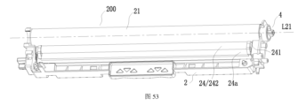
- Figure 53 is a perspective view of the second unit according to Embodiment 25 of the present invention after some components are hidden.
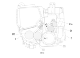
- FIG. 54 is a sectional view of the process cartridge having the second unit according to Embodiment 25 of the present invention, taken along a plane perpendicular to the rotation axis of the photosensitive drum.
- Figure 55 is an exploded schematic view of the first separation contact mechanism and the process cartridge housing in the process cartridge of the present invention.
- 56 is a side view of the process cartridge according to the present invention when viewed from left to right in the left-right direction and when the first separation contact mechanism is installed in the process cartridge housing.
- 57 is a side view of the process cartridge according to the present invention when viewed from left to right in the left-right direction and when the second separation contact mechanism is installed in the process cartridge housing.
- Figure 58 is an exploded schematic view of the third separation contact mechanism and the process cartridge housing in the process cartridge of the present invention.
- 59A to 59G are schematic diagrams of the motion process of the third separation contact mechanism in the process cartridge of the present invention controlling the separation and contact between the developing roller and the photosensitive drum under the action of the separation control mechanism.
- Figure 60 is an exploded schematic view of the fourth separation contact mechanism and the process cartridge housing in the process cartridge of the present invention.
- 61 is a side view of the process cartridge according to the present invention when the fourth separation contact mechanism is installed in the process cartridge housing when viewed from left to right in the left-right direction.
- Figure 62 is an exploded schematic view of the fifth separation contact mechanism and the process cartridge housing in the process cartridge of the present invention.
- 63a and 63b are side views of the process cartridge according to the present invention when the fifth separation contact mechanism is installed in the process cartridge housing when viewed from left to right in the left-right direction.
- 64A is a side view of the process cartridge having the sixth separation contact mechanism when viewed from left to right in the left and right direction before the separation receiving mechanism is pressed.
- 64B is a side view of the process cartridge having the sixth separation contact mechanism when viewed from left to right in the left and right direction after the process cartridge reaches the installation position and the separation receiving mechanism is pressed.
- 65A is a side view of the process cartridge having the seventh separation contact mechanism when viewed from left to right in the left and right direction before the separation receiving mechanism is pressed.
- 65B is a side view of the process cartridge having the seventh separation contact mechanism when viewed from left to right in the left and right direction after the process cartridge reaches the installation position and the separation receiving mechanism is pressed.
- first rotating member 11 and/or the second rotating member 21 described in the patent application of the background art can be driven directly by the driving force receiving member X4 or indirectly driven; the process cartridge C can either The first unit 100 and the second unit 200 are included simultaneously, or only any one of the first unit 100 and the second unit 200 is included.
- the developer is accommodated in the first unit housing 1 and is provided with the driving force receiving member X4.
- One side is called the driving end C1, and the opposite end is called the non-driving end C2.
- the driving end cover/first end cover 300 is installed on the driving end C1, and the driving force receiving member X4 is exposed from the driving end cover C1.
- the non-driving end cap/second end cap 400 is installed at the non-driving end C2.
- the first unit 100 and the second unit 200 can be combined with each other through the first end cap 300 and the second end cap 400, or through pins, Combining with snaps or other means, the first end cover 300 and the second end cover 400 can be used as part of the first unit 100 or the second unit 200 or as components independent of the first unit 100 or the second unit 200, as long as The first unit 100 and the second unit 200 can be combined; the first rotating member 11 can be a developing roller, and the second rotating member 21 can be a photosensitive drum.
- the first rotating member 11 and the second rotating member 21 are also It can be other parts in the process cartridge that need to rotate, such as the charging member 24 for charging the photosensitive drum, the supply member 102 for supplying developer to the developing roller, the stirring member for stirring the developer, etc., as long as the drive
- the force receiving member , the supply member 102, the stirring member, etc. can all be called rotating members.
- the driving force receiving member X4 drives the rotating member to rotate by receiving the driving force from the device. Therefore, the combination of the rotating member and the driving force receiving member X4 can be Collectively called rotating components.
- the driving force receiving member is represented by a numeral 4, and the driving force receiving member 4 is fixedly installed on One longitudinal end of the rotating member, and thus the driving force receiving member 4, has the same axis of rotation as the rotating member.
- 3A and 3B are perspective views of the process cartridge according to the present invention.
- the side of the process cartridge C where the photosensitive drum 21 and the developing roller 11 are installed points to the side where the photosensitive drum 21 and the developing roller 11 are not installed is upward, and the side opposite to the upper side is downward.
- the direction from the first unit 100 to the second unit 200 is the front, the side opposite to the front is the rear, the side receiving the driving force is the left, the side opposite to the left is the right, and the process cartridge C is along It is installed to the equipment from top to bottom, with the driving end C1 on the left and the non-driving end C2 on the right.
- the first end cap 300 is installed on the driving end C1
- the second end cap 400 is installed on the non-driving end C1.
- End C2 first driving force receiving member 3 for receiving driving force for the developing roller 11 (also referred to as "developing driving force receiving member 3") and a driving force receiving member for receiving driving force for the photosensitive drum 21 4 are exposed from the first end cap 300.
- Figure 2A is a perspective view of the existing force output member
- Figure 2B is a partial perspective view of the existing force output member
- Figure 2C is a partial perspective view of the existing force output member after the braking force output member is hidden
- Figure 2D is a view along the existing force output member Top view when looking at the axis of rotation.
- the driving force output member 180 includes a cylindrical portion 180c and a flange portion 180a and a driving portion 180h respectively located at both ends of the cylindrical portion 180c.
- the braking force output member includes a first combined with each other. Brake engagement member 204 and second brake engagement member 208 .
- the driving force output member 180 and the braking force output member can rotate in the same direction around the rotation axis M1 in the rotation direction r, and the braking force output member can follow the driving force.
- the force output member 180 rotates together, and before the process cartridge C is installed on the apparatus, the driving force output member 180 and the braking force output member partially overlap.
- the driving force output member 180 includes a first driving force output portion 180h and a second driving force output portion 180m arranged oppositely in the radial direction of the force output member, and the braking force output member includes a third driving force output portion 180m oppositely arranged in the radial direction of the force output member.
- the two braking force output parts 203b are arranged in sequence.
- the dividing line x separates the force output member 203 into a first force output part 2031 and a second force output part 2032, wherein the first force output part 2031 includes a first driving force output
- the second force output part 2032 includes a second driving force output part 180m and a second braking force output part 203b.
- the first driving force output part 180h and the second driving force output part 180m have the same structure
- the first braking force output part 203a and the second braking force output part 203b have the same structure
- the driving force receiving member 4 and the first force output
- the coupling process of the second force output part 2031 and the second force output part 2032 is the same.
- the first driving force output part 180h in the first force output part 2031 is referred to as the driving force output for short.
- part/driving part 180h the first braking force output part 203a in the first force output part 2031 is simply called the braking part 203a, along the rotation direction r, the braking part 203a is located downstream of the driving part 180h, the driving part 180h and the braking part
- the moving part 203a can rotate in the same direction around the rotation axis M1, and the braking part 203a can rotate together with the driving part 180h.
- the driving part 180h and the braking part 203a partially overlap.
- the braking part 203a includes a first braking coupling member 204 and a second braking coupling member 208.
- the first braking coupling member 204 is located outside the second braking coupling member 208 along the radial direction of the force output member 203, such as Referring to FIG. 43 of the patent application, the first brake coupling member 204 and the second brake coupling member 208 are coupled through the rotation stop recess 204c and the rotation stop protrusion 208c.
- the brake coupling members 208 are collectively rotatable about axis M1.
- the force output member 203 also includes a first spring (drum drive coupling spring) 210 and a second spring (brake combination spring) 211.
- the first spring 210 abuts the brake transmission member 207, and the brake transmission member 207
- the flange portion 207a is in contact with the second brake combination member 208, and at the same time, the protrusion 207f of the brake transmission member 207 is also in contact with the contact surface 180f of the driving force output member (as shown in FIG. 44 of the patent application); the second The spring 211 abuts the flange portion 204a of the first brake coupling member 204.
- the first brake coupling member 204, the second brake coupling member 208 and the drive portion 180h are arranged so as to be retractable and extendable along the axis M1, that is, along M1A and M1B of the cited patent application figure 48.
- first braking structure member 204 and the second braking combination member 208 can both retract and extend along the axis M1 at the same time, and in some imaging devices, they can also retract and extend along the axis M1 respectively;
- first brake combination member 204 moves along the axis M1 in the direction shown by M1A (the direction close to the flange portion 180a), and the rotation stop recess 204c and the rotation stop protrusion 208c are disengaged
- the first brake combination member 204 It can freely rotate around the axis M1;
- the second brake combination member 208 moves along the axis M1 in the direction shown by M1A, through the rotation stop recess 204c and the rotation stop protrusion 208c, the first brake combination member 204 will also move along the axis M1.
- the axis M1 moves in the direction shown by M1A, and finally, both the first brake combination member 204 and the second brake combination member 208 are free to rotate around the axis M1.
- the second brake combination member 208 also has an inward protrusion 208e protruding radially inward from the coupling combination portion 208b, along with In the direction opposite to that shown in M1A and in the direction shown in M1B (as shown in FIG. 48 of the cited patent application), the inward protrusion 208e is located at the free end of the second brake coupling member 208. As shown in FIGS. 2A to 2D , the driving force output surface 180d is located on the driving part 180h.
- the driving part 180h is opposite to the first brake combination member 204 along the rotation direction of the force output member 203 , that is, along the rotation axis M1
- the passing point is the center of the circle, and a circle is drawn in a plane perpendicular to the rotation axis M1, and the circle will pass through at least a part of the driving part 180h and at least a part of the first brake combination member 204 at the same time.
- the second brake combination member 208 has an inner protrusion 208e protruding toward the rotation axis M1. Further, along the rotation direction r of the force output member 203, the first brake combination member 204 has an inner protrusion 208e located at An outer output face 204g downstream of the first brake engagement member body 204z, the second brake engagement member 208 having an inner output face 208f downstream of the second brake engagement member body 208z, an inner protrusion 208e extending from the second brake engagement member
- the main body 208z protrudes radially inward/toward the rotation axis M1, along the rotation direction r, and the inner protrusion 208e has a downstream flat surface 208g adjacent to the inner output surface 208f; further, as shown in Figure 2B, Along the rotation axis M1, the driving part 180h has a driving end surface 180y at the end, the first brake combination member 204 has a first brake end surface 204y at the end, and the second brake combination
- the driving part 180h and the braking part 203a are close to each other, the driving part 180h and the braking part 203a are not in close contact with each other.
- the first braking end surface 204y and the driving part 180h A gap is formed therebetween, and the minimum value of the gap is s, that is, the shortest distance between the first braking end surface 204y and the driving part 180h is s.
- the driving portions 180h are provided as two oppositely arranged in the radial direction of the driving force output member 180 .
- the driving force output member 180 also includes a connecting member 180k connecting the two driving portions.
- the connecting member 180k includes a middle 183 and the first connecting piece 181 and the second connecting piece 182 respectively located on both radial sides of the middle plate 183.
- the following positioning boss 180i protrudes from the middle plate 183 along the rotation axis M1.
- the two connecting members 182 have the same structure and are respectively connected to a driving part.
- the driving part 180h is provided with a lower protruding part 180g on one side surface (driving force output surface) 180d facing the first brake coupling member 204.
- the driving part 180h is also provided with a lower protruding part 180d opposite to the driving force output surface 180d.
- an upper protruding portion 204f is provided on the side surface of the first braking coupling member 204 facing the driving portion 180h.
- the lower protruding portion 180g is integrally formed with the first connecting member 181, and the driving force output surface 180d protrudes from the lower protruding portion 180g along the rotation axis M1.
- the lower protruding portion 180g can also be regarded as extending from the first connecting member 180g.
- the connecting member 181/driving force output surface 180d protrudes, and the end of the lower protruding portion 180g is formed into a front surface 180g1 that can rotate following the driving portion 180h; further, along the rotation direction r, the first connecting member 181 also has a surface located in the rotation direction.
- the downstream sub-front surface 180g2, the front surface 180g1 is connected to the sub-front surface 180g2, and the front surface 180g1 and the sub-front surface 180g2 are both located at the downstream end of the first connecting member 181. Therefore, the front surface 180g1 and the sub-front surface 180g2 can be combined. It is called the downstream end surface of the first connecting piece 181 .
- the force output member 203 has a first space K1, a second space K2 and a third space K3, where the first space K1 refers to the space between the front surface 180g1 and the braking part 203a, and the second space K2 It refers to the space between the braking part 203a and the driving part 180h located downstream of the braking part.
- the second space K2 refers to the first braking force output part 203a and the second driving force output. 180m, or the space between the second braking force output part 203b and the first driving force output part 180h.
- the third space K3 refers to the driving part 180h/driving force output surface 180d and the first brake combination member. 204; as shown in Figure 2D, along the rotation direction r, the second space K2 is larger than the first space K1/third space K3.
- the driving force receiving member 4 involved in the present invention has a rotation axis L21 and includes a connecting portion 41 , a chassis 42 , a base 43 and a coupling portion 44 .
- the connecting portion 41 , the chassis 42 , and the base 43 and the connecting part 44 are arranged in sequence.
- the connecting part 41 is directly or indirectly combined with the rotating part for transmitting the driving force to the rotating part to drive the rotating part to rotate.
- the chassis 42 is in contact with the rotating part so that the driving force receiving part 4 faces each other.
- the base 43 When positioning the rotating member, the base 43 extends from the chassis 42, and the connecting portion 44 extends from the base 43 in a direction away from the chassis 42; as a simplified structure, the chassis 42 can be omitted, and the base 43 directly extends from the connecting portion 41, and more To simplify, the base 43 can also be omitted, and the combining portion 44 extends from the connecting portion 41 .
- the structure of the coupling portion 44 will be described below, and other structures of the driving force receiving member 4 are not limited here. In order to more clearly demonstrate the structure of the driving force receiving member involved in the present invention, only the driving force receiving member 4 is shown below. However, it should be understood that the driving force receiving member 4 can be applied to each rotating member in the process cartridge.
- FIG. 4A is a perspective view of the photosensitive drum of the driving force receiving member according to Embodiment 1 of the present invention
- FIG. 4B is a perspective view of the first driving force receiving member according to Embodiment 1 of the present invention
- FIG. 4C is a third driving force receiving member according to Embodiment 1 of the present invention.
- the photosensitive drum 21 has a rotation axis L21.
- the driving force receiving member 4 includes a connecting part 41 (as shown in FIG. 4B), a chassis 42, a base 43 and a connecting part 44.
- the connecting part 42 achieves the driving force by being embedded inside the photosensitive drum 21.
- the connection between the receiving member 4 and the photosensitive drum 21, the chassis 42 is in contact with the photosensitive drum 21, so that the driving force receiving member 4 is positioned relative to the photosensitive drum 21, the base 43 extends from the chassis 42, and the connecting portion 44 moves away from the chassis 43 42; as a simplified structure, the chassis 42 can be omitted, and the base 43 extends directly from the connecting portion 41.
- the base 43 can also be omitted, and the connecting portion 44 extends from the connecting portion 41.
- the structure of the coupling portion 44 will be described below, and other structures of the driving force receiving member 4 are not limited here.
- the combination part 44 includes a central column 45 and a driving force receiving part 46 extending radially outward from the central column 45.
- the rotation axis L21 passes through the central column 45.
- the two driving force receiving parts 46 are arranged radially opposite to each other on the periphery of the central column 45. .
- each driving force receiving portion 46 includes a base portion 461 connected to the center column 45 and a protrusion 462 located radially outside the base portion 461 along the radial direction of the driving force receiving member 4 .
- the block 462 is located radially outside the base 461 and the guide surface 463 extends from the base 461 towards the bump 462 which has a first surface/driving surface 464 and a second surface/braking surface adjacent the guide surface 463 465, and both the first surface 464 and the second surface 465 are parallel to the rotation axis L21.
- the guide surface 463 guides the braking part 203a to move relative to the driving part 180h, so that the driving force receiving part 46 reaches between the driving part 180h and the braking part 203a, that is, the driving force receiving part 46 Entering the third space K3, as shown in FIG. 4C, the driving force output surface 180d is in contact with the first surface 464, and the second surface 465 and the braking part 203a are spaced apart from each other.
- the driving part 180h rotates in the rotation direction r
- the driving force The photoreceptor drum 21 is driven to rotate around the rotation axis L21 by being transmitted to the coupling portion 44 through the first surface 464 .
- the driving force receiving member 4 no longer needs to be braked when it stops working.
- the process cartridge C returns from the working state to the inoperative state or the photosensitive drum 21 During the process of returning from the rotating state to the non-rotating state, along the circumferential direction of the photosensitive drum 21, the braking part 203a does not exert any force/braking force on the driving force receiving member 4. This is equivalent to the braking part 203a being shielded, which is conducive to reduction of The wear and tear of the small driving force receiving member 4 during operation.
- the braking part 203a in the device no longer needs to return to the position close to or partially overlapping the driving part 180h.
- the position is conducive to simplifying the structure of the device.
- the driving force receiving member 4 of the next process cartridge does not need to be provided with a guide surface 463, and the structure of the process cartridge C is also Can be simplified.
- FIG. 5A is a perspective view of the driving force receiving member according to Embodiment 2 of the present invention
- FIG. 5B is a side view of the driving force receiving member according to Embodiment 2 of the present invention when viewed along its rotation axis.
- the same structures as the above-mentioned first driving force receiving member 4 will use the same numbers.
- the structure of the driving force receiving portion 46 in this embodiment is different from that in the first embodiment.
- the driving force receiving portion 46 in this embodiment is formed as at least a pair of mutually spaced convex blocks 46a/46b.
- the convex blocks 46a/46b extend from the center column 45 in a direction away from the rotation axis L21.
- a driving space 46c is formed between them, and each bump has an opposite first surface 464 and a second surface 465.
- the second surface 465 of the bump 46a and the first surface 464 of the bump 46b form a It is the edge of the driving space 46c.
- the driving part 180h enters the driving space 46c, and the braking part 203a is located outside the driving space 46c.
- the second bump 46b enters the third space K3.
- the driving part 180h enters the driving space 46c.
- the box C is in operation, the driving part 180h is in contact with the first surface 464 of the bump 46b, the braking part 203a is away from the second surface 465 of the bump 46b, and the driving force receiving member 4 rotates around the axis of rotation under the driving action of the driving part 180h.
- L21 rotates in the direction shown by r.
- the driving force receiving member 4 involved in this embodiment has a braking function. Specifically, when the driving part 180h stops applying driving force to the bump first surface 464, the photosensitive drum 21/driving force receiving member The component 4 may continue to rotate in the direction indicated by r under the action of inertia. At this time, the second surface 465 of the bump 46a will contact the driving part 180h.
- the driving force receiving component 4 is driving is braked under the braking action of the part 180h, that is to say, when the process cartridge C returns from the operating state to the inoperative state or the photosensitive drum 21 returns from the rotating state to the non-rotating state, the process cartridge C is braked along the direction of the photosensitive drum 21 In the circumferential direction, the braking part 203a does not exert any force/braking force on the driving force receiving member, which is equivalent to being shielded.
- the braking of the driving force receiving member 4 is completed by the contact between the driving part 180h and the bump 46a.
- the braking part 203a in the device no longer needs to return to a position close to or partially overlapping the driving part 180h, which is conducive to simplifying the structure of the device.
- the driving force receiving member 4 of the next process cartridge does not need to be provided with the guide surface 463, and the structure of the process cartridge C can also be simplified.
- the bump 46a may be called a first bump
- the bump 46b may be called a second bump.
- the first bump 46a is located upstream of the second bump 46b; it can be understood that, as shown in FIG. 5B, when the process cartridge C works in the device, the minimum distance between the second surface 465 of the first bump and the driving part 180h is less than the second The minimum distance between the second surface 465 of the bump and the braking part 203a is to ensure that when the driving force receiving member 4 is braked, the first bump 46a abuts the driving part 180h, and the second bump 46b does not contact the braking part 203a.
- FIG. 6A is a perspective view of the driving force receiving member according to the third embodiment of the present invention
- FIG. 6B is a side view of the driving force receiving member according to the third embodiment of the present invention when viewed along its rotation axis.
- the structure of the driving force receiving portion 46 in this embodiment is different from that in the first embodiment.
- the driving force receiving portion 46 is simplified into at least one independent bump 462 , which also has opposite first surfaces 464 and second surfaces 465 , along the rotation direction r.
- the first surface 464 is located upstream of the second surface 465.
- the process cartridge C is installed at a predetermined position of the equipment, the first surface 464 reaches the downstream space K2 (second space K2) of the braking part 203a. At this time, the first surface 464 is located upstream of the second surface 465.
- the surface 464 faces the braking part 203a.
- the braking part 203a rotates together with the driving part 180h. At this time, the braking part 203a contacts the first surface 464 and drives the driving force receiving member 4 to rotate in the rotation direction r. Similar to the first embodiment, the driving force receiving member 4 in this embodiment does not need to be braked by the braking part when it stops working, which is beneficial to reducing the wear of the driving force receiving member 4 during operation; the process box C changes from the working state During the process of returning to the non-operating state or the process of the photosensitive drum 21 returning from the rotating state to the non-rotating state, the driving part 180h does not apply any force/braking force to the driving force receiving member along the circumferential direction of the photosensitive drum 21, which is equivalent to The driving part 180h is shielded.
- the structure of the driving force receiving part 4 in this embodiment is simplified, and the contact surface between the driving force receiving part 46 and the force output part 203 is enlarged, which improves the combination stability and driving force of the driving force receiving part 46 and the force output part 203.
- the force receiving part 46 is stable and the driving force receiving part 46 and the force output member 203 are not easily separated.
- the second space K2 is the largest, it is easier for the driving force receiving portion 46 to enter the second space K2 than for the driving force receiving portion 46 to enter the first space K1 or the third space K3. Therefore, the braking force is adopted.
- the solution of using the portion 203a to drive the driving force receiving member 4 can also improve the coupling efficiency of the driving force receiving member 4 and the force output member 203 and prevent the coupling dislocation of the driving force receiving member 4 and the force output member 203.
- Figure 7 is a perspective view of the driving force receiving member related to Embodiment 4 of the present invention
- Figures 8A and 8B are schematic diagrams of the state before and after the driving force receiving member related to Embodiment 4 of the present invention is combined with the driving part and the braking part in the device
- 9 is a cross-sectional view of the driving force receiving member according to Embodiment 4 of the present invention, which is taken along a plane perpendicular to the rotation axis of the driving force receiving member after it is combined with the driving part and the braking part in the device.
- the driving force receiving member 4 still includes a connecting part 41, a chassis 42, a base 43 and a combining part 44.
- the connecting part 41 is connected to the photosensitive drum, the chassis 42 is in contact with the photosensitive drum, and the driving force receiving component 4 is fixed.
- the base 43 extends from the chassis 42, and the coupling portion 44 extends from the base 43 in a direction away from the chassis 42; similar to the first embodiment, at least one of the chassis 42 and the base 43 can be omitted.
- the coupling part 44 includes a central column 45 and a driving force receiving part 46 extending radially outward from the central column 45.
- the rotation axis L21 passes through the central column 45.
- each driving space 46c can accommodate a part of the force output member 203 in the device at the same time, at least a part of the first force output part 2031 enters one of the driving spaces 46c, and at least a part of the second force output part 2032 enters the other driving space. Space 46c.
- the photosensitive drum 21 equipped with the driving force receiving member 4 is installed along with the process cartridge C.
- the driving part 180h and the braking part 203a are just in line with the driving space 46c Opposite, then the driving part 180h and the braking part 203a will directly enter the driving space 46c. If the driving part 180h and the braking part 203a cannot completely oppose the driving space 46c, as the driving part 180h/braking part 203a rotates, the driving part 180h/braking part 203a will rotate. 180h and detent 203a can eventually enter drive space 46c.
- the braking part 203a outputs the driving force to the driving force receiving part 46, thereby driving the driving force receiving part 4 to rotate.
- the driving part 180h will brake the driving force receiving member 4 that continues to rotate. That is to say, when the process cartridge C adopts the driving force receiving member 4 involved in this embodiment, the driving part h180 and the braking part 203a in the device The functions will be interchanged with each other, that is, during the operation of the process cartridge C, the braking part 203a in the device plays a driving role.
- the driving part 180h in the device acts as a brake. Therefore, the structure of the driving force receiving member and the structure of the device are simplified, and the driving force receiving part 46 can also easily enter the second space K2.
- FIGS. 10A and 10B are schematic diagrams of the state before and after the driving force receiving member according to the fifth embodiment of the present invention is combined with the driving part and the braking part in the device.
- At least one of the driving part 180h and the braking part 203a in the device is configured to be telescopic along the rotation axis M1, and there is still a driving space 46c between the two driving force receiving parts 46 of the driving force receiving part 4,
- the end surface 4w of the driving force receiving member 4 will abut one of the driving portion 180h and the braking portion 203a, or the end surface 4w will contact the driving portion 180h and the braking portion 203a at the same time.
- 180h and the braking part 203a are in contact, so at least one of the driving part 180h and the braking part 203a is pressed and retracted into the device.
- the driving part 180h or the braking part 203a when the driving part 180h or the braking part 203a enters the driving space 46c, the driving part 180h or the braking part 203a will drive the driving force receiving member 4 around the rotation axis L21 as the device is started. Rotate in the direction indicated by r; when the driving part 180h and the braking part 203a are pressed at the same time, as the device starts, the driving part 180h and the braking part 203a start to rotate at the same time, but the driving force receiving member 4 is not driven until One of the driving part 180h and the braking part 203a enters the driving space 46c.
- the driving force receiving member 4 in this embodiment can be driven by the driving part 180h or the braking part 203a.
- the driving force receiving part 4 is driven by the driving part 180h, the braking part 203a is pressed by the end surface 4w and retracts. It is equivalent to the braking part 203a being shielded.
- the braking part 203a no longer works, and the braking part 203a is braked along the circumferential direction of the photosensitive drum 21.
- the moving part 203a no longer transmits force to the driving force receiving member; when the driving force receiving member 4 is driven by the braking part 203a, the driving part 180h is pressed by the end surface 4w and retracts, which is equivalent to the driving part 180h being shielded.
- the driving part 180h no longer transmits force to the driving force receiving member 4, that is, the driving part 180h no longer functions; similarly, the structure of the driving force receiving member 4 and the structure of the device are simplified.
- either the driving part 180h or the braking part 203a can transmit the driving force to the driving force receiving member 4.
- the driving part 180h transmits the driving force to the driving force receiving member 4
- the process cartridge changes from the working state to the driving force receiving member 4.
- the braking part 203a does not transmit force to the driving force receiving member along the circumferential direction of the photosensitive drum 21.
- the braking part 203a does not transmit any force to the driving force receiving member.
- the moving part 203a is shielded.
- the shielding method may be along the rotation direction r so that the braking part 203a is away from the driving force receiving part 46 in the driving force receiving part 4, or along the rotation axis L21, The end surface 4w of the driving force receiving member 4 is used to press the braking part 203a to the retracted state.
- the shielding method is also applicable to the driving part 180h.
- FIG. 11A is a perspective view of the driving force receiving member according to Embodiment 6 of the present invention
- FIG. 11B is a side view of the driving force receiving member viewed in a direction perpendicular to the rotation axis of the driving force receiving member according to Embodiment 6 of the present invention
- FIG. 11C This is a side view of the driving force receiving member according to Embodiment 6 of the present invention when viewed along the rotation axis of the driving force receiving member.
- the coupling portion 44 includes a center column 45 and a driving force receiving portion 46 extending outward along the radial direction of the center column 45.
- the rotation axis L21 passes through the center column 45.
- the driving force receiving portion 46 can be disposed along the circumferential direction of the center column 45.
- One arrangement may also be multiple; further, the driving force receiving part 46 may also be regarded as extending from the base 43 along the rotation axis L21.
- the driving force receiving part 46 includes a base part 461 connected to the center column 45 and a driving surface 464, a braking surface 465 and a contact surface 463 provided on the base part 461. In the rotation direction of the component 4, the driving surface 464 and the braking surface 465 are arranged oppositely.
- the coupling between the contact surface 463 and the first braking combining member 204 At least one of the coupling coupling portion 204b and the coupling coupling portion 208b of the second brake coupling member 208 abuts, so that the driving force receiving portion 46 reaches a position where the driving force output surface 180d and the driving surface 464 are opposite.
- the force output member 203 When rotating, the driving force receiving member 4/driving force receiving portion 46 rotates in the direction indicated by r in FIG. 11C.
- the base 461 includes adjacent first parts 461a and second parts 461b, wherein the driving surface 464 and the braking surface 465 are located in the first part, and the contact surface 463 is located between the first part 461a and the second part.
- 461b extends simultaneously, and along the radial direction of the driving force receiving member 4, the first part 461a protrudes further than the second part 461b.
- the first part 461a and the second part 461b are formed integrally.
- the contact surface 463 is formed as the end surface of the base 461. As shown in FIG. 11B, when viewed along the direction perpendicular to the rotation axis L21, the contact surface 463 and the rotation axis L21 are perpendicular to each other. Specifically, along the driving direction, the contact surface 463 is perpendicular to the rotation axis L21. In the rotation direction of the force receiving member 4, the contact surface 463 includes a first contact surface 463a corresponding to the first part 461a and a second contact surface 463b corresponding to the second part 461b.
- the first contact surface 463a and the second contact surface 463b are mutually perpendicular to the rotation axis L21, so that the structure of the driving force receiving portion 46 can be simplified, which is beneficial to improving the production efficiency of the driving force receiving portion 46 and the driving force receiving member 4 including the driving force receiving portion 46.
- the contact surface 463 comes into contact with the end of the brake portion 203a (the first brake coupling member 204 and the second brake coupling member 208), and as the process cartridge C
- the braking part 203a is compressed toward the inside of the imaging device
- the first braking coupling member 204 is disengaged from the braking transmission member 207 in the patent application mentioned in the background art
- the driving surface 464 reaches the position opposite to the driving force output surface 180d. position, the braking surface 465 is not opposite to the braking part 203a.
- the driving force output surface 180d no longer outputs driving force to the driving surface 464.
- the contact surface 463 plays the role of braking.
- the moving part 203a presses toward the inside of the imaging device and then guides the driving force receiving member 4 and the force output member to combine with each other. Therefore, the contact surface 463 may also be called a pressing surface or a guiding surface; during the operation of the process cartridge C , the braking part 203a may be configured to apply a braking force to the braking surface 465, or may be configured not to apply a braking force to the braking surface 465.
- the first contact surface 463a and the second contact surface 463b When viewed along the direction perpendicular to the rotation axis L21, the first contact surface 463a and the second contact surface 463b may be aligned or misaligned. When they are misaligned, the first contact surface 463a and the second contact surface 463b may be misaligned. A height difference will be formed between the surfaces 463b.
- the first contact surface 463a and the second contact surface 463b still compress the braking part 203a toward the inside of the imaging device. However, due to the first contact surface 463a and the second contact surface 463b, The two contact surfaces 463b are still arranged as planes perpendicular to the rotation axis L21. Compared with the existing spiral guide surface X463, this structure is still conducive to lifting the driving force receiving part 46 and including the driving force receiving part.
- the production efficiency of the driving force receiving member 4 is 46.
- the first contact surface 463a and the second contact surface 463b are arranged in alignment. More preferably, when viewed along the direction perpendicular to the rotation axis L21, the first contact surface 463a and the second contact surface 463b are aligned.
- the first contact surface 463a and the second contact surface 463b are integrated. That is to say, the first contact surface 463a and the second contact surface 463b together form the end surface of the driving force receiving part 46, and the end surface is perpendicular to the rotation axis L21.
- the structure of the driving force receiving part 46 can be simplified, which is beneficial to improving the driving force receiving part 46 and the driving force receiving part 4 including the driving force receiving part 46.
- FIG. 12A is a perspective view of a deformed structure of the driving force receiving member according to Embodiment 6 of the present invention
- FIG. 12B is a side view of the driving force receiving member viewed along the rotation axis of the driving force receiving member shown in FIG. 12A .
- the second part 461b is cut off and the first part 461a is retained.
- the overall structure of the driving force receiving part 46 is further simplified.
- the end surface 463a of the first part 461a is The contact surface 463a is also perpendicular to the rotation axis L21; along the radial direction of the driving force receiving member 4, the contact surface 463a, the driving surface 464 and the braking surface 465 all extend to the end of the base 461, as shown in Figure 12B shows that along the radial direction of the driving force receiving member 4, the contact surface 463a, the braking surface 465 and the driving surface 464 are respectively E, F and G at the radial outermost points, and the rotation axis L21 is connected to the points E, F and G.
- the distances are equal, and therefore, the production efficiency of the driving force receiving portion 46 and the driving force receiving member 4 including the driving force receiving portion 46 can be improved.
- FIG. 13A is a perspective view of another deformation structure of the driving force receiving member according to Embodiment 6 of the present invention
- FIG. 13B is a side view of the driving force receiving member shown in FIG. 13A when viewed in a direction perpendicular to the rotation axis of the driving force receiving member. view.
- the invention is similar to the above-mentioned deformation structure.
- the end surface 463a of the first part 461a is not set perpendicular to the rotation axis L21, but is set as an inclined plane with respect to the rotation axis L21 or extends along the rotation direction of the driving force receiving member 4.
- the end surface 463a, the driving surface 464 and the braking surface 465 all extend to the end of the base 461, and the rotation axis L21 reaches the contact surface 463a, the braking surface 465 and the The distance between the outermost points of the driving surface 464 in the radial direction is equal, and therefore, the production efficiency of the driving force receiving portion 46 and the driving force receiving member 4 including the driving force receiving portion 46 can be improved.
- FIG. 14A is a perspective view of the driving force receiving member according to Embodiment 7 of the present invention
- FIG. 14B is a side view of the driving force receiving member viewed in a direction perpendicular to the rotation axis of the driving force receiving member according to Embodiment 7 of the present invention.
- the driving force receiving part 46 in this embodiment also includes a protrusion 463c provided on the guide surface 463.
- the guide The lead surface 463 is connected to a certain fixed surface of the driving force receiving member 4 (for example, one of the surfaces of the base 43, the chassis 42 and the connecting portion 41 perpendicular to the rotation axis L21) or to a certain fixed surface of the process cartridge (such as the above-mentioned surface).
- the distance CP) will no longer be a fixed value or a gradient value, but will switch between sizes as the protrusion 463c protrudes.
- the guide surface 463 is located at a point B1 upstream of the protrusion 463c, a point B2 at the intersection of the upstream of the protrusion 463c and the guide surface 463, and the highest point B3 of the protrusion 463c.
- the point B1 is located at the most upstream of the rotation direction r
- Point B3 is located at the most downstream of the rotation direction r, measured along the rotation axis L21
- the distance from point B1 to surface CP is h3
- the distance from point B2 to surface CP is h4
- the distance from point B3 to surface CP is h5, h3>h5> h4
- the protruding portion 463c contacts the braking portion 203a, which can reduce the friction between the driving force receiving member 4 and the braking portion 203a, so that the driving force receiving portion 46 can be more It is easy to combine with the force output member 203.
- the protrusion 463c can also slow down the coupling speed of the braking surface 465 and the coupling coupling part 204b/208b in the braking part 203a, so that the driving force receiving member 4 and the braking part 203a can be easily combined.
- the noise during the coupling process of the moving part 203a can be reduced, and it is also helpful to prevent the braking part 203a from being damaged.
- the guide surface 463 is used to connect the driving force output surface 180d and the coupling coupling part 204b/ in the braking part 203a.
- 208b are separated from each other, so that the driving force output surface 180d is opposite to the driving force surface 464, and the coupling combination part 204b/208b is opposite to the braking surface 465; during the operation of the process box C, the driving force output surface 180d is facing the driving surface 464.
- the driving force output surface 180d no longer outputs driving force to the driving surface 464, and the coupling coupling portion 204b/208b brakes the surface downstream of the rotation direction of the driving force receiving portion 46 465 applies braking force, and the driving force receiving member 4/driving force receiving portion 46 stops rotating.
- FIG. 15A is a perspective view of a deformed structure of the driving force receiving member according to Embodiment 7 of the present invention
- FIG. 15B is a view of the driving force receiving portion viewed in a direction perpendicular to the rotation axis of the driving force receiving member according to Embodiment 7 of the present invention. Side view.
- the protruding portion 463c protruding from the guide surface 463 is replaced by a recessed portion 463d.
- the guide surface 463c reaches a certain fixed surface of the driving force receiving member 4 (for example, The distance from one of the base 43, the chassis 42 and the connecting portion 41 to a surface perpendicular to the rotation axis L21) or to a certain fixed surface of the process box (such as the above-mentioned surface CP) will no longer be a fixed value or a gradual value, but a fixed value.
- the recessed portion 463d switches between sizes, as shown in Figure 15B, using the surface CP as the reference plane, along the rotation direction r, select a point B1' of the guide surface 463 located upstream of the recessed portion 463d, the recessed portion The lowest point B2' of 463d and the guide surface 463 are located at a point B3' downstream of the recessed portion 463d.
- the point B1' is located at the most upstream of the rotation direction r, and the point B3' is located at the most downstream of the rotation direction r, along the rotation axis L21 Measurement, the distance from point B1' to surface CP is h3', the distance from point B2' to surface CP is h4', the distance from point B3' to surface CP is h5', h3'>h5'>h4'.
- FIG. 16A is a perspective view of the driving force receiving member according to Embodiment 8 of the present invention
- FIG. 16B is a cross-sectional view taken along a plane perpendicular to the rotation axis in FIG. 16A and passing through the braking surface.
- the driving force receiving part 46 in this embodiment also includes a flange part 47 located radially outside at least one of the driving surface 464 and the braking surface 465.
- the flange part 47 Extending outward along the radial outer side of the guide surface 463, along the rotation axis L21, the surface of the flange portion 47 away from the base 43/chassis 42/connection portion 41 is coplanar with the guide surface 463. Therefore, the guide surface 463 At least a portion of can also be considered to be located radially outside at least one of the driving surface 464 and the braking surface 465 .
- the coupling coupling portion 204b/208b in the braking portion 203a can pass through the flange portion. 47 combined to make it easier to reach the position opposite to the braking surface 465.
- Fig. 17 is a perspective view of the driving force receiving member according to Embodiment 9 of the present invention.
- the above-mentioned braking surface 465 is cancelled.
- the driving force receiving part 46 is only provided with a driving surface 464 and a guide surface 463.
- the guide surface 463 extends spirally upward from the base 43.
- the guide surface 463 can also face the coupling coupling portion 204b/208b of the braking portion 203a to act as a brake.
- the moving surface 465 has the same function. Therefore, the structure of the driving force receiving portion 46 is simplified, which is beneficial to improving the production efficiency of the driving force receiving portion 46 and the driving force receiving member 4 having the driving force receiving portion 46 .
- the flange portion 47 is provided along the outer circumference of the center column 45, or in other words, the flange portion 47 protrudes radially outward from the outer circumference surface of the center column 45.
- the flange portion 47 is formed along the rotation axis L21. Located at the free end 451 of the center column 45 (the end away from the connecting portion 41 ), when viewed along the direction perpendicular to the rotation axis L21 , the driving force receiving portion 46 does not coincide with the flange portion 47 . In the radial direction, the protruding size of the flange portion 47 does not exceed the size of the base portion 461/driving surface 464/guide surface 463.
- the braking portion 203a The coupling coupling part 204b/208b hooks the flange part 47 to realize the combination of the driving force receiving part 4 and the force output part 203, which can effectively prevent the driving force between the driving surface 464 of the driving force receiving part 4 and the force output part 203.
- the output surface 180d is disengaged, thereby ensuring that the driving force receiving member 4 can stably receive the driving force from the force output member.
- Figure 18 is a perspective view of a deformed structure of the driving force receiving member according to Embodiment 9 of the present invention.
- the flange portion 47 is disposed toward a position close to the connecting portion 41 (a position away from the free end 451 of the center column). In the radial direction, the protruding size of the flange portion 47 does not exceed the size of the base portion 461/driving surface 464/guide surface 463.
- the force output member 203 also has a positioning post (positioning boss) 180i located in the driving part 180h.
- the positioning post 180i of the force output component enters the positioning hole 452 of the center column 45, and the flange portion 47 will receive the driving force along with the force output component.
- the part 46 gradually approaches the braking part 203a until the coupling combining part 204b/208b hooks the flange part 47.
- the flange part 47 toward the position close to the connecting part 41 will make the coupling combining part 204b and the protrusion
- the edge portion 47 can be coupled more tightly, and can more effectively prevent the driving surface 464 from the driving force output surface 180d from being decoupled, so that the driving force receiving member 4 can receive the driving force from the force output member more stably.
- Fig. 19 is a perspective view of the driving force receiving member according to Embodiment 10 of the present invention
- Fig. 20A is a perspective view of the driving force receiving member according to Embodiment 10 of the present invention starting to be combined with the force output member
- Fig. 20B is a perspective view of the driving force receiving member according to Embodiment 10 of the present invention
- Figure 20C is a side view of the driving force receiving member and the force output member according to Embodiment 10 of the present invention, viewed in a direction perpendicular to the rotation axis of the driving force receiving member. .
- the driving force receiving member 4 in this embodiment is configured such that at least a part of the coupling portion 44 can move in a direction intersecting the rotation axis L21. As shown in the figure, when the driving force receiving member moves from the coupling portion along the rotation axis L21 of the driving force receiving member 44 When viewed in the direction of the connecting portion 41, the driving force receiving member 4 can rotate about the rotation axis L21 in the direction indicated by r (clockwise direction). Along the rotation direction r, the connecting portion 44 is divided into multiple parts spaced apart from each other. Subjunction.
- a first sub-joining part 4a, a second sub-joining part 4b, a third sub-joining part 4c and a fourth sub-joining part 4d are arranged in sequence, wherein the The first sub-joining part 4a and the third sub-joining part 4c are radially opposite, the second sub-joining part 4b and the fourth sub-joining part 4d are radially opposite, and at least one of the second sub-joining part 4b and the fourth sub-joining part 4d is A part of the sub-joining part 4a and the third sub-joining part 4c is arranged to be movable relative to the first sub-joining part 4a and the third sub-joining part 4c.
- Each sub-joining part includes a part of the central column 45; Called a fixed joint part, the second sub-joint part 4b and the fourth sub-joint part 4d may also be called a movable joint part, and the movable joint part is movable relative to the fixed joint part.
- the structure of the first sub-joining part 4a is the same as the structure of the third sub-joining part 4c
- the structure of the second sub-joining part 4b is the same as the structure of the fourth sub-joining part 4d
- both the fixed joint part and the movable joint part are from
- the connecting portion 41/chassis 42/base 43 is formed by extending, wherein the movable coupling portion is provided as a cantilever formed by extending from the connecting portion 41/chassis 42/base 43, for example, along the radial direction of the driving force receiving member 4,
- the size of the connection between the movable joint part and the connecting part 41/chassis 42/base 43 is smaller than the size of the connection between the fixed joint part and the connecting part 41/chassis 42/base 43; more preferably, the fixed joint part and the movable joint part are Each part extends from the side of the base 43 away from the connecting part 41 .
- the fixed joint part includes a base plate 450, a base part 461 and a bump 462.
- the base plate 450, the base part 461 and the bumps 462 are arranged in sequence and gradually move away from the rotation axis L21.
- the base plate 450 is the central column 45
- a part of the base 461 is provided with a guide surface 463
- the convex block 462 is provided with a driving surface 464.
- the driving surface 464 is located upstream of the guide surface 463.
- the base 461 also forms a resisting surface.
- the joint 466; the movable joint portion includes a base plate 450, a flange portion 47 provided on the base plate 450, and a pressing portion 48.
- the pressing portion 48 extends from the base plate 450 in a direction away from the rotation axis L21 and is formed at one end away from the connecting portion 41.
- the flange portion 47 in this embodiment is configured to protrude radially outward from the free end 451 of the base plate 450 (the free end of the central column).
- the abutment surface 466 when viewed along the direction perpendicular to the rotation axis L21, the abutment surface 466 is substantially flush with the compression surface 481 and perpendicular to the rotation axis L21. Further, along the rotation axis L21, the abutment surface 466 and the compression surface 481 Both are separated from the free end 451 of the center column, or in other words, the abutting surface 466 and the pressing surface 481 are both closer to the connecting portion 41 than the free end 451 of the center column, and a limit is formed between the pressing surface 481 and the free end 451 of the center column. Space482.
- part of the force output member 203 in this embodiment and the following embodiments is cut off, so that the driving part 180h and the braking part 203a are both exposed. .
- the guide surface 463 begins to align with the direction of the second braking combination member 208 .
- the inner protruding portion 208e abuts.
- the second brake coupling member 208 begins to be guided by the guide surface 463 in the rotation direction r. Therefore, the first brake coupling member 204 will also be guided along the rotation direction r. r movement, that is, the entire braking part 203a gradually moves away from the driving part 180h along the rotation direction r.
- the upper protruding part 204f and the lower protruding part 180g no longer face each other but gradually stagger, and the entire braking part 203a also moves toward The inside of the cylindrical part 180c is retracted (retracted state), so that the driving part 180h is not driven by the braking part 203a and retracts toward the inside of the cylindrical part 180c together.
- the driving part 180h and the braking part 203a separate from each other, the bump 462 enters between the driving part 180h and the braking part 203a, and the driving force output surface 180d faces the driving surface 464; the braking part 203a (th The two braking combination members 204) are at least abutted by the abutment surface 466 and maintained in the retracted state.
- the driving force receiving member 4 and the force output member 203 are combined.
- the driving force output surface 180d drives toward Surface 464 outputs the driving force
- the driving force receiving member 4 starts to rotate around the rotation axis L21.
- the braking part 203a (the second braking combining member 204) is guided by the guide surface 463 and slides across the abutment surface 466, When reaching the position opposite to the pressing surface 481, the braking part 203a (the second braking combination member 204) can still be maintained in the retracted state. That is to say, the pressing surface 481 has the preventing braking part 203a (the second braking combination member 204). The function of the member 204) to extend from the retracted state and return to the initial state (extended state).
- the braking part 203a is kept in the retracted state. During the operation of the process cartridge, the braking part 203a will no longer output braking force to the driving force receiving member 4. It can also reduce the braking force during the process of taking out the process cartridge.
- the friction force between the braking part 203a and the driving force receiving part 4 is small; further, during the combination process of the driving force receiving part 4 and the force output part 203, the movable combination part is braked by the braking part 203a (the second braking combination The member 204) is pressed and deformed in the direction close to the rotation axis L21 until the inward protruding portion 208e crosses the flange portion 47 and enters the limiting space 482, and the positioning post 180i of the driving part enters the positioning hole 452 of the center post 45, and then moves The coupling part is reset, and the inward protruding part 208e is combined (locked) with the flange part 47.
- the positioning column 180i also pushes/squeezes the center column 45/base plate 450 in a direction away from the rotation axis L21, along the axis M1,
- the first brake combination member 208 is stably positioned in the driving force receiving member 4, and the first brake combination member 208 is tightly combined with the flange portion 47.
- the possible axial movement of the force output member 203 is restrained, and the force output The member 203 will not retract in the direction away from the driving force receiving member 4 and be disengaged from the driving force receiving member 4.
- the movable joint part in this embodiment can be closer to the rotation axis L21 and farther away from the rotation axis relative to the fixed joint part. L21 swings between them, and at the same time, the inward protruding portion 208e still remains in contact with the abutment surface 466, so that the stable combination of the force output member 203 and the driving force receiving member 4 can be maintained.
- FIG. 21A is a perspective view of the driving force receiving member according to the eleventh embodiment of the present invention
- FIG. 21B is an exploded schematic view of the driving force receiving member according to the eleventh embodiment of the present invention.
- the driving force receiving member 4 in this embodiment still includes the fixed joint part and the movable joint part.
- the movement mode of the movable joint part in this embodiment is set to sliding, specifically, The movable joint part can slide relative to the fixed joint part in a direction intersecting the rotation axis L21.
- the sliding direction of the movable joint part is perpendicular to the rotation axis L21.
- the base 43 in this embodiment is also cut. That is to say, the fixed joint part and the movable joint part in this embodiment also include a part of the base 43.
- the fixed joint part will be The base in is called the first base 43a, and the base located in the movable joint part is called the second base 43b.
- the base 461 and the bump 462 are both located above the first base 43a (in the direction away from the connecting part 41 ), a part of the center column 45 extends upward from the second base 43b, the flange portion 47 is located at the free end of the center column 45, the second base 43b is also provided with a guided portion 431, and the chassis 42 is provided with a guide portion 421 , through the cooperation between the guiding part 421 and the guided part 431, the movable joint part can slide in the direction intersecting with the rotation axis L21; preferably, the guided part 431 is set as a guided recess, and the guiding part 421 is provided In order to guide the protrusion, at least one of the guided recess 431 and the guide protrusion is further provided with a limiting protrusion 422 that limits the movement of the movable joint portion toward the axis L21 of the rotation shaft.
- the positions of the guided recess and the guiding protrusion may also be interchanged.
- the anti-detachment part is configured to limit the movement of the movable coupling part in a direction away from the rotation axis L21 , and the anti-detachment part and the restriction protrusion 422 jointly prevent the movable combination in the radial direction of the driving force receiving part 4 Limiting the movement range of the part, on the one hand, the combination of the driving force receiving member 4 and the force output member 203 is made more stable, and on the other hand, the driving force receiving member 4 and the force output member 203 can be more easily decoupled; as shown in Figure 21B As shown, the base 43 is provided with a mounting portion 483 for combination with the anti-separation portion 4f.
- the anti-separation portion is an elastic member 4f sleeved on the outer surface of the base 43, and the mounting portion 483 is provided on the base 43.
- the installation groove, the anti-detachment part 4f is installed in the installation groove 483.
- the driving force receiving member 4 is also provided with a urging member for urging the movable joint part away from the rotation axis L21.
- the urging member is configured as an elastic member with elasticity.
- the flange portion 47 and the inward protruding portion 208e of the second brake combination member can be combined more closely, the possible axial movement of the force output member 203 is restrained, and the force output member 203 will not move away from the driving force receiving member.
- the positioning post 180i that enters the positioning hole 452 can also play the role of squeezing/pushing the movable joint in a direction away from the rotation axis L21. Therefore, even if the elastic member is not provided, In this case, the flange portion 47 and the inward protruding portion 208e can also be tightly combined. It can be seen that the positioning post 180i can also be regarded as a kind of pushing member.
- Fig. 22 is a perspective view of the driving force receiving member according to Embodiment 12 of the present invention
- Fig. 23A is a perspective view of the driving force receiving member according to Embodiment 12 of the present invention starting to be combined with the force output member
- Fig. 23B is a perspective view of the driving force receiving member according to Embodiment 10 of the present invention
- FIG. 23C is a view of the driving force receiving member and the force output member according to Embodiment 12 of the present invention, along the direction perpendicular to the rotation axis of the driving force receiving member. Observed side view.
- the coupling part 44 includes a central column 45 , a base 461 and a protrusion 462 .
- the center column 45 , the base 461 and the protrusion 462 rotate away from each other in sequence.
- Axis L21, in this embodiment, the base 461 extends around the outer circumferential surface of the central column 45, that is, the central column 45 is surrounded by the base 461.
- the base 461 can also be regarded as the pressing part 48, and the end surface of the base 461 That is the pressing surface 481; along the rotation axis L21, the bump 462 extends further away from the connecting part 41 than the base 461, that is, the bump 462 exceeds the pressing surface 481.
- a driving surface 464 for receiving driving force is also formed on the bump 462. .
- the coupling part 44 also includes an anti-detachment part provided on the center column 45.
- the anti-detachment part is a flange part 47 provided at the free end of the center column 45.
- the flange part 47 and the pressing surface A limiting space 482 is formed between 481 .
- the driving part 180h and the braking part 203a are separated from each other along the rotation direction r, and the coupling part 44 does not need to be provided to connect the braking part 203a with the driving part.
- the structure of the coupling portion 44 can be simplified.
- the braking portion 203a (the inward protruding portion 208e of the second braking coupling member) is first pressed by the flange portion 47 and retracts.
- the inward protruding portion 208e of the second brake combination member and the flange portion 47 are pressed against each other and finally cross the flange portion 47 and enter the limiting space 482.
- the positioning post 180i of the driving portion enters the center column 45.
- the braking part 203a (the inward protruding part 208e of the second braking combination member) is pressed by the pressing surface 481 and cannot extend.
- the inward protruding part 208e is combined with the flange part 47, and the force output member The possible axial movement of 203 is prevented, the force output member 203 will not retract in the direction away from the driving force receiving member 4 and disengage from the driving force receiving member 4, and the bump 462 enters between the driving part 180h and the braking part 203a.
- the driving force output surface 180d is opposite to the driving surface 464, the driving force receiving member 4 and the force output member 203 are combined, and as the driving part 180h begins to rotate in the direction indicated by r, the driving force output surface 180d outputs driving force to the driving surface 464.
- the driving force receiving member 4 also rotates in the direction indicated by r, and the braking part 203a will no longer output braking force to the driving force receiving member 4.
- Fig. 24 is an exploded schematic view of the driving force receiving member according to the thirteenth embodiment of the present invention
- Fig. 25A is a perspective view of the driving force receiving member according to the thirteenth embodiment of the present invention and is initially combined with the force output member
- Fig. 25B is an embodiment of the present invention
- Figure 25C is a perspective view of the driving force receiving member and the force output member related to Embodiment 13 of the present invention after being combined with the force output member.
- the coupling part 44 is configured to be movable along the rotation axis L21 relative to the second rotating member/photosensitive drum 21 or the connecting part 41 , that is, the coupling part 44 can be in a position close to the connecting part 41 (the coupling part is retracted) state) and a position away from the connecting portion 41 (the connecting portion extended state).
- the coupling part 44 is formed separately from the base 43.
- the driving force receiving member 4 also includes an movable cavity 432 formed inside the base 43 and used to keep the coupling part 44 away from the second rotating member/photosensitive drum. 21 or the retaining member 49 at the position of the connecting portion 41, the retaining member 49 is preferably configured as a compression spring; at this time, the driving force receiving member 4 can be decomposed into the combined portion 4z, which includes the connecting portion 41, the chassis 42 and the base 43.
- the coupling part 44 is formed separately from the coupled part 4z, and the retainer 49 is located between the coupled part and the coupling part.
- the coupled part 4z is used to transmit the driving force received by the coupling part 44.
- the retainer 49 It is used to push the coupling part 44 in a direction away from the coupled part 4z along the rotation axis L21.
- the coupling part 44 includes a bottom plate 441, a center column 45 and a driving force receiving part 46 extending from one side of the bottom plate 441, a driving force transmitting part 442 extending from the other side of the bottom plate 441, along the rotation axis L21, the center column 45 and the driving force receiving part 441.
- the portion 46 extends away from the connecting portion 41
- the driving force transmission portion 442 extends toward the connecting portion 41 .
- the driving force receiving part 46 is still provided with a guide surface 463 and a driving surface 464, wherein the guide surface 463 is used to force the braking part 203a relative to the driving part during the combination process of the driving force receiving part 4 and the force output part 203. 180h rotates to separate the braking part 203a and the driving part 180h from each other, and the driving surface 464 is used to receive the driving force.
- the driving force receiving portion 46 in this embodiment is not provided with a braking surface for receiving braking force.
- the driving force transmission part 442 is used to be combined with the base 43 to transmit the driving force received by the driving force receiving part 46 to the base 43, thereby driving the rotating member 21 connected to the connecting part 41 to rotate.
- the driving force transmission part 442 is provided as a protrusion extending from the bottom plate 441 along the rotation axis L21 in a direction close to the connecting part 41.
- the side wall of the movable cavity 432 is provided with a groove 433 that can cooperate with the protrusion.
- the chassis 42 is formed as the bottom wall of the movable cavity 432, one end of the compression spring 49 is in contact with the chassis 42, and the other end is in contact with the side surface of the bottom plate 441 facing the connecting portion 41.
- the coupling part 44 also includes a guide coupling column 443 provided on the same side as the driving force transmission part 442.
- the chassis 42 is provided with a guide hole 421 that cooperates with the guide coupling column 443.
- the guide coupling column 443 is provided. It is a cantilever that can be elastically deformed in the direction intersecting with the rotation axis L21. The end of the cantilever is provided with a snap-in protrusion 444.
- the guide coupling column 443 is extruded and elastically deformed, and the snap-in protrusion 444 Snapped with the guide hole 421, the combination part 44 and the connection part 41/base 43 can achieve stable combination; during the movement of the combination part 44 along the rotation axis L21, the cooperation between the guide combination column 443 and the guide hole 421 can ensure the combination.
- the movement trajectory of the part 44 does not deviate.
- the guide surface 463 forces the braking part 203a to rotate in the rotation direction r to separate from the driving part 180h. Subsequently, the driving surface 464 faces the driving force output surface 180d, and the driving force is received. After the component 4 is combined with the force output component 203, the driving force receiving component 4 can receive the driving force output by the driving part 180h.
- the braking part 203a is pushed and guided by the guide surface 463 and gradually retracts toward the retracted state.
- the driving surface 464 is opposite to the driving force output surface 180d
- the braking part 203a can either be in the retracted state.
- the state of being pressed by the guide surface 463 can also be no longer pressed by the guide surface 463 and be in the extended state. No matter what state the braking part 203a is in, it will not affect the driving force output surface 180d to the driving surface 464. At this time, the braking part 203a does not apply braking force to the driving force receiving member 4 and can be regarded as being shielded.
- the coupling part 44 in this embodiment is configured to be telescopic.
- the braking part 203a is pressed by the guide surface 463, and conversely, The guide surface 463 is also pressed by the braking part 203a, the coupling part 44 will retract in the direction close to the connecting part 41/photosensitive drum 21, and the compression spring 49 will also undergo elastic deformation, so that the driving force receiving part 46 will be compressed
- the spring 49 pushes toward the force output member 203, that is to say, the driving force receiving part 46 can follow the movement of the driving part 180h/braking part 203a, and finally the driving force receiving part 4 and the force output member 203 can maintain a stable and tight combination. .
- FIG. 26 is an exploded schematic diagram of the driving force receiving member according to Embodiment 14 of the present invention
- FIG. 27A is a view of the driving force receiving member in the process box before the driving force receiving member and the force output member are combined according to Embodiment 14 of the present invention. State diagram
- Figure 27B is a perspective view of the driving force receiving member and the force output member before they are combined in Embodiment 14 of the present invention
- Figure 28 is a driving force receiving member and the force output member in Embodiment 14 of the present invention after they are combined. State diagram of the force receiver in the process box.
- the coupling part 44 in the thirteenth embodiment can follow the movement of the driving part 180h/braking part 203a under the urging force of the compression spring 49 to ensure that the driving force receiving part 4 and the force output part 203 maintain a stable and tight combination, that is, the coupling part 44 can actively follow the movement of the driving part 180h/braking part 203a, and the coupling part 44 in this embodiment will be configured to passively follow the movement of the driving part 180h/braking part 203a.
- the retaining member 49 is preferably provided as a tension spring, and the tension spring 49 is used to maintain the coupling part 44 in the coupling part retracted state.
- the driving force receiving member 4 also includes an acting member 4e, which is movably installed on the driving end cover 300/non-driving end cover 400/first unit housing 1/second unit housing 2. The acting member 4e is When receiving external force, the coupling portion 44 is forced to move from the retracted state to the extended state.
- the structure of the coupling portion 44 and the structure of the coupling portion 44 and the base 43 are the same as those in Embodiment 13. Here, the description of the action member 4e and its movement process will be focused.
- the action member 4e is preferably an action rod movably arranged in the process box.
- the action rod 4e includes an intermediate rod 4e1 and a force-receiving part 4e2 and a pushing part 4e3 respectively located at both ends of the intermediate rod 4e1.
- the pushing part 4e3 is arranged in a fork shape. , including two push rods 4e31 connected to the intermediate rod 4e1, at least one push rod 4e31 is provided with a push surface 4e32 inclined relative to the rotation axis L21, and an accommodation space 4e30 is formed between the two push rods 4e31.
- Figure 27A shows an example in which the action rod 4e is installed on the driving end cover 300. Before the driving force receiving member 4 is combined with the force output member 203, the coupling part 44 is in a retracted state, and the pushing surface 4e32 faces the bottom plate 441.
- the surfaces on one side of the connecting part 41 are opposite; as the force-receiving part 4e2 receives the external force F, the pushing surface 4e32 begins to push the bottom plate 441, thereby causing the connecting part 44 to gradually move toward the connecting part extended state, as shown in Figure 27B As shown, the guide surface 463 provided in the coupling part 44 forces the braking part 203a to move away from the driving part 180h along the rotation direction r, and then the driving surface 464 is opposite to the driving force output surface 180d; as mentioned above, the force output member 203 can move along the axis M1 moves toward the direction of the flange portion 180a (the direction away from the driving force receiving member 4).
- the connecting portion 44 will also passively follow the movement of the force output member 203 until the force output member 203 no longer moves in the direction of the flange portion 180a along the axis M1. Finally, The combination part 44 and the force output member 203 can maintain stable and tight combination.
- the driving force receiving member 4 also includes a return member (not shown) for forcing the action rod 4e to return.
- the return member is a compression spring installed between the action rod 4e and the process cartridge housing/end cover.
- a tension spring as shown in Figure 28, the joint part 44 is in the joint extended state, and the reset part elastically deforms.
- the tension spring 49 pulls the coupling part 44 back from the extended state to the retracted state.
- the external force F may come from the door cover of the imaging device. During the closing process of the door cover, the door cover applies force to the force-receiving part 4e2.
- the external force F may also come from the inner wall of the imaging device.
- the door cover is opened, and the drawer-type accommodating part first rises for a certain distance as the door cover is opened, and then is pulled out.
- the drawer-type accommodating part is pushed toward the inside of the imaging device.
- the drawer-type accommodating part descends an end distance and approaches each other with the transfer device provided in the imaging device.
- the external force may be generated by the mutual interference between the inner wall of the imaging device and the force-receiving part 4e2 when the drawer-type accommodation part is pushed toward the inside of the imaging device, or it may be caused by closing the door cover. , caused by the mutual interference between the transfer device and the force-receiving part 4e2 when the drawer-type accommodation part is lowered; in some embodiments, during the process of closing the door cover, the drawer-type accommodation part does not descend, but is opposite to the drawer-type accommodation part. The transfer device rises to approach each other with the drawer-type accommodating portion, and the external force is generated by the mutual interference between the transfer device and the force-receiving portion 4e2 when the transfer device rises.
- Figure 29 is a perspective view of the driving force receiving member according to Embodiment 15 of the present invention
- Figure 30A is a view of the driving force receiving member according to Embodiment 15 of the present invention before it is combined with the force output member in the first state.
- Figure 30B is a view along the direction of the driving force receiving member related to Embodiment 15 of the present invention after it is combined with the force output member in the first state
- Figure 31A is a perspective view of the driving force receiving member involved in Embodiment 15 of the present invention and the force output member in the first state
- Figure 31B is an embodiment of the present invention
- Figure 32 is a perspective view of the driving force receiving member related to the
- the driving force output surface 180d provided in the driving part 180h is used to apply driving force to the driving force receiving member 4.
- the braking part 203a will also follow the rotation of the driving part 180h. , therefore, the braking portion 203a can also be used as a component that applies driving force to the driving force receiving member 4.
- An embodiment in which the braking portion 203a is combined with the driving force receiving member 4 to transmit driving force will be described below.
- the driving force receiving part 46 still includes a base 461 located radially outside the center column 45 and a protrusion 462 , wherein the protrusion 462 is further away from the rotation axis L21 than the base 461 , and the protrusion 462 is provided for receiving the driving force.
- the driving surface 464 of the force can be combined with the first brake combination member 204 or the second brake combination member 208. In this embodiment, the driving surface 464 and the second brake combination member 208 are combined. Describe together.
- the second brake coupling member 208 is located inside the first brake coupling member 204.
- the driving surface 464 will be coupled with the second brake Component 208 is opposite.
- the second brake coupling member 208 has an inner output surface 208f located downstream, and relative to the rotation axis L21, the inner output surface 208f is arranged to spirally rise in the direction opposite to the rotation direction r, preferably , the drive surface 464 is configured as a helical surface that mates with the inner output surface 208f.
- FIGS. 30A, 30B, 31A and 31B in order to more clearly show the combined state of the second braking combination member 208 and the driving force receiving member 2, the driving part 180h and the first driving force receiving member 2 are hidden in FIG. 31B. Brake engagement member 204.
- the driving part 180h and the braking part 203a are away from each other along the rotation direction r.
- the braking part 203a contacts the protrusion 462
- the braking part 203a will be pressed to retract.
- the driving part 180h and the braking part 203a will move along the Rotate in the direction indicated by r until the bump 462 is no longer in contact with the braking part 203a and the driving part 180h, and the braking part 203a and the driving part 180h will extend.
- the inner output surface 208f and the driving surface 464 Upon contact, the second brake coupling member 208 starts to output the driving force to the driving force receiving member 4 , and the braking part 203 a will no longer apply braking force to the driving force receiving member 4 .
- the driving part 180h and the braking part 203a approach each other along the rotation direction r.
- the bump 462 is pressed and driven.
- the driving part 180h and/or the braking part 203a retract; as the driving part 180h rotates, the driving part 180h will push the braking part 203a to rotate together.
- the driving part 180h and/or the braking part 203a When the driving part 180h and/or the braking part 203a When the moving part 203a is no longer squeezed by the bump 462, the first spring/drum driving coupling spring 210 and/or the second spring/braking combination spring 211 provided in the force output member 203 releases the elastic force to cause the driving part 180h and/or the braking part 203a extends, then the inner output surface 208f contacts the driving surface 464, the second braking combining member 208 starts to output the driving force to the driving force receiving member 4, and the braking part 203a will no longer The driving force receiving member 4 applies braking force.
- the base 461 is also provided with a retaining surface 4611.
- the retaining surface 4611 faces the connecting part 41.
- the retaining surface 4611 is closer to the rotation axis L21 than the driving surface 464.
- the base 461 also includes a guide surface 463 disposed adjacent to the holding surface 4611. As shown in Figures 30A and 30B, during the combination process of the driving force receiving member 4 and the force output member 203, the guide surface 463 The inner protrusion 208e is brought into contact with the braking part 203a to a position coupled with the holding surface 4611, and the outer output surface 204g/inner output surface 208f is guided to a position opposite to the driving surface 464.
- Fig. 33 is a perspective view of the driving force receiving member according to Embodiment 16 of the present invention
- Fig. 34A is a perspective view of the driving force receiving member and the driving part according to Embodiment 16 of the present invention
- Fig. 34B is a perspective view of the driving force receiving member according to Embodiment 16 of the present invention
- Fig. 34B is a perspective view of the driving force receiving member according to Embodiment 16 of the present invention
- the driving force receiving member 4 in this embodiment is driven by the first brake combination member 204.
- the first brake combination member 204 has an outer output surface 204g located downstream, The outer output surface 204g is also arranged to extend spirally upward in a direction opposite to the rotation direction r.
- the driving force receiving part 46 in this embodiment includes a base 461 and a protrusion 462 located radially outside the center column 45 .
- the protrusion 462 is further away from the rotation axis L21 than the base 461 and can be connected to the external output.
- the driving surface 464 mated with the surface 204g is provided on the protrusion 462.
- an escape portion 468 is formed between the drive surface 464 and the center column 45. Specifically, the escape portion 468 is formed on the protrusion.
- the first braking combination member 204 is hidden in the figure.
- the combination process of the combination part 44/driving force receiving part 4 and the force output part 203 is hidden in the figure. It is the same as Embodiment 15 and will not be repeated here.
- the driving force receiving member 4 and the force output member 203 are combined, at least a part of the second braking combination member 208 enters the escape portion 468, as shown in Figure 34B.
- the outer output surface 204g contacts the driving surface 464, the first brake combination member 204 starts to output the driving force to the driving force receiving member 4, and the braking part 203a will no longer apply braking force to the driving force receiving member 4.
- the base 461 in this embodiment can also be provided with the above-mentioned holding surface 4611 or a rough surface or a surface with elastic rubber. While the outer output surface 204g is in contact with the driving surface 464, it enters the second part of the escape part 468.
- the inner protruding portion 208e of the brake coupling member 208 is also coupled to the retaining surface 4611/rough surface/surface with elastic rubber added, so that the brake portion 203a can be maintained in a stable and tight coupling state with the driving force receiving member 4.
- the base 461 forming the retaining surface 4611 can also be omitted, but is located between the central column 45 and the protrusion 462 along the radial direction of the driving force receiving member 4
- the bottom plate 441 between them can be regarded as the base 461, and the structure of the coupling part 44 can be simplified.
- the retaining surface 4611 can be used to prevent the driving force receiving member 4 from being detached from the force output member 203 . Therefore, the retaining surface 4611 may be provided as a rough surface or a surface with elastic rubber added thereto may also be regarded as the anti-detachment part 47 In each embodiment of the anti-separation part 47, those skilled in the art can select according to the design requirements to ensure a stable and tight combination of the driving force receiving member 4 and the force output member 203.
- Fig. 35 is a perspective view of the driving force receiving member according to Embodiment 17 of the present invention
- Fig. 36 is a schematic diagram of the state after the coupling portion of the driving force receiving member is separated from the base according to Embodiment 17 of the present invention
- Fig. 37 is a diagram along the A side view when viewed in a direction perpendicular to the rotation axis of the driving force receiving member according to Embodiment 17 of the present invention
- Figure 38 is a view along the drive force receiving member after the driving force receiving member and the force output member according to Embodiment 17 of the present invention are combined. Side view when viewed in a direction perpendicular to the rotation axis of the force receiving member.
- the coupling part 44 and the coupled part 4z are also formed separately.
- the coupling part 44 and the coupled part 4z can be made of different materials.
- the coupling part 44 and the coupled part 4z can be made of different materials.
- the portion 44 is made of metal, and the bonded portion 4z is made of resin material.
- the bonding portion 44 used to bond with and disengage from the force output member 203 will become more wear-resistant and have higher hardness; in some embodiments, the bonding portion 44 is made of metal.
- the portion 44 and the joined portion 4z can also be made of the same material.
- the coupling part 44 has a bottom plate 441 and a driving force transmission part 442 extending from one side of the bottom plate 441.
- the coupled part 4z is provided with an movable cavity 432 that can be combined with the driving force transmission part 442.
- the center column 45 and the driving force receiving portion 46 are both formed by extending from the other side of the bottom plate 441. That is to say, the driving force receiving portion 46 is connected to the center column 45 through the bottom plate 441. Therefore, at least a part of the bottom plate 441 can also be regarded as Base 461.
- the driving force receiving portion 46 includes a base portion 461 located radially outside the center column 45 and a protrusion 462 that is further away from the rotation axis L21 than the base portion 461.
- the driving force receiving portion 46 is disposed to be in contact with the braking portion 203a. In combination, when the force output member 203 rotates in the rotation direction r, at least one of the outer output surface 204g and the inner output surface 208f in the braking part 203a outputs the driving force to the driving force receiving part 46.
- an escape portion 468 is also formed between the driving surface 464 and the center column 45. Specifically, the escape portion 468 is provided on the bump 462.
- the outer output surface 204g of the first brake combination member 204 is combined with the driving surface 464, the second brake combination member 208 is not in contact with the surface in the escape portion 468, and the driving force of the force output member 203 is determined by the first brake combination member 204.
- the dynamic combination member 204 is transmitted to the driving force receiving member 4;
- the outer output surface 204g of the first brake combination member 204 is not combined with the driving surface 464, the second brake combination member 208 is in contact with the surface in the escape portion 468, and the driving force of the force output member 203 is determined by the second brake combination member 204.
- the dynamic coupling member 208 is transmitted to the driving force receiving part 4. At this time, the surface in the driving force receiving part 46 for receiving the driving force will be the surface in the escape part 468;
- the outer output surface 204g of the first brake combination member 204 is combined with the driving surface 464, the second brake combination member 208 is also in contact with the surface in the escape portion 468, and the driving force of the force output member 203 is controlled by the first brake combination member 204.
- the dynamic coupling member 204 and the second brake coupling member 208 are simultaneously transmitted to the driving force receiving member 4.
- the driving surface 464 and the surfaces in the escape portion 468 are both surfaces for receiving the driving force.
- the driving force receiving part 46 also includes a protrusion 469 provided on the surface for receiving the driving force.
- the protrusion 469 is combined with the braking part 203a.
- the braking portion 203a will receive the reaction force from the driving force receiving member 4 and have a tendency to disengage from the driving force receiving member 4.
- the arrangement of the above-mentioned protrusion 469 can The friction force between the braking part 203a and the driving force receiving part 4 is increased, thereby preventing the driving force receiving part 4 from being detached from the braking part 203a. Therefore, the protrusion 469 can also be regarded as a kind of the above-mentioned anti-separation part 47. Example.
- the surface for receiving the driving force (taking the driving surface 464 as an example) has a shape matching the outer output surface 204g and/or the inner output surface 208f, and a plurality of protrusions 469 are provided on the surface for receiving the driving force, as shown in FIG. 37 and 38, the surface for receiving the driving force is provided as a helical surface extending around the rotation axis L21.
- the protrusion 469 When viewed along the direction perpendicular to the rotation axis L21, the protrusion 469 is inclined toward one side of the photosensitive drum 21/connection portion 41 as a whole, and has a surface 4691 facing the photosensitive drum 21/connection portion 41, thereby increasing the contact between the force output member 203 and the connection portion 41. Friction between the driving force receiving parts 4; alternatively, the plurality of protrusions 469 can also be replaced by rough surfaces, elastic rubber, etc.
- the coupling portion 44 and the coupled portion 4z do not need to be made of different materials, the coupling portion 44 and the coupled portion 4z can also be formed integrally. Therefore, the manufacturing of the driving force receiving member 4 will become easier.
- Fig. 39 is a perspective view of the driving force receiving member according to Embodiment 18 of the present invention.
- This embodiment further simplifies the structure of the bump 462 based on the seventeenth embodiment.
- an escape portion is also formed between the driving surface 464 and the center column 45. 468, but the escape portion 468 is no longer formed on the bump 462, but is located between the bump 462 and the center column 45. That is to say, along the radial direction perpendicular to the rotation axis L21, the bump 462 and the center column 45 The space between 45 is the avoidance part 468.
- the second braking combination member 208 enters the avoidance part 468, the driving surface 464 provided on the bump 462 is opposite to the outer output surface 204g, and the driving force output member 203 outputs Force is transmitted from outer output surface 204g to drive surface 464.
- the driving force receiving member 4 can also be configured such that when the driving force receiving member 4 is combined with the force output member 203, the driving surface 464 faces the inner output surface 208f, and the driving force output by the force output member 203 is output from the inside. Face 208f passes to drive face 464.
- FIG. 40 is a perspective view of the driving force receiving member according to Embodiment 19 of the present invention
- FIG. 41 is a perspective view of the driving force receiving member and the force output member according to Embodiment 19 of the present invention.
- the driving force receiving member 4 in this embodiment is configured such that when the driving force receiving member 4 is combined with the force output member 203, the driving force receiving member 4 and the second braking combination member 208's flat surface combined with 208g.
- the driving force receiving part 46 includes a guide surface 463 provided on the bump 462 and a driving surface 464 provided adjacent to the guide surface 463, wherein the driving surface 464 is a surface matching the plane 208g, as shown in FIG. 40 .
- Surface 464 is parallel to the axis of rotation L21.
- the guide surface 463 is configured as a helical surface extending around the rotation axis L21.
- the guide surface 463 is moved by the outer output surface 204g or The inner output surface 208f is guided so that the driving force receiving portion 46 can smoothly reach the position where the flat surface 208g is opposite to the driving surface 464.
- the driving force is transmitted from the flat surface 208g to the driving surface 464.
- Fig. 42A is a perspective view of the driving force receiving member according to Embodiment 20 of the present invention
- Fig. 42B is a side view when viewed along the rotation axis of the driving force receiving member according to Embodiment 20 of the present invention
- Fig. 43 is an embodiment of the present invention
- Figure 44 is a cross-sectional view taken along the AA direction in Fig. 43 after the driving force receiving member and the force output member according to Embodiment 20 of the present invention are combined. .
- the driving force receiving member 4 in this embodiment is configured such that when the driving force receiving member 4 is combined with the force output member 203, the driving force receiving member 4 is connected to the front surface of the driving portion 180h. 180g1 combined.
- the driving force receiving portion 46 includes a base portion 461 located radially outside the center column 45 and a protrusion 462 .
- the protrusion 462 is further away from the rotation axis L21 than the base portion 461 .
- the protrusion 462 forms an axis along the rotation axis.
- the strip-shaped body extending along the axis L21 is still provided with a guide surface 463 and a drive surface 464, wherein the guide surface 463 is set as an inclined plane or a spiral surface with respect to the rotation axis L21, and the drive surface 464 is opposite to the guide surface 463. disposed adjacent, and the drive surface 464 can mate with the front surface 180g1.
- the guide surface 463 enters between the driving part 180h/driving force output surface 180d and the braking part 203a under the guidance of the inclined surface 180j. time, and the driving surface 464 is opposite to the front surface 180g1.
- the driving force is transmitted to the driving surface 464 through the front surface 180g1.
- the front surface 180g1 and the driving surface 464 are both configured to rotate relative to Axis L21/M1 are parallel.
- the driving force receiving part 46 also includes a reinforcing part 46e.
- the protrusions 462 are spaced apart from the reinforcing part 46e.
- the protrusions 462 are used to receive the driving force and may be called the driven part 46d.
- the reinforcing part The portion 46e is used to enhance the strength of the driving force receiving member 4, prevent the driving force receiving member 4 from being broken during the process of receiving the driving force, and also prevent the driving force receiving member 4 from rolling over due to external collision before being combined with the force output member 203. break.
- the driving surface 464 can also be configured to receive the driving force by contacting the sub-front surface 180g2, and along the rotation direction r, the sub-front surface 180g2 is in contact with the first system.
- the dynamic coupling members 208 are opposite and separated from each other.
- the driving surface 464 is in contact with the sub-front surface 180g2, the bump 462 will not contact the first braking coupling member 208. It can be seen that in this deformation mode, there is no need to move the driving part Even if 180h and the braking part 203a are separated from each other, the driving part 180h can output driving force to the bump 462.
- Figure 45 is an exploded schematic view of the driving force receiving member according to Embodiment 21 of the present invention
- Fig. 46A is a perspective view of the driving force receiving member according to Embodiment 21 of the present invention
- FIG. 47A and FIG. 47B are state diagrams of the driving force receiving member and the force output member according to Embodiment 21 of the present invention.
- the driving force receiving member 4 in this embodiment is configured such that when the driving force receiving member 4 is combined with the force output member 203, the driving force receiving member 4 is connected to the front surface of the driving portion 180h. 180g1 combined.
- the imaging device will produce unacceptable After preliminary analysis, the noise is caused by the collision of the driving part 180h and the braking part 203a that are close to each other, or by the component of the force output member 203 contacting the inner wall of the imaging device, or by the braking part 203a moving towards the cylindrical shape. Section 180c results from internal indentation.
- the driving force receiving member 4 includes a connecting part 41, a chassis 42, a main body part 4x and an auxiliary part 4y.
- the main body part 4x is connected to the connecting part 41 or the chassis 42, and the auxiliary part 4y is disposed relative to the main body.
- the part 4x/process cartridge housing/photosensitive drum 21 rotates; specifically, the main part 4x includes a base 43 connected to the connecting part 41 or the chassis 42 and a coupling part 44 provided on the base 43.
- the coupling part 44 includes The center column 45 and the driving force receiving portion 46 extending radially outward along the center column 45, the rotation axis L21 passes through the center column 45, the driving force receiving portion 46 includes a base 461 and a protrusion 462, along the driving force receiving member 4/ In the radial direction of the coupling part 44, the bump 462 is located radially outside the base part 461; as mentioned above, the coupling part 44 also includes a bottom plate 441, and the center column 45 extends from one side of the bottom plate 441 along the rotation axis L21.
- the portion 44 is connected to the base 43 through a bottom plate 441. In this embodiment, at least a part of the bottom plate 441 can be regarded as the base portion 461.
- the bump 462 is provided as a columnar body extending along the rotation axis L21, and the driving surface 464 for receiving the driving force is provided on the bump 462.
- the main body 4x is integrally formed with the connecting part 41 and the chassis 42, and the base 43 and the coupling part 44 are also integrally formed.
- the bump 462 also has a fourth surface 4621 along the rotation axis L21.
- the fourth surface 4621 is the surface of the bump 462 farthest from the connecting portion 41.
- the fourth surface 4621 is The surface 4621 is the end surface 4w of the driving force receiving member 4.
- the fourth surface 4621 is a plane, and more preferably, the fourth surface 4621 is a plane perpendicular to the rotation axis L21.
- the auxiliary part 4y includes a bearing body 4y1, a separation part 4y2 protruding from the bearing body 4y1, and a limited part 4y4 provided on the bearing body 4y1 or the separation part 4y2.
- the auxiliary part 4y/the bearing body 4y1 is sleeved
- the main body part 4x is also provided with a limiting part 434 for combination with the limited part 4y4.
- the limited part 4y4 and the limiting part 434 the main body part 4x assists in the rotation axis L21 direction.
- the piece 4y is constrained in the direction of rotation r, and the auxiliary piece 4y is not constrained.
- the carrier 4y1 is provided as a ring body with an accommodating cavity 4y6 formed inside, at least a part of the main body 4x is accommodated by the accommodating cavity 4y6, and the limited portion 4y4 is disposed radially from the ring body 4y1 toward the accommodating cavity 4y6
- the protruding engaging protrusion, the limiting portion 434 is an engaging groove provided on the outer surface of the base 43 or the connecting portion 44, and the engaging groove 434 extends along the rotation direction r; conversely, the engaging groove can also be provided on the ring.
- the engaging protrusion 4y4 may also be provided on the base 43 or the coupling part 44.
- the engaging protrusion may extend a full circle along the rotation direction r, or may only extend at a predetermined angle along the rotation direction r.
- the auxiliary component 4y in order to facilitate the coupling of the engaging protrusion 4y4 with the engaging groove 434, is also provided with an elastic arm 4y3 connected to the ring body 4y1, and the engaging protrusion 4y4/engaging groove 434 is provided on the elastic arm 4y3 , the elastic arm 4y3 can be elastically deformed relative to the ring body 4y1 to realize the convenient combination of the auxiliary part 4y and the main part 4x; preferably, the elastic arm 4y3 and the main part 4y1 are integrally formed, and the elastic arm 4y3 and the main part 4y1 are formed by The way of the gap allows the elastic arm 4y3 to elastically deform relative to the main body part 4y1; more preferably, when the elastic arm 4y3 is provided, the engaging part 4y4/engaged part 434 is only provided on the elastic arm 4y3, This is more conducive to the convenient combination of the auxiliary part 4y and the main body part 4x.
- the auxiliary member 4y can also be sleeved on the housing of the process cartridge.
- the limited portion 4y4 can also be provided on the auxiliary member 4y, and a limiter for limiting the limited portion 4y4 can be provided on the housing. position, as long as it is ensured that the auxiliary part 4y can rotate in a direction parallel to the rotation axis L21, and the auxiliary part 4y will not be separated from the housing; for example, the end surface of the casing and the auxiliary part 4y can be abutted to achieve Restrictions on the auxiliary part 4y; Based on this inventive concept, the auxiliary part 4y has a variety of installation positions. For example, the auxiliary part 4y is sleeved on at least one of the charging part, the supply part and the stirring part.
- the auxiliary member 4y can also be rotatably installed in a preset positioning groove of the housing or the main body 4x. In this structure, there is no need to provide additional components to support the auxiliary member 4y in the positioning groove. , the auxiliary component 4y can be positioned using the inner wall of the positioning groove. Therefore, the carrier 4y1 can also be set as an entity, as long as the carrier 4y1 can rotate relative to the housing/photosensitive drum 21.
- the separation part 4y2 and the protrusion 462 are spaced apart from each other along the radial direction of the driving force receiving part 4, so that the auxiliary part 4y provided with the separation part 4y2 can be wound around The axis of rotation L21 is free to rotate.
- the separation part 4y2 is provided with a guide surface 463 and a barb surface 46f.
- the separation part 4y2 has a tip part 4y21 farthest from the connection part 41, where the guide surface 463 is used to guide the separation part 4y2.
- the barb surface 46f Guided to the predetermined position, the barb surface 46f is arranged to be inclined relative to the rotation axis L21, and the inclination direction of the barb surface 465 is such that, when viewed along the direction perpendicular to the rotation axis L21, the barb surface 46f faces the connecting portion 41, Therefore, the barb surface 46f can prevent the braking part 203a from moving closer to the flange part 180a, that is, the barb surface 46f can prevent the force output member 203 from being separated from the driving force receiving member 4.
- the guide surface 463 contacts the braking part 203a to force the braking part 203a to move away from the driving part 180h along the rotation direction r, and then separates along the rotation direction r.
- the piece 4y2 enters the third space K3 between the driving part 180h and the braking part 203a.
- the separation piece 4y2 is opposite to the driving force output surface 180d.
- the bump 462 reaches the downstream of the front surface 180g1 and is located in the first space K1.
- the front surface 180g1 is opposite the drive surface 464.
- the driving force output by the driving part 180h is transmitted to the driving force receiving part 4 through the contact between the front surface 180g1 and the driving surface 464.
- the barb surface 46f is combined with the braking part 203a.
- the hook surface 46f is provided as an inclined surface as described above. Therefore, the braking part 203a is "hooked” by the barb surface 46f without moving toward the flange portion 180a along the rotation axis L21.
- the barb surface 46f may also be "hooked” by the barb surface 46f.
- the driving part 180 and the braking part 203a are separated by the separation part 4y2, or at least part of the separation part 4y2 enters the third space K3.
- the driving force receiving part 4 in this embodiment receives the output of the force output part 203.
- the driving force is , the noise emitted by the imaging device is eliminated; accordingly, as long as the separation member 4y2 can enter the third space K3 so that the driving part 180h and the braking part 203a are separated from each other along the rotation direction r, at this time, The barb surface 46f does not need to be provided.
- the separation member 4y2 in this embodiment is configured to become movable as the carrier 4y1 rotates relative to the housing/photosensitive drum 21, so that during the installation and removal of the process cartridge C, the separation member 4y2 can be moved.
- the movable carrier 4y1/separator 4y2 improves the installation flexibility and removal flexibility of the process cartridge C, and reduces the risk of interference between the process cartridge C and the imaging device.
- Figure 48 is a perspective view of the driving force receiving member according to the twenty-second embodiment of the present invention
- Fig. 49 is a state diagram of the driving force receiving member and the force output member according to the twenty-second embodiment of the present invention.
- the driving force receiving member 4 in this embodiment does not contact the front surface 180g1 to receive the driving force, but contacts the outer surface of the braking part 203a. At least one of the output surface 204g and the inner output surface 208f abuts to receive the driving force.
- the bump 462 is provided with a driving surface 464 that can match at least one of the outer output surface 204g and the inner output surface 208f. Both the outer output surface 204g and the inner output surface 208f extend spirally relative to the rotation axis L21, and their extension direction is consistent with the rotation. The direction r is opposite. As shown in Figure 49, when the driving surface 464 is combined with the inner output surface 208f, as the force output member 203 rotates in the rotation direction r, the driving surface 464 receives the driving force from the first brake combination member 208, but The bump 462 also exerts a reaction force on the first brake combination member 208 toward the flange portion 180a. The reaction force causes the second brake combination member 208 to have a tendency to move toward the flange portion 180a. Therefore, the driving surface 464 There is a risk of separation from the inner output surface 208f.
- the braking part 203a has a tendency to be pulled in a direction away from the flange part 180a or in a direction close to the connecting part 41.
- the tendency of the portion 203a to move toward the flange portion 180a is restrained, so that the driving surface 464 and the inner output surface 208f can achieve a stable combination.
- the driving surface 464 in this embodiment is combined with the inner output surface 208f.
- the driving surface 464 can also be configured to be combined with the outer output surface 204g.
- the auxiliary member 4y is rotatable. It is installed in the receiving groove provided in the base 43. Along the radial direction of the driving force receiving member 4, the receiving groove is located radially inside the projection 462.
- the separation member 4y2 enters between the driving part 180h and the braking part 203a to separate the driving part 180h and the braking part 203a from each other in the rotation direction r, and the bump 462 reaches the second space K2.
- FIG. 50 is a perspective view of the driving force receiving member according to Embodiment 23 of the present invention
- FIGS. 51A to 51D are schematic diagrams of the process of combining the driving force receiving member and the force output member according to Embodiment 23 of the present invention.
- this embodiment further optimizes the structure of the auxiliary part 4y.
- the auxiliary member 4y is provided to be freely rotatable around the rotation axis L21 relative to the main body 4x. Before the driving force receiving member 4 is combined with the force output member 203, along the rotation direction r, the auxiliary member 4y is relative to the main body 4x.
- the stopping position will be random, that is, the position of the separation piece 4y2 relative to the main body portion 4x is uncertain.
- the driving force receiving member 4 in this embodiment adopts the following solution.
- the auxiliary member 4y also includes at least one auxiliary protrusion 4y5 protruding from the ring body 4y1.
- the auxiliary protrusion 4y5 is used to assist the separation member 4y2 and/or the driving surface 464 to reach a predetermined position.
- the predetermined position is specifically, along the rotation direction r,
- the separation piece 4y2 enters the third space K3, and the bump 462 provided with the driving surface 464 enters the second space K2.
- the driving surface 464 is opposite to at least one of the outer output surface 204g and the inner output surface 208f.
- auxiliary protrusions 4y5 are provided, preferably, four auxiliary protrusions 4y5 are provided at intervals along the circumferential direction of the auxiliary member 4y. More preferably, the four auxiliary protrusions 4y5 are distributed at equal intervals on the auxiliary member 4y. circumferential direction.
- the separation member 4y2 when the driving force receiving member 4 approaches the force output member 203 along the rotation axis L21/M1, the separation member 4y2 does not face the third space K3 along the rotation axis L21/M1, and the separation member 4y2 deviates from the third space K3.
- the second space K2 is opposite; as the driving force receiving member 4 continues to move, as shown in FIG. 51B, the auxiliary protrusion 4y5 contacts the driving part 180h and/or the braking part 203a.
- the process cartridge C reaches the installation position, the auxiliary protrusion 4y5 contacts the driving part 180h and/or the braking part 203a.
- the protrusion 4y5 is still in contact with the driving part 180h and/or the braking part 203a.
- the separation member 4y2 starts to contact the downstream surface of the braking part 203a (the outer output surface 204g and the inner output surface 208f).
- the braking part 203a is pressed by the separation part 4y2 and moves in a direction close to the flange part 180a (toward the inside of the cylindrical part 180c) until the braking part 203a crosses the tip part 4y21 of the separation part 4y2; subsequently, the braking part 203a
- the moving part 203a begins to contact the guide surface 463.
- the separation member 4y2 enters the third space, and along the rotation direction r, the braking part 203a gradually moves away from the driving part 180h.
- the bump 462 can directly enter the third
- the second space K2 may enter the second space K2 by pressing the force output member 203, and the driving surface 464 may finally contact the downstream surface of the braking part 203a.
- the driving force receiving member 4 is configured such that the driving surface 464 is in contact with the outer output surface 204g to receive the driving force
- the bump 462 is exactly opposite to the third space K3.
- the minimum size of the fourth surface 4621 is greater than the distance s.
- the fourth surface 4621 can be in contact with the driving end surface 180y and the first braking end surface 204y at the same time. As the force output member 203 rotates, the bump 462 can still enter the second space K2.
- Fig. 52 is a perspective view of the driving force receiving member according to the twenty-fourth embodiment of the present invention.
- the auxiliary member 4y is provided with a plurality of mutually spaced separation members 4y2, when the driving force receiving member 4 approaches the force output member 203 along the rotation axis L21/M1 , along the rotation axis L21/M1, any one of the plurality of separation parts 4y2 can enter the third space K3.
- the driving force receiving part 4 can The driving force output by the force output member 203 can be smoothly received, and possible noise from the imaging device is eliminated.
- the braking surface 465 is combined with the braking part 203a, and the braking surface 465 is used to With the inclined surface structure, the tendency of the braking part 203a to move toward the flange part 180a is restrained, and the driving surface 464 can stably receive the driving force.
- the other separation pieces 4y2 can be regarded as the auxiliary protrusions 4y5 in the twenty-third embodiment. Similarly, they are equivalent to the separation of the auxiliary protrusions 4y5.
- the member 4y2 can also be provided with multiple members. Four auxiliary protrusions 4y5 are distributed at intervals along the circumferential direction of the auxiliary member 4y. Preferably, the four auxiliary protrusions 4y5 are equally spaced along the circumferential direction of the auxiliary member 4y.
- the number of separation parts 4y2 can also be set to five or six, and the five or six separation parts 4y2 are equally spaced along the circumferential direction of the auxiliary part 4y.
- the number of separation parts 4y2 is less than four, the number of separation parts 4y2 is less than four.
- the component 4y2 may not be able to enter the third space K3, resulting in dislocation of the combination.
- the component 4y2 may interfere with the force output component 203, resulting in the failure of the driving force receiving component 4 and the force output component 203. Smooth combination.
- Figure 53 is a perspective view of the second unit according to Embodiment 25 of the present invention with some components hidden;
- Figure 54 is a cross-section of the second unit according to Embodiment 25 of the present invention along a plane perpendicular to the rotation axis of the photosensitive drum. Cutaway view of the unit's process box.
- the photosensitive drum 21 will be driven to rotate in the direction shown as r1 in FIG.
- the friction force between them drives them to rotate in the direction shown by r2.
- the charging member 24 configured to contact the photosensitive drum 21 for charging, the charging member 24 includes a metal shaft 241 and an elastomer/coating layer 242 covering the outer surface of the metal shaft (as shown in Figure 53 (shown), obviously, the density of the metal shaft is greater than that of the elastomer.
- the inertia of the metal shaft is also greater than the inertia of the elastomer.
- the braking portion 203a provided in the force output member 203 is used to apply braking force to the driving force receiving member 4 used to drive the photosensitive drum 21 to rotate, and the possible continued rotation of the photosensitive drum 21 can be stopped; however,
- the structure of the force output member 203 with the braking part 203a will become complicated, which not only increases the difficulty of manufacturing the imaging device and the driving force receiving member 4, but also increases the difficulty of controlling the imaging device.
- the process cartridge C also includes a friction member 24a arranged adjacent to and in contact with the charging member 24.
- the friction member 24a rotates along the The axis L21 is extended.
- the friction force between the friction element 24a and the charging element 24 is used to force the charging element 24 that continues to rotate due to inertia to stop rotating. Therefore, the risk of the photosensitive drum 21 continuing to rotate can be eliminated. .
- the friction member 24a can be configured as an elastic member such as a sponge body or a rubber body.
- the friction member 24a will not exert excessive friction on the charging member 24 and increase charging.
- the friction force between the friction member 24a and the charging member 24 is enough to force the charging member 24, which continues to rotate due to inertia, to stop rotating.
- the high-speed rotating photosensitive drum 21 causes the developer located on the surface of the photosensitive drum 21 to break away from the photosensitive drum 21 under the action of centrifugal force and reach the surface of the charging member 24.
- the developer reaching the surface of the charging member 24 will decrease.
- the arrangement of the friction member 24a can also play a role in cleaning the surface of the charging member 24. As the charging member 24 rotates, the developer that reaches the surface of the charging member 24 can be wiped by the friction member. 24a adsorbs or scratches, therefore, the charging member 24 can charge the photosensitive drum 21 efficiently.
- the present invention also provides the following separation contact mechanism 5.
- the separation contact mechanism 5 causes the developing roller 11 and the photosensitive drum 21 to approach or separate from each other depending on whether the process cartridge C is in a working state in the device.
- the separation control mechanism 93 in the device that cooperates with it will be described first with reference to Figure 56.
- the separation control mechanism 93 is in a "concave" shape as a whole and extends in the front and rear direction. It includes a separation force application part 93a located in the front and a restoring force application part 93b located in the rear, and an movable cavity 93c is formed between them.
- the separation control mechanism 93 When the process cartridge C reaches the predetermined position of the device, at least part of the separation contact mechanism 5 enters the movable chamber 93c, but the separation contact mechanism 5 does not contact the separation control mechanism 93. At this time, the separation control mechanism 93 is in the intermediate position.
- the separation control mechanism 93 starts to move from front to back, the separation force applying part 93a contacts the separation contact mechanism 5, and applies a separation force to the separation contact mechanism 5. At this time, the separation force is applied
- the part 93a/separation control mechanism 93 reaches the separation force application position, and then the separation control mechanism 93 starts to move from back to front.
- the separation force application part 93a is separated from the separation contact mechanism 5, but the developing roller 11 and the photosensitive drum 21 are still Maintain the mutually separated state; when the process cartridge C needs to work again in the equipment, the separation control mechanism 93 continues to move from back to front, the restoring force application part 93b contacts the separation contact mechanism 5, and applies a restoring force to the separation contact mechanism 5, At this time, the restoring force applying part 93b/separation control mechanism 93 reaches the restoring force applying position, and then the separation control mechanism 93 starts to move from front to back. At this time, the restoring force applying part 93b and the separation contact mechanism 5 are separated again, but the developing roller 11 and the photosensitive drum 21 return to the mutual contact state.
- the separation control mechanism 93 can reciprocate in the front-rear direction between an intermediate position, a separation force application position, and a restoring force application position, wherein the intermediate position is different from the separation force application position and the restoring force application position, and the separation force application position and restoring force application positions are respectively located on both sides of the intermediate position, and the separation control mechanism 93 always returns to the intermediate position after applying force (including separation force and restoring force) to the action part 51 .
- the separation control mechanism 93 is in the middle position.
- the separation control mechanism 93 first starts from The intermediate position moves to the separation force application position, and then returns to the intermediate position from the separation force application position. At this time, the developing roller 11 and the photosensitive drum 21 are separated from each other; when the process cartridge C needs to work again in the equipment, the separation control mechanism 93 first Moving from the intermediate position to the restoring force applying position, and then returning from the restoring force applying position to the intermediate position, at this time, the developing roller 11 and the photosensitive drum 21 return to the state of contact with each other.
- Figure 55 is an exploded schematic view of the first separation contact mechanism and the process cartridge housing in the process cartridge of the present invention
- Figure 56 is an exploded view of the first separation contact mechanism when viewed from left to right in the left and right direction of the process cartridge of the present invention. Side view when installed into the process cartridge housing.
- the separation contact mechanism 5 is movably arranged on the left and/or right side of the process box C.
- the separation contact mechanism 5 is a rotating rod rotatably installed in the process box C, and includes an action part 51, The main body 52 and the locking part 53, the action part 51 is used to interact with the separation control mechanism 93, has a separation force receiving part 511 and a restoring force receiving part 512 arranged oppositely, wherein the separation force receiving part 511 is used to control the separation from the separation force.
- the mechanism 93 receives the separation force that causes the developing roller 11 and the photosensitive drum 21 to separate from each other, and the restoring force receiving part 512 is used to receive the restoring force from the separation control mechanism 93 that causes the developing roller 11 and the photosensitive drum 21 to contact each other; when the acting part 51 receives When the separation force or restoring force occurs, the main body 52 drives the action part 51 and the locking part 53 to rotate, and then the locking part 53 is combined with the locked part provided in the process cartridge C. At the same time, the rotating rod 5 forces the developing roller 11 and the photosensitive drum 21 to interact with each other. separation.
- the rotating rod 5 is rotatably installed at the end of the first unit housing 1 and is located between the first unit housing 1 and the end cover 300/400.
- the first unit housing 1 is at An arc-shaped guide rail 12 is provided at its end, and the main body 52 of the rotating rod 5 is provided with a guide groove 54 that matches the guide rail 12.
- the guide groove 54 surrounds the guide rail 12; under the action of the separation control mechanism 93 , the rotating rod 5 rotates along the guide rail 12, and the lower surface 541 of the guide groove 54 squeezes the lower surface 121 of the guide rail 12, thereby driving the first unit 100 to rotate around the rotation axis L of the first power receiving member 3.
- the developing roller 11 and the photosensitive drum 21 are separated from each other; as shown in FIG. 56 , preferably, the guide groove 54 and the guide track 12 are arranged concentrically with the developing driving force receiving member 3 and rotate along the front and rear direction of the process cartridge C.
- the axis L forms a straight line D, which passes through the guide rail 12 to ensure stable rotation of the rotating rod 5. More preferably, the straight line D passes through the arc midpoint of the guide rail 12.
- the positions of the guide rail 12 and the guide groove 54 are interchangeable, that is, the guide rail 12 is provided on the main body 52 and the guide groove 54 is provided on the housing 1.
- the guide rail 12 is disposed on the main body 52.
- the upper surface of the guide track 12 pushes the upper surface of the guide groove 54, which also causes the first unit 100 to rotate, thereby realizing the mutual separation of the developing roller 11 and the photosensitive drum 21.
- the rotating rod 5 can also be provided with a pushing part.
- the first unit 100 is provided with a pushed part corresponding to the pushing part.
- the pushing part causes the first unit 100 to rotate around the rotation axis L, and the developing roller 11 and the photosensitive drum 21 are separated from each other; the pushing part and the pushed part may be entities in contact with each other, for example, the above-mentioned guide groove 54 may be
- the guide rail 12 can be regarded as the pushed part.
- the pushing part and the pushed part can also be magnets with magnets. The two ends with the same polarity are opposite to each other.
- the repulsive force between the pushing part and the pushed part gradually increases until the first unit 100 rotates around the rotation axis L.
- the guide track 12 can also be provided on the end cover 300 , and the developing roller 11 is realized by the interaction between the pushing part provided on the rotating rod 5 and the pushed part provided on the first unit 100 and the photosensitive drum 21; conversely, the rotation of the rotating rod 5 can also be used to cause the second unit 200 to rotate around the rotation axis L21 of the second power receiving member 4 to realize the mutual separation of the developing roller 11 and the photosensitive drum 21.
- the method can refer to the above-mentioned structure of forcing the first unit 100 to rotate, which will not be described again here.
- the locking part 53 includes a first protrusion 531 provided on the main body 52
- the locked part includes a base 22 provided on the first unit 100 or the second unit 200 or the end cover 300 and a base 22 provided on the base 22 .
- Protruding second protrusion 23 Protruding second protrusion 23 .
- the rotating rod 5 rotates in the direction shown by r2
- the pushing part pushes the pushed part
- the developing roller 11 and the photosensitive drum 21 are separated from each other, and at the same time, the first The protruding portion 531 passes over the second protruding portion 23 and reaches the front of the second protruding portion 23, thereby realizing the combination/locking of the locking portion 53 and the locked portion.
- one end of the base 22 is fixed on one of the first unit 100, the second unit 200 and the end cover 300, and the other end is in a suspended state. Therefore, the base 22 has a certain amount of elastic deformation.
- the locking and unlocking It is easier to realize, and the friction force between the locking part 53 and the locked part is smaller.
- the locking part 53 and the locked part are both arranged away from the action part 51.
- the locking part 53 and the locked part are arranged above the process box along the up and down direction. That is to say, along the up and down direction, including
- the locking component of the locking part 53 and the locked part and the acting part 51 are respectively located on both sides of the process box.
- the locking component is constituted as a part of the separation contact mechanism 5.
- the separation control mechanism 93 exerts an acting force on the acting part 51. There is no need to worry about unnecessary interference between the separation control mechanism 93 and the locking component.
- the locking part 53 is provided on the rotating rod 5. When the rotating rod 5 itself rotates, the locking part 53 and the locked part can be locked or unlocked. Locking, this operation not only improves the efficiency of locking and unlocking, but also simplifies the structure of the process box, which is beneficial to improving the assembly efficiency of the process box.
- 57 is a side view of the process cartridge according to the present invention when viewed from left to right in the left-right direction and when the second separation contact mechanism is installed in the process cartridge housing.
- the process cartridge C further includes a protective cover 14 installed at one end of the first unit 100, and a part of the developing driving force receiving member 3 is protected between the first unit housing 1 and the protective cover 14.
- the protective cover 14 is fixedly installed on the housing 1, and the separation contact mechanism 5 extends downward from the protective cover 14.
- the lower part of the separation contact mechanism 5 forms an action part 51, and a separation force receiving part 511 is relatively distributed in the front and rear direction.
- the restoring force receiving part 512 is located on the acting part 51.
- the separation contact mechanism 5 can drive the protective cover 14 to move together, and then the protective cover 14 drives the first unit The housing 1 moves, and finally, the separation and contact of the developing roller 11 and the photosensitive drum 21 are achieved.
- the separation contact mechanism 5 and the protective cover 14 can be formed integrally or separately. Furthermore, the protective cover 14 can also be considered as a part of the separation contact mechanism 5 .
- the protective cover 14 is formed by the main body of the separation contact mechanism 5 52 deformed. When the separation contact mechanism 5 and the protective cover 14 are formed separately, they can be fixedly connected or movablely connected, as long as the separation contact mechanism 5 can transmit the received separation force or restoring force to the protective cover 14, and It suffices to separate or contact the developing roller 11 and the photosensitive drum 21 with each other.
- a locking part 53 is provided above the protective cover 14, and a locked part is provided on the first unit 100 or the second unit 200 or the end cover 300.
- the locking part 53 includes a first protrusion 531, which is locked.
- the part includes the base plate 22 and the second protrusion 23 protruding from the base plate 22.
- both the locking part 53 and the locked part are arranged away from the action part 51 , which can also prevent unnecessary interference between the separation control mechanism 93 and the locking assembly and simplify the structure of the process cartridge to improve processing.
- the locking part 53 is fixedly arranged relative to the first unit housing 1, and the structure of the contact separation mechanism 5 and the structure of the process cartridge C are simplified.
- the action part 51 receives the force exerted by the separation control mechanism 93, it is not necessary to By transmitting through a movable component, the locking portion 53 can be directly controlled. Therefore, the contact separation mechanism 5 with this structure has higher reliability.
- Figure 58 is an exploded schematic diagram of the third separation contact mechanism and the process cartridge housing in the process cartridge of the present invention
- Figures 59A-59G are the functions of the third separation contact mechanism in the separation control mechanism in the process cartridge of the present invention.
- the following is a schematic diagram of the movement process of controlling the separation and contact between the developing roller and the photosensitive drum.
- the separation contact mechanism 5 involved in this embodiment is movably installed and includes a main body 52 and an action part 51 provided on the main body.
- the action part 51 receives the separation force from the separation control mechanism 93
- the action part 51 The first unit 100 rotates around the rotation axis L in the direction indicated by r2 by itself or a component linked with the action part.
- the developing roller 11 and the photosensitive drum 21 are separated from each other, and a part of the action part 51 comes into contact with the separation control mechanism 93 and is locked.
- the separation contact mechanism 5 also includes a locking component 6 disposed in the action part 51. The movement process of the locking component 6 will be described below with reference to Figures 59A-59G.
- the locking assembly 6 includes a first movable part 61 , a second movable part 62 and a rotating part 63 .
- the first movable part 61 and the second movable part 62 both extend in the front-rear direction and can be acted upon by the separation control mechanism 93 .
- the rotating member 63 is used to connect the first movable member 61 and the second movable member 62. When one of the first movable member 61 and the second movable member 62 receives a force, the rotating member 63 will exert force.
- the locking assembly 6 is formed as a linkage mechanism, and when the developing roller 11 and the photosensitive drum 21 contact each other and the developing roller 11 and the photosensitive drum 21 separate from each other, the rotating member 63 and the first movable member At least one of the rotating member 61 and the second movable member 62 remains locked.
- the rotating member 63 and the first movable member 61 remain locked will be described.
- the locking assembly 6 also includes a first elastic member 64 that abuts the first movable member 61 and a second elastic member 65 that abuts the second movable member 62.
- the action part 51 enters the movable chamber 93c, neither the first movable part 61 nor the second movable part 62 contacts the separation control mechanism 93 in the device, and at least one of the first movable part 61 and the second movable part 62
- the rotating member 63 includes a gear that can mesh with the rack and a stopper 632 that is directly or indirectly connected to the gear.
- a gap 631 is provided adjacent to the stopper 632, and the stopper 632 can follow the movement of the rack.
- the gear rotates.
- the first movable member 61 is provided with adjacently distributed tooth portions 611 and missing tooth portions 612, and the second movable member 62 is provided with a tooth portion 621.
- the developing roller 11 and the photosensitive drum 21 are in contact with each other,
- the front end (first force-receiving end) 6a of the first movable member 61 and the rear end (second force-receiving end) 6b of the second movable member 62 are located outside the action part 51.
- the first force-receiving end 6a The distance between the second force-bearing end 6b and the second force-bearing end 6b is d1, or the size of the locking component 6 in the front-to-back direction is d1; the gear of the rotating member meshes with the first movable member tooth portion 611 and the second movable member tooth portion 621 at the same time, At least the first elastic member 64 of the first elastic member 64 and the second elastic member 65 is in an elastic deformation state, and the stopper 632 is engaged with the first movable member tooth portion 611 behind the gear of the rotating member.
- the locking component 6 is in a self-locking state as a whole and remains stationary.
- the separation control mechanism 93 moves from the intermediate position toward the separation force application position. As shown in FIG. 59B, the separation force application portion 93a begins to contact the front end (first end) of the first movable member 61. At this time, the developing roller 11 and the photosensitive drum 21 still maintain contact with each other. As the separation control mechanism 93 pushes the first force-bearing end 6a backward, the first movable member 61 moves backward, and the first movable member 61 moves backward. An elastic member 64 undergoes elastic deformation. When the stopper 632 faces the missing tooth portion 612, the rotating member 63 rotates in the direction indicated by r3 in Fig. 59C. As shown in Fig.
- the first movable member 61 has a forward direction under the elastic force of the first elastic member 64.
- the gear of the rotating member and the elastic force of the second elastic member 65 drive the second movable member 62 to move backward, and the second force-bearing end 6b contacts the contacted portion 15 provided in the first unit 100.
- the first unit 100 can rotate around the rotation axis L in the direction shown by r2.
- the developing roller 11 and the photosensitive drum 21 are separated from each other, forming a first interval g1 between them.
- the elastic force of the second elastic member 65 is greater than the compression spring. C3 elasticity.
- the stopper 632 is engaged with the first movable member tooth portion 611 in front of the gear of the rotating member, and the first force-bearing end 6a Keeping in contact with the separation force applying part 93a, the first movable member 61 is locked, and accordingly, the second movable member 62 no longer moves.
- the size of the locking component 6 in the front-rear direction is d2, which satisfies d2>d1.
- the separation control mechanism 93 begins to move from the intermediate position toward the restoring force applying position. At this time, the developing roller 11 and the photosensitive drum 21 still remain in a mutually separated state. , the stopper 632 is opposite to the fitting groove 613 provided on the first movable member. As shown in Figure 59F, the restoring force applying portion 93b begins to contact the second movable member 62. Under the action of the restoring force applying portion 93b, the second movable member 62 drives the rotating member 63 to rotate in the direction shown by r4 in the figure.
- the rotating member 63 drives the first movable member 61 to move backward through the cooperation of the stopper 632 and the fitting groove 613.
- the second elastic member 65 elastically deforms again, and the first unit 100 is no longer in contact. Therefore, the developing roller 11 and the photosensitive drum 21 return to the position of contacting each other again.
- the separation control mechanism 93 moves forward for a predetermined stroke, it starts to move from the restoring force application position toward the intermediate position.
- the second movable member 62 stops moving forward, and the rotating member 63 and the first movable member 61 also stop synchronously. movement, and the stopper portion 632 is again engaged with the first movable component tooth portion 611 behind the gear of the rotating component, and the locking assembly as a whole is in a self-locking state again and remains stationary.
- the stopper 632 can also engage with the tooth portion 621 of the second movable member 62 to achieve the function of locking the second movable member 62. At this time, it is also necessary to provide a missing tooth portion on the second movable member 62.
- the stopper 632 is engaged with the second movable member tooth portion 621 in front of the gear of the rotating member.
- the stopper 632 is in front of the gear of the rotating member. The gear rear of the rotating member is engaged with the second movable member tooth portion 621 .
- the stopper 632 and the void 631 can be provided on a rotating body that is coaxially arranged with the rotating member gear.
- the diameter of the rotating body is larger than the diameter of the rotating member gear.
- the vacant portion 631 does not need to be provided, and the rotating body will rotate.
- the diameter of the body is set smaller than the diameter of the rotating member gear.
- the stopper 632 protrudes from the rotating body. As long as it is ensured that the developing roller 11 and the photosensitive drum 21 are in contact with and separated from each other, the stopper 632 can be connected with the first movable member 61 Or the second movable member 62 is engaged so that the locking component 6 remains in a self-locking state.
- the separation contact mechanism 5 can also be provided on the second unit 200 or the end cover 300.
- the locking assembly 6 will cause the second unit 200 to rotate around the axis of rotation. L21 rotates to realize the mutual separation of the developing roller 11 and the photosensitive drum 21; when the separation contact mechanism 5 is provided on the end cover 300, the locking assembly 6 can both cause the first unit 100 to rotate around the rotation axis L, and can also cause the first unit 100 to rotate around the rotation axis L.
- the second unit 200 rotates around the rotation axis L21, but can realize the separation of the developing roller 11 and the photosensitive drum 21 from each other.
- first movable part 61 and the second movable part 62 are provided with racks.
- first movable part 61 and the second movable part 62 may also be provided with a surface such as a frosted surface, a rubber surface, etc.
- the teeth of the gear in the rotating member 63 can also be replaced with an outer surface with a frosted surface, a rubber surface, etc., as long as the force can be transmitted between the first movable member 61 and the second movable member 62, and when the developing roller 11 and the When the photosensitive drums 21 contact or separate from each other, the stopper 632 abuts the first movable member 61 or the second movable member 62 so that the entire locking assembly 6 remains in a self-locking state.
- the separation contact mechanism 5 is in the "retracted” position. "Return” state, in this way, no matter whether the process box C reaches the predetermined position directly downward, or is pre-installed downward first, and then reaches the predetermined position forward, the separation contact structure 5 will not touch the inner wall of the equipment.
- the upper end of the main body 52 forms a pressed portion 57, and the main body 52 is also provided with an movable groove 55 and an elastic member (not shown) installed in the movable groove 55.
- the first unit housing 1 A support body 13 is provided at the longitudinal end. One end of the elastic member is in contact with the support body 13, and the other end is in contact with the end of the movable groove 55. Under the elastic force of the elastic member, the entire separation contact mechanism 5 is forced upward to no more than At the bottom of the first unit 100, the second unit 200 and the end cover 300, the acting part 51 cannot interfere with the separation control mechanism 93.
- the mechanism may be a top plate 94 linked with the door cover of the equipment.
- the top plate 94 presses down the pressed part 57, and the separation contact mechanism 57 overcomes the elastic force of the elastic member so that at least the active part 51 "extends" , that is, the action part 51 extends beyond the bottom of the first unit 100 , the second unit 200 and the end cover 300 , and the action part 51 enters the movable chamber 93 c of the separation control mechanism 93 and can receive the action force exerted by the separation control mechanism 93 .
- the locking component 6 is disposed in the action part 51.
- the separation control mechanism 93 applies force to the action part 51, there is no need to worry about unnecessary interference between the separation control mechanism 93 and the locking component 6.
- the separation control mechanism 93 achieves the purpose of controlling the developing roller 11 and the photosensitive drum 22 to approach or move away from each other by applying force to the lock assembly 6, when the lock assembly 6 does not need to receive the force, the separation control mechanism 93 will not interact with the lock assembly 6.
- the locking component 6 interferes, and the unnecessary interference refers to the interference between the separation control mechanism 93 and the locking component 6 when the locking component 6 does not need to receive the force; further, the locking component 6 is provided at the acting part 51, it can also simplify the structure of the process box C and improve the assembly efficiency of the process box.
- Figure 60 is an exploded schematic view of the fourth separation contact mechanism and the process cartridge housing in the process cartridge of the present invention
- Figure 61 is an exploded view of the fourth separation contact mechanism when viewed from left to right along the left-right direction of the process cartridge of the present invention. Side view when installed into the process cartridge housing.
- the separation contact mechanism 5 involved in this embodiment has basically the same structure as the third embodiment. The difference is that in this embodiment, the separation contact mechanism 5 is connected to the protective cover 14. When the developing roller 11 and the photosensitive drum 21 need to interact with each other, When separated, the position where the second movable member 62 of the locking assembly 6 abuts is different.
- the first movable member 61 and the second movable member 62 both extend from the action part 51 and are respectively used to be combined with the separation force applying part 93 a and the restoring force applying part 93 b of the separation control mechanism 93 .
- the second movable member 62 also needs to be provided with a transmission protrusion 622 (as shown in Figures 59A-59G), and the movement process of the locking component 6 in this embodiment is the same as that in the third embodiment, so it will not be described here.
- the separation force applied by the separation force application part 93a is transmitted by the transmission protrusion 622 to the action part 51, and then the action part 51 transmits the separation force to the protective cover. 14.
- the protective cover 14 drives the first unit 100 to rotate around the rotation axis L in the direction shown by r2, so that the developing roller 11 and the photosensitive drum 21 are separated from each other.
- Figure 62 is an exploded schematic view of the fifth separation contact mechanism and the process cartridge casing in the process cartridge of the present invention
- Figures 63a and 63b are views of the fifth separation contact mechanism when viewed from left to right along the left-right direction of the process cartridge of the present invention.
- the separation force applied by the separation force application part 93a is still transmitted from the action part 51 to the protective cover 14 first, and then the protective cover 14 drives the first unit 100 to rotate around the rotation axis L in the direction indicated by r2 to realize the development roller. 11 and the photosensitive drum 21 are separated from each other.
- the action portion 51 of the separation contact mechanism 5 is configured to be able to be mounted on the process cartridge C. Movement in the up and down direction.
- the separation contact mechanism 5 Before the process cartridge C is installed to the predetermined position of the equipment, the separation contact mechanism 5 is in a retracted state. When the process cartridge C reaches the predetermined position of the equipment and is squeezed by the inner wall of the equipment, the separation contact mechanism 5 extends, at least The portion 51 enters the movable chamber 93c and can receive the force exerted by the separation control mechanism 93.
- the main body 52 is also provided with a movable groove 55 and a pressed portion 57 as shown in Figure 58.
- One end of the elastic member (not shown) is in contact with the movable groove 55, and the other end is in contact with the support body 13.
- the length of the pressing part 57 in the front-to-back direction is larger than the pressed part in the above embodiment.
- the pressed part 57 when the pressed part 57 is pressed downward by the inner wall of the device, the pressed part 57 can be The ribs 17 on the protective cover 14 abut.
- the separation force application part 93c applies a separation force to the locking assembly 6, the first movable member 61 is locked and transmitted to the main body 52 through the transmission protrusion 622, so that the main body 52 rotates counterclockwise around the support body 13, and at the same time, the pressed part 57 Pushing the rib 17 causes the first unit 100 to rotate around the rotation axis L in the direction shown by r2, and the developing roller 11 and the photosensitive drum 21 are separated from each other.
- the restoring force applying part 93b applies a restoring force to the locking assembly 6, the lock of the first movable member 61 is released, and under the action of the compression spring C3, the first unit 100 rotates around the rotation axis L in the opposite direction to r2. direction, the developing roller 11 and the photosensitive drum 21 return to the state of contact with each other.
- the separation control mechanism 93 in the equipment will return to the intermediate position where it is no longer in contact with the separation contact mechanism 5 after applying the separation force and the restoring force to the separation contact mechanism 5 .
- force including separation force and restoring force
- the stroke of the corresponding components of the separation control mechanism 93 can be shortened, which is beneficial to reducing the size of the equipment; further, the present invention
- the separation contact mechanism 5 involved has a locking function. After the developing roller 11 and the photosensitive drum 21 are separated from each other, the separation contact mechanism 5 is locked. Even if the device is shaken by external force, the developing roller 11 and the photosensitive drum 21 can be stably maintained. in a state of mutual separation.
- the locking component 6 in this embodiment and Embodiment 4 is also disposed in the action part 51. Therefore, unnecessary interference will not occur between the separation control mechanism 93 and the locking component, and the process cartridge
- the structure of C is also simplified, and accordingly, the assembly efficiency of the processing box can also be improved.
- Figure 64A is a side view of the process cartridge with the sixth type of separation contact mechanism when viewed from left to right in the left and right direction before the separation receiving mechanism is pressed;
- Figure 64B is a side view of the process cartridge with the sixth type of separation contact mechanism. After the box reaches the installation position and the separation receiving mechanism is pressed, the side view is viewed from left to right in the left and right direction.
- the separation receiving mechanism 5 includes a main body 52 and an action part 51 formed separately.
- the pressed part 57 is located at the upper end of the main body 52.
- the lower end of the main body 52 is provided with an intermediate part 521 that can be combined with the action part 51.
- the portion 51 is rotatably provided at the longitudinal end of the process cartridge.
- the action portion 51 is provided at the longitudinal end of the first unit housing 1 in a manner of fitting through a shaft hole.
- the middle portion 521 is in a first position that is not combined with the action portion 51 .
- the action portion 51 remains in a drooping state under its own gravity, regardless of whether the process cartridge C is facing toward Whether the equipment is installed or removed from the equipment, even if the components in the equipment interfere with the action part 51, the action part 51 can still rotate in the direction shown by r5 or r6 in Figure 64A.
- the middle part 521 When the top plate of the device presses the plate pressing part 57, the middle part 521 is in the second position combined with the action part 51. At this time, the rotation angle of the action part 51 will be limited, or the action part 51 is limited by the middle part 521 It cannot rotate, but the action part 51 can still receive two different directions of action force exerted by the separation control mechanism 93 , one of which is the separation force used to force the developing roller 11 and the photosensitive drum 21 to separate from each other. Another acting force is a restoring force for forcing the developing roller 11 and the photosensitive drum 21 to approach each other; preferably, the separation and receiving mechanism 5 is also provided with a holder.
- the separation control mechanism 93 applies a separation force to the separation and receiving mechanism 5
- the separation control mechanism 93 is separated from the separation receiving mechanism 5.
- the developing roller 11 and the photosensitive drum 21 are held in a separated state from each other by the holder.
- the middle portion 521 returns to the first position from the second position.
- the retainer can also be eliminated. After the separation control mechanism 93 applies a separation force to the separation receiving mechanism 5 , the separation control mechanism 93 does not disengage from the separation receiving mechanism 5 , and the developing roller 11 and the photosensitive drum 21 The mutually separated state is maintained by the interaction between the separation control mechanism 93 and the separation receiving mechanism 5 .
- Figure 65A is a side view of the process cartridge with the seventh separation contact mechanism when viewed from left to right in the left and right direction before the separation receiving mechanism is pressed;
- Figure 65B is a side view of the process cartridge with the seventh separation contact mechanism. After the box reaches the installation position and the separation receiving mechanism is pressed, the side view is viewed from left to right in the left and right direction.
- the action part 51 includes a rotating part 513 and an action force receiving part 514 that are combined with each other.
- the action part 51 is rotatably provided at the longitudinal end of the first unit housing 1 through the rotating part 513.
- the rotating part 513 A limiting groove 513b is provided in the first unit 100.
- the first unit 100 is provided with a positioning protrusion 18 that cooperates with the limiting groove 513b.
- the rotatable angle of the action part 51 is limited by the length of the limiting groove 513b.
- the limiting groove 513b and the positioning protrusion 18 The positions can also be interchanged; further, the rotating part 513 is also provided with a fitting part 513a for fitting with the middle part 521.
- the middle portion 521 is not combined with the fitting portion 513a.
- the acting portion 51 remains in a sagging state under its own gravity, regardless of whether the process cartridge C is installed toward the device or from the device. Even if the components in the device interfere with the action part 51, the action part 51 can still rotate in the direction shown by r5 or r6 in Figure 65A, but the rotation angle of the action part 51 is determined by the positioning protrusion 18 and the limiting groove 513b. contact is restricted.
- the middle part 521 is combined with the action part 51.
- the rotation angle of the action part 51 will be limited, or the action part 51 is restricted by the middle part 521 and cannot rotate, but The action part 51/action force receiving part 514 can still receive the action force exerted by the separation control mechanism 93 .
Landscapes
- Physics & Mathematics (AREA)
- General Physics & Mathematics (AREA)
- Engineering & Computer Science (AREA)
- Computer Vision & Pattern Recognition (AREA)
- Electrophotography Configuration And Component (AREA)
Abstract
Un récepteur de force d'entraînement (4), un ensemble rotatif doté du récepteur de force d'entraînement (4) et une cartouche de traitement (C). Le récepteur de force d'entraînement (4) sert à recevoir une force d'entraînement provenant d'un appareil d'imagerie (M), une partie d'entraînement (180h) et une partie de frein (203a) qui tournent dans la même direction sont disposées dans l'appareil d'imagerie (M), la partie de frein (203a) peut tourner conjointement avec la partie d'entraînement (180h), la partie de frein (203a) peut en outre se déplacer par rapport à la partie d'entraînement (180h), et la partie de frein (203a) est située en aval de la partie d'entraînement (180h) dans une direction de rotation (r) ; le récepteur de force d'entraînement (4) est pourvu d'une partie de réception de force d'entraînement (46) servant à recevoir une force d'entraînement ; et la partie de réception de force d'entraînement (46) présente une surface (464) qui peut atteindre une position située en aval de la partie de frein (203a), et en venant en butée contre la surface (464) qui peut atteindre la position située en aval de la partie de frein (203a) de la partie de réception de force d'entraînement (46), la partie de frein (203a) entraîne la rotation du récepteur de force d'entraînement (4). Il n'est pas nécessaire d'utiliser la partie d'entraînement (180h) située dans l'appareil d'imagerie (M) pour produire une force d'entraînement, et seule la partie de frein (203a) produit une force d'entraînement, ce qui contribue à simplifier la structure du récepteur de force d'entraînement (4), améliore l'efficacité de combinaison et la stabilité de combinaison entre le récepteur de force d'entraînement (4) et un élément de production de force (203), et évite la dislocation de la combinaison entre le récepteur de force d'entraînement (4) et l'élément de production de force (203).
Priority Applications (3)
| Application Number | Priority Date | Filing Date | Title |
|---|---|---|---|
| EP22892132.6A EP4432016A4 (fr) | 2021-11-12 | 2022-11-12 | Récepteur de force d'entraînement, ensemble rotatif et cartouche de traitement |
| US18/661,578 US12591200B2 (en) | 2021-11-12 | 2024-05-11 | Driving force receiving member and process cartridge |
| US19/555,926 US20260194857A1 (en) | 2021-11-12 | 2026-03-04 | Driving force receiving member, rotating assembly and process cartridge |
Applications Claiming Priority (14)
| Application Number | Priority Date | Filing Date | Title |
|---|---|---|---|
| CN202122784760.4 | 2021-11-12 | ||
| CN202122784760 | 2021-11-12 | ||
| CN202220611605.4 | 2022-03-18 | ||
| CN202220611605.4U CN217034518U (zh) | 2021-11-12 | 2022-03-18 | 处理盒 |
| CN202222519967 | 2022-09-22 | ||
| CN202222519967.3 | 2022-09-22 | ||
| CN202222636008 | 2022-10-01 | ||
| CN202222636008.X | 2022-10-01 | ||
| CN202222810125.3 | 2022-10-24 | ||
| CN202222810125 | 2022-10-24 | ||
| CN202222907750.X | 2022-11-01 | ||
| CN202222907750 | 2022-11-01 | ||
| CN202222933490.3 | 2022-11-03 | ||
| CN202222933490 | 2022-11-03 |
Related Child Applications (1)
| Application Number | Title | Priority Date | Filing Date |
|---|---|---|---|
| US18/661,578 Continuation-In-Part US12591200B2 (en) | 2021-11-12 | 2024-05-11 | Driving force receiving member and process cartridge |
Publications (2)
| Publication Number | Publication Date |
|---|---|
| WO2023083339A1 WO2023083339A1 (fr) | 2023-05-19 |
| WO2023083339A9 true WO2023083339A9 (fr) | 2023-09-14 |
Family
ID=86335073
Family Applications (1)
| Application Number | Title | Priority Date | Filing Date |
|---|---|---|---|
| PCT/CN2022/131575 Ceased WO2023083339A1 (fr) | 2021-11-12 | 2022-11-12 | Récepteur de force d'entraînement, ensemble rotatif et cartouche de traitement |
Country Status (3)
| Country | Link |
|---|---|
| US (2) | US12591200B2 (fr) |
| EP (1) | EP4432016A4 (fr) |
| WO (1) | WO2023083339A1 (fr) |
Families Citing this family (6)
| Publication number | Priority date | Publication date | Assignee | Title |
|---|---|---|---|---|
| WO2024041458A1 (fr) * | 2022-08-20 | 2024-02-29 | 王微娜 | Unité de réception d'énergie et cartouche de traitement |
| WO2024067875A1 (fr) * | 2022-10-01 | 2024-04-04 | 珠海益之印科技有限公司 | Élément de réception de force d'entraînement et cartouche de traitement |
| CN117687281A (zh) * | 2023-05-22 | 2024-03-12 | 珠海联合天润打印耗材有限公司 | 处理盒 |
| CN223140028U (zh) * | 2023-07-05 | 2025-07-22 | 珠海益之印科技有限公司 | 处理盒 |
| WO2026039040A1 (fr) * | 2024-08-15 | 2026-02-19 | Hewlett-Packard Development Company, L.P. | Adaptateurs de cartouche |
| WO2026039039A1 (fr) * | 2024-08-15 | 2026-02-19 | Hewlett-Packard Development Company, L.P. | Cartouche dotée de structures de connexion |
Family Cites Families (33)
| Publication number | Priority date | Publication date | Assignee | Title |
|---|---|---|---|---|
| US5873020A (en) * | 1995-11-13 | 1999-02-16 | Minolta Co., Ltd. | Fixing device with endless belt |
| CN1222712A (zh) * | 1997-06-16 | 1999-07-14 | 松下电器产业株式会社 | 彩色图像形成装置 |
| JP5360685B2 (ja) * | 2009-04-21 | 2013-12-04 | 株式会社リコー | 定着装置及び画像形成装置 |
| EP2835696A4 (fr) * | 2012-03-19 | 2015-12-23 | Fuji Electric Co Ltd | Corps photosensible électrophotographique |
| US9098048B2 (en) * | 2013-08-13 | 2015-08-04 | General Plastic Industrial Co., Ltd. | Transmission device for photosensitive drum |
| JP2015022186A (ja) * | 2013-07-19 | 2015-02-02 | 村田機械株式会社 | 画像形成装置 |
| JP2016038497A (ja) * | 2014-08-08 | 2016-03-22 | 富士ゼロックス株式会社 | 画像形成装置および画像形成ユニット |
| CN105404124A (zh) * | 2015-12-21 | 2016-03-16 | 深圳市科洛德打印耗材有限公司 | 一种感光鼓驱动组件及包含该感光鼓驱动组件的硒鼓 |
| JP6884788B2 (ja) * | 2016-08-26 | 2021-06-09 | キヤノン株式会社 | ドラムユニット、カートリッジ、電子写真画像形成装置およびカップリング部材 |
| CN109001966B (zh) * | 2018-08-07 | 2024-05-14 | 珠海联合天润打印耗材有限公司 | 处理盒 |
| EP4776076A2 (fr) | 2019-03-18 | 2026-07-15 | Canon Kabushiki Kaisha | Dispositif de formation d'image électrophotographique et cartouche |
| WO2020189797A1 (fr) | 2019-03-18 | 2020-09-24 | キヤノン株式会社 | Dispositif de formation d'image photographique électronique, cartouche et unité de tambour |
| JP7494069B2 (ja) | 2020-09-16 | 2024-06-03 | キヤノン株式会社 | カートリッジ及びカートリッジの分解方法 |
| EP4215995A4 (fr) | 2020-09-17 | 2024-10-09 | Canon Kabushiki Kaisha | Dispositif de formation d'image et cartouche |
| KR102829059B1 (ko) * | 2020-09-17 | 2025-07-04 | 캐논 가부시끼가이샤 | 카트리지, 드럼 유닛 및 화상 형성 장치 |
| JP2022050270A (ja) | 2020-09-17 | 2022-03-30 | キヤノン株式会社 | 画像形成装置、複数のプロセスカートリッジ、及び連結部材 |
| CN112034694B (zh) * | 2020-09-26 | 2025-02-25 | 珠海鼎龙汇通打印科技有限公司 | 显影盒 |
| JP7703399B2 (ja) | 2021-08-27 | 2025-07-07 | キヤノン株式会社 | 現像ユニット |
| CN217034518U (zh) * | 2021-11-12 | 2022-07-22 | 珠海瑧挚科技有限公司 | 处理盒 |
| CN114384778B (zh) * | 2021-11-12 | 2023-09-08 | 珠海益捷科技有限公司 | 处理盒 |
| JP2022130369A (ja) * | 2022-05-24 | 2022-09-06 | キヤノン株式会社 | 電子写真画像形成装置、カートリッジ及びドラムユニット |
| JP7805871B2 (ja) | 2022-06-09 | 2026-01-26 | キヤノン株式会社 | カートリッジ、画像形成装置 |
| CN220855457U (zh) | 2022-09-03 | 2024-04-26 | 江西亿铂电子科技有限公司 | 一种处理盒 |
| CN117666311A (zh) | 2022-09-08 | 2024-03-08 | 珠海纳思达信息技术有限公司 | 一种处理盒 |
| CN117687282A (zh) | 2022-09-09 | 2024-03-12 | 珠海纳思达信息技术有限公司 | 一种处理盒 |
| CN220962149U (zh) | 2022-09-27 | 2024-05-14 | 珠海纳思达信息技术有限公司 | 一种处理盒 |
| EP4600757A4 (fr) | 2022-10-14 | 2026-01-28 | Zhuhai Ninestar Information Tech Co Ltd | Unité de tambour et boîte de traitement |
| CN116755310B (zh) | 2022-10-18 | 2026-01-13 | 珠海联合天润打印耗材有限公司 | 联轴器、旋转件和处理盒 |
| CN218848578U (zh) | 2022-10-24 | 2023-04-11 | 珠海联合天润打印耗材有限公司 | 处理盒 |
| CN220137550U (zh) | 2023-05-06 | 2023-12-05 | 珠海联合天润打印耗材有限公司 | 处理盒 |
| CN117687281A (zh) | 2023-05-22 | 2024-03-12 | 珠海联合天润打印耗材有限公司 | 处理盒 |
| CN220526190U (zh) | 2023-05-22 | 2024-02-23 | 珠海联合天润打印耗材有限公司 | 处理盒 |
| CN117970761A (zh) | 2024-03-05 | 2024-05-03 | 珠海天威飞马打印耗材有限公司 | 处理盒及电子照相成像设备 |
-
2022
- 2022-11-12 WO PCT/CN2022/131575 patent/WO2023083339A1/fr not_active Ceased
- 2022-11-12 EP EP22892132.6A patent/EP4432016A4/fr active Pending
-
2024
- 2024-05-11 US US18/661,578 patent/US12591200B2/en active Active
-
2026
- 2026-03-04 US US19/555,926 patent/US20260194857A1/en active Pending
Also Published As
| Publication number | Publication date |
|---|---|
| WO2023083339A1 (fr) | 2023-05-19 |
| US12591200B2 (en) | 2026-03-31 |
| US20260194857A1 (en) | 2026-07-09 |
| EP4432016A1 (fr) | 2024-09-18 |
| EP4432016A4 (fr) | 2025-03-05 |
| US20240295852A1 (en) | 2024-09-05 |
Similar Documents
| Publication | Publication Date | Title |
|---|---|---|
| WO2023083339A1 (fr) | Récepteur de force d'entraînement, ensemble rotatif et cartouche de traitement | |
| CN219392473U (zh) | 处理盒 | |
| CN114384778B (zh) | 处理盒 | |
| CN109407487B (zh) | 计数组件和显影盒 | |
| CN109669333B (zh) | 可自动复位的显影盒 | |
| KR20250139880A (ko) | 카트리지, 드럼 유닛 및 화상 형성 장치 | |
| US20250237991A1 (en) | Drum unit and processing cartridge | |
| CN107918259A (zh) | 一种控制机构以及显影盒 | |
| CN220855457U (zh) | 一种处理盒 | |
| WO2023174432A1 (fr) | Élément de réception de force d'entraînement, ensemble rotatif et boîte de traitement | |
| WO2015158274A1 (fr) | Cartouche de traitement | |
| CN222145402U (zh) | 驱动力接收件和处理盒 | |
| CN108873654B (zh) | 计数组件和显影盒 | |
| CN217238603U (zh) | 一种处理盒 | |
| CN219872141U (zh) | 一种处理盒 | |
| CN108572533B (zh) | 一种驱动组件及包含该驱动组件的处理盒 | |
| CN221860842U (zh) | 处理盒 | |
| CN222813061U (zh) | 处理盒 | |
| KR102860979B1 (ko) | 카트리지, 드럼 유닛 및 화상 형성 장치 | |
| US12140902B2 (en) | Process cartridge | |
| WO2024067875A1 (fr) | Élément de réception de force d'entraînement et cartouche de traitement | |
| WO2025007986A1 (fr) | Élément de réception de force d'entraînement et cartouche de traitement | |
| CN221804501U (zh) | 驱动力接收件和处理盒 | |
| WO2024046242A1 (fr) | Boîte de traitement | |
| CN222337476U (zh) | 一种处理盒 |
Legal Events
| Date | Code | Title | Description |
|---|---|---|---|
| 121 | Ep: the epo has been informed by wipo that ep was designated in this application |
Ref document number: 22892132 Country of ref document: EP Kind code of ref document: A1 |
|
| WWE | Wipo information: entry into national phase |
Ref document number: 2022892132 Country of ref document: EP |
|
| NENP | Non-entry into the national phase |
Ref country code: DE |
|
| ENP | Entry into the national phase |
Ref document number: 2022892132 Country of ref document: EP Effective date: 20240612 |