WO2023084768A1 - Écrou - Google Patents
Écrou Download PDFInfo
- Publication number
- WO2023084768A1 WO2023084768A1 PCT/JP2021/041882 JP2021041882W WO2023084768A1 WO 2023084768 A1 WO2023084768 A1 WO 2023084768A1 JP 2021041882 W JP2021041882 W JP 2021041882W WO 2023084768 A1 WO2023084768 A1 WO 2023084768A1
- Authority
- WO
- WIPO (PCT)
- Prior art keywords
- nut
- bolt
- segment
- nut segment
- segments
- Prior art date
- Legal status (The legal status is an assumption and is not a legal conclusion. Google has not performed a legal analysis and makes no representation as to the accuracy of the status listed.)
- Ceased
Links
Images






Classifications
-
- F—MECHANICAL ENGINEERING; LIGHTING; HEATING; WEAPONS; BLASTING
- F16—ENGINEERING ELEMENTS AND UNITS; GENERAL MEASURES FOR PRODUCING AND MAINTAINING EFFECTIVE FUNCTIONING OF MACHINES OR INSTALLATIONS; THERMAL INSULATION IN GENERAL
- F16B—DEVICES FOR FASTENING OR SECURING CONSTRUCTIONAL ELEMENTS OR MACHINE PARTS TOGETHER, e.g. NAILS, BOLTS, CIRCLIPS, CLAMPS, CLIPS OR WEDGES; JOINTS OR JOINTING
- F16B37/00—Nuts or like thread-engaging members
- F16B37/08—Quickly-detachable or mountable nuts, e.g. consisting of two or more parts; Nuts movable along the bolt after tilting the nut
- F16B37/0807—Nuts engaged from the end of the bolt, e.g. axially slidable nuts
- F16B37/0842—Nuts engaged from the end of the bolt, e.g. axially slidable nuts fastened to the threaded bolt with snap-on-action, e.g. push-on nuts for stud bolts
Definitions
- the present invention relates to a nut comprising a plurality of nut segments that slide axially.
- a nut that can be tightened by pushing in a bolt has a nut body with an outer wall formed in a polygonal shape, an inner diameter that gradually decreases, and an inclined hole with two or more steps at the small-diameter end, and this nut.
- a push-in nut characterized in that it consists of a stopper piece attached to the nut body and having a hole" (Patent Document 1) is known.
- a nut segment that does not rotate when a bolt is pushed in includes a nut body having a plurality of nut segment storage portions, a plurality of nut segments stored in the nut segment storage portions of the nut body, and the A nut comprising biasing means provided above a nut segment for biasing the nut segment toward the bottom surface of the nut body, and holding means for holding the nut segment and the biasing means inside the nut body, wherein the nut A stepped portion is formed on the bottom surface of the segment storage portion so that the screw portion formed inside the nut segment is continuous.
- this nut can prevent the nut segments from rotating and the nut segments and bolts not being screwed together, all the nut segments will slide upward evenly if the bolt is inserted obliquely.
- the bottom of some nut segments does not touch the bottom of the nut segment housing and the nut segments float in the nut segment housing (exactly when the nut segments are There was a risk that the seat would not be seated, and sufficient strength could not be obtained.
- JP 2013-234731 A Japanese Patent No. 6931703
- a nut according to claim 1 of the present invention is provided with a plurality of partition walls provided therein at predetermined intervals in the circumferential direction, and a nut segment housing portion formed by these partition walls.
- a nut body having a bottom opening with a small diameter, a plurality of nut segments respectively stored in the nut segment storage portions, and biasing means for biasing the nut segments toward the bottom surface of the nut body. and holding means for holding the nut segment and the biasing means inside the nut body, wherein a female thread portion formed inside the nut segment is formed on the bottom surface forming the nut segment housing portion.
- a step is formed to be continuously screwed with the male threaded portion of the bolt, and the nut segment housing portion is formed with a guide portion as an engaged portion.
- a guide piece is provided as an engaging portion that slides only in the vertical direction, and at least three or more partition walls are formed, and the inner end portion of the partition wall protruding radially inward is provided with the above-mentioned
- a bolt guide portion is formed in each of which a bolt can be inserted substantially perpendicularly to the nut segment.
- a guide portion is formed in the partition wall, and a notch through which the nut segment can pass is formed in the upper portion of the portion of the nut body in which the nut segment housing portion is formed. It is characterized by
- the guide part of the nut according to claim 3 is characterized by a linear groove having an inclination.
- a washer member is provided in the lower part of the nut body of the nut according to claim 4.
- each invention according to claim 1 when the nut segment moves upward, the nut segment is rotated by both the guide portion as the engaged portion and the guide piece as the engaging portion. can be prevented. Therefore, when the bolt is pushed in, it can be continuously and smoothly screwed into each of the divided nut segments.
- At least three or more partition walls are formed, and each of the partition walls is formed with a bolt guide portion that guides the bolt to be inserted substantially perpendicularly to the nut segment. Oblique insertion can be reliably prevented. Therefore, it is possible to prevent the nut segment from being lifted from the nut segment storage portion in the screwed state, and to ensure the strength of the bolt and nut.
- the same effect as the above (1) to (2) can be obtained, and a notch through which the nut segment can pass is formed. It can be inserted into the nut segment insertion portion, and the length of the guide piece can be made long.
- the same effects as those of (1) to (3) can be obtained.
- the nut segment can be prevented from falling off from the nut body.
- the same effect as the above (1) to (4) can be obtained, and since a washer member is provided, the nut itself can be easily fixed to wood, iron, etc. can be used
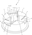
- FIG. 1 to 7 are explanatory diagrams showing the first embodiment of the present invention.
- 9 to 10 are explanatory diagrams showing the second embodiment of the present invention.
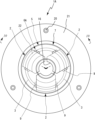
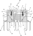
- the top view of the nut of 1st Embodiment. 2-2 line cross-sectional view of FIG.
- FIG. 4 is a schematic cross-sectional view along line 5-5 of FIG. 3;
- a perspective explanatory view of a nut segment Explanatory drawing of the state which inserts a nut segment in a nut main body.
- Explanatory drawing of the state which inserts a bolt Explanatory drawing of the state which inserts a bolt.
- the top view of the nut of 2nd Embodiment. 10-10 line sectional view of FIG. 9.
- FIG. The top view of the nut of 3rd Embodiment. 12-12 line sectional view of FIG.
- FIG. 2 as a reference (front view)
- the upper side will be described as the upper side
- the lower side will be described as the lower side.
- 1 is a nut provided with a plurality of nut segments 2 that slide in the axial direction.
- the nut body 5 of the nut 1 is a short cylinder having a large inner diameter at one end (top end) and a small opening at the other end (bottom). be.
- the nut 1 has a plurality of partition walls 4 provided therein at predetermined intervals in the circumferential direction, and a nut segment housing portion 4 formed by these partition walls.
- a nut body 5 having a plurality of bottom portions with a small diameter, a nut segment 2 which is housed in a nut segment housing portion 4 of the nut body 5 and has a female screw portion 16 formed therein, and the nut segment 2 and a cylindrical shape which will be described later.
- biasing means 6 for biasing the plurality of nut segments 2 toward the bottom surface (downward), and for retaining the nut segments 2 and the biasing means 6 inside the nut body It is composed of a tubular holding means 7 .
- the nut body 5 is made of iron, and as shown in FIGS.
- a plurality of nut segment housings are formed on a part of the wall surface with a downhill inclined surface 8 extending from the upper end surface to the inner wall bottom surface of the bottom, and are partitioned by a total of three partition walls 3 at predetermined intervals in the circumferential direction.
- a part 4 is formed.
- a detachable partition wall 3 may be provided on the nut body 5 .
- a mounting groove or the like may be formed on the inner peripheral surface of the nut body 5, and the partition wall 3 having an engaging piece that engages with the mounting groove may be used for attachment and detachment.
- the partition wall 3 is formed in a substantially fan shape in a plan view, and a short protruding inner end portion 11 continuing from the fan shape portion points toward the center of the inner space of the nut body 5. ing.
- a groove-shaped guide portion 9 is formed on the side surface of the nut segment housing portion 4 side.
- the guide portion 9 is formed in an inclined shape such that the upper end is positioned on the radially outer side and the lower end is positioned on the radially inner side when viewed from the front.
- the inclination angle of the guide portion 9 is formed to be substantially the same angle as the inclined surface 8 formed on the radial wall surface of the nut segment housing portion 4 .
- the guide portion 9 and the inclined surface 8 are substantially parallel.
- a guide piece 10 formed on the nut segment 2 is inserted into the groove-shaped guide portion 9 . By inserting the guide piece 10 into the inclined guide portion 9, it is possible to prevent the nut segment 2 from falling off from the nut body 5 even if the nut body 5 is tilted during assembly.
- a rib-shaped bolt guide portion 11 is formed so as to extend in the vertical direction at the inner corner portion of the partition wall 3 (the corner portion on the center side of the nut body 5).
- the bolt guide portions 11 are formed on the inner corners of the three partitions 3 so as to protrude toward the central corners of the nut body 5 . It is formed so as to have a dimension substantially equal to or slightly larger than the diameter.
- the guide surface 11 a of the bolt guide portion 11 may be a flat surface, but it is preferable to make the guide surface 11 a slightly arcuate along the outer diameter of the bolt 12 .
- this bolt guide portion 11 is positioned below the lower end of the nut segment 2 .
- the lower end of the bolt guide portion 11 may be formed with an inclined surface 11b capable of guiding the bolt 12.
- the partition wall 3 is formed in a generally sectoral shape in a plan view, but it may be formed in a trapezoidal or triangular shape, for example, in which both side portions of the nut segment 2 and the partition wall 3 are substantially in contact with each other, and the bolt guide portion 11 is formed. Any shape can be used as long as it is possible.
- cutouts 13 through which the nut segments 2 can pass are formed on the upper side of the portion of the nut body 5 where the nut segment housing portion 4 is formed. By providing such a notch 13, the nut segment 2 can be inserted into the nut body 5 obliquely from above as shown in FIG.
- the guide piece 10 formed on the nut segment 2 is lengthened, it can be inserted into the guide portion 9, and since the long guide piece 10 and the guide portion 9 contact in a substantially surface contact state, the nut segment 2 does not tilt. can be reliably prevented.
- the nut segment 2 can move upward in a parallel state without rotating.
- a bottom surface of the nut body 5 is formed with a bolt through hole 14 into which a bolt 12 is inserted, and a bottom surface 15 of the nut segment housing portion 4 is formed so that the female screw portions 16 of the adjacent nut segments 2 are continuously connected. is provided with a step. By forming such a step, even if the same nut segment 2 is used, the female threaded portion 16 of the adjacent nut segment 2 is connected so as to be continuously screwed with the male threaded portion of the bolt 12 . can be stored in any nut segment storage portion 4 to function as a nut.
- the nut segment 2 is made of iron, the lower part of its outer peripheral surface is formed in an inclined surface, and the inner peripheral surface is provided with a female screw portion 16 .
- three nut segments are used to form the female screw portion 16 that is screwed with the bolt 12 .
- guide pieces 10 to be inserted into the guide portion 9 are provided on both side surfaces of the nut segment 2 .
- the guide piece 10 is a linear projecting piece having an inclination of approximately the same angle as the guide portion 9. During assembly, as shown in FIG. It is inserted into the guide portion 9 .
- a cap-shaped holding means 7 is fixed to the nut body 5 by caulking, press-fitting, or the like so as to cover the upper portion and outer peripheral portion thereof.
- the outer shape of the nut body 5 is formed to be slightly tapered, and the holding means 7 is fixed to the outer periphery of the nut body 5 by press fitting.
- a biasing means 6 such as a coil spring is provided to always bias the segment 2 downward.
- a plurality of coil springs are used as the urging means 6, and on the upper part of the nut segment 2, there are urging means mounting portions 17 in the form of recesses into which the coil springs 6 can be inserted. Two are formed. The lower ends of the coil springs 6 are inserted into the urging means mounting portions 17, and the upper ends of the coil springs 6 contact the holding means 7 to always urge the nut segments 2 downward.
- the coil spring 6 is in contact with the holding means 7 via the washer 18 .
- This washer 18 may be a normal flat washer 18, but it is desirable to use a washer 18 that corresponds to the step on the bottom surface 15 of the nut segment housing portion 4.
- a washer 18 with a thick plate thickness is used at a portion positioned above the nut segment 2 where the bottom surface has a large step, and a thin plate thickness is used at a portion positioned above the nut segment 2 where there is no step. is desirable.
- the length of the coil spring 6 becomes uniform, and the nut segment 2 can be evenly biased downward.
- the nut segment 2 When the bolt 12 is inserted into the nut 1, the nut segment 2 is lifted obliquely upward, but is pushed downward by the urging means 6 and returns to a substantially initial position without rotating (in a parallel state). ) is screwed with the bolt 12 .
- the nut segment 2 and the nut body 5 are made of iron in this embodiment, they may be made of resin (especially engineering plastics, etc.), alloys, non-ferrous metals, ceramics, or the like.
- the cap-shaped holding means 7 (lid body 7) is fixed by caulking or the like so as to cover the upper portion and outer peripheral portion of the nut body 5 as described above.
- the lid 7 is a cylindrical member having a through hole 19 formed in the center of the upper surface through which a bolt can pass. It is fixed by caulking or the like.
- lid body 7 is made of iron in this embodiment, it may be made of resin, non-ferrous metal, alloy, ceramics, or the like.
- a washer 21 having a screw hole 20 for fixing the nut 1 to a piece of wood or the like is rotatably attached near the lower end of the nut body 5 .
- the nut 1 of the present invention is used, for example, in wooden houses, steel structures, concrete structures, and the like. In addition to this, it can be used for various equipment such as space, aviation, and navigation equipment.
- the nut segment 2 Since the nut segment 2 is guided by the guide portion 9 and the guide piece 10 when the nut segment 2 moves in this way, the nut segment 2 is slid only in the linear direction along the inclination of the guide portion 9, and the nut segment 2 can be smoothly moved upward without rotating.
- the partition wall is formed in a substantially sectoral shape in a plan view, even if the nut segment 2 is lifted in the direction in which the diameter of the female screw portion 16 widens, both side portions of the nut segment 2 and the partition wall 3 are always substantially in contact with each other. It is possible to prevent the guide piece 10 from falling off from the guide portion 9 and moving upward without being guided by the guide portion 9. - ⁇
- the bolt 12 is guided so as to be substantially perpendicular to the nut 1, and the nut segment 2 is pushed upward without rotating by the guide portion 9 and the guide piece 10, whereby the female screw portion 16 is biting the bolt 12 or being caught on the bolt 12 at an unintended position, preventing the bolt 12 from smoothly penetrating the nut 1.
- the nut segment 2 is designed so as not to move upward by more than 1.5 threads of the female screw portion 16 .
- the nut segment 2 moves upward. Since the nut segment 2 moves accurately one thread at a time, even if the bolt 12 is properly pushed in and stopped, the plurality of nut segments 2 can be accurately moved. Combine with bolt pitch.
- the bolt 12 penetrates the nut 1 when the diameter of the female threaded portion 16 increases to the extent that the bolt 12 can pass through. In such a state, the nut 1 is turned in the tightening direction, and the nut 1 and the bolt 12 are tightly tightened.
- the female threaded portion 16 of the nut segment 2 and the male threaded portion of the bolt 12 may not mesh with each other, causing the nut segment 2 to float.
- the female threaded portion 16 of the nut segment 2 and the male threaded portion of the bolt 12 are securely engaged. be able to.
- the nut body 5 and the like are circular in plan view (the outer shape is cylindrical), a jig mounting portion (not shown) is provided on the nut body 5 and the like, and retightening and the like are performed via the jig. Good.
- the outer shape of the nut body 5 and the lid body 7 may be polygonal such as a hexagon in plan view, and configured to be tightened with a wrench or the like.
- an engagement piece (not shown) may be provided at the bottom of the nut body 5 of the nut 1, and a washer member may be engaged with the engagement piece to fix the nut 1 to a piece of wood or the like.
- the main difference from the first embodiment for carrying out the invention is that the inner diameter of the bolt 12 is larger than the diameter of the bolt 12 .
- the use of the biasing means 6A comprising the coil spring 22 and the pressing plate 23 whose bottom surface is formed in a stepped manner so as to abut on the upper surface of the nut segment 2 is advantageous. Even with the nut 1A used, the same effects as those of the first embodiment can be obtained.
- the main difference from the first embodiment for carrying out the present invention is that the claws 24 are provided by welding, sheet metal processing, or the like. Since the washer 21A is used, the nut 1B can have the same effect as the first embodiment, and the nut 1B can be directly fixed to the wood without using screws or the like. can be done.
- linear guide portion is formed in the partition wall
- a concave guide portion may be formed in the partition wall.
- a guide piece may be formed on the outer surface of the nut segment. In such a case, it is not necessary to form a notch in the nut body.
- a washer having a screw hole or claw is provided, other known washers may be used, or a nut without a washer may be used.
- the present invention is used in the industry that manufactures nuts.
- 1, 1A, 1B nuts, 2: nut segments, 3: partition wall, 4: nut segment housing, 5: nut body, 6, 6A: biasing means, 7: holding means, 8: inclined surface, 9: guide part, 10: guide piece, 11: bolt guide portion, 12: bolt, 13: Notch, 14: Bolt through hole, 15: Bottom, 16: Female screw part, 17: urging means mounting portion, 18: washer, 19: through hole, 20: screw hole, 21: washer, 22: coil spring, 23: pressing plate, 24: claw.
Landscapes
- Engineering & Computer Science (AREA)
- General Engineering & Computer Science (AREA)
- Mechanical Engineering (AREA)
- Lining And Supports For Tunnels (AREA)
Abstract
La présente invention aborde le problème de la production d'un écrou se vissant avec aisance sur un boulon, sans inclination d'un segment de l'écrou ou du boulon lorsque le boulon est introduit. À cet effet, la présente invention concerne un écrou (1) comprenant : un corps (5) d'écrou comportant une pluralité de parois de séparation (3) disposées intérieurement à des intervalles prescrits dans la direction circonférentielle, et une pluralité de parties (4) de réception de segment d'écrou formées par lesdites parois de séparation (3); et une pluralité de segments (2) d'écrou reçus chacun dans une partie (4) de réception de segment d'écrou respective. Une marche est formée dans une surface inférieure (15) formant les parties (4) de réception de segment d'écrou, une partie de guidage (9) est formée dans les parties (4) de réception de segment d'écrou, et les segments (2) d'écrou sont munis d'une pièce de guidage (10) faisant coulisser les segments (2) d'écrou. Une partie (11) de guidage de boulon, permettant d'introduire le boulon dans le segment (2) d'écrou selon un angle sensiblement droit, est formée au niveau d'une section d'extrémité interne des parois de séparation (3) faisant saillie radialement vers l'intérieur.
Priority Applications (1)
| Application Number | Priority Date | Filing Date | Title |
|---|---|---|---|
| PCT/JP2021/041882 WO2023084768A1 (fr) | 2021-11-15 | 2021-11-15 | Écrou |
Applications Claiming Priority (1)
| Application Number | Priority Date | Filing Date | Title |
|---|---|---|---|
| PCT/JP2021/041882 WO2023084768A1 (fr) | 2021-11-15 | 2021-11-15 | Écrou |
Publications (1)
| Publication Number | Publication Date |
|---|---|
| WO2023084768A1 true WO2023084768A1 (fr) | 2023-05-19 |
Family
ID=86335460
Family Applications (1)
| Application Number | Title | Priority Date | Filing Date |
|---|---|---|---|
| PCT/JP2021/041882 Ceased WO2023084768A1 (fr) | 2021-11-15 | 2021-11-15 | Écrou |
Country Status (1)
| Country | Link |
|---|---|
| WO (1) | WO2023084768A1 (fr) |
Citations (8)
| Publication number | Priority date | Publication date | Assignee | Title |
|---|---|---|---|---|
| US3151652A (en) * | 1958-02-26 | 1964-10-06 | Victor F Zahodiakin | Fastening devices |
| JPS5311273A (en) * | 1976-07-16 | 1978-02-01 | Mitsutomo Kk | Nut |
| JPH1037933A (ja) * | 1996-07-29 | 1998-02-13 | Yazaki Corp | バンドクランプ |
| JP2012211648A (ja) * | 2011-03-31 | 2012-11-01 | Piolax Inc | ボルトクリップ |
| JP2013061036A (ja) * | 2011-09-14 | 2013-04-04 | Nifco Inc | 留め具 |
| JP2013234731A (ja) * | 2012-05-10 | 2013-11-21 | Kaoru Taneichi | 押し込みナット |
| US20140130609A1 (en) * | 2011-02-07 | 2014-05-15 | Ronald A. Smith | Thread clamping device including internal sensing, reporting and external detector |
| JP6931703B2 (ja) * | 2017-08-03 | 2021-09-08 | 種市 薫 | ナット |
-
2021
- 2021-11-15 WO PCT/JP2021/041882 patent/WO2023084768A1/fr not_active Ceased
Patent Citations (8)
| Publication number | Priority date | Publication date | Assignee | Title |
|---|---|---|---|---|
| US3151652A (en) * | 1958-02-26 | 1964-10-06 | Victor F Zahodiakin | Fastening devices |
| JPS5311273A (en) * | 1976-07-16 | 1978-02-01 | Mitsutomo Kk | Nut |
| JPH1037933A (ja) * | 1996-07-29 | 1998-02-13 | Yazaki Corp | バンドクランプ |
| US20140130609A1 (en) * | 2011-02-07 | 2014-05-15 | Ronald A. Smith | Thread clamping device including internal sensing, reporting and external detector |
| JP2012211648A (ja) * | 2011-03-31 | 2012-11-01 | Piolax Inc | ボルトクリップ |
| JP2013061036A (ja) * | 2011-09-14 | 2013-04-04 | Nifco Inc | 留め具 |
| JP2013234731A (ja) * | 2012-05-10 | 2013-11-21 | Kaoru Taneichi | 押し込みナット |
| JP6931703B2 (ja) * | 2017-08-03 | 2021-09-08 | 種市 薫 | ナット |
Similar Documents
| Publication | Publication Date | Title |
|---|---|---|
| US10054149B2 (en) | Dual sliding wedge T-nut | |
| EP0905390A2 (fr) | Ecrou de blocage | |
| US5219449A (en) | Pipe connector | |
| US9353778B2 (en) | Screw connection | |
| WO2008129854A1 (fr) | Dispositif de fixation | |
| JP2022051563A (ja) | 特に板状の、少なくとも2つの要素を接続するための接続システム、そのような接続システムを備える構成 | |
| JP5912829B2 (ja) | 押し込みナット | |
| WO2023084768A1 (fr) | Écrou | |
| GB2039659A (en) | Coupling device for furniture panels | |
| JP2698974B2 (ja) | 自動車の前照灯における反射鏡傾斜角の調節装置 | |
| US20050061099A1 (en) | Ball-nut assembly and method for making | |
| JP6931703B2 (ja) | ナット | |
| JP6573422B2 (ja) | 配線機器類の取着装置及び機器支持具 | |
| US7354217B2 (en) | Fastening device and method for attaching an object to a support structure | |
| JP2007530879A (ja) | ネジボルトを備えた支持部材に固定するための装置 | |
| JP6324464B2 (ja) | 控え金具 | |
| JP3027084U (ja) | 金属薄板ねじ込取付用スペーサ | |
| JPH0726653Y2 (ja) | 整準ねじの倒れガタ防止装置 | |
| CA2224028C (fr) | Pince de positionnement et methode de fabrication connexe | |
| KR19990022811U (ko) | 파이프클램프의베이스플레이트 | |
| US20250283500A1 (en) | Nut | |
| JPS58178007A (ja) | 軽量ナツト | |
| JP2023167642A (ja) | ナット | |
| JPH0354968Y2 (fr) | ||
| JP7324636B2 (ja) | 支柱接続構造 |
Legal Events
| Date | Code | Title | Description |
|---|---|---|---|
| 121 | Ep: the epo has been informed by wipo that ep was designated in this application |
Ref document number: 21964121 Country of ref document: EP Kind code of ref document: A1 |
|
| 122 | Ep: pct application non-entry in european phase |
Ref document number: 21964121 Country of ref document: EP Kind code of ref document: A1 |
|
| NENP | Non-entry into the national phase |
Ref country code: JP |