WO2023084902A1 - 多段逆浸透膜処理システム - Google Patents
多段逆浸透膜処理システム Download PDFInfo
- Publication number
- WO2023084902A1 WO2023084902A1 PCT/JP2022/034165 JP2022034165W WO2023084902A1 WO 2023084902 A1 WO2023084902 A1 WO 2023084902A1 JP 2022034165 W JP2022034165 W JP 2022034165W WO 2023084902 A1 WO2023084902 A1 WO 2023084902A1
- Authority
- WO
- WIPO (PCT)
- Prior art keywords
- reverse osmosis
- water
- osmosis membrane
- treated
- treatment system
- Prior art date
- Legal status (The legal status is an assumption and is not a legal conclusion. Google has not performed a legal analysis and makes no representation as to the accuracy of the status listed.)
- Ceased
Links
Images



Classifications
-
- C—CHEMISTRY; METALLURGY
- C02—TREATMENT OF WATER, WASTE WATER, SEWAGE, OR SLUDGE
- C02F—TREATMENT OF WATER, WASTE WATER, SEWAGE, OR SLUDGE
- C02F1/00—Treatment of water, waste water, or sewage
- C02F1/44—Treatment of water, waste water, or sewage by dialysis, osmosis or reverse osmosis
-
- B—PERFORMING OPERATIONS; TRANSPORTING
- B01—PHYSICAL OR CHEMICAL PROCESSES OR APPARATUS IN GENERAL
- B01D—SEPARATION
- B01D61/00—Processes of separation using semi-permeable membranes, e.g. dialysis, osmosis or ultrafiltration; Apparatus, accessories or auxiliary operations specially adapted therefor
- B01D61/02—Reverse osmosis; Hyperfiltration ; Nanofiltration
- B01D61/025—Reverse osmosis; Hyperfiltration
- B01D61/026—Reverse osmosis; Hyperfiltration comprising multiple reverse osmosis steps
-
- B—PERFORMING OPERATIONS; TRANSPORTING
- B01—PHYSICAL OR CHEMICAL PROCESSES OR APPARATUS IN GENERAL
- B01D—SEPARATION
- B01D61/00—Processes of separation using semi-permeable membranes, e.g. dialysis, osmosis or ultrafiltration; Apparatus, accessories or auxiliary operations specially adapted therefor
- B01D61/02—Reverse osmosis; Hyperfiltration ; Nanofiltration
- B01D61/04—Feed pretreatment
-
- B—PERFORMING OPERATIONS; TRANSPORTING
- B01—PHYSICAL OR CHEMICAL PROCESSES OR APPARATUS IN GENERAL
- B01D—SEPARATION
- B01D61/00—Processes of separation using semi-permeable membranes, e.g. dialysis, osmosis or ultrafiltration; Apparatus, accessories or auxiliary operations specially adapted therefor
- B01D61/02—Reverse osmosis; Hyperfiltration ; Nanofiltration
- B01D61/08—Apparatus therefor
-
- B—PERFORMING OPERATIONS; TRANSPORTING
- B01—PHYSICAL OR CHEMICAL PROCESSES OR APPARATUS IN GENERAL
- B01D—SEPARATION
- B01D61/00—Processes of separation using semi-permeable membranes, e.g. dialysis, osmosis or ultrafiltration; Apparatus, accessories or auxiliary operations specially adapted therefor
- B01D61/02—Reverse osmosis; Hyperfiltration ; Nanofiltration
- B01D61/12—Controlling or regulating
-
- C—CHEMISTRY; METALLURGY
- C02—TREATMENT OF WATER, WASTE WATER, SEWAGE, OR SLUDGE
- C02F—TREATMENT OF WATER, WASTE WATER, SEWAGE, OR SLUDGE
- C02F1/00—Treatment of water, waste water, or sewage
- C02F1/44—Treatment of water, waste water, or sewage by dialysis, osmosis or reverse osmosis
- C02F1/441—Treatment of water, waste water, or sewage by dialysis, osmosis or reverse osmosis by reverse osmosis
-
- C—CHEMISTRY; METALLURGY
- C02—TREATMENT OF WATER, WASTE WATER, SEWAGE, OR SLUDGE
- C02F—TREATMENT OF WATER, WASTE WATER, SEWAGE, OR SLUDGE
- C02F1/00—Treatment of water, waste water, or sewage
- C02F1/66—Treatment of water, waste water, or sewage by neutralisation; pH adjustment
-
- B—PERFORMING OPERATIONS; TRANSPORTING
- B01—PHYSICAL OR CHEMICAL PROCESSES OR APPARATUS IN GENERAL
- B01D—SEPARATION
- B01D2311/00—Details relating to membrane separation process operations and control
- B01D2311/04—Specific process operations in the feed stream; Feed pretreatment
-
- B—PERFORMING OPERATIONS; TRANSPORTING
- B01—PHYSICAL OR CHEMICAL PROCESSES OR APPARATUS IN GENERAL
- B01D—SEPARATION
- B01D2311/00—Details relating to membrane separation process operations and control
- B01D2311/18—Details relating to membrane separation process operations and control pH control
-
- B—PERFORMING OPERATIONS; TRANSPORTING
- B01—PHYSICAL OR CHEMICAL PROCESSES OR APPARATUS IN GENERAL
- B01D—SEPARATION
- B01D2311/00—Details relating to membrane separation process operations and control
- B01D2311/24—Quality control
- B01D2311/246—Concentration control
-
- B—PERFORMING OPERATIONS; TRANSPORTING
- B01—PHYSICAL OR CHEMICAL PROCESSES OR APPARATUS IN GENERAL
- B01D—SEPARATION
- B01D2317/00—Membrane module arrangements within a plant or an apparatus
- B01D2317/02—Elements in series
- B01D2317/025—Permeate series
-
- B—PERFORMING OPERATIONS; TRANSPORTING
- B01—PHYSICAL OR CHEMICAL PROCESSES OR APPARATUS IN GENERAL
- B01D—SEPARATION
- B01D2325/00—Details relating to properties of membranes
- B01D2325/20—Specific permeability or cut-off range
-
- C—CHEMISTRY; METALLURGY
- C02—TREATMENT OF WATER, WASTE WATER, SEWAGE, OR SLUDGE
- C02F—TREATMENT OF WATER, WASTE WATER, SEWAGE, OR SLUDGE
- C02F2101/00—Nature of the contaminant
- C02F2101/10—Inorganic compounds
- C02F2101/108—Boron compounds
-
- C—CHEMISTRY; METALLURGY
- C02—TREATMENT OF WATER, WASTE WATER, SEWAGE, OR SLUDGE
- C02F—TREATMENT OF WATER, WASTE WATER, SEWAGE, OR SLUDGE
- C02F2103/00—Nature of the water, waste water, sewage or sludge to be treated
- C02F2103/08—Seawater, e.g. for desalination
-
- C—CHEMISTRY; METALLURGY
- C02—TREATMENT OF WATER, WASTE WATER, SEWAGE, OR SLUDGE
- C02F—TREATMENT OF WATER, WASTE WATER, SEWAGE, OR SLUDGE
- C02F2209/00—Controlling or monitoring parameters in water treatment
- C02F2209/06—Controlling or monitoring parameters in water treatment pH
-
- C—CHEMISTRY; METALLURGY
- C02—TREATMENT OF WATER, WASTE WATER, SEWAGE, OR SLUDGE
- C02F—TREATMENT OF WATER, WASTE WATER, SEWAGE, OR SLUDGE
- C02F2301/00—General aspects of water treatment
- C02F2301/08—Multistage treatments, e.g. repetition of the same process step under different conditions
-
- Y—GENERAL TAGGING OF NEW TECHNOLOGICAL DEVELOPMENTS; GENERAL TAGGING OF CROSS-SECTIONAL TECHNOLOGIES SPANNING OVER SEVERAL SECTIONS OF THE IPC; TECHNICAL SUBJECTS COVERED BY FORMER USPC CROSS-REFERENCE ART COLLECTIONS [XRACs] AND DIGESTS
- Y02—TECHNOLOGIES OR APPLICATIONS FOR MITIGATION OR ADAPTATION AGAINST CLIMATE CHANGE
- Y02A—TECHNOLOGIES FOR ADAPTATION TO CLIMATE CHANGE
- Y02A20/00—Water conservation; Efficient water supply; Efficient water use
- Y02A20/124—Water desalination
- Y02A20/131—Reverse-osmosis
Definitions
- the present invention relates to a multi-stage reverse osmosis membrane treatment system, and more particularly to a multi-stage reverse osmosis membrane treatment system capable of obtaining treated water of a predetermined level of water quality while suppressing operating energy.
- pure water such as ultrapure water from which organic substances, ionic components, fine particles, bacteria, etc. have been highly removed has been used as cleaning water in the manufacturing process of semiconductor devices and the manufacturing process of liquid crystal display devices.
- pure water production system with an exchange device is used.
- the reverse osmosis membrane consumes a large amount of power, it is not necessarily suitable for recent energy saving demands.
- a first reverse osmosis membrane treatment means for passing water to be treated through a first reverse osmosis membrane to obtain a first permeated water and a first concentrated water, and at least the first permeated water through the second reverse osmosis membrane to obtain a second permeated water and a second concentrated water, and a permeation flux per 1 MPa of effective pressure of the second reverse osmosis membrane is lower than the permeation flux per 1 MPa of effective pressure of the first reverse osmosis membrane, and the permeation flux per 1 MPa of effective pressure of the second reverse osmosis membrane is 0.5 m 3 /m 2 /d or less
- An osmotic membrane treatment system has been proposed.
- the reverse osmosis membrane treatment system described in Patent Document 1 aims to improve water quality by removing IPA from the permeated water, and has a problem that the effect of suppressing operating energy is low. Therefore, it is conceivable to use a combination of reverse osmosis membranes with low operating energy, but there is a problem that it is difficult to obtain treated water from which weakly acidic ion species such as boron and silica are sufficiently removed.
- the present invention has been made in view of the above problems, and an object of the present invention is to provide a multi-stage reverse osmosis membrane treatment system capable of obtaining treated water of a predetermined level of water quality while suppressing operating energy.
- the present invention provides a multi-stage reverse osmosis membrane treatment system in which two or more stages of reverse osmosis membranes are arranged in series, wherein at least one of the two or more stages of reverse osmosis membranes has a membrane surface effective pressure of 1 MPa (water temperature A reverse osmosis membrane (hereinafter referred to as a first reverse osmosis membrane) having a permeation flux of 2.0 m 3 /(m 2 ⁇ day) or more per pure water (RO permeate water) at 25 ° C., A multi-stage reverse osmosis membrane treatment system for adjusting the pH of water to be treated by the reverse osmosis membranes to the alkaline side.
- a reverse osmosis membrane (hereinafter referred to as a first reverse osmosis membrane) having a permeation flux of 2.0 m 3 /(m 2 ⁇ day) or more per pure water (RO permeate water) at 25 ° C.
- invention 1 in a pure water production system equipped with an ion exchange device, weakly acidic ion species such as boron and silica derived from feed water are difficult to remove in the ion exchange device, and boron and silica leak. easily occur. Therefore, reverse osmosis membranes are provided in multiple stages in front of this ion exchange device, which increases the operating energy of the pure water production system.
- this invention by using a reverse osmosis membrane (first reverse osmosis membrane) having a large permeation flux per 1 MPa of membrane surface effective pressure (small membrane surface effective pressure at the same permeation flux), It is possible to significantly reduce the operating energy (for example, 20% or more) compared to the case where a multi-stage reverse osmosis membrane treatment system is configured only with reverse osmosis membranes having a permeation flux smaller than this.
- the pH of the water supply (water to be treated) of the first reverse osmosis membrane to the alkaline side for treatment, the removal rate of boron and silica can be maintained at a predetermined level or higher. As a result, it is possible to achieve both suppression of driving energy and water quality.
- the first reverse osmosis membranes are arranged in two stages in series, and the pH of the water to be treated in one of the first reverse osmosis membranes is adjusted to the alkaline side for treatment. is preferred (Invention 2).
- the first reverse osmosis membranes having a low membrane surface effective pressure are connected in two stages in series to form a multistage reverse osmosis membrane treatment system, thereby further reducing the operating energy. can.
- a reverse osmosis membrane having a permeation flux of 0.8 m 3 /(m 2 day) or more per membrane surface effective pressure 1 MPa (water temperature 25 ° C., pure water (RO permeate water)) (hereinafter referred to as a second reverse osmosis membrane) and the first reverse osmosis membrane are arranged in series, and the pH of the water to be treated by the first reverse osmosis membrane is adjusted to the alkaline side for treatment.
- a reverse osmosis membrane having a permeation flux of 0.8 m 3 /(m 2 day) or more per membrane surface effective pressure 1 MPa water temperature 25 ° C., pure water (RO permeate water)
- the operating energy is reduced by combining the first reverse osmosis membrane having a large permeation flux per 1 MPa of membrane surface effective pressure and the reverse osmosis membrane having a smaller permeation flux. While suppressing to some extent, the removal rate of boron and silica can be improved.
- the water quality of the water to be treated in the multistage reverse osmosis membrane treatment system preferably has a boron concentration of 1 to 500 ⁇ g/L and/or a silica concentration of 1 to 50 mg/L ( Invention 4).
- invention 4 by treating the water to be treated with the above boron concentration and silica concentration with a multi-stage reverse osmosis membrane treatment system, boron and silica in the treated water can be removed at a high level of 95% or more. can be done.
- the permeation flux is It is possible to significantly reduce the operating energy (for example, 20% or more) compared to the case of combining only reverse osmosis membranes lower than . Furthermore, by adjusting the pH of the feed water of the first reverse osmosis membrane to the alkaline side and treating it, the boron and silica removal rate can be maintained at a predetermined level or higher. As a result, it is possible to provide a multi-stage reverse osmosis membrane treatment system that achieves both suppression of operating energy and water quality.
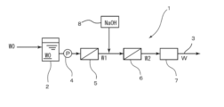
- FIG. 1 is a flow diagram showing a pure water production apparatus using a multi-stage reverse osmosis membrane treatment system according to the first embodiment of the present invention
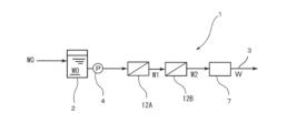
- FIG. 4 is a flowchart showing a pure water production apparatus using a multistage reverse osmosis membrane treatment system according to a second embodiment of the present invention
- FIG. 3 is a flow diagram showing a pure water production apparatus using a multistage reverse osmosis membrane treatment system according to a third embodiment of the present invention
- 2 is a flow chart showing a pure water production apparatus using a multi-stage reverse osmosis membrane treatment system of Comparative Example 1.
- FIG. 10 is a flow diagram showing a pure water production apparatus using a multi-stage reverse osmosis membrane treatment system of Comparative Example 2;
- FIG. 10 is a flow diagram showing a pure water production apparatus using a multi-stage reverse osmosis membrane treatment system of Comparative Example 3;
- FIG. 1 shows a pure water production apparatus using a multi-stage reverse osmosis membrane treatment system according to a first embodiment of the present invention.
- a pure water production apparatus 1 includes a storage tank 2 for storing water to be treated W0 as raw water, and a water pipe 3 connected to the storage tank 2.
- the water pipe 3 is equipped with a liquid feed pump. 4, a second reverse osmosis membrane 5, a first reverse osmosis membrane 6, and an ion exchange device 7 are provided in sequence.
- NaOH aqueous solution addition means 8 as an alkali addition mechanism is connected to the front stage of the first reverse osmosis membrane 6, and a control mechanism (not shown) controls the flow rate of the water flow pipe 3 and the pH of the water to be treated W0. Accordingly, the addition amount of the NaOH solution can be controlled so that the water to be treated of the first reverse osmosis membrane 6 is in the alkaline region.
- the second reverse osmosis membrane 5, the first reverse osmosis membrane 6 and the NaOH aqueous solution adding means 8 constitute a multi-stage reverse osmosis membrane treatment system.
- the first reverse osmosis membrane to the third reverse osmosis membrane shall have the following performances. There are reverse osmosis membranes having a smaller permeation flux per 1 MPa of membrane surface effective pressure than the first to third reverse osmosis membranes, but these are general reverse osmosis membranes.
- the ion exchange device 7 is not particularly limited as long as it has the ability to remove ionic components (anions and cations) in the water to be treated.
- An ion exchange apparatus, a non-regenerative mixed bed ion exchange apparatus, or the like can be used, but in this embodiment, a regenerative ion exchange apparatus is used.
- the water to be treated W ⁇ b>0 stored in the storage tank 2 is supplied to the second reverse osmosis membrane 5 by driving the liquid feed pump 4 .
- the water to be treated W0 preferably has a boron concentration of 1 to 500 ⁇ g/L and/or a silica concentration of 1 to 50 mg/L.
- the second reverse osmosis membrane 5 removes ionic impurities to some extent to obtain primary treated water W1.
- the supply pressure of the water to be treated W0 from the liquid feed pump 4 may be set based on the configuration of the reverse osmosis membrane and the desired permeation flux.
- the second reverse osmosis membrane 5 has a permeation flux of 1.0 m 3 /(m 2 ⁇ day), using a reverse osmosis membrane with a permeation flux of 1.00 m 3 / (m 2 day) per membrane surface effective pressure 1 MPa (water temperature 25 ° C., pure water (RO permeate water)), the first reverse osmosis membrane As 6, permeation flux (flux) 0.76 m 3 / (m 2 ⁇ day) or more under the condition of membrane surface effective pressure 0.3 MPa (water temperature 25 ° C, pure water (RO permeate water)), membrane surface effective pressure When using a reverse osmosis membrane with a permeation flux of 2.53 m 3 /(m 2 day) per 1 MPa (water temperature 25 ° C., pure water (RO permeate water)), the second reverse osmosis membrane 5 and the first When water is passed through the reverse osmosis membrane 6 at a permeation flux (flux) of 1
- the NaOH aqueous solution addition means 8 adds an NaOH aqueous solution to the primary treated water W1 to adjust the pH of the primary treated water W1 to be treated by the first reverse osmosis membrane 6 to the alkaline side. Specifically, it is preferable to set the pH of the primary treated water W1 to 8-11. By setting the pH of the primary treated water W1 to 8 to 11, the removal rate of weakly acidic ion species such as boron and silica remaining in the primary treated water W1 can be improved. By treating the water with the first reverse osmosis membrane 6, remaining ionic impurities, particularly boron and silica, are removed to obtain secondary treated water W2.
- pure water W can be produced by treating this secondary treated water W2 with the ion exchange device 7 to further remove remaining ionic impurities.
- the first reverse osmosis membrane 6 having a permeation flux of 2.0 m 3 /(m 2 ⁇ day) or more per effective pressure of 1 MPa is used, and this Since the pH of the primary treated water W1 to be treated by the first reverse osmosis membrane 6 is adjusted to the alkaline side, the boron and silica removal rate of the pure water W obtained is maintained at a high level (eg, 95% or more). can do.
- the operating energy of the multistage reverse osmosis membrane treatment system is approximately proportional to the feed pressure of the water to be treated W0 from the liquid sending pump 4, that is, the output of the liquid sending pump 4, the magnitude of the operating energy can be compared based on this. can be done.
- the water supply pressure of the liquid transfer pump 4 is theoretically 1.5 when the second reverse osmosis membrane is provided in two stages in series. Since it is ( ⁇ 0.75 ⁇ 2) MPa, the operating energy reduction rate is about 27% ((1.5 ⁇ 1.1)/1.5 ⁇ 100 ⁇ 27).
- FIG. 2 shows a pure water production apparatus using a multi-stage reverse osmosis membrane treatment system according to the second embodiment of the present invention, which basically has the same configuration as the first embodiment described above. are denoted by the same reference numerals, and detailed description thereof will be omitted.
- the first reverse osmosis membranes 6A, 6B, and 6C are arranged in series in three stages in the water pipe 3, and NaOH is provided in the preceding stage of the first reverse osmosis membrane 6B in the second stage. It has a configuration in which an aqueous solution adding means 8 is provided.
- the first reverse osmosis membranes 6A, 6B, 6C and the NaOH aqueous solution adding means 8 constitute a multi-stage reverse osmosis membrane treatment system.
- the liquid feed pump 4 is driven to supply the water to be treated W0 stored in the storage tank 2 to the first reverse osmosis membrane 6A.
- the water to be treated W0 preferably has a boron concentration of 1 to 500 ⁇ g/L and/or a silica concentration of 1 to 50 mg/L. Ionic impurities are removed to some extent by the first reverse osmosis membrane 6A to obtain primary treated water W1.
- the water supply pressure of the water to be treated W0 from the liquid feed pump 4 at this time may be set in consideration of the construction of the reverse osmosis membranes 6A, 6B, 6C.
- each It may be set to 1.2 ( ⁇ 0.39 ⁇ 3) MPa based on the membrane surface effective pressure.
- an NaOH aqueous solution is added to the primary treated water W1 by the NaOH aqueous solution adding means 8 to adjust the pH of the primary treated water W1 to the alkaline side.
- the removal rate of weakly acidic ion species such as boron and silica remaining in the primary treated water W1 can be improved.
- the secondary treated water W2 is treated with the first reverse osmosis membrane 6C of the third stage to further remove the remaining ionic impurities to obtain the tertiary treated water W3.
- first reverse osmosis membranes 6A, 6B, 6C are combined in three stages in series and primary treated water W1 treated by the first reverse osmosis membrane 6B in the second stage is adjusted to the alkaline side, the boron and silica removal rate of the pure water W to be obtained can be maintained at 95% or more.
- FIG. 3 shows a pure water production apparatus using a multi-stage reverse osmosis membrane treatment system according to the third embodiment of the present invention, which basically has the same configuration as the first embodiment described above. are denoted by the same reference numerals, and detailed description thereof will be omitted.
- the first reverse osmosis membranes 6D and 6E are provided in two stages in series in the water pipe 3, and an alkali addition mechanism is provided before the first reverse osmosis membrane 6D in the first stage. It has a configuration in which NaOH aqueous solution addition means 8 is provided as.
- the first reverse osmosis membranes 6D and 6E and the NaOH aqueous solution adding means 8 constitute a multi-stage reverse osmosis membrane treatment system.
- the liquid feed pump 4 is driven to supply the water to be treated W0 stored in the storage tank 2 to the first reverse osmosis membrane 6D.
- the water to be treated W0 preferably has a boron concentration of 1 to 500 ⁇ g/L and/or a silica concentration of 1 to 50 mg/L.
- the water supply pressure of the water to be treated W0 from the liquid feed pump 4 at this time may be set in consideration of the construction of the reverse osmosis membranes 6D and 6E.
- each membrane It may be set to 0.8 ( ⁇ 0.39 ⁇ 2) MPa based on the surface effective pressure.
- the NaOH aqueous solution is added to the water W0 to be treated from the NaOH aqueous solution adding means 8 to adjust the pH of the water to be treated W0 to the alkaline side.
- the removal rate of weakly acidic ion species such as boron and silica present in the water to be treated W0 can be improved.
- the secondary treated water W2 is treated with the ion exchange device 7 to further remove remaining ionic impurities, thereby producing pure water W.
- the multistage reverse osmosis membrane treatment system of the present embodiment under the condition of a membrane surface effective pressure of 0.3 MPa (water temperature of 25 ° C., pure water (RO permeate water)), permeation flux per effective pressure of 1 MPa Only the first reverse osmosis membrane 6 having a capacity of 2.00 m 3 /(m 2 ⁇ day) or more is combined, and the pH of the primary treated water W1 to be treated with the first stage first reverse osmosis membrane 6D is adjusted to the alkaline side. Therefore, the removal rate of boron and silica in the pure water W obtained can be maintained at 95% or more.
- the present invention has been described above based on the above embodiments, the present invention is not limited to the above embodiments, and various modifications are possible.
- the present invention uses a first reverse osmosis membrane as one of the reverse osmosis membranes in a multi-stage reverse osmosis membrane treatment system in which multiple reverse osmosis membranes are connected in series, and the liquid to be treated in the preceding stage may be adjusted to the alkaline side, and the first reverse osmosis membrane and the third reverse osmosis membrane may be combined.
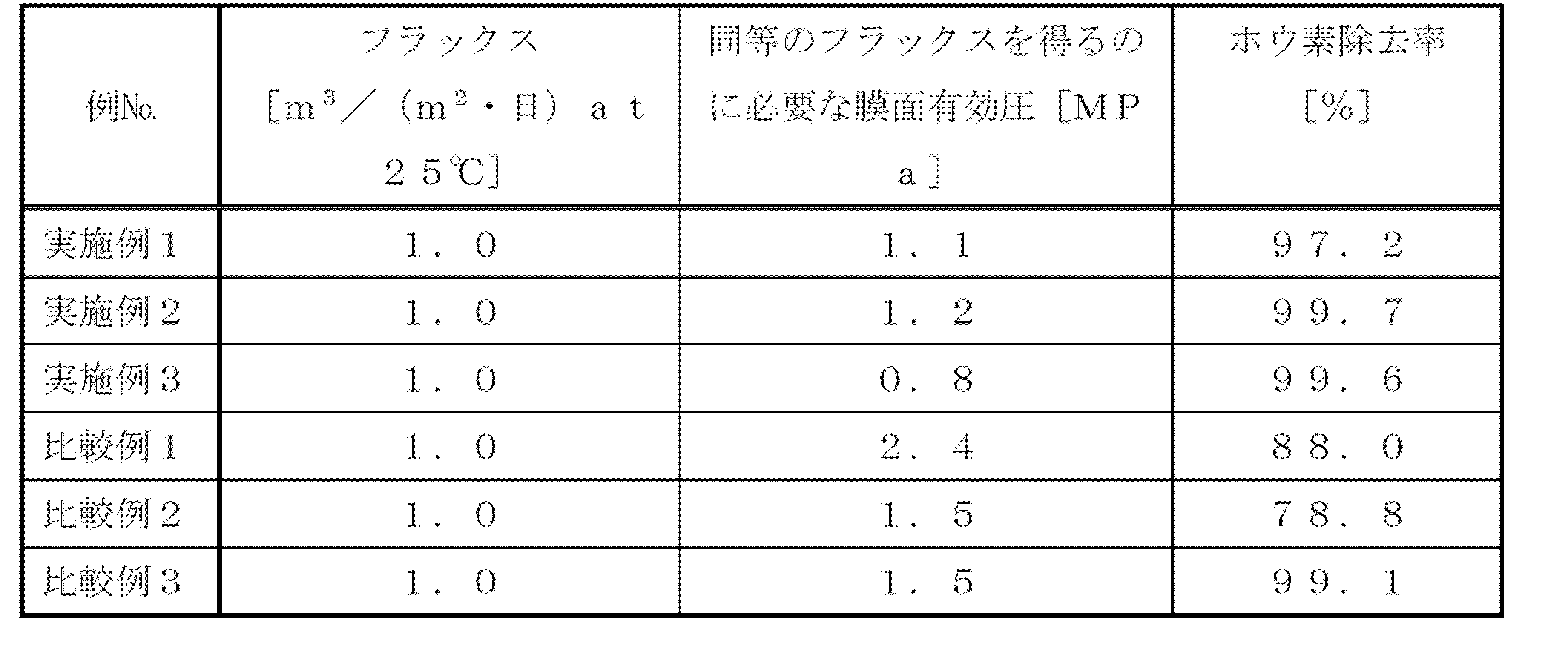
- Example 1 In the pure water production apparatus using the multi-stage reverse osmosis membrane treatment system shown in FIG . Day) at 25° C.), and the pure water production apparatus 1 was operated with the pH adjusted to 11 in the stage preceding the first reverse osmosis membrane 6 . At this time, the boron removal rate was calculated based on the measurement result of the boron concentration in the preceding stage of the ion exchange device 7 (outlet of the reverse osmosis membrane in the last stage). The results are shown in Table 2 together with the flux and the membrane surface effective pressure required to obtain the equivalent flux.
- Example 2 In the pure water production apparatus using the multi-stage reverse osmosis membrane treatment system shown in FIG . Day) at 25° C.), and the pure water production apparatus 1 was operated with the pH adjusted to 11 in the preceding stage of the first reverse osmosis membrane 6B. The urinary removal rate was calculated based on the measurement result of the boron concentration in the preceding stage (reverse osmosis membrane outlet of the last stage) of the ion exchange device 7 at this time. The results are shown in Table 2 together with the flux and the membrane surface effective pressure required to obtain the equivalent flux.
- Example 3 In the pure water production apparatus using the multi-stage reverse osmosis membrane treatment system shown in FIG . Day) at 25° C.), and the pure water production apparatus 1 was operated with the pH adjusted to 11 in the preceding stage of the first reverse osmosis membrane 6D. The urinary removal rate was calculated based on the measurement result of the boron concentration in the preceding stage (reverse osmosis membrane outlet of the last stage) of the ion exchange device 7 at this time. The results are shown in Table 2 together with the flux and the membrane surface effective pressure required to obtain the equivalent flux.
Landscapes
- Chemical & Material Sciences (AREA)
- Engineering & Computer Science (AREA)
- Water Supply & Treatment (AREA)
- Nanotechnology (AREA)
- Chemical Kinetics & Catalysis (AREA)
- Life Sciences & Earth Sciences (AREA)
- Hydrology & Water Resources (AREA)
- Environmental & Geological Engineering (AREA)
- Organic Chemistry (AREA)
- Separation Using Semi-Permeable Membranes (AREA)
Abstract
Description
(純水製造装置)
図1は、本発明の第一の実施形態による多段逆浸透膜処理システムを用いた純水製造装置を示している。図1において、純水製造装置1は、原水としての被処理水W0を貯留する貯槽2と、この貯槽2に接続した通水配管3とを備え、この通水配管3には、送液ポンプ4と、第二の逆浸透膜5と、第一の逆浸透膜6と、イオン交換装置7とが順次設けられている。この第一の逆浸透膜6の前段には、アルカリ添加機構としてのNaOH水溶液添加手段8が接続していて、図示しない制御機構により、通水配管3の流量と被処理水W0のpHとに応じて、第一の逆浸透膜6の被処理水がアルカリ領域となるようにNaOH溶液の添加量を制御可能となっている。そして、第二の逆浸透膜5、第一の逆浸透膜6及びNaOH水溶液添加手段8により多段逆浸透膜処理システムが構成される。
本明細書中において、第一の逆浸透膜~第三の逆浸透膜とは、それぞれ以下のような性能を有するものとする。なお、上記第一逆浸透膜~第三の逆浸透膜よりも膜面有効圧力1MPaあたりの透過流束が小さい逆浸透膜も存するが、これについては、一般的な逆浸透膜となる。
・膜面有効圧力0.3MPa(水温25℃、純水(RO透過水))の条件下における透過流束(フラックス)0.6m3/(m2・日)以上、膜面有効圧力1MPa(水温25℃、純水(RO透過水))あたりの透過流束2.0m3/(m2・日)以上
・塩除去率:95%以上(膜面有効圧力0.3MPa(水温25℃、給水500mg/L at NaCl)
・IPA除去率:60%以上(膜面有効圧力0.3MPa(水温25℃、給水500mg/L at IPA)
・膜面有効圧力0.75MPa(水温25℃、純水(RO透過水))の条件下における透過流束(フラックス)0.6m3/(m2・日)以上、膜面有効圧力1MPa(水温25℃、純水(RO透過水))あたりの透過流束0.8以上2.0未満m3/(m2・日)
・塩除去率:98%以上(膜面有効圧力0.75MPa(水温25℃、給水500mg/L at NaCl)
・IPA除去率:80%以上(膜面有効圧力0.75MPa(水温25℃、給水500mg/L at IPA)
・膜面有効圧力2.0MPa(水温25℃、純水(RO透過水))の条件下における透過流束(フラックス)0.6m3/(m2・日)以上、膜面有効圧力1MPa(水温25℃、純水(RO透過水))あたりの透過流束0.3以上0,8未満m3/(m2・日)
・塩除去率:99%以上(膜面有効圧力2.0MPa(水温25℃、給水500mg/L at NaCl)
・IPA除去率:90%以上(膜面有効圧力2.0MPa(水温25℃、給水500mg/L at IPA)
本実施形態において、イオン交換装置7としては、被処理水中のイオン性の成分(アニオン及びカチオン)を除去する性能を有するものであれば特に制限はなく、電気脱イオン装置(EDI)、再生式イオン交換装置、非再生式混床式イオン交換装置など用いることができるが、本実施形態においては、再生式イオン交換装置を用いることとする。
上述したような純水製造装置の運転方法について以下説明する。
まず、送液ポンプ4を駆動して貯槽2に貯留した被処理水W0を第二の逆浸透膜5に供給する。本実施形態の処理には被処理水W0はホウ素濃度1~500μg/L及び/又はシリカ濃度1~50mg/Lであることが好適である。この第二の逆浸透膜5でイオン性の不純物をある程度除去して、一次処理水W1を得る。なお、このときの送液ポンプ4からの被処理水W0の給水圧力は、逆浸透膜の構成と所望とする透過流束(フラックス)に基づいて設定すればよい。
(純水製造装置)
図2は、本発明の第二の実施形態による多段逆浸透膜処理システムを用いた純水製造装置を示しており、基本的には前述した第一の実施形態と同じ構成を有するので、同一の構成には同一の符号を付し、その詳細な説明を省略する。本実施形態の純水製造装置は、通水配管3には、第一の逆浸透膜6A,6B,6Cを3段直列に設け、2段目の第一の逆浸透膜6Bの前段にNaOH水溶液添加手段8を設けた構成を有する。そして、第一の逆浸透膜6A,6B,6C及びNaOH水溶液添加手段8により多段逆浸透膜処理システムが構成される。
上述したような純水製造装置の運転方法について以下説明する。
まず、送液ポンプ4を駆動して貯槽2に貯留した被処理水W0を第一の逆浸透膜6Aに供給する。本実施形態の処理には被処理水W0はホウ素濃度1~500μg/L及び/又はシリカ濃度1~50mg/Lであることが好適である。この第一の逆浸透膜6Aでイオン性の不純物をある程度除去して、一次処理水W1を得る。なお、このときの送液ポンプ4からの被処理水W0の給水圧力は、逆浸透膜6A,6B,6Cの構成を考慮して設定すればよい。例えば、第一の逆浸透膜6A,6B,6Cに、透過流束(フラックス)1.00m3/(m2・日)で通水するときには、前述した第一の実施形態と同様にそれぞれの膜面有効圧力に基づいて1.2(≒0.39×3)MPaに設定すればよい。
(純水製造装置)
図3は、本発明の第三の実施形態による多段逆浸透膜処理システムを用いた純水製造装置を示しており、基本的には前述した第一の実施形態と同じ構成を有するので、同一の構成には同一の符号を付し、その詳細な説明を省略する。本実施形態の純水製造装置は、通水配管3には、第一の逆浸透膜6D,6Eを2段直列に設け、1段目の第一の逆浸透膜6Dの前段にアルカリ添加機構としてのNaOH水溶液添加手段8を設けた構成を有する。そして、第一の逆浸透膜6D,6E及びNaOH水溶液添加手段8により多段逆浸透膜処理システムが構成される。
上述したような純水製造装置の運転方法について以下説明する。
まず、送液ポンプ4を駆動して貯槽2に貯留した被処理水W0を第一の逆浸透膜6Dに供給する。本実施形態の処理には被処理水W0はホウ素濃度1~500μg/L及び/又はシリカ濃度1~50mg/Lであることが好適である。なお、このときの送液ポンプ4からの被処理水W0の給水圧力は、逆浸透膜6D,6Eの構成を考慮して設定すればよい。例えば、第一の逆浸透膜6D,6Eに、透過流束(フラックス)1.00m3/(m2・日)で通水するとすれば、前述した第一の実施形態と同様にそれぞれの膜面有効圧力に基づいて0.8(≒0.39×2)MPaに設定すればよい。
第一の逆浸透膜~第三の逆浸透膜として、以下の逆浸透膜を使用し、これらの逆浸透膜単体で、純水にホウ素を500μg/L添加するとともにpHを調整した2種類の被処理水W0を処理した場合のホウ素濃度を測定し、ホウ素除去率を算出した。結果を使用した逆浸透膜の膜面有効圧、フラックスとともに表1に示す。
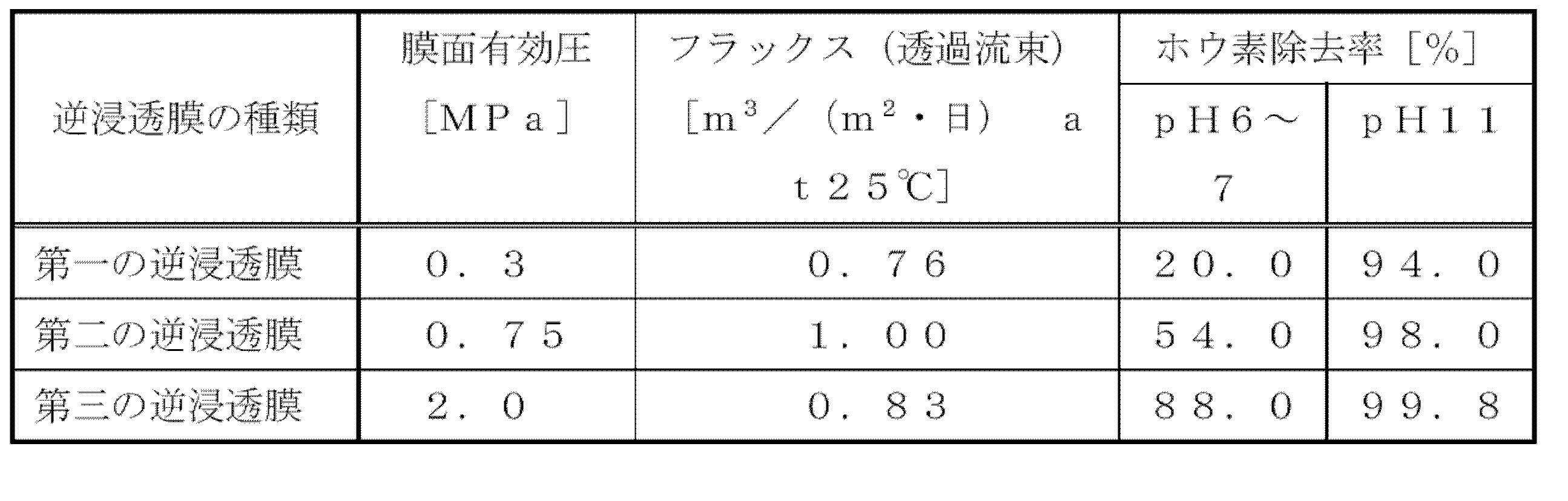
図1に示す多段逆浸透膜処理システムを用いた純水製造装置において、純水にホウ素を500μg/L添加した被処理水W0を所定の単位水量(フラックス=1.0m3/(m2・日)at25℃)となるように供給するとともに、第一の逆浸透膜6の前段でpHを11に調整して純水製造装置1を運転した。この際のイオン交換装置7の前段(最後段の逆浸透膜の出口)のホウ素濃度の測定結果に基づきウ素除去率を算出した。結果をフラックス、同等のフラックスを得るのに必要な膜面有効圧力とともに表2にあわせて示す。
図2に示す多段逆浸透膜処理システムを用いた純水製造装置において、純水にホウ素を500μg/L添加した被処理水W0を所定の単位水量(フラックス=1.0m3/(m2・日)at25℃)となるように供給するするとともに、第一の逆浸透膜6Bの前段でpHを11に調整して純水製造装置1を運転した。この際のイオン交換装置7の前段(最後段の逆浸透膜出口)のホウ素濃度の測定結果に基づきウ素除去率を算出した。結果をフラックス、同等のフラックスを得るのに必要な膜面有効圧力とともに表2にあわせて示す。
図3に示す多段逆浸透膜処理システムを用いた純水製造装置において、純水にホウ素を500μg/L添加した被処理水W0を所定の単位水量(フラックス=1.0m3/(m2・日)at25℃)となるように供給するするとともに、第一の逆浸透膜6Dの前段でpHを11に調整して純水製造装置1を運転した。この際のイオン交換装置7の前段(最後段の逆浸透膜出口)のホウ素濃度の測定結果に基づきウ素除去率を算出した。結果をフラックス、同等のフラックスを得るのに必要な膜面有効圧力とともに表2にあわせて示す。
図4に示す多段逆浸透膜処理システムを用いた純水製造装置において、純水にホウ素を500μg/L添加した被処理水W0(pH6~7)を所定の単位水量(フラックス=1.0m3/(m2・日)at25℃)となるように供給して純水製造装置1を運転した。この際のイオン交換装置7の前段(最後段の逆浸透膜出口)のホウ素濃度の測定結果に基づきウ素除去率を算出した。結果をフラックス、同等のフラックスを得るのに必要な膜面有効圧力とともに表2にあわせて示す。
図5に示す多段逆浸透膜処理システムを用いた純水製造装置において、純水にホウ素を500μg/L添加した被処理水W0(pH6~7)を所定の単位水量(フラックス=1.0m3/(m2・日)at25℃)となるように供給して純水製造装置1を運転した。この際のイオン交換装置7の前段(最後段の逆浸透膜出口)のホウ素濃度の測定結果に基づきウ素除去率を算出した。結果をフラックス、同等のフラックスを得るのに必要な膜面有効圧力とともに表2にあわせて示す。
図6に示す多段逆浸透膜処理システムを用いた純水製造装置において、純水にホウ素を500μg/L添加した被処理水W0を所定の単位水量(フラックス=1.0m3/(m2・日)at25℃)となるように供給するするとともに、第二の逆浸透膜12Dの前段でpHを11に調整して純水製造装置1を運転した。この際のイオン交換装置7の前段(最後段の逆浸透膜出口)のホウ素濃度の測定結果に基づきウ素除去率を算出した。結果をフラックス、同等のフラックスを得るのに必要な膜面有効圧力とともに表2にあわせて示す。
運転エネルギー削減率=(1.5-1.2)/1.5×100=20(%)
2 貯槽
3 通水配管
4 送液ポンプ
5 第二の逆浸透膜
6,6A,6B,6C,6D,6E 第一の逆浸透膜
7 イオン交換装置
8 NaOH水溶液添加手段(アルカリ添加機構)
W0 被処理水
W1 一次処理水
W2 二次処理水
W3 三次処理水
W 純水
Claims (4)
- 逆浸透膜を2段以上直列に配置した多段逆浸透膜処理システムであって、前記2段以上の逆浸透膜の少なくともいずれかは、膜面有効圧力1MPa(水温25℃、純水(RO透過水))あたりの透過流束2.0m3/(m2・日)以上の逆浸透膜(以下、第一の逆浸透膜とする)であり、前記第一の逆浸透膜の被処理水のpHをアルカリ側に調整して処理する多段逆浸透膜処理システム。
- 前記第一の逆浸透膜を2段直列に配置し、該第一の逆浸透膜のいずれかの被処理水のpHをアルカリ側に調整して処理する、請求項1に記載の多段逆浸透膜処理システム。
- 膜面有効圧力1MPa(水温25℃、純水(RO透過水))あたりの透過流束0.8m3/(m2・日)以上の逆浸透膜(以下、第二の逆浸透膜とする)と、前記第一の逆浸透膜とを直列に配置し、該第一の逆浸透膜の被処理水のpHをアルカリ側に調整して処理する、請求項1に記載の多段逆浸透膜処理システム。
- 前記多段逆浸透膜処理システムの被処理水の水質がホウ素濃度1~500μg/L及び/又はシリカ濃度1~50mg/Lである、請求項1~3のいずれか1項に記載の多段逆浸透膜処理システム。
Priority Applications (3)
| Application Number | Priority Date | Filing Date | Title |
|---|---|---|---|
| CN202280074352.4A CN118201881A (zh) | 2021-11-09 | 2022-09-13 | 多级反渗透膜处理系统 |
| EP22892403.1A EP4431465A4 (en) | 2021-11-09 | 2022-09-13 | MULTI-STAGE REVERSE OSMOSIS MEMBRANE TREATMENT SYSTEM |
| KR1020247010728A KR20240108373A (ko) | 2021-11-09 | 2022-09-13 | 다단 역침투막 처리 시스템 |
Applications Claiming Priority (2)
| Application Number | Priority Date | Filing Date | Title |
|---|---|---|---|
| JP2021182541A JP7363876B2 (ja) | 2021-11-09 | 2021-11-09 | 多段逆浸透膜処理システム |
| JP2021-182541 | 2021-11-09 |
Publications (1)
| Publication Number | Publication Date |
|---|---|
| WO2023084902A1 true WO2023084902A1 (ja) | 2023-05-19 |
Family
ID=86331442
Family Applications (1)
| Application Number | Title | Priority Date | Filing Date |
|---|---|---|---|
| PCT/JP2022/034165 Ceased WO2023084902A1 (ja) | 2021-11-09 | 2022-09-13 | 多段逆浸透膜処理システム |
Country Status (5)
| Country | Link |
|---|---|
| EP (1) | EP4431465A4 (ja) |
| JP (1) | JP7363876B2 (ja) |
| KR (1) | KR20240108373A (ja) |
| CN (1) | CN118201881A (ja) |
| WO (1) | WO2023084902A1 (ja) |
Cited By (1)
| Publication number | Priority date | Publication date | Assignee | Title |
|---|---|---|---|---|
| WO2026038403A1 (ja) * | 2024-08-14 | 2026-02-19 | 栗田工業株式会社 | 多段逆浸透膜処理システム |
Citations (4)
| Publication number | Priority date | Publication date | Assignee | Title |
|---|---|---|---|---|
| JPH09290275A (ja) * | 1996-02-29 | 1997-11-11 | Toray Ind Inc | 水中のほう素の除去装置およびその方法 |
| JP2001145879A (ja) * | 1999-11-19 | 2001-05-29 | Kurita Water Ind Ltd | 純水製造装置 |
| JP2018079451A (ja) | 2016-11-18 | 2018-05-24 | オルガノ株式会社 | 逆浸透膜処理システムおよび逆浸透膜処理方法 |
| WO2020184045A1 (ja) * | 2019-03-13 | 2020-09-17 | オルガノ株式会社 | ホウ素除去装置及びホウ素除去方法、並びに、純水製造装置及び純水の製造方法 |
Family Cites Families (7)
| Publication number | Priority date | Publication date | Assignee | Title |
|---|---|---|---|---|
| US6379518B1 (en) * | 1999-08-11 | 2002-04-30 | Kurita Water Industries Ltd. | Electrodeionization apparatus and pure water producing apparatus |
| US7540292B2 (en) * | 2003-02-25 | 2009-06-02 | Kurita Water Industries Ltd. | Detergent for washing a selectively permeable membrane and method of washing |
| BRPI0917617B8 (pt) * | 2008-12-09 | 2018-09-25 | Toray Industries | método para produzir açúcar líquido e método para produzir um produto químico |
| JP5569784B2 (ja) * | 2010-03-16 | 2014-08-13 | 三浦工業株式会社 | 純水製造システム |
| JP6065066B2 (ja) * | 2015-06-30 | 2017-01-25 | 栗田工業株式会社 | ボイラ用水処理装置及びボイラの運転方法 |
| JP7454330B2 (ja) * | 2018-06-20 | 2024-03-22 | オルガノ株式会社 | 被処理水中のホウ素除去方法、ホウ素除去システム、超純水製造システム及びホウ素濃度の測定方法 |
| JP7200014B2 (ja) * | 2019-03-13 | 2023-01-06 | オルガノ株式会社 | 純水製造装置および純水の製造方法 |
-
2021
- 2021-11-09 JP JP2021182541A patent/JP7363876B2/ja active Active
-
2022
- 2022-09-13 CN CN202280074352.4A patent/CN118201881A/zh active Pending
- 2022-09-13 KR KR1020247010728A patent/KR20240108373A/ko active Pending
- 2022-09-13 WO PCT/JP2022/034165 patent/WO2023084902A1/ja not_active Ceased
- 2022-09-13 EP EP22892403.1A patent/EP4431465A4/en active Pending
Patent Citations (4)
| Publication number | Priority date | Publication date | Assignee | Title |
|---|---|---|---|---|
| JPH09290275A (ja) * | 1996-02-29 | 1997-11-11 | Toray Ind Inc | 水中のほう素の除去装置およびその方法 |
| JP2001145879A (ja) * | 1999-11-19 | 2001-05-29 | Kurita Water Ind Ltd | 純水製造装置 |
| JP2018079451A (ja) | 2016-11-18 | 2018-05-24 | オルガノ株式会社 | 逆浸透膜処理システムおよび逆浸透膜処理方法 |
| WO2020184045A1 (ja) * | 2019-03-13 | 2020-09-17 | オルガノ株式会社 | ホウ素除去装置及びホウ素除去方法、並びに、純水製造装置及び純水の製造方法 |
Non-Patent Citations (1)
| Title |
|---|
| See also references of EP4431465A4 |
Cited By (2)
| Publication number | Priority date | Publication date | Assignee | Title |
|---|---|---|---|---|
| WO2026038403A1 (ja) * | 2024-08-14 | 2026-02-19 | 栗田工業株式会社 | 多段逆浸透膜処理システム |
| JP2026032608A (ja) * | 2024-08-14 | 2026-02-27 | 栗田工業株式会社 | 多段逆浸透膜処理システム |
Also Published As
| Publication number | Publication date |
|---|---|
| CN118201881A (zh) | 2024-06-14 |
| EP4431465A4 (en) | 2025-11-12 |
| JP2023070396A (ja) | 2023-05-19 |
| JP7363876B2 (ja) | 2023-10-18 |
| EP4431465A1 (en) | 2024-09-18 |
| KR20240108373A (ko) | 2024-07-09 |
Similar Documents
| Publication | Publication Date | Title |
|---|---|---|
| CN101827792B (zh) | 纯水制造装置及纯水制造方法 | |
| JP4798644B2 (ja) | 逆浸透膜を用いる脱塩方法 | |
| EP1363856B1 (en) | Method of boron removal in presence of magnesium ions | |
| TWI826657B (zh) | 純水製造裝置及純水之製造方法 | |
| TWI738493B (zh) | 水處理系統及水處理方法 | |
| KR20160135325A (ko) | 순수 제조 장치 및 순수 제조 방법 | |
| CN110291045A (zh) | 超纯水制造方法及超纯水制造系统 | |
| JP2017140550A (ja) | 純水製造装置、純水製造方法及び超純水製造装置 | |
| JP2012245439A (ja) | 超純水製造装置 | |
| CN115916708A (zh) | 除盐装置的运转方法 | |
| JP2014213306A (ja) | 純水製造装置、純水およびろ過水製造装置、純水製造方法、ならびに純水およびろ過水製造方法 | |
| JP7363876B2 (ja) | 多段逆浸透膜処理システム | |
| JP5569784B2 (ja) | 純水製造システム | |
| JP4119040B2 (ja) | 機能水製造方法及び装置 | |
| JP4432583B2 (ja) | 超純水製造装置 | |
| JP2011189302A (ja) | 純水製造システム | |
| JP3912067B2 (ja) | 一次純水製造装置 | |
| WO2026038403A1 (ja) | 多段逆浸透膜処理システム | |
| CN110550789B (zh) | 一种半导体纯水处理系统 | |
| JP4618073B2 (ja) | 高toc含有cmp排水からの水回収方法及び水回収装置 | |
| WO2014010075A1 (ja) | 超純水製造装置 | |
| JP3227765B2 (ja) | 膜分離装置 | |
| JP2023128657A (ja) | 水処理システム及び水処理方法 | |
| WO2025225161A1 (ja) | 逆浸透膜装置の運転方法 | |
| TW202311174A (zh) | 超純水製造方法及裝置 |
Legal Events
| Date | Code | Title | Description |
|---|---|---|---|
| 121 | Ep: the epo has been informed by wipo that ep was designated in this application |
Ref document number: 22892403 Country of ref document: EP Kind code of ref document: A1 |
|
| WWE | Wipo information: entry into national phase |
Ref document number: 202280074352.4 Country of ref document: CN |
|
| WWE | Wipo information: entry into national phase |
Ref document number: 18708595 Country of ref document: US |
|
| WWE | Wipo information: entry into national phase |
Ref document number: 2022892403 Country of ref document: EP |
|
| NENP | Non-entry into the national phase |
Ref country code: DE |
|
| ENP | Entry into the national phase |
Ref document number: 2022892403 Country of ref document: EP Effective date: 20240610 |
|
| WWE | Wipo information: entry into national phase |
Ref document number: 11202403238T Country of ref document: SG |