WO2023084992A1 - 作業機械 - Google Patents
作業機械 Download PDFInfo
- Publication number
- WO2023084992A1 WO2023084992A1 PCT/JP2022/038398 JP2022038398W WO2023084992A1 WO 2023084992 A1 WO2023084992 A1 WO 2023084992A1 JP 2022038398 W JP2022038398 W JP 2022038398W WO 2023084992 A1 WO2023084992 A1 WO 2023084992A1
- Authority
- WO
- WIPO (PCT)
- Prior art keywords
- controller
- drive source
- lock
- switch
- lever
- Prior art date
- Legal status (The legal status is an assumption and is not a legal conclusion. Google has not performed a legal analysis and makes no representation as to the accuracy of the status listed.)
- Ceased
Links
Images



Classifications
-
- E—FIXED CONSTRUCTIONS
- E02—HYDRAULIC ENGINEERING; FOUNDATIONS; SOIL SHIFTING
- E02F—DREDGING; SOIL-SHIFTING
- E02F9/00—Component parts of dredgers or soil-shifting machines, not restricted to one of the kinds covered by groups E02F3/00 - E02F7/00
- E02F9/24—Safety devices, e.g. for preventing overload
-
- E—FIXED CONSTRUCTIONS
- E02—HYDRAULIC ENGINEERING; FOUNDATIONS; SOIL SHIFTING
- E02F—DREDGING; SOIL-SHIFTING
- E02F9/00—Component parts of dredgers or soil-shifting machines, not restricted to one of the kinds covered by groups E02F3/00 - E02F7/00
- E02F9/20—Drives; Control devices
- E02F9/2004—Control mechanisms, e.g. control levers
-
- E—FIXED CONSTRUCTIONS
- E02—HYDRAULIC ENGINEERING; FOUNDATIONS; SOIL SHIFTING
- E02F—DREDGING; SOIL-SHIFTING
- E02F9/00—Component parts of dredgers or soil-shifting machines, not restricted to one of the kinds covered by groups E02F3/00 - E02F7/00
- E02F9/20—Drives; Control devices
- E02F9/2004—Control mechanisms, e.g. control levers
- E02F9/2012—Setting the functions of the control levers, e.g. changing assigned functions among operations levers, setting functions dependent on the operator or seat orientation
-
- E—FIXED CONSTRUCTIONS
- E02—HYDRAULIC ENGINEERING; FOUNDATIONS; SOIL SHIFTING
- E02F—DREDGING; SOIL-SHIFTING
- E02F9/00—Component parts of dredgers or soil-shifting machines, not restricted to one of the kinds covered by groups E02F3/00 - E02F7/00
- E02F9/20—Drives; Control devices
- E02F9/2058—Electric or electro-mechanical or mechanical control devices of vehicle sub-units
- E02F9/2062—Control of propulsion units
-
- E—FIXED CONSTRUCTIONS
- E02—HYDRAULIC ENGINEERING; FOUNDATIONS; SOIL SHIFTING
- E02F—DREDGING; SOIL-SHIFTING
- E02F9/00—Component parts of dredgers or soil-shifting machines, not restricted to one of the kinds covered by groups E02F3/00 - E02F7/00
- E02F9/20—Drives; Control devices
- E02F9/2058—Electric or electro-mechanical or mechanical control devices of vehicle sub-units
- E02F9/2062—Control of propulsion units
- E02F9/207—Control of propulsion units of the type electric propulsion units, e.g. electric motors or generators
-
- E—FIXED CONSTRUCTIONS
- E02—HYDRAULIC ENGINEERING; FOUNDATIONS; SOIL SHIFTING
- E02F—DREDGING; SOIL-SHIFTING
- E02F9/00—Component parts of dredgers or soil-shifting machines, not restricted to one of the kinds covered by groups E02F3/00 - E02F7/00
- E02F9/20—Drives; Control devices
- E02F9/22—Hydraulic or pneumatic drives
- E02F9/2246—Control of prime movers, e.g. depending on the hydraulic load of work tools
-
- E—FIXED CONSTRUCTIONS
- E02—HYDRAULIC ENGINEERING; FOUNDATIONS; SOIL SHIFTING
- E02F—DREDGING; SOIL-SHIFTING
- E02F9/00—Component parts of dredgers or soil-shifting machines, not restricted to one of the kinds covered by groups E02F3/00 - E02F7/00
- E02F9/20—Drives; Control devices
- E02F9/22—Hydraulic or pneumatic drives
- E02F9/2278—Hydraulic circuits
- E02F9/2296—Systems with a variable displacement pump
Definitions
- the present invention relates to a working machine that includes a drive source and a controller that controls starting and stopping of the drive source.
- Patent Document 1 discloses a hydraulic working machine capable of locking the operation of an actuator.
- the engine is started by operating the start switch. After that, by rotating the lock lever to the unlocked position (unlocked position), the lock valve is turned on and the pilot pressure is allowed to be supplied to the switching valve.
- the switching valve is in the OFF state when the isolation switch is not operated, thereby keeping the actuator stopped.
- the pilot valve opens to allow the pilot pressure to be supplied to the actuator. This causes the actuator to operate.
- Patent Document 2 discloses a construction machine capable of reducing battery power consumption.
- the main control unit and the fan control unit determine whether the lock lever is in the locked position or the unlocked position based on whether or not a signal is input from the lock switch.
- the fan control unit drives the fan electric motor to rotate the cooling fan.
- the main electric motor is driven during the initial startup of the hydraulic excavator and while the operator is operating any operating device.
- An object of the present invention is to provide a work machine capable of preventing machine operation unintended by the operator and reducing energy consumption.
- a work machine includes a drive source, a controller, a controller switch, an operation lever, a lock operation member, and a drive source switch.
- the controller controls starting and stopping of the drive source.
- the controller switch allows an ON operation for activating the controller and an OFF operation for stopping the controller to be given to the controller switch.
- the operation lever allows a lever operation for moving an operation target to be given to the operation lever.
- the lock operation member allows a lock operation for disabling the lever operation and an unlock operation for enabling the lever operation to be applied to the lock operation member.
- the drive source switch allows a start operation for starting the drive source and a stop operation for stopping the drive source to be given to the drive source switch.
- the controller receives the unlocking operation from the lock operation member and the starting operation from the drive source switch in a state in which the controller switch is turned on and the controller is activated.
- the drive source is started when it is determined that the lock operation member is unlocked or the drive source switch is not started. configured to hold.
- FIG. 1 is a diagram showing a control system for an electric hydraulic excavator according to an embodiment of the present invention
- FIG. Fig. 2 is a plan view showing the inside of the operator's cab of the electric hydraulic excavator; It is a perspective view which shows the right front part in the said cab. It is a perspective view which shows the left front part of the said cab.
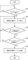
- 4 is a flow chart showing a control operation performed by a controller of the electric hydraulic excavator for starting an electric motor. 4 is a flow chart showing a control operation of restarting the stopped electric motor by the controller;
- FIG. 11 is a diagram showing a control system for a hydraulic excavator according to a modified example;
- FIG. 1 shows a control system mounted on an electric hydraulic excavator 1, which is a work machine according to the embodiment.
- the electric hydraulic excavator 1 includes a controller 2, an electric motor 3, a key switch 4, a lock lever 5, a grip switch 6, a left operating lever 60L, a right operating lever 60R, a battery 31, a hydraulic pump 33, and a plurality of hydraulic actuators (not shown). , a plurality of control valves 37 and a plurality of solenoid valves 35 .
- the controller 2 controls the operation of the electric hydraulic excavator 1 , and the control includes starting and stopping of the electric motor 3 .
- the electric motor 3 is a drive source for the electric hydraulic excavator 1 .
- the electric motor 3 is driven by electric power supplied from the battery 31 to drive the hydraulic pump 33 and a pilot pump (not shown).
- the hydraulic pump 33 is a variable displacement hydraulic pump, and is driven by the electric motor 3 to discharge hydraulic oil.
- the hydraulic pump 33 includes a pump body having a variable pump capacity and a regulator that changes the pump capacity. The regulator changes the pump displacement according to a pump displacement command input from the controller 2 .
- the electric hydraulic excavator 1 further includes an operator's cab 11 shown in FIG.
- the left and right operating levers 60L and 60R are arranged in front of consoles arranged on both left and right sides of the driver's seat 13, respectively.
- Each of the operating levers 60L and 60R constitutes an electric lever device together with a lever sensor (not shown) and others.
- the lever sensor converts an operation amount (inclination angle of the operation levers 60L, 60R), which is the magnitude of operation input to the operation levers 60L, 60R, into an operation signal, which is an electric signal, and inputs the signal to the controller 2. do.
- the plurality of hydraulic actuators operate to respectively move the plurality of movable parts included in the electric hydraulic excavator 1 .
- the plurality of hydraulic actuators are operated by hydraulic fluid supplied from the hydraulic pump 33 via the plurality of control valves 37, respectively.
- the plurality of hydraulic actuators are objects to be operated by the lever operations applied to the right and left operating levers 60L and 60R.
- the plurality of control valves 37 are interposed between the hydraulic pump 33 and the plurality of hydraulic actuators to enable the controller 2 to control the operations of the plurality of hydraulic actuators.
- Each of the plurality of control valves 37 is configured by a pilot-operated hydraulic switching valve, and a flow rate corresponding to the pilot pressure input to the control valve 37 is supplied from the hydraulic pump 33 to the control valve among the plurality of hydraulic actuators.
- the valve 37 is opened to allow hydraulic fluid to be supplied to the hydraulic actuator corresponding to the valve 37 .
- the plurality of solenoid valves 35 are interposed between the pilot pump (not shown) and the plurality of control valves 37 so as to change the pilot pressure input from the pilot pump to each of the plurality of control valves 37. Open the valve.
- each of the plurality of solenoid valves 35 reduces the pilot primary pressure, which is the discharge pressure of the pilot pump, by a degree corresponding to the drive signal input from the controller 2, and reduces the pilot pressure corresponding to the command signal.
- a pressure (pilot secondary pressure) is generated, and the pilot pressure is input to the control valve 37 among the plurality of control valves 37 to which the electromagnetic valve 35 is connected.
- the controller 2 generates, as the drive signal, a signal that causes the plurality of hydraulic actuators to operate corresponding to the lever operation based on the operation signal input from the electric lever device, and the corresponding solenoid valve Enter 35.
- the key switch 4 is a physical key that can be rotated. In the arrangement shown in FIGS. It is located behind the operating lever 60R. The key switch 4 is switched from the OFF position to the ON position or from the ON position to the OFF position by the rotational operation given by the operator.
- the key switch 4 is a controller switch operated to turn the controller 2 on and off. Specifically, the key switch 4 is configured to allow a start command signal to be input to the controller 2 by an operation (ON operation) that rotates the key switch 4 from the OFF position to the ON position. The activation command signal activates (energizes) a plurality of electrical components including the controller 2 . Conversely, the key switch 4 is configured to allow a stop command signal to be input to the controller 2 by an operation (OFF operation) that rotates the key switch 4 from the ON position to the OFF position. The stop command signal stops electrical components including the controller 2 (suspends the energization).
- the key switch 4 can be operated to turn on (energize) the electrical equipment including the controller 2 and to turn off the electrical equipment (suspend the current supply). It functions as a switch that allows input, that is, the controller switch.
- the "controller switch” according to the present invention may alternatively be a push-type switch in which the ON operation and the OFF operation given to the controller switch are respectively pressing operations.
- the lock lever 5 is a safety lever for preventing the actuator from operating against the operator's intention in the non-operating state.
- the lock lever 5 is provided on the left side of the driver's seat 13 and in front of the left operation lever 60L.
- the lock lever 5 is a lock operation member that can be moved between an upper lock position and a lower unlock position by manual operation by an operator.
- the manual operation includes a pull-up operation of pulling up the lock lever 5 to move it to the lock position, and a push-down operation of pushing down the lock lever 5 to move it to the unlocked position.
- the lock lever 5 is configured to allow a lock command signal to be input to the controller 2 when it is moved from the unlocked position to the locked position by the pulling operation.
- the controller 2 stops the input of the drive signal to the electromagnetic valve 35 in response to the input of the lock command signal, thereby closing the electromagnetic valve 35 and stopping the input of the pilot pressure to the control valve 37. Force stop.
- the controller 2 may be configured to cut off the supply of the pilot primary pressure from the pilot pump to the solenoid valve 35 upon receipt of the lock command signal. In either case, the lever operations applied to the operating levers 60L and 60R are invalidated. That is, the input of the drive signal from the controller 2 to the electromagnetic valve 35 is forcibly stopped regardless of the lever operation applied to the operating levers 60L and 60R.
- the lock lever 5 stops the input of the lock command signal to the controller 2 when it is moved from the lock position to the unlock position by the pressing operation, and the electromagnetic wave is released from the controller 2. It is configured to allow the input of said drive signal to the valve 35 .
- the electromagnetic valve 35 opens to allow the pilot pressure to be supplied to the control valve 37 . That is, the lever operations applied to the operating levers 60L and 60R are validated, and the input of drive signals from the controller 2 to the control valve 37 corresponding to the lever operations is permitted.
- the lock lever 5 is configured such that a lock operation for disabling the lever operation given to the operation levers 60L and 60R and an unlock operation for validating the lever operation are performed by the lock lever. 5 is allowed to be entered. That is, the lock lever 5 functions as a lock operation member.
- the grip switch 6 is a switch for switching between starting and stopping the electric motor 3, which is a drive source, that is, a drive source switch.
- the grip switch 6 is provided at the upper end of the right operating lever 60R and can be pressed by an operator. That is, the grip switch 6 is a push-type switch in this embodiment.
- the electric motor 3 is alternately started and stopped. That is, the pressing operation applied to the grip switch 6 while the electric motor 3 is stopped corresponds to the starting operation for starting the electric motor 3, and the grip switch 6 to which the starting operation is applied Input of the start command signal to the controller 2 is permitted.
- the controller 2 starts the electric motor 3 when the start command signal is input.
- the pressing operation applied to the grip switch 6 while the electric motor 3 is being driven corresponds to a stop operation for stopping the electric motor 3, and the grip switch 6 subjected to the stop operation Input of a stop command signal to the controller 2 is permitted.
- the controller 2 forcibly stops the electric motor 3 when the stop command signal is input.
- the grip switch 6 functions as the drive source switch according to the present invention.
- FIG. 5 the control operation performed by the controller 2 will be described with reference to the flow charts shown in FIGS. 5 and 6.
- FIG. 5 shows the operation performed to start the electric motor 3, which is the driving source.
- a start command signal is input to the controller 2 to start the electrical equipment including the controller 2. That is, Power is supplied (step S11).
- the controller 2 determines whether or not the lock lever 5 is at the unlocked position. In other words, the controller 2 determines whether or not the unlocking operation for validating the lever operations applied to the operating levers 60L and 60R is applied to the lock lever 5 (step S12).
- step S12 When it is determined that the lock release operation has been applied to the lock lever 5 (YES in step S12), the controller 2 performs the processing of step S13. That is, the controller 2 determines whether or not the grip switch 6 has been operated to start, that is, whether or not the grip switch 6 has been pressed while the electric motor 3 is stopped.
- step S13 When it is determined that the starting operation has been given to the grip switch 6 (YES in step S13), the controller 2 starts the electric motor 3, which is the driving source (step S14). As a result, the hydraulic pump 33 is driven, and the regulator of the hydraulic pump 33 minimizes the tilting angle of the hydraulic pump 33, that is, in a state in which the pump displacement of the hydraulic pump 33 is minimum. 33 discharges hydraulic fluid at a minimum flow rate.
- the pilot pump is also driven to supply the pilot primary pressure to each of the plurality of electromagnetic valves 35 .
- the controller 2 is a control valve connected from the electromagnetic valve 35 to the electromagnetic valve 35 by inputting a drive signal to the electromagnetic valve 35 corresponding to the lever operation among the plurality of electromagnetic valves 35 to open the electromagnetic valve 35; 37 is allowed to be supplied with pilot pressure (pilot secondary pressure).
- pilot pressure pilot secondary pressure
- the control valve 37 allows hydraulic fluid to be supplied from the hydraulic pump 33 to the hydraulic actuator (operation target) corresponding to the control valve 37 at a flow rate corresponding to the pilot pressure.
- the controller 2 inputs a pump displacement command to the hydraulic pump 33 to increase the pump displacement of the hydraulic pump 33, whereby the hydraulic actuator (operating object) is driven more preferably.
- FIG. 6 shows an operation for restarting the electric motor 3 that has been stopped due to the lock operation applied to the lock lever 5.
- step S31 the controller 2 determines whether or not the lock lever 5 has been moved from the unlocked position to the locked position while the electric motor 3 is being driven. In other words, the controller 2 determines whether or not the lock lever 5 has been subjected to the lock operation for nullifying the lever operations applied to the left and right operation levers 60L and 60R.
- step S31 When it is determined that the locking operation has been applied to the lock lever 5 (YES in step S31), the controller 2 forcibly stops the electric motor 3, which is the drive source (step S32).
- step S33 the controller 2 determines whether the lock lever 5 has been returned from the lock position to the unlock position. 5 is given again (step S33). The controller 2 keeps the electric motor 3 forcedly stopped until it is determined that the lock release operation has been given to the lock lever 5 (NO in step S33).
- step S33 When it is determined that the lock release operation has been applied to the lock lever 5 (YES in step S33), the controller 2 pushes the grip switch 6 while the electric motor 3 is stopped as described above. It is determined whether or not a lowering operation has been given, that is, whether or not a starting operation has been given to the grip switch 6 (step S34). When it is determined that the starting operation has been given to the grip switch 6 (YES in step S34), the controller 2 restarts the electric motor 3, which is the drive source.
- the controller 2 is operated when the key switch 4 is turned off while the electric motor 3 is being driven, and when the grip switch 6 is pressed or stopped.
- the electric motor 3 is also forcibly stopped when it is determined that the operation has been given. That is, when it is determined that at least one of the turning off operation to the key switch 4 and the stopping operation to the grip switch 6 is performed while the electric motor 3 is being driven, the controller 2 The electric motor 3, which is the driving source, is stopped.
- the controller 2 keeps the drive source in the state where the electric motor 3 is stopped, even if the lock release operation is given to the lock lever 5, unless the grip switch 6 is given the start operation.
- the starting of the electric motor 3 is suspended. This means that the operator may unintentionally touch the operating lever (either the left or right operating lever 60L or 60R in this embodiment) unconsciously while the unlocking operation is being performed. Prevent movement from occurring.
- controller 2 unless all of the ON operation to the key switch 4, the unlock operation to the lock lever 5, and the starting operation to the grip switch 6 are permitted. It is possible to suspend the starting of the electric motor 3, which is the drive source, thereby reducing the energy consumption of the electric motor 3.
- the controller 2 applies the OFF operation to the key switch 4, the lock operation to the lock lever 5, and the grip switch 6 while the electric motor 3 is being driven.
- the electric motor 3, which is the drive source, is stopped when it is determined that any one of the stop operations has been applied to the motor. This makes it possible for the operator to stop the electric motor 3 quickly when he stops working. This also makes it possible to suppress energy consumption by the electric motor 3 .
- the controller 2 is configured such that even if the unlocking operation is applied to the lock lever 5 in a state in which the electric motor 3 is stopped in accordance with the lock operation applied to the lock lever 5 , the lock release operation is applied. Unless the grip switch 6 is given the starting operation, the restart of the electric motor 3 is put on hold. This prevents the machine from performing an operation unintended by the operator immediately after the unlocking operation is given to the lock lever 5, thereby ensuring high safety.
- the electric hydraulic excavator 1 shown in FIG. 1 includes the electric motor 3 as a drive source, but the present invention is also applied to a hydraulic excavator 10 including an engine 8 as a drive source, as shown in FIG. It is possible to
- This hydraulic excavator 10 includes a remote control valve 70 connected to the operating lever 60 in addition to the operating lever 60 .
- the remote control valve 70 is interposed between a pilot pump (not shown) and the control valve 37 . , the valve is opened in conjunction with the operation of the lever.
- the controller 2 controls the upstream of the remote control valve 70, for example.
- the supply of the pilot primary pressure to the remote control valve 70 is forcibly cut off by closing the lock valve (not shown) arranged on the side, thereby disabling the supply of the pilot pressure to the control valve 37.
- the lever operation given to the operating lever 60 is invalidated.
- the lock lever 5 when the operator gives an unlocking operation to the lock lever 5 (for example, when the lock lever 5 is pushed down to move the lock lever 5 from the lock position to the unlock position), the lock lever 5 is, for example, locked.
- the supply of the pilot primary pressure to the remote control valve 70 is permitted, thereby enabling the supply of the pilot pressure to the control valve 37 and enabling the lever operation by the operation levers 60L and 60R. do.
- the control for starting the engine 8 performed by the controller 2 is the same as the control for starting the electric motor 3 according to the embodiment, that is, the control shown in the flowchart of FIG. Specifically, the controller 2 according to this modification starts the engine 8, which is a driving source replacing the electric motor 3, in step S14 of FIG.
- the working machine includes a drive source, a controller, a controller switch, an operation lever, a lock operation member, and a drive source switch.
- the controller controls starting and stopping of the drive source.
- the controller switch allows an ON operation for activating the controller and an OFF operation for stopping the controller to be given to the controller switch.
- the operation lever allows a lever operation for moving an operation target to be given to the operation lever.
- the lock operation member allows a lock operation for disabling the lever operation and an unlock operation for enabling the lever operation to be applied to the lock operation member.
- the drive source switch allows a start operation for starting the drive source and a stop operation for stopping the drive source to be given to the drive source switch.
- the controller receives the unlocking operation from the lock operation member and the starting operation from the drive source switch in a state in which the controller switch is turned on and the controller is activated.
- the drive source is started when it is determined that the unlocking operation is applied to the lock operation member or the start operation is not applied to the drive source switch. is configured to hold
- the controller suspends starting of the driving source when the driving source switch is not subjected to the starting operation even if the unlocking operation is applied to the lock operation member. This prevents an unintended mechanical operation of the operator who performs the unlocking operation due to unintentional contact with the operating lever. Further, the drive source is operated only when all of the application of the ON operation to the controller switch, the application of the unlock operation to the lock operation member, and the application of the start operation to the drive source switch are performed. will not start, which allows a reduction in energy consumption.
- the controller applies the off operation to the controller switch, the lock operation to the lock operation member, and the stop operation to the drive source switch while the drive source is being driven. It is preferable that the driving source is stopped when it is determined that the above is performed. This makes it possible for the operator to quickly stop the drive source when stopping work. This also makes it possible to suppress energy consumption by the drive source.
- the controller determines that the lock release operation is applied to the lock operation member.
- Starting of the drive source is suspended until it is determined that the switch has been given the starting operation, and it is determined that the unlocking operation has been given to the lock operation member and the starting operation has been given to the drive source switch. It is preferable that the driving source is started when the power supply is turned on. This prevents the machine from performing an operation unintended by the operator immediately after the unlocking operation is given to the lock operation member, thereby ensuring high safety.
Landscapes
- Engineering & Computer Science (AREA)
- Mining & Mineral Resources (AREA)
- Civil Engineering (AREA)
- General Engineering & Computer Science (AREA)
- Structural Engineering (AREA)
- Operation Control Of Excavators (AREA)
- Component Parts Of Construction Machinery (AREA)
Abstract
Description
Claims (3)
- 作業機械であって、
駆動源と、
前記駆動源の始動及び停止を制御するコントローラと、
コントローラスイッチであって、前記コントローラを起動させるためのオン操作と、前記コントローラを停止させるためのオフ操作と、が当該コントローラスイッチに与えられることを許容するコントローラスイッチと、
操作レバーであって、操作対象を動かすためのレバー操作が当該操作レバーに与えられることを許容する操作レバーと、
ロック操作部材であって、前記レバー操作を無効にするためのロック操作と、前記レバー操作を有効にするためのロック解除操作と、が当該ロック操作部材に与えられることを許容するロック操作部材と、
駆動源スイッチであって、前記駆動源を始動させるための始動操作と、前記駆動源を停止させるための停止操作と、が当該駆動源スイッチに与えられることを許容する駆動源スイッチと、を備え、
前記コントローラは、前記コントローラスイッチに前記オン操作が与えられて当該コントローラが起動している状態において、前記ロック操作部材に前記ロック解除操作が与えられ、かつ、前記駆動源スイッチに前記始動操作が与えられたと判断したときに前記駆動源を始動させ、前記ロック操作部材に前記ロック解除操作が与えられていないときまたは前記駆動源スイッチに前記始動操作が与えられていないときは前記駆動源の始動を保留するように構成されている、作業機械。 - 請求項1に記載の作業機械であって、前記コントローラは、前記駆動源の駆動中において、前記コントローラスイッチへの前記オフ操作の付与、前記ロック操作部材への前記ロック操作の付与、及び前記駆動源スイッチへの前記停止操作の付与、のいずれかが行われたと判断したときに前記駆動源を停止させるように構成されている、作業機械。
- 請求項2に記載の作業機械であって、前記コントローラは、前記ロック操作部材に前記ロック操作が与えられたと判断して前記駆動源を停止させた後、前記ロック操作部材に前記ロック解除操作が与えられたと判断しても前記駆動源スイッチに前記始動操作が与えられたと判断するまでは前記駆動源の始動を保留し、前記ロック操作部材に前記ロック解除操作が与えられたと判断し、かつ、前記駆動源スイッチに前記始動操作が与えられたと判断したときに前記駆動源を始動させるように構成されている、作業機械。
Priority Applications (3)
| Application Number | Priority Date | Filing Date | Title |
|---|---|---|---|
| EP22892492.4A EP4403709A4 (en) | 2021-11-10 | 2022-10-14 | WORKING MACHINE |
| US18/704,753 US20250129575A1 (en) | 2021-11-10 | 2022-10-14 | Work machine |
| CN202280073561.7A CN118202121A (zh) | 2021-11-10 | 2022-10-14 | 工程机械 |
Applications Claiming Priority (2)
| Application Number | Priority Date | Filing Date | Title |
|---|---|---|---|
| JP2021183509A JP7848464B2 (ja) | 2021-11-10 | 2021-11-10 | 作業機械 |
| JP2021-183509 | 2021-11-10 |
Publications (1)
| Publication Number | Publication Date |
|---|---|
| WO2023084992A1 true WO2023084992A1 (ja) | 2023-05-19 |
Family
ID=86335631
Family Applications (1)
| Application Number | Title | Priority Date | Filing Date |
|---|---|---|---|
| PCT/JP2022/038398 Ceased WO2023084992A1 (ja) | 2021-11-10 | 2022-10-14 | 作業機械 |
Country Status (5)
| Country | Link |
|---|---|
| US (1) | US20250129575A1 (ja) |
| EP (1) | EP4403709A4 (ja) |
| JP (1) | JP7848464B2 (ja) |
| CN (1) | CN118202121A (ja) |
| WO (1) | WO2023084992A1 (ja) |
Families Citing this family (2)
| Publication number | Priority date | Publication date | Assignee | Title |
|---|---|---|---|---|
| EP4506510A4 (en) * | 2022-04-01 | 2026-03-25 | Kubota Kk | CONSTRUCTION EQUIPMENT |
| JP7824332B2 (ja) | 2024-01-09 | 2026-03-04 | 株式会社竹内製作所 | 作業用車両 |
Citations (7)
| Publication number | Priority date | Publication date | Assignee | Title |
|---|---|---|---|---|
| JP2005248468A (ja) * | 2004-03-02 | 2005-09-15 | Komatsu Ltd | 回転式作業機の油圧制御回路 |
| JP2011256608A (ja) | 2010-06-09 | 2011-12-22 | Hitachi Constr Mach Co Ltd | 建設機械 |
| JP2012021394A (ja) * | 2011-08-25 | 2012-02-02 | Komatsu Ltd | 作業機械 |
| JP2013036270A (ja) | 2011-08-10 | 2013-02-21 | Komatsu Ltd | 油圧ショベル |
| JP2017203253A (ja) * | 2016-05-09 | 2017-11-16 | 株式会社日立建機ティエラ | 建設機械 |
| KR20180034883A (ko) * | 2016-09-28 | 2018-04-05 | 재단법인 건설기계부품연구원 | 스타터 스위치를 활용한 건설기계의 오토 스타트 제어 장치 |
| JP2020100940A (ja) * | 2018-12-19 | 2020-07-02 | 株式会社クボタ | 作業機及び作業機の駆動方法 |
Family Cites Families (7)
| Publication number | Priority date | Publication date | Assignee | Title |
|---|---|---|---|---|
| JP5819265B2 (ja) * | 2012-07-09 | 2015-11-18 | 日立建機株式会社 | 建設機械 |
| JP6605519B2 (ja) * | 2017-02-03 | 2019-11-13 | 日立建機株式会社 | 建設機械 |
| JP7133428B2 (ja) * | 2018-10-15 | 2022-09-08 | 日立建機株式会社 | 油圧ショベル |
| JP7246209B2 (ja) * | 2019-03-04 | 2023-03-27 | 株式会社小松製作所 | 作業車両の制御装置、及び作業車両 |
| WO2021020405A1 (ja) * | 2019-07-29 | 2021-02-04 | 住友建機株式会社 | ショベル |
| KR20220042059A (ko) * | 2019-08-08 | 2022-04-04 | 스미토모 겐키 가부시키가이샤 | 쇼벨 |
| JP7410894B2 (ja) * | 2021-01-15 | 2024-01-10 | ヤンマーホールディングス株式会社 | 電動式作業機械 |
-
2021
- 2021-11-10 JP JP2021183509A patent/JP7848464B2/ja active Active
-
2022
- 2022-10-14 US US18/704,753 patent/US20250129575A1/en active Pending
- 2022-10-14 CN CN202280073561.7A patent/CN118202121A/zh active Pending
- 2022-10-14 EP EP22892492.4A patent/EP4403709A4/en active Pending
- 2022-10-14 WO PCT/JP2022/038398 patent/WO2023084992A1/ja not_active Ceased
Patent Citations (7)
| Publication number | Priority date | Publication date | Assignee | Title |
|---|---|---|---|---|
| JP2005248468A (ja) * | 2004-03-02 | 2005-09-15 | Komatsu Ltd | 回転式作業機の油圧制御回路 |
| JP2011256608A (ja) | 2010-06-09 | 2011-12-22 | Hitachi Constr Mach Co Ltd | 建設機械 |
| JP2013036270A (ja) | 2011-08-10 | 2013-02-21 | Komatsu Ltd | 油圧ショベル |
| JP2012021394A (ja) * | 2011-08-25 | 2012-02-02 | Komatsu Ltd | 作業機械 |
| JP2017203253A (ja) * | 2016-05-09 | 2017-11-16 | 株式会社日立建機ティエラ | 建設機械 |
| KR20180034883A (ko) * | 2016-09-28 | 2018-04-05 | 재단법인 건설기계부품연구원 | 스타터 스위치를 활용한 건설기계의 오토 스타트 제어 장치 |
| JP2020100940A (ja) * | 2018-12-19 | 2020-07-02 | 株式会社クボタ | 作業機及び作業機の駆動方法 |
Non-Patent Citations (1)
| Title |
|---|
| See also references of EP4403709A4 |
Also Published As
| Publication number | Publication date |
|---|---|
| JP2023070976A (ja) | 2023-05-22 |
| US20250129575A1 (en) | 2025-04-24 |
| JP7848464B2 (ja) | 2026-04-21 |
| CN118202121A (zh) | 2024-06-14 |
| EP4403709A1 (en) | 2024-07-24 |
| EP4403709A4 (en) | 2025-01-15 |
Similar Documents
| Publication | Publication Date | Title |
|---|---|---|
| US6030169A (en) | Remote attachment control device for power machine | |
| WO2023084992A1 (ja) | 作業機械 | |
| WO2010107002A1 (ja) | 作業機械の油圧駆動装置 | |
| CN109563784B (zh) | 液压作业机械 | |
| KR101944232B1 (ko) | 작업 기계 | |
| CN108884842A (zh) | 液压系统以及紧急情况操作方法 | |
| JP4271685B2 (ja) | 作業車両及び作業車両のエンジン再始動制御方法 | |
| JP6587279B2 (ja) | 建設機械における走行制御システム | |
| US6189646B1 (en) | Traction lock/momentary override | |
| JP4500704B2 (ja) | 作業機械の制御装置 | |
| JP2946495B2 (ja) | 建設車両の安全ロック解除システム | |
| JP3598982B2 (ja) | 建設機械の盗難防止装置 | |
| JP2004019127A (ja) | 建設機械における誤作動防止装置 | |
| JPH06280289A (ja) | 自動冷機運転の安全装置 | |
| JP4666933B2 (ja) | 回転式作業機の油圧制御回路 | |
| EP2216216B1 (en) | Antitheft system for construction equipment | |
| US12241227B2 (en) | System, method, and machine for engine restarting by joystick operation | |
| JP3349761B2 (ja) | 油圧作業機 | |
| JP2007100397A (ja) | 油圧制御装置 | |
| JPH0863248A (ja) | 操作装置の誤操作防止装置 | |
| JP2006233615A (ja) | 作業機械の操作回路 | |
| KR20110077066A (ko) | 굴삭기의 안전모드회로 | |
| CN117881859A (zh) | 工程机械 |
Legal Events
| Date | Code | Title | Description |
|---|---|---|---|
| 121 | Ep: the epo has been informed by wipo that ep was designated in this application |
Ref document number: 22892492 Country of ref document: EP Kind code of ref document: A1 |
|
| WWE | Wipo information: entry into national phase |
Ref document number: 2022892492 Country of ref document: EP |
|
| ENP | Entry into the national phase |
Ref document number: 2022892492 Country of ref document: EP Effective date: 20240416 |
|
| WWE | Wipo information: entry into national phase |
Ref document number: 18704753 Country of ref document: US |
|
| WWE | Wipo information: entry into national phase |
Ref document number: 202280073561.7 Country of ref document: CN |
|
| WWP | Wipo information: published in national office |
Ref document number: 18704753 Country of ref document: US |