WO2023085419A1 - 運転支援装置、運転支援方法および運転支援プログラム - Google Patents
運転支援装置、運転支援方法および運転支援プログラム Download PDFInfo
- Publication number
- WO2023085419A1 WO2023085419A1 PCT/JP2022/042191 JP2022042191W WO2023085419A1 WO 2023085419 A1 WO2023085419 A1 WO 2023085419A1 JP 2022042191 W JP2022042191 W JP 2022042191W WO 2023085419 A1 WO2023085419 A1 WO 2023085419A1
- Authority
- WO
- WIPO (PCT)
- Prior art keywords
- aqueous solution
- maintenance
- unit
- recommended
- amount
- Prior art date
- Legal status (The legal status is an assumption and is not a legal conclusion. Google has not performed a legal analysis and makes no representation as to the accuracy of the status listed.)
- Ceased
Links
Images







Classifications
-
- C—CHEMISTRY; METALLURGY
- C25—ELECTROLYTIC OR ELECTROPHORETIC PROCESSES; APPARATUS THEREFOR
- C25B—ELECTROLYTIC OR ELECTROPHORETIC PROCESSES FOR THE PRODUCTION OF COMPOUNDS OR NON-METALS; APPARATUS THEREFOR
- C25B15/00—Operating or servicing cells
- C25B15/02—Process control or regulation
- C25B15/023—Measuring, analysing or testing during electrolytic production
- C25B15/025—Measuring, analysing or testing during electrolytic production of electrolyte parameters
-
- G—PHYSICS
- G06—COMPUTING OR CALCULATING; COUNTING
- G06Q—INFORMATION AND COMMUNICATION TECHNOLOGY [ICT] SPECIALLY ADAPTED FOR ADMINISTRATIVE, COMMERCIAL, FINANCIAL, MANAGERIAL OR SUPERVISORY PURPOSES; SYSTEMS OR METHODS SPECIALLY ADAPTED FOR ADMINISTRATIVE, COMMERCIAL, FINANCIAL, MANAGERIAL OR SUPERVISORY PURPOSES, NOT OTHERWISE PROVIDED FOR
- G06Q10/00—Administration; Management
- G06Q10/06—Resources, workflows, human or project management; Enterprise or organisation planning; Enterprise or organisation modelling
-
- C—CHEMISTRY; METALLURGY
- C25—ELECTROLYTIC OR ELECTROPHORETIC PROCESSES; APPARATUS THEREFOR
- C25B—ELECTROLYTIC OR ELECTROPHORETIC PROCESSES FOR THE PRODUCTION OF COMPOUNDS OR NON-METALS; APPARATUS THEREFOR
- C25B1/00—Electrolytic production of inorganic compounds or non-metals
- C25B1/01—Products
- C25B1/34—Simultaneous production of alkali metal hydroxides and chlorine, oxyacids or salts of chlorine, e.g. by chlor-alkali electrolysis
-
- C—CHEMISTRY; METALLURGY
- C25—ELECTROLYTIC OR ELECTROPHORETIC PROCESSES; APPARATUS THEREFOR
- C25B—ELECTROLYTIC OR ELECTROPHORETIC PROCESSES FOR THE PRODUCTION OF COMPOUNDS OR NON-METALS; APPARATUS THEREFOR
- C25B15/00—Operating or servicing cells
-
- C—CHEMISTRY; METALLURGY
- C25—ELECTROLYTIC OR ELECTROPHORETIC PROCESSES; APPARATUS THEREFOR
- C25B—ELECTROLYTIC OR ELECTROPHORETIC PROCESSES FOR THE PRODUCTION OF COMPOUNDS OR NON-METALS; APPARATUS THEREFOR
- C25B15/00—Operating or servicing cells
- C25B15/02—Process control or regulation
- C25B15/023—Measuring, analysing or testing during electrolytic production
-
- C—CHEMISTRY; METALLURGY
- C25—ELECTROLYTIC OR ELECTROPHORETIC PROCESSES; APPARATUS THEREFOR
- C25B—ELECTROLYTIC OR ELECTROPHORETIC PROCESSES FOR THE PRODUCTION OF COMPOUNDS OR NON-METALS; APPARATUS THEREFOR
- C25B15/00—Operating or servicing cells
- C25B15/02—Process control or regulation
- C25B15/023—Measuring, analysing or testing during electrolytic production
- C25B15/025—Measuring, analysing or testing during electrolytic production of electrolyte parameters
- C25B15/029—Concentration
-
- C—CHEMISTRY; METALLURGY
- C25—ELECTROLYTIC OR ELECTROPHORETIC PROCESSES; APPARATUS THEREFOR
- C25B—ELECTROLYTIC OR ELECTROPHORETIC PROCESSES FOR THE PRODUCTION OF COMPOUNDS OR NON-METALS; APPARATUS THEREFOR
- C25B15/00—Operating or servicing cells
- C25B15/02—Process control or regulation
- C25B15/023—Measuring, analysing or testing during electrolytic production
- C25B15/025—Measuring, analysing or testing during electrolytic production of electrolyte parameters
- C25B15/029—Concentration
- C25B15/031—Concentration pH
-
- C—CHEMISTRY; METALLURGY
- C25—ELECTROLYTIC OR ELECTROPHORETIC PROCESSES; APPARATUS THEREFOR
- C25B—ELECTROLYTIC OR ELECTROPHORETIC PROCESSES FOR THE PRODUCTION OF COMPOUNDS OR NON-METALS; APPARATUS THEREFOR
- C25B15/00—Operating or servicing cells
- C25B15/02—Process control or regulation
- C25B15/023—Measuring, analysing or testing during electrolytic production
- C25B15/025—Measuring, analysing or testing during electrolytic production of electrolyte parameters
- C25B15/033—Conductivity
-
- C—CHEMISTRY; METALLURGY
- C25—ELECTROLYTIC OR ELECTROPHORETIC PROCESSES; APPARATUS THEREFOR
- C25B—ELECTROLYTIC OR ELECTROPHORETIC PROCESSES FOR THE PRODUCTION OF COMPOUNDS OR NON-METALS; APPARATUS THEREFOR
- C25B15/00—Operating or servicing cells
- C25B15/08—Supplying or removing reactants or electrolytes; Regeneration of electrolytes
-
- C—CHEMISTRY; METALLURGY
- C25—ELECTROLYTIC OR ELECTROPHORETIC PROCESSES; APPARATUS THEREFOR
- C25B—ELECTROLYTIC OR ELECTROPHORETIC PROCESSES FOR THE PRODUCTION OF COMPOUNDS OR NON-METALS; APPARATUS THEREFOR
- C25B9/00—Cells or assemblies of cells; Constructional parts of cells; Assemblies of constructional parts, e.g. electrode-diaphragm assemblies; Process-related cell features
- C25B9/17—Cells comprising dimensionally-stable non-movable electrodes; Assemblies of constructional parts thereof
- C25B9/19—Cells comprising dimensionally-stable non-movable electrodes; Assemblies of constructional parts thereof with diaphragms
-
- C—CHEMISTRY; METALLURGY
- C25—ELECTROLYTIC OR ELECTROPHORETIC PROCESSES; APPARATUS THEREFOR
- C25B—ELECTROLYTIC OR ELECTROPHORETIC PROCESSES FOR THE PRODUCTION OF COMPOUNDS OR NON-METALS; APPARATUS THEREFOR
- C25B1/00—Electrolytic production of inorganic compounds or non-metals
- C25B1/01—Products
- C25B1/02—Hydrogen or oxygen
- C25B1/04—Hydrogen or oxygen by electrolysis of water
Definitions
- the present invention relates to a driving assistance device, a driving assistance method, and a driving assistance program.
- Patent Document 1 describes that "the method for renewing an ion-exchange membrane of the present embodiment includes a step of sandwiching the ion-exchange membrane between an anode-side gasket and a cathode-side gasket, " (Paragraph 0052).
- Patent Literature [Patent Document 1] JP 2019-19408 A
- the quality of the salt water, the timing of updating the object in the electrolyzer, and the operating conditions of the electrolyzer are appropriately controlled.
- the quality of salt water, at least one timing of renewal, repair, and repair of objects in the electrolyzer, and the operating conditions of the electrolyzer It is preferably controlled appropriately.
- the life of the object in the electrolysis device is appropriately managed.
- a first aspect of the present invention provides a driving support device.
- the operation support device includes a prediction unit that predicts a recommended maintenance timing at which an object in the electrolysis device will be in a recommended maintenance state, and a provision unit that provides information recommending maintenance of the object at the first maintenance timing. Prepare.
- the driving support device determines the relationship between a predetermined first maintenance timing at which maintenance of the object is possible and the recommended maintenance timing, and the relationship between the predetermined second maintenance timing at which maintenance of the object is possible and the recommended maintenance timing.
- a determination unit that determines the context may further include a determination unit that determines that the second maintenance timing is later than the first maintenance timing.
- the providing unit performs maintenance on the object at the first maintenance timing. may provide information recommending that
- the recommended maintenance state may be determined in advance.
- the prediction unit may predict, as the recommended maintenance time, a first recommended maintenance time at which the object will be in the recommended maintenance state.
- any one of the above driving assistance devices may further include a state acquisition unit that acquires the state of the target object.
- the prediction unit further predicts, as the recommended maintenance timing, a second recommended maintenance timing when the target is in the recommended maintenance state, based on the state of the target obtained by the state obtaining unit. you can
- the state acquisition unit may acquire the state of the object at the first maintenance period.
- the state acquisition unit measures and predicts the state of the object at the first maintenance time.
- the department may predict the second recommended maintenance time at the first maintenance time.
- the determining unit determines that the first recommended maintenance time is later than the second maintenance time, and the second recommended maintenance time is later than the first maintenance time and second If it is determined to be before the maintenance time, the providing unit may provide information recommending maintenance of the object at the first maintenance time.
- the determination unit determines that the first recommended maintenance time is later than the second maintenance time, and determines that the second recommended maintenance time is earlier than the first maintenance time.
- the state acquisition unit may acquire the state of the object at the first maintenance timing.
- the electrolytic device may have an electrolytic cell.
- the electrolytic cell may include an ion exchange membrane and anode and cathode compartments separated by the ion exchange membrane.
- a first aqueous solution which is an aqueous solution of an alkali metal chloride, may be introduced into the anode chamber.
- the electrolytic device has a detection unit that detects at least one of alkaline earth metal ions, aluminum ions, nickel ions, iron ions, iodine ions, silicon, sulfate ions, suspended solids, and organic matter contained in the first aqueous solution. may be provided.
- At least one of alkaline earth metal ions, aluminum ions, nickel ions, iron ions, iodine ions, silicon, sulfate ions, suspended solids, and organic matter is detected in the first aqueous solution by the detection unit at a predetermined concentration or higher. If so, the determination unit may determine that an agent that precipitates at least one of suspended solids and organic matter is introduced or increased in the first aqueous solution.
- the electrolytic device may be provided with a filter and a first pressure sensor that measures the pressure of the first aqueous solution. At least a portion of suspended matter contained in the first aqueous solution may be removed by passing through a filter.
- the first pressure sensor may measure a first pressure of the first aqueous solution before passing through the filter and a second pressure of the first aqueous solution after passing through the filter.
- the determination unit may determine whether the difference between the first pressure and the second pressure exceeds a predetermined threshold difference. If the determining unit determines that the difference exceeds the threshold difference, the providing unit may provide information recommending update of the filter.
- any one of the above electrolytic devices may be provided with an ion exchange resin that removes at least part of the alkaline earth metal contained in the first aqueous solution.
- the providing unit may provide information recommending renewal of the ion exchange resin.
- any one of the above electrolytic devices may be provided with an ion exchange resin that removes at least part of the alkaline earth metal contained in the first aqueous solution.
- the providing unit may provide information to the effect that renewal of the ion exchange resin is recommended.
- the second aqueous solution which is an aqueous solution of alkali metal hydroxide
- the electrolytic device may be provided with a first inlet pipe connected to the anode chamber through which the first aqueous solution passes, and a second inlet pipe connected to the cathode chamber through which the second aqueous solution passes.
- the electrolytic device may be provided with a flow rate sensor that measures at least one of the flow rate of the first aqueous solution passing through the first introduction pipe and the flow rate of the second aqueous solution passing through the second introduction pipe.
- the state acquisition unit may acquire at least one of the flow rate of the first aqueous solution and the flow rate of the second aqueous solution measured by the flow sensor.
- the determination unit determines whether the flow rate of the first aqueous solution or the flow rate of the second aqueous solution is within a predetermined flow rate range, and if it is determined that it is not within the flow rate range, the provision unit provides information recommending maintenance of the target object. may be provided.
- a first switching unit for controlling the flow rate of the first aqueous solution and the flow rate of the second aqueous solution may be provided in the first introduction pipe and the second introduction pipe.
- the determination unit determines that the flow rate of the first aqueous solution or the flow rate of the second aqueous solution is not within the flow rate range
- the determination unit controls the first switching unit to control the flow rate of the first aqueous solution and the flow rate of the second aqueous solution. can be controlled within the flow rate range. If the determining unit determines that the flow rate range of the first aqueous solution and the flow rate of the second aqueous solution cannot be controlled, the providing unit repairs or replaces the first introduction pipe, the second introduction pipe, and the first switching unit. You may provide recommended information.
- any one of the electrolytic devices described above includes a temperature sensor for measuring at least one of the temperature of the first aqueous solution and the temperature of the second aqueous solution, and a pH sensor for measuring at least one of the first pH of the first aqueous solution and the second pH of the second aqueous solution.
- a second pressure sensor may be provided that measures at least one of the pressure of chlorine gas in the anode chamber and the pressure of hydrogen gas in the cathode chamber.
- the state acquisition unit obtains at least one of the temperature of the first aqueous solution and the temperature of the second aqueous solution measured by the temperature sensor, at least one of the first pH of the first aqueous solution and the second pH of the second aqueous solution measured by the pH sensor, or , at least one of the pressure of chlorine gas and the pressure of hydrogen gas measured by the second pressure sensor may be obtained.
- the determining unit determines that the temperature of the first aqueous solution or the temperature of the second aqueous solution measured by the temperature sensor exceeds a predetermined temperature threshold, or the first pH of the first aqueous solution measured by the pH sensor.
- the providing unit may provide information recommending maintenance of the object.
- any one of the above electrolytic devices includes a third introduction pipe connected to the first introduction pipe and through which the third aqueous solution, which is an acidic aqueous solution, passes, a second switching unit for controlling the flow rate of the third aqueous solution, and the second introduction pipe
- a fourth introduction pipe that is connected and through which a fourth aqueous solution, which is an alkali metal hydroxide aqueous solution, passes, and a third switching unit that controls the flow rate of the fourth aqueous solution may be provided.
- the first introduction pipe and the second introduction pipe may be provided with a first switching section that controls the flow rate of the first aqueous solution and the flow rate of the second aqueous solution.
- the determination unit determines that the temperature of the first aqueous solution or the temperature of the second aqueous solution exceeds the temperature threshold
- the determination unit controls the third switching unit to change the temperature of the first aqueous solution and the temperature of the second aqueous solution. If it is determined that the temperature can be controlled below the temperature threshold, and if it is determined that the temperature cannot be controlled below the temperature threshold, the providing unit provides information recommending repair or replacement of the fourth introduction pipe and the third switching unit. you can The determining unit determines that the first pH of the first aqueous solution is less than a predetermined first pH threshold, or determines that the second pH of the second aqueous solution exceeds a predetermined second pH threshold.
- the determination unit determines whether the first pH of the first aqueous solution can be controlled to be equal to or higher than the first pH threshold and whether the second pH of the second aqueous solution can be controlled to be equal to or lower than the second pH threshold by controlling the second switching unit. If it is determined that the pH is controllable above the first pH threshold and not controllable below the second pH threshold, the providing unit may provide information recommending repair or replacement of the third introduction pipe and the second switching unit. . When the determination unit determines that the pressure of chlorine gas or the pressure of hydrogen gas measured by the second pressure sensor exceeds a predetermined pressure threshold, the determination unit controls the first switching unit.
- the providing unit determines whether the pressure of the chlorine gas and the pressure of the hydrogen gas can be controlled below the pressure threshold, and if it is determined that the pressure of the chlorine gas and the pressure of the hydrogen gas can not be controlled below the pressure threshold, the providing unit controls the anode chamber and information recommending maintenance of the cathode chamber.
- the state acquisition unit may acquire the current efficiency of the electrolytic cell.
- the prediction unit may predict the current efficiency of the electrolytic cell at the second maintenance time based on the current efficiency of the electrolytic cell acquired by the state acquiring unit.
- the determination unit may determine whether the current efficiency of the electrolytic cell predicted by the prediction unit is less than a predetermined current efficiency threshold. When the determining unit determines that the current efficiency of the electrolytic cell is less than the current efficiency threshold, the providing unit may provide information recommending that the ion exchange membrane be updated at the first maintenance time.
- an anode may be arranged in the anode chamber.
- a cathode may be arranged in the cathode chamber.
- the state acquisition unit may acquire the voltage of the electrolytic cell.
- the prediction unit may predict the voltage of the electrolytic cell at the second maintenance time based on the voltage of the electrolytic cell acquired by the state acquisition unit.
- the determination unit may determine whether the voltage of the electrolytic cell predicted by the prediction unit exceeds a predetermined voltage threshold. When the determining unit determines that the voltage of the electrolytic cell exceeds the voltage threshold, the providing unit provides information recommending that at least one of the ion exchange membrane, the anode, and the cathode be updated at the first maintenance time. you can
- the state acquisition unit may acquire the current efficiency of the electrolytic cell or the voltage of the electrolytic cell. Based on the current efficiency of the electrolytic cell acquired by the state acquisition unit and the relationship between the current efficiency of the electrolytic cell and the amount of carbon dioxide generated during operation of the electrolytic device, the determination unit determines the Calculate the amount of carbon dioxide generated, or based on the voltage of the electrolytic cell acquired by the state acquisition unit, and the relationship between the voltage of the electrolytic cell and the amount of carbon dioxide generated due to the operation of the electrolytic device , the amount of carbon dioxide generated during operation of the electrolyser may be calculated. The providing unit may provide the amount of carbon dioxide calculated by the determining unit.
- the state acquisition unit may acquire the current efficiency of the electrolytic cell.
- the prediction unit may predict the second recommended maintenance timing based on the current efficiency.
- the state acquisition unit may acquire the voltage of the electrolytic cell.
- the prediction unit may predict the second recommended maintenance timing based on the voltage.
- the state acquisition unit may acquire the impurity concentration in the product produced by the electrolytic cell based on the state of the object.
- the prediction unit may predict the second recommended maintenance timing based on the concentration of impurities in the product produced by the electrolytic cell.
- the state acquisition unit may acquire the temperature of the fourth aqueous solution measured by the temperature sensor.
- the prediction unit may predict the second recommended maintenance timing based on the temperature of the fourth aqueous solution.
- the state acquisition unit may acquire at least one of the first pH and the second pH measured by the pH sensor.
- the prediction unit may predict the second recommended maintenance timing based on the first pH or the second pH.
- the state acquisition unit may acquire the type of raw salt for generating the first aqueous solution.
- the determination unit determines the amount of carbon dioxide generated by the operation of the electrolytic device based on the type of raw salt acquired by the state acquisition unit and the relationship between the type of raw salt and the amount of carbon dioxide generated by the electrolytic device. amount may be calculated.
- the providing unit may provide the amount of carbon dioxide calculated by the determining unit.
- the state acquisition unit may acquire the amount of drug introduced into the first aqueous solution or the operation status of the removal device that removes impurities that may degrade the ion exchange performance of the ion exchange membrane.
- the determination unit is based on the introduction amount acquired by the state acquisition unit and the relationship between the introduction amount and the amount of carbon dioxide, or determines the operating status of the removal device and the removal device acquired by the state acquisition unit. Based on the relationship between the operating status and the amount of carbon dioxide, the amount of carbon dioxide generated during the operation of the electrolytic device may be calculated.
- the providing unit may provide the amount of carbon dioxide calculated by the determining unit.
- Any one of the driving support devices performs machine learning of the relationship between the current efficiency and the amount of carbon dioxide, thereby performing a first inference of carbon dioxide generated during operation of the electrolytic device based on the current efficiency and the amount of carbon dioxide.
- Generate a first generation amount inference model that outputs the amount, or machine learning the relationship between the voltage and the amount of carbon dioxide, based on the voltage and the amount of carbon dioxide generated with the operation of the electrolytic device It may further include a first generation amount learning unit that generates a second generation amount inference model that outputs a second inference amount of carbon dioxide.
- Any one of the above driving support devices performs machine learning on the relationship between the type of raw salt and the amount of carbon dioxide, and the amount of carbon dioxide generated by the operation of the electrolytic device based on the type of raw salt and the amount of carbon dioxide. It may further include a second generation amount learning unit that generates a second generation amount inference model that outputs a second inference amount of .
- Any one of the above driving support devices can match the introduction amount and the amount of carbon dioxide by machine learning the relationship between the introduction amount and the amount of carbon dioxide, or the relationship between the operating status of the removal device and the amount of carbon dioxide.
- third generation amount learning for generating a third generation amount inference model that outputs a third inference amount of carbon dioxide generated with the operation of the electrolytic device based on the operating status of the removal device and the amount of carbon dioxide A part may be further provided.
- Any one of the above driving support devices performs machine learning on the relationship between the period and scale related to renewal of the electrolytic device and the amount of carbon dioxide, so that the electrolytic device based on the period and scale related to renewal of the electrolytic device and the amount of carbon dioxide.
- a second aspect of the present invention provides a driving support method.
- the operation support method includes a first prediction step in which the prediction unit predicts a recommended maintenance time at which the target object in the electrolysis device will be in a recommended maintenance state, and a provision unit predicts that maintenance of the target object will be performed at the first maintenance time. and a first providing step of providing recommended information.
- the determination unit determines the order relationship between a predetermined first maintenance timing at which maintenance of the object is possible and the recommended maintenance timing
- a first determination step of determining the relationship before and after the recommended time may further include a first determination step in which the second maintenance time is later than the first maintenance time.
- the providing unit performs maintenance on the target object. at the first maintenance time.
- the recommended maintenance state may be determined in advance.
- the first prediction step may be a step in which the prediction unit predicts, as the recommended maintenance time, the first recommended maintenance time at which the object will be in the recommended maintenance state.
- the state acquisition unit acquires the state of the object at the first maintenance time in a first state acquisition step
- the prediction unit acquires the state of the object acquired in the first state acquisition step and a second prediction step of further predicting, as the recommended maintenance timing, a second recommended maintenance timing at which the object will be in the recommended maintenance state based on the above.
- the determining unit determines a sequential relationship between the first maintenance timing and the second recommended maintenance timing, and a sequential relationship between the second maintenance timing and the second recommended maintenance timing. and the second determination step, if it is determined that the second recommended maintenance timing is after the first maintenance timing and before the second maintenance timing, the providing unit performs maintenance on the object at the first maintenance timing. and a second providing step of providing information that is recommended to be implemented.
- the state acquisition unit acquires the state of the object while the electrolysis device is in operation, and the prediction unit acquires the state of the object acquired in the second state acquisition step.
- the determining unit determines a sequential relationship between the second maintenance timing and the first recommended maintenance timing, and a sequential relationship between the second maintenance timing and the second recommended maintenance timing.
- the providing unit and a second providing step of providing information recommending that maintenance be performed at the first maintenance timing are a sequential relationship between the second maintenance timing and the first recommended maintenance timing.
- the electrolytic device may have an electrolytic cell.
- the electrolytic cell may include an ion exchange membrane and anode and cathode compartments separated by the ion exchange membrane.
- a first aqueous solution which is an aqueous solution of an alkali metal chloride, may be introduced into the anode chamber.
- a second aqueous solution which is an aqueous solution of an alkali metal hydroxide, may be introduced into the cathode chamber.
- the electrolytic device includes a first inlet pipe connected to the anode chamber through which the first aqueous solution passes, a second inlet pipe connected to the cathode chamber through which the second aqueous solution passes, and an acidic aqueous solution connected to the first inlet pipe.
- a fourth introduction pipe and a third switching section for controlling the flow rate of the fourth aqueous solution may be provided.
- the electrolytic device has a detection unit that detects at least one of alkaline earth metal ions, aluminum ions, nickel ions, iron ions, iodine ions, silicon, sulfate ions, suspended solids, and organic matter contained in the first aqueous solution. may be provided.
- the first introduction pipe and the second introduction pipe may be provided with a first switching section that controls the flow rate of the first aqueous solution and the flow rate of the second aqueous solution.
- the determination unit determines the relationship between the second maintenance timing and the first recommended maintenance timing and the relationship between the second maintenance timing and the second recommended maintenance timing; may further include a step of controlling the first switching unit.
- the first recommended maintenance time is determined to be later than the second maintenance time
- the second recommended maintenance time is determined to be earlier than the first maintenance time
- detected by the detection unit When the concentration of suspended solids or organic matter is equal to or higher than the predetermined concentration, in the control step, the control unit controls at least one of the first switching unit, the second switching unit, and the third switching unit, and The second recommended maintenance timing may be delayed to the first maintenance timing by changing the amount of addition of .
- a third aspect of the present invention provides a driving assistance program.
- the driving assistance program causes the computer to execute the driving assistance method.
- FIG. 4 is an enlarged view of the vicinity of an ion exchange membrane 84 in the electrolytic cell 91 shown in FIG. 3.
- FIG. BRIEF DESCRIPTION OF THE DRAWINGS It is a figure which shows an example of the block diagram of the driving assistance device 100 which concerns on one Embodiment of this invention.
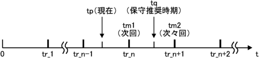
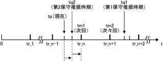
- 4 is a diagram showing an example of maintenance timing and recommended maintenance timing of the electrolytic device 200.
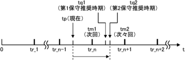
- FIG. FIG. 4 is a diagram showing another example of maintenance timing and recommended maintenance timing of the electrolytic device 200;
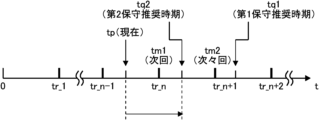
- FIG. 4 is a diagram showing another example of maintenance timing and recommended maintenance timing of the electrolytic device 200;
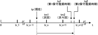
- FIG. 4 is a diagram showing another example of maintenance timing and recommended maintenance timing of the electrolytic device 200;
- FIG. 4 is a diagram showing another example of maintenance timing and recommended maintenance timing of the electrolytic device 200;
- FIG. 4 is a diagram showing another example of maintenance timing and recommended maintenance timing of the electrolytic device 200; It is a figure which shows another example of the electrolysis apparatus 200 which concerns on one Embodiment of this invention.
- FIG. 3 is a diagram showing another example of a block diagram of the driving assistance device 100 according to one embodiment of the present invention;
- 4 is a diagram showing an example of a first generation amount inference model 140;
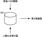
- FIG. 11 is a diagram showing an example of a second generation amount inference model 142;
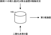
- FIG. 11 is a diagram showing an example of a third generation amount inference model 143;
- FIG. 14 is a diagram showing an example of a fourth generation amount inference model 144;
- 1 is a first flow chart including an example of a driving assistance method according to one embodiment of the present invention;
- 4 is a second flowchart including an example of a driving assistance method according to one embodiment of the present invention;
- 3 is a third flowchart including an example of a driving assistance method according to one embodiment of the present invention;
- 4 is a fourth flowchart including an example of a driving assistance method according to one embodiment of the present invention;
- 1 illustrates an example computer 2200 in which the driving assistance device 100 according to one embodiment of the invention may be embodied in whole or in part;
- FIG. 1 is a diagram illustrating an example of an electrolytic device 200 according to one embodiment of the invention.
- the electrolytic device 200 of this example includes an electrolytic bath 90 .
- the electrolysis apparatus 200 of this example is provided with a raw salt dissolution layer 113, a sedimentation separation tank 112, a filter 114, a first pressure sensor 122, a resin tower 116, a pressure sensor 123, a first introduction pipe 92, and a detection unit 99.
- the raw salt 110 is dissolved in the raw salt dissolving layer 113 .
- an aqueous solution of the raw salt 110 is charged with a chemical agent 111 that precipitates impurities that can degrade the ion exchange performance of an ion exchange membrane 84 (described later).
- the impurity Im is referred to as impurity Im.
- the impurity Im will be described later.
- the chemical 111 is, for example, Mg(OH) 2 (magnesium hydroxide) or CaCO 3 (calcium carbonate).
- the first introduction pipe 92 is connected to the electrolytic bath 90 .
- the raw salt 110 is an alkali metal chloride.
- Raw salt 110 is, for example, NaCl (sodium chloride) or KCl (potassium chloride).
- the aqueous solution of raw salt 110 is an aqueous solution of an alkali metal chloride. Let this aqueous solution be the first aqueous solution 70 .
- the raw salt 110 may contain alkaline earth metal elements.
- Alkaline earth metal elements that can be contained in the raw salt 110 are, for example, Ca (calcium), Sr (strontium), Ba (barium), or Mg (magnesium).
- the sedimentation separation tank 112 separates the aqueous solution of the raw salt 110 and the impurities Im by precipitating the impurities Im that can deteriorate the ion exchange performance of the ion exchange membrane 84 (described later).
- Impurities Im include so-called suspended solids (SS) and the like.
- SS suspended solids
- the first aqueous solution 70 from which the impurities Im have been separated is introduced into the filter 114 .
- the first aqueous solution 70 passes through the filter 114. At least part of the impurities Im remaining in the first aqueous solution 70 is removed from the first aqueous solution 70 by passing through the filter 114 .
- Filter 114 is, for example, a pre-coated pleated filter. In this example, the first aqueous solution 70 that has passed through the filter 114 is introduced into the resin tower 116 .
- the first pressure sensor 122 measures the pressure of the first aqueous solution 70.
- the first pressure sensor 122 may measure the pressure of the first aqueous solution 70 before passing through the filter 114 and the pressure of the first aqueous solution 70 after passing through the filter 114 .
- resin tower 116 is provided with ion exchange resin 118 , impurity sensor 117 , flow rate sensor 119 and image sensor 120 .
- the impurity sensor 117 detects alkaline earth metal ions, aluminum ions (Al 3+ ), nickel ions (Ni 2+ ), iron ions (Fe 2+ , Fe 3+ ), iodine ions (I ⁇ ), silicon (Si), sulfate ions. (SO 4 2 ⁇ ), suspended matter and/or organic matter are detected.
- Alkaline earth metal ions are, for example, at least one of calcium ions (Ca 2+ ), magnesium ions (Mg 2+ ), strontium ions (Sr 2+ ) and barium ions (Ba 2+ ).
- Suspended solids and organic matter are, for example, suspended solids (SS) and TOC (Total Organic Carbon).
- the impurity Im described above may refer to at least one of suspended solids (SS) and TOC (Total Organic Carbon).
- Flow sensor 119 and pressure sensor 123 will be described later.
- the first aqueous solution 70 from which at least part of the impurities Im has been removed by the filter 114 passes through the ion exchange resin 118 .
- the ion exchange resin 118 removes at least part of the impurities Im contained in the first aqueous solution 70 .
- the impurities Im contained in the first aqueous solution 70 are removed by the filter 114 and further removed by the ion exchange resin 118 . Note that the impurity sensor 117 and the image sensor 120 will be described later.
- a detector 99 is provided in the electrolytic bath 90 .
- the detector 99 will be described later.
- FIG. 2 is a diagram showing an example of an electrolytic device 200 according to one embodiment of the present invention.
- the electrolytic device 200 of this example is provided with a first introduction pipe 92 , a second introduction pipe 93 , a first discharge pipe 94 and a second discharge pipe 95 .
- the electrolytic bath 90 is a bath that electrolyzes the electrolytic solution.
- electrolytic cell 90 electrolyzes first aqueous solution 70 .
- the electrolytic cell 90 electrolyzes the NaCl (sodium chloride) aqueous solution to produce Cl 2 (chlorine), NaOH (sodium hydroxide) and H 2 (hydrogen).
- the electrolytic bath 90 may include a plurality of electrolytic cells 91 (electrolytic cells 91-1 to 91-N, where N is an integer of 2 or more). N is 50, for example.
- the first introduction pipe 92 and the second introduction pipe 93 are connected to the electrolytic cells 91-1 to 91-N, respectively.
- a first aqueous solution 70 is introduced into each of the electrolytic cells 91-1 to 91-N.
- the first aqueous solution 70 may be introduced into each of the electrolytic cells 91-1 to 91-N.
- a second aqueous solution 72 is introduced into each of the electrolytic cells 91-1 to 91-N. After passing through the second introduction pipe 93, the second aqueous solution 72 may be introduced into each of the electrolytic cells 91-1 to 91-N.
- the second aqueous solution 72 is an alkali metal hydroxide aqueous solution.
- the second aqueous solution 72 is, for example, a NaOH (sodium hydroxide) aqueous solution.
- the first outlet pipe 94 and the second outlet pipe 95 are connected to the electrolytic cells 91-1 to 91-N, respectively.
- a fourth aqueous solution 76 and a gas 78 are drawn out from each of the electrolytic cells 91-1 to 91-N.
- the fourth aqueous solution 76 and gas 78 may be led out of the electrolytic device 200 after passing through the second lead-out pipe 95 .
- the fourth aqueous solution 76 is an alkali metal hydroxide aqueous solution.
- the fourth aqueous solution 76 is a NaOH (sodium hydroxide) aqueous solution.
- Gas 78 (described below) may be H 2 (hydrogen).
- a liquid 74 and a gas 77 are drawn out from each of the electrolytic cells 91-1 to 91-N.
- the liquid 74 and the gas 77 may be led out of the electrolytic device 200 after passing through the first outlet pipe 94 .
- Liquid 74 is an aqueous solution of an alkali metal chloride.
- the first aqueous solution 70 is an aqueous NaCl (sodium chloride) solution
- the liquid 74 is an aqueous NaCl (sodium chloride) solution.
- Gas 77 (described below) may be Cl 2 (chlorine).
- a plurality of first switching units 66 and a plurality of first switching units 67 are provided in the electrolysis device 200 of this example.
- the first switching section 66-1 and the first switching section 66-2 are provided in the first introduction pipe 92 and the second introduction pipe 93, respectively.
- the first switching section 66-1 and the first switching section 66-2 control the flow rates of the first aqueous solution 70 and the second aqueous solution 72, respectively.
- the first switching section 67-1 and the first switching section 67-2 are provided in the first outlet tube 94 and the second outlet tube 95, respectively.
- the first switching section 67-1 and the first switching section 67-2 control the flow rates of the liquid 74 and the fourth aqueous solution 76, respectively.
- the first switching portion 66 and the first switching portion 67 are valves, for example.
- the first switching unit 66-1 may control the flow rate per unit time of the first aqueous solution 70 flowing through the first introduction pipe 92, or the integrated value of the flow rate over a predetermined period of time. The same applies to the first switching section 66-2, the first switching section 67-1, and the first switching section 67-2.
- a flow rate sensor 130 is provided in the electrolytic device 200 of this example.
- the flow rate sensor 130 measures at least one of the flow rate of the first aqueous solution 70 passing through the first introduction pipe 92 and the flow rate of the second aqueous solution 72 passing through the second introduction pipe 93 .
- the flow sensor 130 may be provided on the first introduction pipe 92 and the second introduction pipe 93 .
- a second pressure sensor 132 is provided in the electrolytic device 200 of the present example.
- the second pressure sensor 132 measures at least one of the pressure of chlorine gas (Cl 2 ) in the anode chamber 79 (described later) and the pressure of hydrogen gas (H 2 ) in the cathode chamber 98 (described later).
- a second pressure sensor 132 may be provided on the first outlet tube 94 and the second outlet tube 95 .
- FIG. 3 is a diagram showing an example of details of one electrolytic cell 91 in FIG.
- the electrolytic cell 90 has an anode compartment 79 , an anode 80 , a cathode compartment 98 , a cathode 82 and an ion exchange membrane 84 .
- one electrolytic cell 91 has an anode compartment 79 , an anode 80 , a cathode compartment 98 , a cathode 82 and an ion exchange membrane 84 .
- Anode chamber 79 and cathode chamber 98 are provided inside electrolytic cell 91 .
- the anode chamber 79 and cathode chamber 98 are separated by an ion exchange membrane 84 .
- An anode 80 is arranged in the anode chamber 79 .
- a cathode 82 is arranged in the cathode chamber 98 .
- a first introduction pipe 92 and a first discharge pipe 94 are connected to the anode chamber 79 .
- a second introduction tube 93 and a second lead-out tube 95 are connected to the cathode chamber 98 .
- a first aqueous solution 70 is introduced into the anode chamber 79 .
- a second aqueous solution 72 is introduced into the cathode chamber 98 .
- the detector 99 (see this figure and FIG. 1) may be provided in the anode chamber 79 .
- the detection unit 99 detects alkaline earth metal ions contained in the first aqueous solution 70, aluminum ions (Al 3+ ), nickel ions (Ni 2+ ), iron ions (Fe 2+ , Fe 3+ ), iodine ions (I ⁇ ), At least one of silicon (Si), sulfate ion (SO 4 2 ⁇ ), suspended solids and organic matter is detected.
- detection targets Db detection targets by the detection unit 99 are referred to as detection targets Db.
- the ion-exchange membrane 84 is a membrane-like substance that blocks the passage of ions having the same sign as the ions placed on the ion-exchange membrane 84 and allows only ions of the opposite sign to pass.
- the first aqueous solution 70 is a NaCl (sodium chloride) aqueous solution
- the ion exchange membrane 84 allows passage of Na + (sodium ions) and blocks passage of Cl ⁇ (chloride ions).
- Anode 80 and cathode 82 may be maintained at predetermined positive and negative potentials, respectively.
- the first aqueous solution 70 introduced into the anode chamber 79 and the second aqueous solution 72 introduced into the cathode chamber 98 are electrolyzed by the potential difference between the anode 80 and the cathode 82 .
- the following chemical reactions take place. [Chemical Formula 1] 2Cl ⁇ ⁇ Cl 2 +2e ⁇
- the first aqueous solution 70 is a NaCl (sodium chloride) aqueous solution
- NaCl (sodium chloride) is ionized into Na + (sodium ions) and Cl ⁇ (chloride ions).
- Cl 2 (chlorine) gas is generated by the chemical reaction shown in Chemical Formula 1.
- Gas 77 (the Cl 2 (chlorine) gas) and liquid 74 may be drawn from the anode chamber 79 .
- Na + (sodium ions) move from the anode chamber 79 to the cathode chamber 98 after passing through the ion exchange membrane 84 due to the attractive force from the cathode 82 .
- the liquid 73 may stay in the anode chamber 79 .
- Liquid 73 is an aqueous solution of alkali metal chloride.
- the first aqueous solution 70 is an aqueous NaCl (sodium chloride) solution
- the liquid 73 is an aqueous NaCl (sodium chloride) solution.
- the Na + (sodium ion) and Cl ⁇ (chloride ion) concentrations of the liquid 73 may be lower than the Na + (sodium ion) and Cl ⁇ (chloride ion) concentrations of the first aqueous solution 70 .
- the second aqueous solution 72 is a NaOH (sodium hydroxide) aqueous solution
- NaOH sodium hydroxide
- NaOH sodium hydroxide
- OH ⁇ hydrooxide ions
- the gas 78 the H 2 (hydrogen) gas
- the fourth aqueous solution 76 may be discharged from the cathode chamber 98 .
- the liquid 75 may stay in the cathode chamber 98 .
- the liquid 75 is a NaOH (sodium hydroxide) aqueous solution.
- the cathode chamber 98 contains OH ⁇ (hydroxide ions) produced by the chemical reaction represented by Chemical Formula 2 and Na + A liquid 75 in which (sodium ions) is dissolved remains.
- FIG. 4 is an enlarged view of the vicinity of the ion exchange membrane 84 in the electrolytic cell 91 shown in FIG.
- Anion groups 86 are immobilized on the ion exchange membrane 84 of this example. Since anions are repelled by the anion groups 86 , they are less likely to pass through the ion exchange membrane 84 .
- the first aqueous solution 70 (see FIG. 3) is a NaCl (sodium chloride) aqueous solution, the anions are Cl ⁇ (chloride ions).
- the cations 71 are not repelled by the anionic groups 86 and thus can pass through the ion exchange membrane 84 .
- the first aqueous solution 70 is a NaCl (sodium chloride) aqueous solution
- the cations 71 are Na + (sodium ions).
- FIG. 5 is a diagram showing an example of a block diagram of the driving support device 100 according to one embodiment of the present invention.
- the driving assistance device 100 assists the operation of the electrolytic device 200 (see FIGS. 1 and 2).
- Driving support device 100 includes prediction unit 10 and provision unit 14 .
- the driving assistance device 100 may include a determination unit 12 , a state acquisition unit 16 , a control unit 20 and an input unit 22 .
- the driving assistance device 100 is, for example, a computer including a CPU, memory, interface, and the like.
- the control unit 20 may be the CPU.
- the CPU may be the control unit 20 and the determination unit 12 .
- the driving assistance device 100 is a computer, the computer may be installed with a driving assistance program for executing a driving assistance method described later, and the driving assistance program for making the computer function as the driving assistance device 100 is installed. may be installed.
- Driving support device 100 may be a tablet computer.
- the state acquisition unit 16 acquires the state of the object 210 in the electrolytic device 200 .
- the target object 210 refers to parts, members, etc. included in the electrolysis device 200 and preferably maintained periodically.
- the object 210 includes the raw salt 110, the filter 114, the ion exchange resin 118, the first aqueous solution 70, the first inlet pipe 92 (see FIG. 1 above), the second inlet pipe 93, the first outlet pipe 94, and the second outlet.
- a tube 95, a first switching portion 66, a first switching portion 67 (see FIG. 2 above), an ion exchange membrane 84, an anode 80 and a cathode 82 (see FIG. 3 above) may be included.
- the input unit 22 is, for example, a mouse, a keyboard, or the like. If the driving assistance device 100 is a tablet computer, the input unit 22 may be a touch panel of the tablet computer.
- the providing unit 14 provides information on maintenance of the object 210 (described later).
- the providing unit 14 may be a display, monitor, or the like that displays the information, or may be a speaker that outputs the information by voice.
- FIG. 6 is a diagram showing an example of maintenance timing and recommended maintenance timing for the electrolytic device 200.
- the maintenance timing of the electrolytic device 200 is defined as maintenance timing tr.
- the maintenance timing tr is predetermined.
- the maintenance timing tr may be regular and constant.
- the maintenance timing tr may be the timing of planned shutdown of the electrolysis device 200 or the timing of regular maintenance of the electrolysis device 200 .
- the maintenance time tr is a time when the object 210 (described later) can be maintained.
- FIG. 6 shows the first maintenance timing tr1 to the (n+2)th maintenance timing tr_n+2 after the operation of the electrolytic device 200 is started.
- time tp is a time between maintenance timing tr_n ⁇ 1 and maintenance timing tr_n. Seen from the time tp, the next maintenance timing tr is set as the first maintenance timing tm1, and the next maintenance timing tr is set as the second maintenance timing tm2. The second maintenance timing tm2 is later than the first maintenance timing tm1.
- a state S of the object 210 in which maintenance is preferable is referred to as a recommended maintenance state Sn.
- the recommended maintenance state Sn may include a state in which maintenance of the target object 210 is required and a state in which maintenance is not necessarily required but is preferably performed.
- the time when it is preferable to perform maintenance of the electrolytic device 200 is defined as a recommended maintenance time tq.
- the recommended maintenance time tq may include a time when maintenance of the target object 210 is required and a time when maintenance is not necessarily required but preferably performed.
- the target object 210 being in the recommended maintenance state refers to a state in which the operating cost of the electrolysis device 200 when the target object 210 is replaced is lower than the operating cost of the electrolysis device 200 when the target object 210 is not replaced. good too.
- the operating cost may include the cost of electricity associated with the operation of the electrolytic device 200 and the cost of the object 210 when the object 210 is replaced.
- the prediction unit 10 predicts the recommended maintenance timing tq at which the object 210 in the electrolytic device 200 will be in the recommended maintenance state Sn.
- the determination unit 12 determines the relationship between the first maintenance timing tm1 and the recommended maintenance timing tq, and the relationship between the second maintenance timing tm2 and the recommended maintenance timing tq.
- the providing unit 14 determines that the target object 210 (See FIG. 5) to provide information recommending that the maintenance be performed at the first maintenance timing tm1.
- the user of the driving support device 100 is notified that the object 210 will not enter the recommended maintenance state Sn at the first maintenance timing tm1, but is expected to enter the recommended maintenance state Sn before the second maintenance timing tm2. It is perceptible at the current time tp.
- the information that recommends maintenance of the target object 210 may be information that recommends replacement of the target object 210 or information that recommends measuring the life of the target object 210 .
- the providing unit 14 may provide the information recommending maintenance of the object 210 at the current time tp, at the first maintenance time tm1, or at the recommended maintenance time tq from the current time tp. may be provided continuously until
- FIG. 7 is a diagram showing another example of maintenance timing and recommended maintenance timing for the electrolytic device 200.
- the recommended maintenance state Sn may be predetermined.
- the predetermined recommended maintenance state Sn is, for example, the specified life state of the target object 210 (see FIG. 5).
- the predetermined recommended maintenance state Sn may be the state S of the object 210 that is difficult for the state acquisition unit 16 to acquire.
- Objects 210 for which it is difficult for the state acquisition unit 16 to acquire the state S are, for example, the filter 114, the ion exchange resin 118, and the like.
- the recommended maintenance time tq at which the predetermined recommended maintenance state Sn is achieved is assumed to be the first recommended maintenance time tq1.
- the prediction unit 10 may predict, as the recommended maintenance time tq, a first recommended maintenance time tq1 at which the object 210 will be in the recommended maintenance state Sn.
- the first recommended maintenance timing tq1 may be the specified lifetime timing of the object 210 .
- the specified life time may be input through the input unit 22 (see FIG. 5).
- the prediction unit 10 sets the target object 210 as maintenance recommended time tq.
- the second recommended maintenance time when the state Sn is reached may be predicted.
- the recommended maintenance timing tq predicted based on the state S is defined as a second recommended maintenance timing tq2.
- FIG. 7 is an example of the second recommended maintenance timing tq2 predicted at the current time tp.
- the first maintenance timing tq1 and the second maintenance timing tq2 may be different.
- the state acquisition unit 16 may acquire current efficiency CE (described later) of the electrolytic cell 90 .
- the prediction unit 10 may predict the second recommended maintenance time tq2 based on the current efficiency CE.
- the production amount per hour of the product produced by the electrolytic cell 90 is assumed to be production amount Pa' [T/h], the production amount per day is Pa, and the molecular weight of the product is assumed to be molecular weight M [kg/kmol].
- the production amount Pa' per day preferably satisfies the following formula (1).
- the prediction unit 10 may predict when the inequality of Equation 1 will no longer be satisfied.
- the second recommended maintenance timing tq2 may be a timing when the inequality of Equation 1 is no longer satisfied.
- the state acquisition unit 16 may acquire the voltage CV (described later) of the electrolytic cell 90.
- the prediction unit 10 may predict the second recommended maintenance time tq2 based on the voltage CV.
- the voltage CV (described later) may increase.
- the prediction unit 10 (see FIG. 5) predicts that the coating amount of the anode 80 and the cathode 82 (see FIG. 3) is may predict the time when a predetermined percentage will be reached.
- the ratio is, for example, 30%.
- the state acquisition unit 16 may acquire the impurity concentration in the product produced by the electrolytic cell 90 .
- the impurities are at least one of NaCl (sodium chloride) and NaClO 3 (sodium chlorate).
- the product is Cl 2 (chlorine)
- the impurity is O 2 (oxygen).
- the prediction unit 10 may predict the second recommended maintenance time tq2 based on the concentration of impurities in the product produced by the electrolytic cell 90 .
- the second recommended maintenance time tq2 may be a time when the impurity concentration becomes equal to or higher than a predetermined concentration.
- the state acquisition unit 16 may acquire the impurity concentration of the gas 78 (see FIG. 3). If the gas 78 is H2 (hydrogen), the impurity is Cl2 (chlorine).
- the prediction unit 10 may predict the second recommended maintenance timing tq2 based on the impurity concentration of the gas 78 (see FIG. 3).
- the second recommended maintenance time tq2 may be a time when the impurity concentration becomes equal to or higher than a predetermined concentration. If the gas 78 is H 2 (hydrogen) and the impurity is Cl 2 (chlorine), the concentration may be a predetermined concentration relative to the explosive limit concentration at which an excess of Cl 2 (chlorine) may cause an explosion. The concentration is, for example, 0.3%.
- the state acquisition unit 16 may acquire at least one of the temperature of the liquid 74 and the temperature of the fourth aqueous solution 76 measured by the temperature sensor 135 (described later).
- the prediction unit 10 may predict the second recommended maintenance time tq2 based on the temperature of the liquid 74 or the temperature of the fourth aqueous solution 76 .
- the second recommended maintenance time tq2 may be a time when the temperature of the liquid 74 or the temperature of the fourth aqueous solution 76 is equal to or lower than a predetermined first temperature, or a time when the temperature is equal to or higher than a predetermined second temperature. .
- the first temperature is 80° C., for example.
- the second temperature is 87° C., for example.
- the state acquisition unit 16 may acquire at least one of a first pH (described later) and a second pH (described later) measured by a pH sensor 136 (described later).
- the prediction unit 10 may predict the second recommended maintenance timing tq2 based on the first pH or the second pH.
- the second recommended maintenance time tq2 may be a time when at least one of the hydrogen ion concentration of the first aqueous solution 70 and the hydrogen ion concentration of the second aqueous solution 72 becomes 0.15 N (regulation) or more.
- the state acquisition unit 16 may continuously acquire the state S of the object 210 (see FIG. 5) from the current time tp to the second recommended maintenance time tq2.
- the prediction unit 10 may continuously predict the second recommended maintenance time tq2.
- the second recommended maintenance timing tq2 may be updated over time.
- the state acquisition unit 16 may acquire the state S of the target object 210 (see FIG. 5) regardless of whether the electrolytic device 200 is in operation or at maintenance time tr.
- the prediction unit 10 may predict the second recommended maintenance time tq2 regardless of whether the electrolytic device 200 is in operation or the maintenance time tr.
- the state acquisition unit 16 may acquire the state S of the target object 210 at the first maintenance timing tm1.
- the prediction unit 10 may predict the second recommended maintenance time tq2 based on the state S of the object 210 measured at the first maintenance time tm1.
- FIG. 8 is a diagram showing another example of maintenance timing and recommended maintenance timing for the electrolytic device 200.
- FIG. FIG. 8 shows an example when the determination unit 12 (see FIG. 5) determines that the first recommended maintenance time tq1 is after the first maintenance time tm1 and before the second maintenance time tm2.
- the state acquisition unit 16 may measure the state S of the object 210 (see FIG. 5) at the first maintenance timing tm1.
- the prediction unit 10 (see FIG. 5) may predict the second recommended maintenance timing tq2 at the first maintenance timing tm1.
- the first maintenance time tq1 is the recommended maintenance time tq at which the object 210 (see FIG. 5) is in the predetermined recommended maintenance state Sn.
- the first recommended maintenance time tq1 is later than the first maintenance time tm1 and before the second maintenance time tm2
- there is a probability that the target object 210 is approaching the predetermined recommended maintenance state Sn. is high. Therefore, by predicting the second recommended maintenance time tq2 at the first maintenance time tm1 by the prediction unit 10 (see FIG. 5), the user of the driving support device 100 can perform the target based on the state S at the first maintenance time tm1.
- the recommended maintenance timing tq that is, the second recommended maintenance timing tq2 of the object 210 can be recognized. This makes it easier for the user of the driving support device 100 to determine whether or not to replace the object 210 at the first maintenance timing tm1.
- FIG. 9 is a diagram showing another example of maintenance timing and recommended maintenance timing for the electrolytic device 200.
- FIG. FIG. 9 shows that the determination unit 12 (see FIG. 5) determines that the first recommended maintenance time tq1 is later than the second maintenance time tm2, and that the second recommended maintenance time tq2 is later than the first maintenance time tm1. This is an example of a case where it is determined to be later than the second maintenance timing tm2 and before the second maintenance timing tm2.
- the providing unit 14 may provide information recommending maintenance of the object 210 (see FIG. 5) at the first maintenance timing tm1.
- the providing unit 14 may provide the information at the current time tp.
- the object 210 reaches the recommended maintenance state Sn earlier than the recommended maintenance time tq (that is, the first recommended maintenance time tq1) when the recommended maintenance state Sn is reached.
- the providing unit 14 provides information recommending maintenance of the target object 210 at the first maintenance timing tm1, so that the user of the driving support device 100 can perform maintenance at the first maintenance timing tm1. maintenance of the object 210 becomes easier.
- the object 210 may include multiple types of parts, members, etc. included in the electrolytic device 200 .
- the prediction unit 10 predicts the first recommended maintenance timing tq1 and the second recommended maintenance timing tq2 for the same object 210 (eg ion exchange membrane 84). you can
- FIG. 10 is a diagram showing another example of maintenance timing and recommended maintenance timing for the electrolytic device 200.
- FIG. FIG. 10 shows an example in which the determination unit 12 (see FIG. 5) determines that the first recommended maintenance time tq1 and the second recommended maintenance time tq2 are after the second maintenance time tm2.
- filter 114 and resin tower 116 remove impurities Im.
- the alkaline earth metal contained in the raw salt 110 is highly likely to be carbonate.
- the detection unit 99 detects the detection target Db in the first aqueous solution 70 (see FIG. 3)
- the impurity Im is introduced into the electrolytic cell 90 after passing through the filter 114 and the resin tower 116.
- the equivalent amount of the drug 111 is less than the equivalent amount of the alkaline earth metal contained in the raw salt 110 .
- the pressure of the first aqueous solution 70 before passing through the filter 114 (see FIG. 1) measured by the first pressure sensor 122 (see FIG. 1) is defined as a first pressure P1
- the pressure of the first aqueous solution after passing through the filter 114 70 is set to the second pressure P2.
- the determination unit 12 may determine whether the difference between the first pressure P1 and the second pressure P2 exceeds a predetermined threshold difference.
- the filter 114 removes carbonates of poorly water-soluble alkaline earth metals. Therefore, when the carbonate accumulates in the filter 114, the performance of the filter 114 to remove the carbonate tends to deteriorate. As the carbonate accumulates in the filter 114, the second pressure P2 tends to become smaller than the first pressure P1.
- the predetermined threshold difference may be a difference at which the performance of the filter 114 to remove the carbonate is greater than or equal to a predetermined performance.
- the providing unit 14 sets the filter 114 may provide information that recommends updating the Updating the filter 114 may refer to removing impurities Im accumulated in the filter 114 or may refer to replacement of the filter 114 . This makes it easier for the user of the driving support device 100 to update the filter 114 at an appropriate time. Filter 114 may be updated at maintenance timing tr.
- the ion exchange resin 118 may be regenerated. As noted above, the ion exchange resin 118 removes alkaline earth metal ions. Therefore, when alkaline earth metal ions adhere to the anion groups 86 of the ion exchange resin 118, the ability of the ion exchange resin 118 to remove the alkaline earth metal ions tends to decrease. Regenerating the ion exchange resin 118 may refer to removing the alkaline earth metal ions attached to the anionic groups 86 .
- a flow rate sensor 119 measures the flow rate of the pure water.
- the determination unit 12 may calculate the backwash rate of the ion exchange resin 118 based on the flow rate of pure water measured by the flow rate sensor 119 .
- the determination unit 12 may determine whether the backwashing speed of the ion exchange resin 118 exceeds a predetermined backwashing speed threshold. As more suspended solids or organic matter accumulates on the ion exchange resin 118, the backwash rate of the ion exchange resin 118 tends to increase.
- the predetermined backwashing speed threshold value may be a backwashing speed at which the performance of the ion exchange resin 118 removing the impurities Im is equal to or higher than a predetermined performance.
- the providing unit 14 provides information recommending renewal of the ion exchange resin 118.
- you can Renewal of the ion-exchange resin 118 may refer to removing the alkaline earth metal impurities Im accumulated in the ion-exchange resin 118 by flowing pure water, and may refer to replacement of the ion-exchange resin 118. . This makes it easier for the user of the driving support device 100 to update the ion exchange resin 118 at an appropriate time.
- the ion exchange resin 118 may be renewed at the maintenance timing tr.
- regeneration of ion exchange resin 118 may be performed by introducing a chemical such as HCl (hydrochloric acid) or NaOH (sodium hydroxide) into resin tower 116.
- the determination unit 12 may determine the introduction amount of the chemical solution.
- the providing unit 14 may provide information indicating that the introduced amount of the chemical solution is abnormal.
- the image sensor 120 may be provided on the resin window in the resin tower 116 .
- An image sensor 120 (see FIG. 1) measures the resin height in the resin tower.
- the determination unit 12 may determine the resin height based on the resin height measured by the image sensor 120 .
- the providing unit 14 may provide information to the effect that regeneration of the ion exchange resin 118 is recommended. .
- Regeneration of ion exchange resin 118 may include addition or replacement of ion exchange resin 118 .
- the providing unit 14 may provide information recommending replacement of the ion exchange resin 118 .
- the state acquisition unit 16 may acquire the regeneration cycle of the ion exchange resin 118 .
- the providing unit 14 may provide information recommending replacement of the ion exchange resin 118 .
- the pressure sensor 123 measures the pressure of the first aqueous solution 70 introduced into the resin tower 116 and the pressure of the first aqueous solution 70 discharged from the resin tower 116 .
- the determination unit 12 determines that the difference between the pressure of the first aqueous solution 70 introduced into the resin tower 116 and the pressure of the first aqueous solution 70 discharged from the resin tower 116 measured by the pressure sensor 123 is determined in advance. It may be determined whether a pressure threshold has been exceeded. When the determining unit 12 determines that the difference exceeds the pressure threshold value, the providing unit 14 may provide information recommending replacement of the ion exchange resin 118 .
- the determination unit 12 determines whether the concentration of SO 4 2 ⁇ (sulfate ions) in the first aqueous solution 70 (see FIGS. 1 and 3) exceeds a predetermined sulfate ion concentration threshold. good.
- the concentration of SO 4 2 ⁇ (sulfate ions) in the first aqueous solution 70 is equal to or lower than a predetermined sulfate ion concentration threshold.
- the impurity sensor 117 (see FIG. 1) measures the concentration of alkaline earth metal ions.
- a removal device for removing impurities Im may be provided outside the resin tower 116 . If the concentration of the impurity Im measured by the impurity sensor 117 exceeds a predetermined concentration threshold, the impurity Im may be removed by the removal device.
- the state acquisition unit 16 obtains at least one of the flow rate of the first aqueous solution 70 (see FIG. 2) and the flow rate of the second aqueous solution 72 (see FIG. 2) measured by the flow sensor 130 (see FIG. 2). may be obtained.
- the state acquisition unit 16 may acquire the flow rate F1 and the flow rate F2 while the electrolytic device 200 is in operation.
- the determination unit 12 may determine whether the flow rate F1 or the flow rate F2 is within a predetermined flow rate range. This flow rate range is referred to as a flow rate range Fr. When the flow rate F1 is not within the flow rate range Fr, salt is likely to precipitate in the electrolytic bath 90 . When the flow rate F1 is not within the flow rate range Fr, electrolysis of water is likely to occur in the electrolytic cell 90 .
- the flow rate range Fr may include an upper limit flow rate and a lower limit flow rate of the flow rate range Fr.
- the providing unit 14 provides information recommending maintenance of the object 210 (see FIG. 5). good.
- the object 210 is a part, member, or the like included in the electrolysis device 200 and preferably maintained on a regular basis. This makes it easier for the user of the driving support device 100 to maintain the object 210 at the maintenance timing tr.
- the determination unit 12 controls the first switching unit 66 and the first switching unit 67 (see FIG. 2) to It may be determined whether F1 and the flow rate F2 can be controlled within the flow rate range Fr.
- the providing unit 14 switches the first introduction pipe 92, the second introduction pipe 93, the first switching unit Information recommending repair or replacement of 66 and first switching unit 67 may be provided.
- the determination unit 12 determines that the flow rate F1 and the flow rate F2 can be controlled within the flow rate range Fr, the user of the driving support device 100 switches the first switching unit 66 and the first switching unit 67 (see FIG. 2 ) at the maintenance timing tr. ) may be manually controlled.
- FIG. 11 is a diagram showing another example of the maintenance timing and recommended maintenance timing of the electrolytic device 200.
- FIG. FIG. 11 shows that the determination unit 12 (see FIG. 5) determines that the first recommended maintenance time tq1 is later than the second maintenance time tm2, and that the second recommended maintenance time tq2 is later than the first maintenance time tm1. This is an example of a case where it is determined to be before When it is determined that the first recommended maintenance time tq1 is after the second maintenance time tm2 and the second recommended maintenance time tq2 is before the first maintenance time tm1, the control unit 20 , the second recommended maintenance timing tq2 may be delayed to the first maintenance timing tm1. Control unit 20 may delay second recommended maintenance timing tq2 to first maintenance timing tm1 by controlling first switching unit 66 and first switching unit 67 .
- the state acquisition unit 16 may acquire the state of the object 210 at the first maintenance timing tm1.
- the state acquisition unit 16 may postpone acquisition of the state of the object 210 until the first maintenance timing tm1.
- the state acquisition unit 16 obtains at least one of a current efficiency CE (described later), a voltage CV (described later), a flow rate F1, a flow rate F2, a temperature T1 (described later), a temperature T2 (described later), a pressure Pr1 (described later), and a pressure Pr2 (described later).
- acquisition of the state of the object 210 may be deferred until the first maintenance timing tm1 by changing one.
- FIG. 12 is a diagram showing another example of the electrolytic device 200 according to one embodiment of the present invention.
- the electrolytic device 200 of this example includes a temperature sensor 134, a temperature sensor 135, a pH sensor 136, a third introduction pipe 97, a fourth introduction pipe 102, a second switching section 68, a third switching section 69, and a heat exchanger 96. is provided.
- the electrolytic device 200 of this example differs from the electrolytic device 200 shown in FIG. 2 in this respect.
- a third aqueous solution 81 that is an acidic aqueous solution passes through the third introduction pipe 97 .
- the third aqueous solution 81 is, for example, HCl (hydrochloric acid).
- the second switching portion 68 is provided on the third introduction pipe 97 .
- HCl (hydrochloric acid) is introduced into the first introduction pipe 92 through the third introduction pipe 97 .
- the fourth introduction pipe 102 is connected to the heat exchanger 96 and the second introduction pipe 93.
- the fourth aqueous solution 76 passes through the fourth introduction pipe 102 .
- a heat exchanger 96 cools the fourth aqueous solution 76 .
- the cooled fourth aqueous solution 76 is introduced into the second introduction pipe 93 .
- the temperature sensor 134 measures at least one of the temperature of the first aqueous solution 70 and the temperature of the second aqueous solution 72 .
- the temperature sensor 134 measures at least one of the temperature of the first aqueous solution 70 passing through the first introduction pipe 92 and the temperature of the second aqueous solution 72 passing through the second introduction pipe 93 .
- the temperature sensor 134 may be provided on the first introduction pipe 92 and the second introduction pipe 93 .
- the temperature of the first aqueous solution 70 is assumed to be temperature T1.
- the temperature of the second aqueous solution 72 is assumed to be temperature T2.
- the temperature sensor 135 measures at least one of the temperature of the liquid 74 and the temperature of the fourth aqueous solution 76 .
- temperature sensor 135 measures at least one of the temperature of liquid 74 passing through first outlet tube 94 and the temperature of fourth aqueous solution 76 passing through second outlet tube 95 .
- a temperature sensor 135 may be provided on the first outlet tube 94 and the second outlet tube 95 .
- the state acquisition unit 16 may acquire at least one of the temperature T1 and the temperature T2 measured by the temperature sensor 134.
- the state acquisition unit 16 may acquire the temperature T1 and the temperature T2 while the electrolytic device 200 is in operation.
- the determination unit 12 may determine whether the temperature T1 or the temperature T2 exceeds a predetermined temperature threshold. This temperature threshold is set as a threshold Tth. Threshold Tth may be the upper limit of temperature T1 and temperature T2 when electrolytic device 200 is operating normally.
- the providing unit 14 provides information recommending maintenance of the object 210 (see FIG. 5).
- the object 210 is a part, member, or the like included in the electrolysis device 200 and preferably maintained on a regular basis. This makes it easier for the user of the driving support device 100 to maintain the object 210 at the maintenance timing tr.
- the determination unit 12 determines that the temperature T1 or the temperature T2 exceeds the threshold value Tth, the determination unit 12 controls the third switching unit 69 to reduce the temperature T1 and the temperature T2 to the threshold value Tth or less. It may be determined whether it is controllable.
- the providing unit 14 (see FIG. 5) repairs or replaces the fourth introduction pipe 102 and the third switching unit 69. You may provide recommended information. This makes it easier for the user of the driving support device 100 to repair or replace the fourth introduction pipe 102 and the third switching unit 69 at the maintenance timing tr.
- the pH sensor 136 measures at least one of the pH of the first aqueous solution 70 and the pH of the second aqueous solution 72 .
- the pH sensor 136 measures at least one of the pH of the first aqueous solution 70 passing through the first introduction pipe 92 and the pH of the second aqueous solution 72 passing through the second introduction pipe 93 .
- the pH sensor 136 may be provided on the first introduction pipe 92 and the second introduction pipe 93 . Let the pH of the 1st aqueous solution 70 be 1st pH. Let the pH of the second aqueous solution 72 be the second pH.
- the state acquisition unit 16 may acquire at least one of the first pH and the second pH measured by the pH sensor 136.
- the state acquisition unit 16 may acquire the first pH and the second pH while the electrolytic device 200 is in operation.
- the determination unit 12 may determine whether the first pH is less than a predetermined first pH threshold or whether the second pH exceeds a predetermined second pH threshold. Let the first pH threshold be the threshold Pth1. Let the second pH threshold be the threshold Pth2.
- the threshold Pth1 and the threshold Pth2 may be the lower limit of the first pH and the upper limit of the second pH, respectively, when the electrolytic device 200 is operating normally.
- the providing unit 14 may provide information recommending maintenance of object 210 (see FIG. 5).
- the determination unit 12 determines that the first pH is less than the threshold Pth1 or determines that the second pH exceeds the threshold Pth2, the determination unit 12 switches the second switching unit 68 (see FIG. 2 ), it may be determined whether the first pH can be controlled to the threshold value Pth1 or more and whether the second pH can be controlled to the threshold value Pth2 or less.
- the providing unit 14 determines that the first pH cannot be controlled to the threshold value Pth1 or more and determines that the second Ph cannot be controlled to the threshold value Pth2 or less.
- Information recommending repair or replacement of the No. 3 introduction tube 97 and the second switching unit 68 may be provided. This makes it easier for the user of the driving support device 100 to repair or replace the third introduction pipe 97 and the second switching unit 68 at the maintenance timing tr.
- the second pressure sensor 132 measures at least one of the pressure of chlorine gas (Cl 2 ) in the anode chamber 79 (see FIG. 3) and the pressure of hydrogen gas (H 2 ) in the cathode chamber 98 (see FIG. 3).
- the pressure of chlorine gas (Cl 2 ) is assumed to be pressure Pr1.
- the pressure of hydrogen gas (H 2 ) is assumed to be pressure Pr2.
- the state acquisition unit 16 may acquire at least one of the pressure Pr1 and the pressure Pr2 measured by the second pressure sensor 132.
- the state acquisition unit 16 may acquire the pressure Pr1 and the pressure Pr2 while the electrolytic device 200 is in operation.
- the determination unit 12 may determine whether the pressure Pr1 or the pressure Pr2 exceeds a predetermined pressure threshold.
- the pressure threshold is set as a threshold Prth.
- the threshold Prth may be the upper limit of the pressure P1 and the pressure P2 when the electrolytic device 200 is operating normally.
- the providing unit 14 provides information recommending maintenance of the object 210 (see FIG. 5). you can
- the determination unit 12 determines that the pressure P1 or the pressure P2 exceeds the threshold value Prth, the determination unit 12 controls the first switching unit 66 and the first switching unit 67 (see FIG. 2) to It may be determined whether Pr1 and pressure Pr2 can be controlled below the threshold value Prth.
- the providing unit 14 controls the anode chamber 79 (see FIG. 3) and the cathode chamber 98 (see FIG. 3). ) may provide information recommending maintenance. This makes it easier for the user of the driving support device 100 to perform maintenance on the anode chamber 79 (see FIG. 3) and the cathode chamber 98 (see FIG. 3) at the maintenance timing tr.
- the state acquisition unit 16 may acquire the current efficiency of the electrolytic cell 90.
- the current efficiency of the electrolytic cell 90 is defined as current efficiency CE.
- Current efficiency CE refers to the ratio of the actual output of the product produced by the electrolytic cell 90 to the theoretical output.
- the state acquisition unit 16 may acquire the current efficiency CE while the electrolytic device 200 is in operation.
- the prediction unit 10 (see FIG. 5) predicts the current efficiency CE at the second maintenance timing tm2 (see FIGS. 6 to 11) based on the current efficiency CE acquired by the state acquisition unit 16 (see FIG. 5). you can The prediction unit 10 may predict the current efficiency CE at the second maintenance timing tm2 at the time tp (see FIGS. 6 to 11) based on the current efficiency CE acquired by the state acquisition unit 16. FIG. When the ion exchange performance of the ion exchange membrane 84 deteriorates, the current efficiency CE may decrease.
- the determination unit 12 may determine whether the current efficiency CE predicted by the prediction unit 10 is less than the current efficiency predetermined at the second maintenance timing tm2.
- the current efficiency threshold is set as a threshold CEth.
- the threshold CEth may be the lower limit of the current efficiency CE at which the electrolytic device 200 can operate normally, or may be the current efficiency CE for achieving the target production volume of the product produced by the electrolytic cell 90. .
- the providing unit 14 replaces the ion exchange membrane 84 (see FIG. 3) with Information that recommends updating at the first maintenance timing tm1 (see FIGS. 6 to 11) may be provided. This makes it easier for the user of the driving support device 100 to update the ion exchange membrane 84 before the current efficiency CE becomes less than the threshold CEth.
- Renewal of the ion exchange membrane 84 may refer to removing impurities accumulated in the ion exchange membrane 84 or may refer to replacing the ion exchange membrane 84 .
- Impurities Im introduced into the anode chamber 79 or the cathode chamber 98 may accumulate in the ion exchange membrane 84 .
- the state acquisition unit 16 may acquire the voltage of the electrolytic cell 90. Let the voltage of the electrolytic cell 90 be voltage CV. The state acquisition unit 16 may acquire the voltage CV while the electrolytic device 200 is in operation.
- the prediction unit 10 may predict the voltage CV at the second maintenance timing tm2 (see FIGS. 6 to 11) based on the voltage CV acquired by the state acquisition unit 16. FIG. Based on the voltage CV acquired by the state acquisition unit 16, the prediction unit 10 (see FIG. 5) predicts the voltage CV at the second maintenance timing tm2 (see FIGS. 6 to 11) at the time tp (see FIGS. 6 to 11). ).
- the voltage CV may increase.
- the coating state of the metal or the like coated on the surfaces of the anode 80 and the cathode 82 see FIG. 3) deteriorates, the voltage CV may increase.
- the determination unit 12 may determine whether the voltage CV predicted by the prediction unit 10 exceeds a voltage threshold predetermined at the second maintenance timing tm2.
- the voltage threshold is set as a threshold CVth.
- the threshold CVth may be the upper limit of the voltage CV at which the electrolytic device 200 can operate normally.
- the providing unit 14 sets the ion exchange membrane 84 (see FIG. 3)
- the anode Information may be provided to recommend that at least one of 80 and cathode 82 (see FIG. 3) be updated at first maintenance time tm1 (see FIGS. 6-11). This makes it easier for the user of the driving support device 100 to update at least one of the ion exchange membrane 84, the anode 80 and the cathode 82 before the voltage CV exceeds the threshold CVth.
- the user of the driving support device 100 manually updates at least one of the ion exchange membrane 84 (see FIG. 3), the anode 80 and the cathode 82 (see FIG. 3) at the first maintenance timing tm1 (see FIGS. 6 to 11).
- the user may input the coating amount into the driving assistance device 100 through the input unit 22 (see FIG. 5).
- Threshold Ath may be a specification value for anode 80 and cathode 82 .
- the providing unit 14 When the coating amount of the anode 80 and the cathode 82 is less than the threshold value Ath at the first maintenance timing tm1 (see FIGS. 6 to 11), the providing unit 14 (see FIG. 5) performs the second maintenance timing tm2 (see FIGS. 6 to 11 11) may be provided with information recommending that at least one of the anode 80 and cathode 82 (see FIG. 3) be renewed.
- the coating amount of the anode 80 and the cathode 82 When the coating amount of the anode 80 and the cathode 82 is equal to or greater than the threshold value Ath at the first maintenance time tm1 (see FIGS. 6 to 11), the providing unit 14 (see FIG. 5) performs the second maintenance time tm2 (see FIGS. 6 to 11). 11) may provide information recommending replacement of the ion exchange membrane 84 (see FIG. 3).
- FIG. 13 is a diagram showing another example of a block diagram of the driving assistance device 100 according to one embodiment of the present invention.
- the driving support device 100 of the present example further includes a storage unit 18, a first generation amount learning unit 25, a second generation amount learning unit 26, a third generation amount learning unit 27, and a fourth generation amount learning unit 28. It differs from the driving assistance device shown in FIG. CO 2 (carbon dioxide) may be generated with the operation of the electrolytic device 200 .
- CO 2 (carbon dioxide) generated with the operation of the electrolytic device 200 refers to, for example, CO 2 (carbon dioxide) generated when the electrolytic device 200 consumes electricity.
- the storage unit 18 may store the relationship between the current efficiency CE and the amount of CO 2 (carbon dioxide) generated with the operation of the electrolytic device 200 .
- the amount of CO 2 (carbon dioxide) may refer to the volume of CO 2 (carbon dioxide) generated by the electrolytic device 200 per unit time.
- the storage unit 18 may store the relationship between the voltage CV and the amount of CO 2 (carbon dioxide) generated as the electrolyzer 200 operates.
- the determination unit 12 determines the CO 2 ( carbon dioxide) may be calculated.
- the determination unit 12 determines whether the electrolyzer 200 operates based on the voltage CV acquired by the state acquisition unit 16 and the relationship between the voltage CV and the amount of CO 2 (carbon dioxide) generated due to the operation of the electrolyzer 200.
- the amount of CO 2 (carbon dioxide) generated with the may be calculated.
- the providing unit 14 may provide the amount of CO 2 (carbon dioxide) calculated by the determining unit 12 . Thereby, the user of the driving assistance device 100 can recognize the amount of CO 2 (carbon dioxide) generated by the electrolytic device 200 .
- the storage unit 18 may store the relationship between the type of raw salt 110 (see FIG. 1) and the amount of CO 2 (carbon dioxide) generated by the electrolytic device 200 .
- the type of the raw salt 110 may refer to the type of elements forming the raw salt 110 or may refer to the production area of the raw salt 110 .
- the state acquisition unit 16 may acquire the type of raw salt 110 .
- the state acquisition unit 16 may acquire the type of the raw salt 110 while the electrolytic device 200 is in operation.
- the determination unit 12 determines the type of the raw salt 110 (see FIG. 1) acquired by the state acquisition unit 16, the type of the raw salt 110, the amount of CO 2 (carbon dioxide) generated due to the operation of the electrolytic device 200, and the The amount of CO 2 (carbon dioxide) generated during operation of the electrolytic device 200 may be calculated based on the relationship of .
- the providing unit 14 may provide the amount of CO 2 (carbon dioxide) calculated by the determining unit 12 . Thereby, the user of the driving assistance device 100 can recognize the amount of CO 2 (carbon dioxide) generated by the electrolytic device 200 .
- the storage unit 18 may store the relationship between the amount of the drug 111 (see FIG. 1) introduced into the first aqueous solution 70 (see FIG. 1) and the amount of CO 2 (carbon dioxide) generated by the electrolytic device 200. .
- the state acquisition unit 16 may acquire the introduction amount of the medicine 111 .
- the introduction amount of the drug 111 may be the mass or volume of the drug 111 introduced into the first aqueous solution 70 per unit time.
- the determination unit 12 determines the introduction amount of the drug 111 (see FIG. 1) acquired by the state acquisition unit 16, the introduction amount of the drug 111, and the amount of CO 2 (carbon dioxide) generated due to the operation of the electrolytic device 200.
- the amount of CO 2 (carbon dioxide) generated by the electrolytic device 200 may be calculated based on the relationship of .
- the providing unit 14 may provide the amount of CO 2 (carbon dioxide) calculated by the determining unit 12 . Thereby, the user of the driving assistance device 100 can recognize the amount of CO 2 (carbon dioxide) generated by the electrolytic device 200 .
- the storage unit 18 may store the relationship between the operation status of the electrolytic device 200 and the manufacturing method of the salt water treatment facility, and the amount of CO 2 (carbon dioxide).
- the brine treatment facility may include filter 114 and resin tower 116 .
- the state acquisition unit 16 may acquire the operation status of the electrolytic device 200 and the manufacturing method of the salt water treatment facility.
- the determining unit 12 determines the amount of CO 2 (carbon dioxide) generated by the electrolytic device 200 based on the relationship between the operation status of the electrolytic device 200 and the manufacturing method of the salt water treatment facility acquired by the state acquiring unit 16.
- the amount of CO2 (carbon dioxide) to be generated may be calculated.
- the providing unit 14 may provide the amount of CO 2 (carbon dioxide) calculated by the determining unit 12 .
- the storage unit 18 stores pure water for regenerating or backwashing the resin tower 116, pure water for adjusting the concentration of the caustic product, pure water for diluting the third aqueous solution 81, and pure water for sealing the pump.
- a relationship between the state and the amount of CO 2 (carbon dioxide) may be stored.
- the state acquisition unit 16 provides pure water for regenerating or backwashing the resin tower 116, pure water for adjusting the concentration of the caustic product, pure water for diluting the third aqueous solution 81, and pure water for sealing the pump. You can get the status of
- the determination unit 12 calculates the amount of CO 2 (carbon dioxide) generated by the electrolytic device 200 based on the relationship between the respective states acquired by the state acquisition unit 16 and the amount of CO 2 (carbon dioxide). You can The providing unit 14 may provide the amount of CO 2 (carbon dioxide) calculated by the determining unit 12 .
- the storage unit 18 may store the relationship between the steam used to raise the temperature in the heat exchanger 96 and the amount of CO 2 (carbon dioxide).
- the state acquisition unit 16 may acquire the state of the steam.
- the determination unit 12 calculates the amount of CO 2 (carbon dioxide) generated by the electrolytic device 200 based on the relationship between the state of the steam acquired by the state acquisition unit 16 and the amount of CO 2 (carbon dioxide). You can
- the providing unit 14 may provide the amount of CO 2 (carbon dioxide) calculated by the determining unit 12 .
- the storage unit 18 stores the state of the instrumentation air for controlling the automatic valve. and the amount of CO 2 (carbon dioxide).
- the state acquisition unit 16 may acquire the state of the instrumentation air.
- the determination unit 12 determines the amount of CO 2 (carbon dioxide) generated by the electrolytic device 200 based on the relationship between the state of the instrumentation air acquired by the state acquisition unit 16 and the amount of CO 2 (carbon dioxide). can be calculated.
- the providing unit 14 may provide the amount of CO 2 (carbon dioxide) calculated by the determining unit 12 .
- the storage unit 18 may store the relationship between the state of the compressed air for blowing off the Cl 2 (chlorine) component of the salt water used in the electrolytic cell 90 and the amount of CO 2 (carbon dioxide).
- the state acquisition unit 16 may acquire the state of the compressed air.
- the determination unit 12 determines the amount of CO 2 (carbon dioxide) generated by the electrolytic device 200 based on the relationship between the state of the compressed air acquired by the state acquisition unit 16 and the amount of CO 2 (carbon dioxide). can be calculated.
- the providing unit 14 may provide the amount of CO 2 (carbon dioxide) calculated by the determining unit 12 .
- the first generation amount learning unit 25 generates a first generation amount inference model 140 (described later).
- the second generation amount learning unit 26 generates a second generation amount inference model 142 (described later).
- the third generation amount learning unit 27 generates a third generation amount inference model 143 (described later).
- the fourth generation amount learning unit 28 generates a fourth generation amount inference model 144 (described later).
- FIG. 14 is a diagram showing an example of the first generation amount inference model 140.
- the first generation amount inference model 140 performs machine learning on the relationship between the current efficiency CE and voltage CV and the amount of CO 2 (carbon dioxide) generated by the electrolyzer 200, so that the current efficiency CE and voltage CV and CO 2 ( carbon dioxide) is a model that outputs a first inference amount based on the generated amount.
- the power amount PC for producing NaOH (sodium hydroxide) per unit amount (for example, 1 ton) is represented by the following equation. .
- the amount of CO 2 (carbon dioxide) generated due to the operation of the electrolytic device 200 is proportional to the power amount PC. Therefore, the first generated amount inference model 140 can output the amount of CO 2 (carbon dioxide) generated (that is, the first inferred amount) associated with the operation of the electrolytic device 200 based on Equation (2).
- FIG. 15 is a diagram showing an example of the second generation amount inference model 142.
- the second generation amount inference model 142 performs machine learning on the relationship between the type of raw salt 110 (see FIG. 1) and the amount of CO 2 (carbon dioxide) generated by the electrolyzer 200 to determine the type of raw salt 110 and A model that outputs a second inference quantity based on that amount of CO 2 (carbon dioxide).
- FIG. 16 is a diagram showing an example of the third generation amount inference model 143.
- the third generation amount inference model 143 performs machine learning on the relationship between the introduction amount of the chemical agent 111 (see FIG. 1) and the amount of CO 2 (carbon dioxide) generated by the electrolytic device 200, thereby determining the amount of chemical agent 111 introduced and A model that outputs a third inference quantity based on that amount of CO 2 (carbon dioxide).
- the third generation amount inference model 143 performs machine learning on the relationship between the operating status of the electrolyzer 200 and the manufacturing method of the salt water treatment facility, and the amount of CO 2 (carbon dioxide), thereby obtaining the operating status of the electrolyzer 200. and the manufacturing method of the salt water treatment facility, and a model that outputs a third inference amount based on the corresponding amount of CO 2 (carbon dioxide).
- the third generation amount inference model 143 uses machine learning to determine the relationship between the operation status of a removal device that removes impurities that may degrade the ion exchange performance of the ion exchange membrane and the amount of CO 2 (carbon dioxide) generated by the electrolytic device 200. By doing so, the model may output a third inference amount based on the operation status of the removal device and the amount of CO 2 (carbon dioxide).
- the removal device may include a filter 114 (see FIG. 1) and a resin tower 116 (see FIG. 1).
- the removal device may include a desulfurization device for desulfurizing the first aqueous solution 70 and a decomposition tank for decomposing chlorate contained in the first aqueous solution 70 .
- FIG. 17 is a diagram showing an example of the fourth generation amount inference model 144.
- the fourth generation amount inference model 144 relates to the renewal of the electrolysis device 200 by machine learning the relationship between the period and scale related to the renewal of the electrolysis device 200 and the amount of CO 2 (carbon dioxide) generated by the electrolysis device 200.
- the providing unit 14 may provide at least one of the first to fourth inference amounts. Thereby, the user of the driving assistance device 100 can recognize a more accurate amount of CO 2 (carbon dioxide) generated by the electrolytic device 200 .
- the first generation amount inference model 140 to the fourth generation amount inference model 144 may be stored in the storage unit 18 (see FIG. 13).
- FIG. 18 is a first flowchart including an example of a driving support method according to one embodiment of the present invention.
- a driving assistance method according to one embodiment of the present invention is a driving assistance method in which a driving assistance device 100 (see FIG. 5) assists the operation of an electrolytic device 200 (see FIG. 2).
- the driving assistance method comprises a first prediction step S100 and a first provision step S104.
- the driving assistance method may include a first determination step S102.
- the first prediction step S100 is a step in which the prediction unit 10 (see FIG. 5) predicts the recommended maintenance time tq (see FIG. 6) at which the object 210 (see FIG. 5) in the electrolytic device 200 will be in the recommended maintenance state Sn. be.
- the determining unit 12 determines the relationship between the first maintenance time tm1 (see FIG. 6) and the recommended maintenance time tq (see FIG. 6) and the second maintenance time tm2 (see FIG. 6). 6) and the recommended maintenance timing tq.
- the providing unit 14 provides information recommending maintenance of the object 210 (see FIG. 5) at the first maintenance timing tm1. is.
- the user of the driving support device 100 is notified that the object 210 will not enter the recommended maintenance state Sn at the first maintenance timing tm1, but is expected to enter the recommended maintenance state Sn before the second maintenance timing tm2. It can be recognized at the current time tp (see FIG. 6).
- the information that recommends maintenance of the target object 210 may be information that recommends replacement of the target object 210 or information that recommends measuring the life of the target object 210 .
- the providing unit 14 may provide the information recommending maintenance of the object 210 at the current time tp (see FIG. 6) or at the first maintenance timing tm1 (see FIG. 6). It may be provided continuously from the current time tp to the recommended maintenance time tq (see FIG. 6).
- the driving assistance method proceeds to the second state acquisition step S112.
- the second state acquisition step S112 will be described later.
- the recommended maintenance state Sn and the recommended maintenance timing tr may be predetermined.
- the prediction unit 10 sets the recommended maintenance time tq (see FIG. 6) to the first recommended maintenance time tq1 (see FIG. 5) when the object 210 (see FIG. 5) reaches the recommended maintenance state Sn. 7).
- the driving support method may further include a first state acquisition step S106 and a second prediction step S108.
- the first state acquisition step S106 is a step in which the state acquisition unit 16 (see FIG. 5) acquires the state of the object 210 (see FIG. 5) at the first maintenance timing tm1 (see FIG. 7).
- the user of the driving assistance device 100 manually acquires the state S of the target object 210 for which it is difficult for the state acquisition unit 16 to acquire the state S, the user uses the input unit 22 to It may be a step of inputting to the driving support device 100 .
- the prediction unit 10 determines that the target object 210 is in the recommended maintenance state as the recommended maintenance timing tr based on the state S of the target object 210 acquired in the first state acquisition step S106. This is the step of further predicting the second recommended maintenance timing tq2 (see FIG. 7) to be Sn.
- the second prediction step S108 may be performed at the first maintenance timing tm1 (see FIG. 7).
- the driving support method may further include a second determination step S110 and a second provision step S118.
- the determination unit 12 determines the relationship between the first maintenance time tm1 (see FIG. 7) and the second recommended maintenance time tq2 (see FIG. 7) and the second maintenance time. This is the step of determining the sequential relationship between tm2 (see FIG. 7) and the second recommended maintenance time tq2.
- the providing unit 14 when it is determined in the second determination step S110 that the second recommended maintenance time tq2 is after the first maintenance time tm1 and before the second maintenance time tm2, the providing unit 14 (see FIG. 5) ) is a step of providing information recommending maintenance of the object 210 at the first maintenance timing tm1.
- the driving support method may further include a second state acquisition step S112 and a third prediction step S114.
- the second state acquisition step S112 is a step in which the state acquisition unit 16 (see FIG. 5) acquires the state S of the object 210 (see FIG. 5) while the electrolytic device 200 (see FIG. 2) is in operation.
- the prediction unit 10 in the third prediction step S114, the prediction unit 10 (see FIG. 5) further calculates the second recommended maintenance timing tq2 (see FIG. 7) based on the state S of the object 210 acquired in the second state acquisition step S112. This is the step of predicting.
- the driving support method may further include a third determination step S116 and a second provision step S118.
- the determination unit 12 determines the relationship between the second maintenance time tm2 and the first recommended maintenance time tq1, and the relationship between the second maintenance time tm2 and the second recommended maintenance time tq2. This is the step of judging the context.
- the second providing step S118 it is determined in the third determination step S116 that the first recommended maintenance time tq1 is after the second maintenance time tm2 and the second recommended maintenance time tq2 is before the second maintenance time tm2.
- the providing unit 14 provides information recommending maintenance of the object 210 at the first maintenance timing tm1.
- the driving support method may include a life extension or stop step S120.
- the target object 210 is controlled by controlling the flow rate F1 of the first aqueous solution 70, the flow rate F2 of the second aqueous solution 72, the temperature T1 of the first aqueous solution 70, the temperature T2 of the second aqueous solution 72, and the like.
- the life extension or suspension step S120 may be a step in which the second recommended maintenance time tq2 is postponed.
- the driving support method goes to the fifth determination step S200 (described later).
- the driving assistance method proceeds to a fifth determination step S200 (described later).
- the life extension or stop step S120 the driving assistance method proceeds to a fifth determination step S200 (described later).
- the driving support method may further include a fourth determination step S117 and a control step S119.
- the determination unit 12 determines the relationship between the second maintenance time tm2 and the first recommended maintenance time tq1, and the relationship between the second maintenance time tm2 and the second recommended maintenance time tq2. This is the step of judging the context.
- Control step S119 is a step of controlling the first switching unit 66 and the first switching unit 67 (see FIG. 2).
- the control unit 20 switches the first switching unit 66, By controlling at least one of the first switching unit 67, the second switching unit 68, and the third switching unit 69, and controlling the addition amount of the medicine 111 (see FIG. 1), the second recommended maintenance time tq2 is set. It may be delayed until the first maintenance timing tm1.
- FIG. 19 is a second flowchart including an example of a driving support method according to one embodiment of the present invention.
- a driving assistance method according to one embodiment of the present invention is a driving assistance method in which a driving assistance device 100 (see FIG. 5) assists the operation of an electrolytic device 200 (see FIG. 2).
- the driving support method comprises a fifth determination step S200, an introduction step S202, a sixth determination step S204, a third provision step S206, a seventh determination step S208, a fourth provision step S210, an eighth determination step S212 and a fifth provision step S214. may be further provided.
- the fifth determination step S200 is a step for determining whether the detection unit 99 (see FIG. 3) has detected the detection target Db of the first aqueous solution 70. If it is determined in the fifth determination step S200 that the detection target Db has been detected, the driving assistance method proceeds to introduction step S202.
- the introduction step S ⁇ b>202 is a step of introducing the drug 111 (see FIG. 1 ) into the first aqueous solution 70 . If it is determined in the fifth determination step S200 that the detection target is not detected, the driving assistance method proceeds to the sixth determination step S204.
- a sixth determination step S204 is a step in which the determination unit 12 (see FIG. 5) determines whether the ratio between the first pressure P1 and the second pressure P2 exceeds a predetermined threshold difference. If it is determined in the sixth determination step S204 that the threshold difference is exceeded, the driving assistance method proceeds to the third provision step S206. If it is determined in the sixth determination step S204 that the threshold difference is not exceeded, the driving assistance method proceeds to the seventh determination step S208 or the eighth determination step S212.
- the third providing step S206 may be a step in which the providing unit 14 (see FIG. 5) provides information recommending updating of the filter 114 (see FIG. 1). Updating the filter 114 may refer to removing impurities Im accumulated in the filter 114 or may refer to replacement of the filter 114 .
- the seventh determination step S208 is a step in which the determining unit 12 (see FIG. 5) determines whether the backwashing speed of the ion exchange resin 118 (see FIG. 1) exceeds a predetermined backwashing speed threshold. If it is determined in the seventh determination step S208 that the backwash speed exceeds the backwash speed threshold, the driving assistance method proceeds to a fourth provision step S210. If it is not determined in the seventh determination step S208 that the backwash speed exceeds the regeneration speed threshold value, the driving support method proceeds to the ninth determination step S216 to the twelfth determination step S228 (described later).
- the fourth providing step S210 may be a step in which the providing unit 14 (see FIG. 5) provides information recommending renewal of the ion exchange resin 118 (see FIG. 1). Renewal of the ion-exchange resin 118 may refer to removing the impurities Im accumulated in the ion-exchange resin 118 by flowing pure water, or may refer to replacement of the ion-exchange resin 118 .
- the eighth determination step S212 is a step in which the determination unit 12 (see FIG. 5) determines whether the regeneration speed of the ion exchange resin 118 (see FIG. 1) is shorter than a predetermined period. If it is determined in the eighth determining step S212 that the regeneration speed is shorter than the predetermined period, the driving assistance method proceeds to a fifth providing step S214. If it is not determined in the eighth determination step S212 that the resin height exceeds the resin height threshold value, the driving assistance method proceeds to the ninth determination step S216 to the twelfth determination step S228 (described later).
- the fifth providing step S214 may be a step in which the providing unit 14 (see FIG. 5) provides information recommending regeneration of the ion exchange resin 118 (see FIG. 1). Regeneration of ion exchange resin 118 may include addition or replacement of ion exchange resin 118 .
- FIG. 20 is a third flowchart including an example of the driving assistance method according to one embodiment of the present invention.
- a driving assistance method according to one embodiment of the present invention is a driving assistance method in which a driving assistance device 100 (see FIG. 5) assists the operation of an electrolytic device 200 (see FIG. 2).
- the driving assistance method may further comprise a ninth determination step S216, a tenth determination step S220, an eleventh determination step S224, a twelfth determination step S228, a thirteenth determination step S230, a sixth provision step S234 and a control step S236.
- the ninth determination step S216 is a step in which the determination unit 12 (see FIG. 5) determines whether the flow rate F1 of the first aqueous solution 70 or the flow rate F2 of the second aqueous solution 72 is within the flow rate range Fr. When it is determined in the ninth determination step S216 that the flow rate F1 or the flow rate F2 is not within the flow rate range Fr, the driving assistance method proceeds to a thirteenth determination step S230 (described later). If it is determined in the ninth determination step S216 that the flow rate F1 or the flow rate F2 is within the flow rate range Fr, the driving support method proceeds to a fifteenth determination step S300 (described later).
- the tenth determination step S220 is a step in which the determination unit 12 (see FIG. 5) determines whether the temperature T1 of the first aqueous solution 70 or the temperature T2 of the second aqueous solution 72 exceeds the threshold value Tth.
- the driving support method proceeds to a thirteenth determination step S230 (described later).
- the driving assistance method proceeds to a fifteenth determination step S300 (described later).
- the determination unit 12 determines whether the first pH of the first aqueous solution 70 is less than the threshold value Pth1, or whether the second pH of the second aqueous solution 72 exceeds the threshold value Pth2. It is a step to If it is determined in the eleventh determination step S220 that the first pH is less than the threshold Pth1 or the second pH exceeds the threshold Pth2, the driving assistance method proceeds to a thirteenth determination step S231 (described later). If it is determined in the eleventh determination step S220 that the first pH is less than the threshold Pth1 or the second pH does not exceed the threshold Pth2, the driving assistance method proceeds to a fifteenth determination step S300 (described later).
- the determination unit 12 determines the pressure Pr1 of the chlorine gas (Cl 2 ) in the anode chamber 79 (see FIG. 3) and the hydrogen gas (H 2 ) in the cathode chamber 98 (see FIG. 3 ). ) exceeds the threshold value Prth.
- the driving assistance method proceeds to a thirteenth determination step S230 (described later).
- the driving assistance method proceeds to a fifteenth determination step S300 (described later).
- the determination unit 12 controls the first switching unit 66 and the first switching unit 67 (see FIG. 2) to control the flow rate F1 and the flow rate F2 to the flow rate range Fr. It may be a step of determining whether it is possible.
- the driving assistance method proceeds to the control step S236. If it is determined in the thirteenth determination step S230 that the flow rate F1 and the flow rate F2 cannot be controlled below the flow rate range Fr, the driving assistance method proceeds to a sixth provision step S234.
- a thirteenth determination step S230 is a step for determining whether the determination unit 12 (see FIG. 5) can control the temperature T1 and the temperature T2 to be equal to or lower than the threshold value Tth by controlling the third switching unit 69 (see FIG. 12). may be The third switching unit 69 may switch whether to supply the fourth aqueous solution 76 to the heat exchanger 96 (see FIG. 12).
- the driving assistance method proceeds to the control step S236. If it is determined in the thirteenth determination step S230 that the temperature T1 and the temperature T2 cannot be controlled to the threshold value Tth or less, the driving assistance method proceeds to the sixth provision step S234.
- the determination unit 12 controls the first switching unit 66 and the first switching unit 67 (see FIG. 2) to control the pressure Pr1 and the pressure Pr2 to the threshold value Prth or less. It may be a step of determining whether it is possible.
- the driving assistance method proceeds to the control step S236.
- the driving assistance method proceeds to the sixth provision step S234.
- a fourteenth determination step S231 determines whether the determination unit 12 (see FIG. 5) controls the second switching unit 68 (see FIG. 12) to control the first pH to be equal to or higher than the threshold value Pth1, and determines whether the second pH is the threshold value Pth1 or higher. It may be a step of determining whether control to Pth2 or less is possible.
- the driving assistance method proceeds to the control step S236. If it is not determined in the fourteenth determination step S231 that the first pH can be controlled to the threshold Pth1 or more and the second pH can be controlled to the threshold Pth2 or less, the driving assistance method proceeds to the sixth provision step S234.
- the control step S236 may be a step of controlling the flow rate F1 and the flow rate F2 to be equal to or less than the threshold value Fth by controlling the first switching section 66 and the first switching section 67 (see FIG. 2).
- the control step S236 may be a step of controlling the temperature T1 and the temperature T2 to be equal to or lower than the threshold value Tth by controlling the first switching section 66 and the first switching section 67 (see FIG. 2).
- the control step S236 may be a step of controlling the first pH to be equal to or higher than the threshold value Pth1 and the second pH to be equal to or lower than the threshold value Pth2 by controlling the second switching unit 68 (see FIG. 12).
- the control step S236 may be a step of controlling the pressure Pr1 and the pressure Pr2 to be equal to or lower than the threshold value Prth by controlling the first switching section 66 and the first switching section 67 (see FIG. 2).
- control step S ⁇ b>232 the user of the driving support device 100 may control the first switching section 66 and the first switching section 67 .
- the driving assistance method proceeds to a fifteenth determination step S300 (described later).
- the sixth providing step S234 may be a step in which the providing unit 14 (see FIG. 5) provides information recommending repair or replacement of the first introduction pipe 92 and the second introduction pipe 93 (see FIG. 2).
- the sixth providing step S234 may be a step in which the providing unit 14 provides information recommending maintenance of the anode chamber 79 (see FIG. 3) and the cathode chamber 98 (see FIG. 3).
- the sixth providing step S ⁇ b>234 may be a step in which the providing unit 14 provides information recommending repair or replacement of the third introduction pipe 97 and the second switching unit 68 .
- the sixth providing step S ⁇ b>234 may be a step in which the providing unit 14 provides information recommending repair or replacement of the fourth introduction pipe 102 and the third switching unit 69 .
- the driving assistance method proceeds to a fifteenth determining step S300 (described later).
- FIG. 21 is a fourth flowchart including an example of the driving support method according to one embodiment of the present invention.
- a driving assistance method according to one embodiment of the present invention is a driving assistance method in which a driving assistance device 100 (see FIG. 5) assists the operation of an electrolytic device 200 (see FIG. 2).
- the driving support method further includes a fifteenth determination step S300, a seventh provision step S302, a sixteenth determination step S304, an eighth provision step S306, a seventeenth determination step S308, a ninth provision step S310 and a tenth provision step S312. good.
- the fifteenth determination step S300 is a step in which the determination unit 12 (see FIG. 3) determines whether the current efficiency CE is less than the threshold CEth. If it is determined that the current efficiency CE is less than the threshold CEth, the driving assistance method proceeds to the seventh providing step S302. When it is determined that the current efficiency CE is equal to or greater than the threshold CEth, the driving assistance method proceeds to the sixteenth determination step S304.
- the providing unit 14 (see FIG. 5) provides information recommending that the ion exchange membrane 84 (see FIG. 3) be updated to the first maintenance timing tm1 (see FIG. 6). be.
- the driving assistance method proceeds to a sixteenth determining step S304.
- the sixteenth determination step S304 is a step in which the determination unit 12 (see FIG. 3) determines whether the voltage CV exceeds the threshold CVth. If it is determined that the voltage CV exceeds the threshold CVth, the driving assistance method proceeds to the eighth providing step S306.
- the providing unit 14 in the eighth providing step S306, the providing unit 14 (see FIG. 5) updates at least one of the ion exchange membrane 84, the anode 80 and the cathode 82 (see FIG. 3) to the first maintenance timing tm1 (see FIG. 6). It is the step of providing information that recommends When it is determined that the voltage CV becomes equal to or lower than the threshold CVth, the driving assistance method returns to the first prediction step S100.
- the seventeenth determination step S308 is a step in which the determination unit 12 (see FIG. 3) determines whether the coating amount of metal such as Ru coated on the surfaces of the anode 80 and the cathode 82 is less than the threshold value Ath. When it is determined that the coating amount is equal to or greater than the threshold Ath, the driving assistance method proceeds to the ninth providing step S310. When it is determined that the coating amount is less than the threshold Ath, the driving assistance method proceeds to the tenth providing step S312.
- the providing unit 14 (see FIG. 5) provides information recommending that the ion exchange membrane 84 (see FIG. 3) be updated at the second maintenance timing tm2 (see FIGS. 6 to 11). It is a step to After the ninth providing step S310, the driving assistance method proceeds to an eighteenth determining step S400.
- the tenth providing step S312 recommends that the providing unit 14 (see FIG. 5) renew at least one of the anode 80 and the cathode 82 (see FIG. 3) at the second maintenance timing tm2 (see FIGS. 6 to 11). It is the step of providing information to After the tenth provision step S312, the driving assistance method proceeds to the eighteenth determination step S400. Return to the first prediction step S100.
- the eighteenth determination step S400 is a step in which the determination unit 12 determines whether the operation of the electrolytic device 200 should be continued.
- the driving support method returns to the first prediction step S100.
- the driving assistance method terminates the assistance of the operation of the electrolysis device 200 .
- a block may represent (1) a stage of a process in which an operation is performed or (2) a section of equipment responsible for performing the operation.
- Certain steps may be performed by dedicated circuits, programmable circuits or processors. Certain sections may be implemented by dedicated circuitry, programmable circuitry or processors. The programmable circuit and the processor may be supplied with computer readable instructions. The computer readable instructions may be stored on a computer readable medium.
- a dedicated circuit may include at least one of a digital hardware circuit and an analog hardware circuit.
- Dedicated circuitry may include integrated circuits (ICs) and/or discrete circuits.
- Programmable circuits may include hardware circuits for logical AND, logical OR, logical XOR, logical NAND, logical NOR, or other logical operations.
- Programmable circuits may include reconfigurable hardware circuits, including flip-flops, registers, memory elements such as field programmable gate arrays (FPGAs), programmable logic arrays (PLAs), and the like.
- a computer-readable medium may include any tangible device capable of storing instructions to be executed by a suitable device. By including the tangible device, the computer readable medium having instructions stored on the device can be executed to create means for performing the operations specified in the flowcharts or block diagrams. will have a product, including:
- a computer-readable medium may be, for example, an electronic storage medium, a magnetic storage medium, an optical storage medium, an electromagnetic storage medium, a semiconductor storage medium, or the like.
- the computer readable medium is more particularly e.g. Electrically Erasable Programmable Read Only Memory (EEPROM), Static Random Access Memory (SRAM), Compact Disc Read Only Memory (CD-ROM), Digital Versatile Disc (DVD), Blu-ray (RTM) Disc, Memory Stick, Integration It may be a circuit card or the like.
- EEPROM Electrically Erasable Programmable Read Only Memory
- SRAM Static Random Access Memory
- CD-ROM Compact Disc Read Only Memory
- DVD Digital Versatile Disc
- RTM Blu-ray
- Memory Stick Integration It may be a circuit card or the like.
- Computer readable instructions may include any of assembler instructions, Instruction Set Architecture (ISA) instructions, machine instructions, machine dependent instructions, microcode, firmware instructions, state setting data, source code and object code.
- the source code and the object code may be written in any combination of one or more programming languages, including object-oriented programming languages and traditional procedural programming languages.
- Object-oriented programming languages may be, for example, Smalltalk®, JAVA®, C++, and the like.
- the procedural programming language may be, for example, the "C" programming language.
- Computer readable instructions may be transferred to a processor or programmable circuitry of a general purpose computer, special purpose computer, or other programmable data processing apparatus, either locally or over a wide area network (WAN), such as a local area network (LAN), the Internet, or the like. ) may be provided via A processor or programmable circuit of a general purpose computer, special purpose computer, or other programmable data processing apparatus may be designated by the flow charts shown in FIGS. 6-9 or the block diagrams shown in FIGS. Computer readable instructions may be executed to create means for performing operations.
- a processor may be, for example, a computer processor, processing unit, microprocessor, digital signal processor, controller, microcontroller, or the like.
- FIG. 22 is a diagram showing an example of a computer 2200 in which the driving assistance device 100 according to one embodiment of the invention may be embodied in whole or in part.
- the programs installed on the computer 2200 may cause the computer 2200 to function as operations or one or more sections of the driving assistance device 100 associated with the driving assistance device 100 according to embodiments of the present invention, or One or more of the sections can be executed, or the computer 2200 can be caused to perform the steps (see FIGS. 6-9) of the analysis method of the present invention.
- the program causes computer 2200 to perform certain operations associated with some or all of the blocks in the flowcharts (FIGS. 6-9) and block diagrams (FIGS. 5 and 13) described herein. It may be executed by the CPU 2212 for execution.
- a computer 2200 includes a CPU 2212 , a RAM 2214 , a graphics controller 2216 and a display device 2218 .
- CPU 2212 , RAM 2214 , graphics controller 2216 and display device 2218 are interconnected by host controller 2210 .
- Computer 2200 further includes input/output units such as communication interface 2222, hard disk drive 2224, DVD-ROM drive 2226 and IC card drive.
- Communication interface 2222 , hard disk drive 2224 , DVD-ROM drive 2226 , IC card drive, etc. are connected to host controller 2210 via input/output controller 2220 .
- the computer further includes legacy input/output units such as ROM 2230 and keyboard 2242 .
- ROM 2230 , keyboard 2242 , etc. are connected to input/output controller 2220 via input/output chip 2240 .
- the CPU 2212 controls each unit by operating according to programs stored in the ROM 2230 and RAM 2214.
- Graphics controller 2216 causes the image data to be displayed on display device 2218 by retrieving image data generated by CPU 2212 into RAM 2214 , such as a frame buffer provided in RAM 2214 .
- a communication interface 2222 communicates with other electronic devices via a network.
- Hard disk drive 2224 stores programs and data used by CPU 2212 within computer 2200 .
- DVD-ROM drive 2226 reads programs or data from DVD-ROM 2201 and provides the read programs or data to hard disk drive 2224 via RAM 2214 .
- the IC card drive reads programs and data from IC cards or writes programs and data to IC cards.
- the ROM 2230 stores a boot program or the like executed by the computer 2200 upon activation, or a program dependent on the hardware of the computer 2200.
- Input/output chip 2240 may connect various input/output units to input/output controller 2220 via parallel ports, serial ports, keyboard ports, mouse ports, and the like.
- a program is provided by a computer-readable medium such as a DVD-ROM 2201 or an IC card.
- the program is read from a computer-readable medium, installed in hard disk drive 2224 , RAM 2214 , or ROM 2230 , which are also examples of computer-readable medium, and executed by CPU 2212 .
- the information processing described within these programs is read by computer 2200 to provide coordination between the programs and the various types of hardware resources described above.
- An apparatus or method may be configured by implementing information manipulation or processing in accordance with the use of computer 2200 .
- the CPU 2212 executes a communication program loaded into the RAM 2214 and sends communication processing to the communication interface 2222 based on the processing described in the communication program. you can command.
- the communication interface 2222 reads transmission data stored in a transmission buffer processing area provided in a recording medium such as the RAM 2214, the hard disk drive 2224, the DVD-ROM 2201, or an IC card, and outputs the read transmission data. to the network, or writes received data received from the network to a receive buffer processing area or the like provided on the recording medium.
- the CPU 2212 may cause the RAM 2214 to read all or necessary portions of files or databases stored in external recording media such as the hard disk drive 2224, DVD-ROM drive 2226 (DVD-ROM 2201), and IC card.
- CPU 2212 may perform various types of operations on data in RAM 2214 .
- CPU 2212 may then write back the processed data to an external recording medium.
- CPU 2212 may perform various types of manipulation, information processing, conditional judgment, conditional branching, unconditional branching, information retrieval or Various types of processing may be performed, including permutations and the like.
- CPU 2212 may write results back to RAM 2214 .
- the CPU 2212 may search for information in files, databases, etc. in the recording medium. For example, if a plurality of entries each having an attribute value of a first attribute associated with an attribute value of a second attribute are stored in the recording medium, the CPU 2212 determines that the attribute value of the first attribute is specified. search the plurality of entries for an entry that matches the condition, read the attribute value of the second attribute stored in the entry, and read the second attribute value to obtain the predetermined condition An attribute value of a second attribute associated with a first attribute that satisfies may be obtained.
- the programs or software modules described above may be stored on the computer 2200 or in a computer-readable medium of the computer 2200 .
- a storage medium such as a hard disk or RAM provided in a server system connected to a private communication network or the Internet can be used as the computer readable medium.
- the program may be provided to computer 2200 by the recording medium.
- Electrolytic bath 91 Electrolytic cell 92. 1st lead-in pipe 93 2nd lead-in pipe 94 1st lead-out pipe 95 2nd lead-out pipe 96 Heat exchanger 97 3rd lead-in pipe , 98... Cathode chamber, 99... Detection unit, 100... Operation support device, 102... Fourth introduction pipe, 110... Raw salt, 111... Drug, 112...
- Sedimentation Separation tank 113 Raw salt dissolved layer 114 Filter 116 Resin tower 117 Impurity sensor 118 Ion exchange resin 119 Flow rate sensor 122 First pressure sensor 123 Pressure sensor 130 Flow sensor 132 Second pressure sensor 134 Temperature sensor 135 Temperature sensor 136 pH sensor 140 First generation amount inference model 142 Second generation amount inference model 143 Third generation amount inference model 144 Fourth generation amount inference model 200 Electrolyzer , 210... Object, 2200... Computer, 2201... DVD-ROM, 2210... Host controller, 2212... CPU, 2214... RAM, 2216... Graphic controller, 2218... Display device 2220 Input/output controller 2222 Communication interface 2224 Hard disk drive 2226 DVD-ROM drive 2230 ROM 2240 Input/output chip 2242 Keyboard
Landscapes
- Chemical & Material Sciences (AREA)
- Engineering & Computer Science (AREA)
- Chemical Kinetics & Catalysis (AREA)
- Electrochemistry (AREA)
- Materials Engineering (AREA)
- Metallurgy (AREA)
- Organic Chemistry (AREA)
- Analytical Chemistry (AREA)
- Automation & Control Theory (AREA)
- Business, Economics & Management (AREA)
- Inorganic Chemistry (AREA)
- Entrepreneurship & Innovation (AREA)
- Human Resources & Organizations (AREA)
- Economics (AREA)
- Strategic Management (AREA)
- Quality & Reliability (AREA)
- Physics & Mathematics (AREA)
- Development Economics (AREA)
- Marketing (AREA)
- Operations Research (AREA)
- Educational Administration (AREA)
- Tourism & Hospitality (AREA)
- Game Theory and Decision Science (AREA)
- General Business, Economics & Management (AREA)
- General Physics & Mathematics (AREA)
- Theoretical Computer Science (AREA)
- Electrolytic Production Of Non-Metals, Compounds, Apparatuses Therefor (AREA)
- Telephonic Communication Services (AREA)
- Management, Administration, Business Operations System, And Electronic Commerce (AREA)
Abstract
Description
[先行技術文献]
[特許文献]
[特許文献1] 特開2019-19408号公報
[化学式1]
2Cl-→Cl2+2e-
[化学式2]
2H2O+2e-→H2+2OH-


Claims (34)
- 電解装置における対象物が保守推奨状態となる保守推奨時期を予測する予測部と、
前記対象物の保守を第1保守時期に実施することを推奨する情報を提供する提供部と、
を備える運転支援装置。 - 前記対象物を保守可能な予め定められた第1保守時期と前記保守推奨時期との前後関係、および、前記対象物を保守可能な予め定められた第2保守時期と前記保守推奨時期との前後関係を判定する判定部であって、前記第2保守時期は前記第1保守時期よりも後である、判定部をさらに備え、
前記判定部により、前記保守推奨時期が前記第1保守時期よりも後であり、且つ、前記第2保守時期よりも前であると判定された場合、前記提供部は、前記対象物の保守を前記第1保守時期に実施することを推奨する前記情報を提供する、
請求項1に記載の運転支援装置。 - 前記保守推奨状態は、予め定められ、
前記予測部は、前記保守推奨時期として、前記対象物が前記保守推奨状態となる第1保守推奨時期を予測する、
請求項2に記載の運転支援装置。 - 前記対象物の状態を取得する状態取得部をさらに備え、
前記予測部は、前記状態取得部により取得された前記対象物の状態に基づいて、前記保守推奨時期として、前記対象物が前記保守推奨状態となる第2保守推奨時期をさらに予測する、
請求項3に記載の運転支援装置。 - 前記状態取得部は、前記第1保守時期に前記対象物の状態を取得する、請求項4に記載の運転支援装置。
- 前記判定部により、前記第1保守推奨時期が前記第1保守時期よりも後且つ前記第2保守時期よりも前と判定された場合、前記状態取得部は、前記第1保守時期に前記対象物の状態を測定し、前記予測部は、前記第1保守時期に前記第2保守推奨時期を予測する、請求項5に記載の運転支援装置。
- 前記判定部により、前記第1保守推奨時期が前記第2保守時期よりも後であると判定され、且つ、前記第2保守推奨時期が前記第1保守時期よりも後且つ前記第2保守時期よりも前と判定された場合、前記提供部は、前記対象物の保守を前記第1保守時期に実施することを推奨する情報を提供する、請求項4から6のいずれか一項に記載の運転支援装置。
- 前記判定部により、前記第1保守推奨時期が前記第2保守時期よりも後であると判定され、且つ、前記第2保守推奨時期が前記第1保守時期よりも前と判定された場合、制御部が、前記第2保守推奨時期を前記第1保守時期まで遅らせる、請求項4から6のいずれか一項に記載の運転支援装置。
- 前記電解装置は、電解槽を有し、
前記電解槽は、イオン交換膜と、前記イオン交換膜により仕切られた陽極室および陰極室とを含み、
前記陽極室には、アルカリ金属の塩化物の水溶液である第1水溶液が導入され、
前記電解装置には、前記第1水溶液に含まれるアルカリ土類金属のイオン、アルミニウムイオン、ニッケルイオン、鉄イオン、ヨウ素イオン、シリコン、硫酸イオン、懸濁物質および有機物の少なくとも一つ検出する検出部が設けられ、
前記検出部により前記第1水溶液に予め定められた濃度以上のアルカリ土類金属のイオン、アルミニウムイオン、ニッケルイオン、鉄イオン、ヨウ素イオン、シリコン、硫酸イオン、懸濁物質および有機物の少なくとも一つが検出された場合、前記判定部は、前記第1水溶液に前記懸濁物質および前記有機物の少なくとも一方を沈殿させる薬剤を導入するかまたは増加させると判定する、
請求項4から8のいずれか一項に記載の運転支援装置。 - 前記電解装置には、フィルタと、前記第1水溶液の圧力を測定する第1圧力センサとが設けられ、
前記第1水溶液に含まれる懸濁物質の少なくとも一部は、前記フィルタを通過することにより除去され、
前記第1圧力センサは、前記フィルタを通過する前の前記第1水溶液の第1圧力と、前記フィルタを通過した後の前記第1水溶液の第2圧力とを測定し、
前記判定部は、前記第1圧力と前記第2圧力との差が、予め定められた閾値差を超えているかを判定し、
前記判定部が、前記差が前記閾値差を超えていると判定した場合、前記提供部は、前記フィルタの更新を推奨する情報を提供する、
請求項9に記載の運転支援装置。 - 前記電解装置には、前記第1水溶液に含まれるアルカリ土類金属の少なくとも一部を除去するイオン交換樹脂が設けられ、
前記判定部により、前記イオン交換樹脂の逆洗速度が予め定められた逆洗速度閾値を超えていると判定された場合、前記提供部は、前記イオン交換樹脂の更新を推奨する情報を提供する、
請求項10に記載の運転支援装置。 - 前記電解装置には、前記第1水溶液に含まれるアルカリ土類金属の少なくとも一部を除去するイオン交換樹脂が設けられ、
前記判定部により、前記イオン交換樹脂の再生速度が予め定められた期間より短いと判定された場合、前記提供部は、前記イオン交換樹脂の更新を推奨する旨の情報を提供する、
請求項10に記載の運転支援装置。 - 前記陰極室には、アルカリ金属の水酸化物の水溶液である第2水溶液が導入され、
前記電解装置には、前記陽極室に接続され前記第1水溶液が通過する第1導入管と、前記陰極室に接続され前記第2水溶液が通過する第2導入管とが設けられ、
前記電解装置には、前記第1導入管を通過する前記第1水溶液の流量および前記第2導入管を通過する前記第2水溶液の流量の少なくとも一方を測定する流量センサが設けられ、
前記状態取得部は、前記流量センサにより測定された前記第1水溶液の流量および前記第2水溶液の流量の少なくとも一方を取得し、
前記判定部は、前記第1水溶液の流量または前記第2水溶液の流量が予め定められた流量範囲にあるかを判定し、前記流量範囲にないと判定した場合、前記提供部は、前記対象物の保守を推奨する情報を提供する、
請求項9から12のいずれか一項に記載の運転支援装置。 - 前記第1導入管および前記第2導入管には、前記第1水溶液の流量および前記第2水溶液の流量を制御する第1切替部が設けられ、
前記判定部により、前記第1水溶液の流量または前記第2水溶液の流量が前記流量範囲にないと判定された場合、前記判定部は、前記第1切替部を制御することにより前記第1水溶液の流量および前記第2水溶液の流量を前記流量範囲に制御可能かを判定し、
前記判定部により、前記第1水溶液の流量および前記第2水溶液の流量を前記流量範囲に制御不可能と判定された場合、前記提供部は、前記第1導入管、前記第2導入管および前記第1切替部の修理または交換を推奨する情報を提供する、
請求項13に記載の運転支援装置。 - 前記電解装置には、
前記第1水溶液の温度および前記第2水溶液の温度の少なくとも一方を測定する温度センサ、
前記第1水溶液の第1pHおよび前記第2水溶液の第2pHの少なくとも一方を測定するpHセンサ、または、
前記陽極室における塩素ガスの圧力および前記陰極室における水素ガスの圧力の少なくとも一方を測定する第2圧力センサ、
が設けられ、
前記状態取得部は、
前記温度センサにより測定された前記第1水溶液の温度および前記第2水溶液の温度の少なくとも一方、
前記pHセンサにより測定された前記第1水溶液の第1pHおよび前記第2水溶液の第2pHの少なくとも一方、または、
前記第2圧力センサにより測定された前記塩素ガスの圧力および前記水素ガスの圧力の少なくとも一方、を取得し、
前記判定部により、
前記温度センサにより測定された前記第1水溶液の温度または前記第2水溶液の温度が予め定められた温度閾値を超えていると判定されるか、
前記pHセンサにより測定された前記第1水溶液の第1pHが予め定められた第1pH閾値未満であると判定されるか、または、前記第2水溶液の第2pHが予め定められた第2pH閾値を超えていると判定されるか、または、
前記第2圧力センサにより測定された前記塩素ガスの圧力または前記水素ガスの圧力が予め定められた圧力閾値を超えている、と判定された場合、
前記提供部は、前記対象物の保守を推奨する情報を提供する、
請求項13に記載の運転支援装置。 - 前記電解装置には、前記第1導入管に接続され酸性の水溶液である第3水溶液が通過する第3導入管、前記第3水溶液の流量を制御する第2切替部、前記第2導入管に接続されアルカリ金属の水酸化物の水溶液である第4水溶液が通過する第4導入管、および、前記第4水溶液の流量を制御する第3切替部が設けられ、
前記第1導入管および前記第2導入管には、前記第1水溶液の流量および前記第2水溶液の流量を制御する第1切替部が設けられ、
前記判定部により、前記第1水溶液の温度または前記第2水溶液の温度が前記温度閾値を超えていると判定された場合、前記判定部は、前記第3切替部を制御することにより前記第1水溶液の温度および前記第2水溶液の温度を前記温度閾値以下に制御可能かを判定し、前記温度閾値以下に制御不可能と判定した場合、前記提供部は、前記第4導入管および前記第3切替部の修理または交換を推奨する情報を提供し、
前記判定部により、前記第1水溶液の第1pHが予め定められた第1pH閾値未満であると判定されるか、または、前記第2水溶液の第2pHが予め定められた第2pH閾値を超えていると判定された場合、前記判定部は、前記第2切替部を制御することにより前記第1水溶液の第1pHを前記第1pH閾値以上に制御可能か、および、前記第2水溶液の第2pHを前記第2pH閾値以下に制御可能かを判定し、前記第1pH閾値以上に制御可能且つ前記第2pH閾値以下に制御不可能と判定した場合、前記提供部は、前記第3導入管および前記第2切替部の修理または交換を推奨する情報を提供し、
前記判定部により、前記第2圧力センサにより測定された前記塩素ガスの圧力または前記水素ガスの圧力が予め定められた圧力閾値を超えていると判定された場合、前記判定部は、前記第1切替部を制御することにより前記塩素ガスの圧力および前記水素ガスの圧力を前記圧力閾値以下に制御可能かを判定し、前記塩素ガスの圧力および前記水素ガスの圧力を前記圧力閾値以下に制御不可能と判定した場合、前記提供部は、前記陽極室および前記陰極室の保守を推奨する情報を提供する、
請求項15に記載の運転支援装置。 - 前記状態取得部は、前記電解槽の電流効率を取得し、
前記予測部は、前記状態取得部により取得された前記電解槽の電流効率に基づいて、前記第2保守時期における前記電解槽の電流効率を予測し、
前記判定部は、前記予測部により予測された前記電解槽の電流効率が予め定められた電流効率閾値未満になるかを判定し、
前記判定部により、前記電解槽の電流効率が前記電流効率閾値未満になると判定された場合、前記提供部は、前記イオン交換膜を前記第1保守時期に更新することを推奨する情報を提供する、
請求項9から16のいずれか一項に記載の運転支援装置。 - 前記陽極室には陽極が配置され、前記陰極室には陰極が配置され、
前記状態取得部は、前記電解槽の電圧を取得し、
前記予測部は、前記状態取得部により取得された前記電解槽の電圧に基づいて、前記第2保守時期における前記電解槽の電圧を予測し、
前記判定部は、前記予測部により予測された前記電解槽の電圧が予め定められた電圧閾値を超えるかを判定し、
前記判定部により、前記電解槽の電圧が前記電圧閾値を超えると判定された場合、前記提供部は、前記イオン交換膜、前記陽極および前記陰極の少なくとも一つを前記第1保守時期に更新することを推奨する情報を提供する、
請求項9から17のいずれか一項に記載の運転支援装置。 - 前記状態取得部は、前記電解槽の電流効率または前記電解槽の電圧を取得し、
前記判定部は、前記状態取得部により取得された前記電解槽の電流効率、および、前記電解槽の電流効率と前記電解装置の稼働に伴い発生する二酸化炭素の量との関係に基づいて、前記電解装置の稼働に伴い発生する二酸化炭素の量を算出するか、または、前記状態取得部により取得された前記電解槽の電圧と、前記電解槽の電圧と前記電解装置の稼働に伴い発生する二酸化炭素の量との関係に基づいて、前記電解装置の稼働に伴い発生する二酸化炭素の量を算出し、
前記提供部は、前記判定部により算出された前記二酸化炭素の量を提供する、
請求項9から18のいずれか一項に記載の運転支援装置。 - 前記状態取得部は、前記第1水溶液を生成するための原塩の種類を取得し、
前記判定部は、前記状態取得部により取得された前記原塩の種類、および、前記原塩の種類と前記電解装置が発生する二酸化炭素の量との関係に基づいて、前記電解装置の稼働に伴い発生する二酸化炭素の量を算出し、
前記提供部は、前記判定部により算出された前記二酸化炭素の量を提供する、
請求項19に記載の運転支援装置。 - 前記状態取得部は、前記第1水溶液への前記薬剤の導入量または前記イオン交換膜のイオン交換性能を劣化させ得る不純物を除去する除去装置の稼働状況を取得し、
前記判定部は、前記状態取得部により取得された前記導入量、および、前記導入量と前記二酸化炭素の量との前記関係に基づくか、または、前記状態取得部により取得された前記除去装置の稼働状況、および、前記除去装置の稼働状況と前記二酸化炭素の量との関係に基づいて、前記電解装置の稼働に伴い発生する二酸化炭素の量を算出し、
前記提供部は、前記判定部により算出された前記二酸化炭素の量を提供する、
請求項19または20に記載の運転支援装置。 - 前記電流効率および前記電圧と前記二酸化炭素の量との関係を機械学習することにより、前記電流効率および前記電圧と前記二酸化炭素の量とに基づく、前記電解装置の稼働に伴いが発生する二酸化炭素の第1推論量を出力する第1発生量推論モデルを生成する第1発生量学習部をさらに備える、請求項19に記載の運転支援装置。
- 前記原塩の種類と前記二酸化炭素の量との関係を機械学習することにより、前記原塩の種類および前記二酸化炭素の量に基づく、前記電解装置の稼働に伴いが発生する二酸化炭素の第2推論量を出力する第2発生量推論モデルを生成する第2発生量学習部をさらに備える、請求項20に記載の運転支援装置。
- 前記導入量と前記二酸化炭素の量との関係、または、前記除去装置の稼働状況と前記二酸化炭素の量との関係を機械学習することにより、前記導入量および前記二酸化炭素の量に基づくか、または、前記除去装置の稼働状況および前記二酸化炭素の量に基づく、前記電解装置の稼働に伴い発生する二酸化炭素の第3推論量を出力する第3発生量推論モデルを生成する第3発生量学習部をさらに備える、請求項21に記載の運転支援装置。
- 前記電解装置の更新に関する期間および規模と二酸化炭素の量との関係を機械学習することにより、前記電解装置の更新に関する期間、規模および二酸化炭素の量に基づく、前記電解装置の稼働に伴い発生する二酸化炭素の第4推論量を出力する第4発生量推論モデルを生成する第4発生量学習部をさらに備える、請求項19から24のいずれか一項に記載の運転支援装置。
- 予測部が、電解装置における対象物が保守推奨状態となる保守推奨時期を予測する第1予測ステップと、
提供部が、前記対象物の保守を第1保守時期に実施することを推奨する情報を提供する第1提供ステップと、
を備える運転支援方法。 - 判定部が、前記対象物を保守可能な予め定められた第1保守時期と前記保守推奨時期との前後関係、および、前記対象物を保守可能な予め定められた第2保守時期と前記保守推奨時期との前後関係を判定する第1判定ステップであって、前記第2保守時期は前記第1保守時期よりも後である、第1判定ステップをさらに備え、
前記第1提供ステップは、前記第1判定ステップにおいて前記保守推奨時期が前記第1保守時期よりも後であり、且つ、前記第2保守時期よりも前であると判定された場合、前記提供部が、前記対象物の保守を前記第1保守時期に実施することを推奨する前記情報を提供するステップである、
請求項26に記載の運転支援方法。 - 前記保守推奨状態は、予め定められ、
前記第1予測ステップは、前記予測部が、前記保守推奨時期として前記対象物が前記保守推奨状態となる第1保守推奨時期を予測するステップである、
請求項27に記載の運転支援方法。 - 状態取得部が、前記第1保守時期に前記対象物の状態を取得する第1状態取得ステップと、
前記予測部が、前記第1状態取得ステップにおいて取得された前記対象物の状態に基づいて、前記保守推奨時期として、前記対象物が前記保守推奨状態となる第2保守推奨時期をさらに予測する第2予測ステップと、
をさらに備える請求項28に記載の運転支援方法。 - 前記判定部が、前記第1保守時期と前記第2保守推奨時期との前後関係、および、前記第2保守時期と前記第2保守推奨時期との前後関係を判定する第2判定ステップをさらに備え、
前記第2判定ステップにおいて、前記第2保守推奨時期が前記第1保守時期よりも後且つ前記第2保守時期よりも前と判定された場合、前記提供部が、前記対象物の保守を前記第1保守時期に実施することを推奨する情報を提供する第2提供ステップをさらに備える、
請求項29に記載の運転支援方法。 - 前記状態取得部が、前記電解装置の稼働中に前記対象物の状態を取得する第2状態取得ステップと、
前記予測部が、前記第2状態取得ステップにおいて取得された前記対象物の状態に基づいて、前記保守推奨時期として、前記対象物が前記保守推奨状態となる第2保守推奨時期をさらに予測する第3予測ステップと、
をさらに備える請求項29に記載の運転支援方法。 - 前記判定部が、前記第2保守時期と前記第1保守推奨時期との前後関係、および、前記第2保守時期と前記第2保守推奨時期との前後関係を判定する第3判定ステップをさらに備え、
前記第3判定ステップにおいて、前記第1保守推奨時期が前記第2保守時期よりも後、且つ、前記第2保守推奨時期が前記第2保守時期よりも前と判定された場合、前記提供部が、前記対象物の保守を前記第1保守時期に実施することを推奨する情報を提供する第2提供ステップをさらに備える、
請求項29または31に記載の運転支援方法。 - 前記電解装置は、電解槽を有し、
前記電解槽は、イオン交換膜と、前記イオン交換膜により仕切られた陽極室および陰極室とを含み、
前記陽極室には、アルカリ金属の塩化物の水溶液である第1水溶液が導入され、
前記陰極室には、アルカリ金属の水酸化物の水溶液である第2水溶液が導入され、
前記電解装置には、前記陽極室に接続され前記第1水溶液が通過する第1導入管と、前記陰極室に接続され前記第2水溶液が通過する第2導入管と、前記第1導入管に接続され酸性の水溶液である第3水溶液が通過する第3導入管と、前記第3水溶液の流量を制御する第2切替部と、前記第2導入管に接続されアルカリ金属の水酸化物の水溶液である第4水溶液が通過する第4導入管と、前記第4水溶液の流量を制御する第3切替部とが設けられ、
前記電解装置には、前記第1水溶液に含まれるアルカリ土類金属のイオン、アルミニウムイオン、ニッケルイオン、鉄イオン、ヨウ素イオン、シリコン、硫酸イオン、懸濁物質および有機物の少なくとも一つを検出する検出部が設けられ、
前記第1導入管および前記第2導入管には、前記第1水溶液の流量および前記第2水溶液の流量を制御する第1切替部が設けられ、
前記判定部が、前記第2保守時期と前記第1保守推奨時期との前後関係、および、前記第2保守時期と前記第2保守推奨時期との前後関係を判定する第4判定ステップと、
制御部が、前記第1切替部を制御する制御ステップと、
をさらに備え、
前記第4判定ステップにおいて、前記第1保守推奨時期が前記第2保守時期よりも後であると判定され、前記第2保守推奨時期が前記第1保守時期よりも前と判定され、且つ、前記検出部により検出された前記懸濁物質または前記有機物の濃度が予め定められた濃度以上である場合、前記制御ステップにおいて、前記制御部は前記第1切替部、前記第2切替部および前記第3切替部の少なくとも一つを制御し、且つ、薬剤の添加量を変更することにより、前記第2保守推奨時期を前記第1保守時期まで遅らせる、
請求項32に記載の運転支援方法。 - コンピュータに、請求項26から33のいずれか一項に記載の運転支援方法を実行させるための運転支援プログラム。
Priority Applications (7)
| Application Number | Priority Date | Filing Date | Title |
|---|---|---|---|
| AU2022385068A AU2022385068B2 (en) | 2021-11-15 | 2022-11-14 | Operation support device, operation support method, and operation support program |
| ES22892917T ES3063776T3 (en) | 2021-11-15 | 2022-11-14 | Operation support device, operation support method, and operation support program |
| CN202280066432.5A CN118043501A (zh) | 2021-11-15 | 2022-11-14 | 运转支援装置、运转支援方法以及运转支援程序 |
| EP22892917.0A EP4435686B1 (en) | 2021-11-15 | 2022-11-14 | Operation support device, operation support method, and operation support program |
| KR1020247003008A KR20240023180A (ko) | 2021-11-15 | 2022-11-14 | 운전 지원 장치, 운전 지원 방법 및 운전 지원 프로그램 |
| JP2023559940A JP7750977B2 (ja) | 2021-11-15 | 2022-11-14 | 運転支援装置、運転支援方法および運転支援プログラム |
| US18/613,129 US20240263331A1 (en) | 2021-11-15 | 2024-03-22 | Operation support apparatus, operation support method, and computer readable medium |
Applications Claiming Priority (2)
| Application Number | Priority Date | Filing Date | Title |
|---|---|---|---|
| JP2021-185766 | 2021-11-15 | ||
| JP2021185766 | 2021-11-15 |
Related Child Applications (1)
| Application Number | Title | Priority Date | Filing Date |
|---|---|---|---|
| US18/613,129 Continuation US20240263331A1 (en) | 2021-11-15 | 2024-03-22 | Operation support apparatus, operation support method, and computer readable medium |
Publications (1)
| Publication Number | Publication Date |
|---|---|
| WO2023085419A1 true WO2023085419A1 (ja) | 2023-05-19 |
Family
ID=86335904
Family Applications (1)
| Application Number | Title | Priority Date | Filing Date |
|---|---|---|---|
| PCT/JP2022/042191 Ceased WO2023085419A1 (ja) | 2021-11-15 | 2022-11-14 | 運転支援装置、運転支援方法および運転支援プログラム |
Country Status (8)
| Country | Link |
|---|---|
| US (1) | US20240263331A1 (ja) |
| EP (1) | EP4435686B1 (ja) |
| JP (1) | JP7750977B2 (ja) |
| KR (1) | KR20240023180A (ja) |
| CN (1) | CN118043501A (ja) |
| AU (1) | AU2022385068B2 (ja) |
| ES (1) | ES3063776T3 (ja) |
| WO (1) | WO2023085419A1 (ja) |
Cited By (1)
| Publication number | Priority date | Publication date | Assignee | Title |
|---|---|---|---|---|
| EP4553194A3 (en) * | 2023-09-22 | 2025-09-10 | BT Manufacturing, LLC | Smart tank predictive production feedback system and method |
Citations (5)
| Publication number | Priority date | Publication date | Assignee | Title |
|---|---|---|---|---|
| JP2002366023A (ja) * | 2001-06-11 | 2002-12-20 | Honda Motor Co Ltd | 制御装置における異常予測方法および装置 |
| JP2014070258A (ja) * | 2012-09-28 | 2014-04-21 | Morinaga Milk Ind Co Ltd | 電解層、電解水製造装置及び電解水の製造方法 |
| JP2019019408A (ja) | 2017-07-14 | 2019-02-07 | 旭化成株式会社 | 電解槽用ガスケット及び電解槽 |
| WO2019059321A1 (ja) * | 2017-09-25 | 2019-03-28 | 旭化成株式会社 | 計画装置、稼働計画の生成方法、水素製造方法、およびプログラム |
| JP2021105194A (ja) * | 2019-12-26 | 2021-07-26 | Eneos株式会社 | 水素発生システム、水素発生システムの制御装置および水素発生システムの制御方法 |
Family Cites Families (1)
| Publication number | Priority date | Publication date | Assignee | Title |
|---|---|---|---|---|
| US8660875B2 (en) * | 2009-11-02 | 2014-02-25 | Applied Materials, Inc. | Automated corrective and predictive maintenance system |
-
2022
- 2022-11-14 CN CN202280066432.5A patent/CN118043501A/zh active Pending
- 2022-11-14 ES ES22892917T patent/ES3063776T3/es active Active
- 2022-11-14 JP JP2023559940A patent/JP7750977B2/ja active Active
- 2022-11-14 KR KR1020247003008A patent/KR20240023180A/ko active Pending
- 2022-11-14 WO PCT/JP2022/042191 patent/WO2023085419A1/ja not_active Ceased
- 2022-11-14 AU AU2022385068A patent/AU2022385068B2/en active Active
- 2022-11-14 EP EP22892917.0A patent/EP4435686B1/en active Active
-
2024
- 2024-03-22 US US18/613,129 patent/US20240263331A1/en active Pending
Patent Citations (5)
| Publication number | Priority date | Publication date | Assignee | Title |
|---|---|---|---|---|
| JP2002366023A (ja) * | 2001-06-11 | 2002-12-20 | Honda Motor Co Ltd | 制御装置における異常予測方法および装置 |
| JP2014070258A (ja) * | 2012-09-28 | 2014-04-21 | Morinaga Milk Ind Co Ltd | 電解層、電解水製造装置及び電解水の製造方法 |
| JP2019019408A (ja) | 2017-07-14 | 2019-02-07 | 旭化成株式会社 | 電解槽用ガスケット及び電解槽 |
| WO2019059321A1 (ja) * | 2017-09-25 | 2019-03-28 | 旭化成株式会社 | 計画装置、稼働計画の生成方法、水素製造方法、およびプログラム |
| JP2021105194A (ja) * | 2019-12-26 | 2021-07-26 | Eneos株式会社 | 水素発生システム、水素発生システムの制御装置および水素発生システムの制御方法 |
Non-Patent Citations (1)
| Title |
|---|
| See also references of EP4435686A4 |
Cited By (1)
| Publication number | Priority date | Publication date | Assignee | Title |
|---|---|---|---|---|
| EP4553194A3 (en) * | 2023-09-22 | 2025-09-10 | BT Manufacturing, LLC | Smart tank predictive production feedback system and method |
Also Published As
| Publication number | Publication date |
|---|---|
| JP7750977B2 (ja) | 2025-10-07 |
| EP4435686C0 (en) | 2026-01-21 |
| EP4435686A1 (en) | 2024-09-25 |
| ES3063776T3 (en) | 2026-04-20 |
| AU2022385068B2 (en) | 2025-10-23 |
| CN118043501A (zh) | 2024-05-14 |
| EP4435686B1 (en) | 2026-01-21 |
| KR20240023180A (ko) | 2024-02-20 |
| US20240263331A1 (en) | 2024-08-08 |
| JPWO2023085419A1 (ja) | 2023-05-19 |
| AU2022385068A1 (en) | 2024-05-02 |
| EP4435686A4 (en) | 2024-09-25 |
Similar Documents
| Publication | Publication Date | Title |
|---|---|---|
| JP7541612B2 (ja) | 運転支援装置、運転支援システム、運転支援方法および運転支援プログラム | |
| CA3116047C (en) | A planning system and method for generating and changing a maintenance work period | |
| Garcia-Herrero et al. | Life Cycle Assessment model for the chlor-alkali process: A comprehensive review of resources and available technologies | |
| WO2023085419A1 (ja) | 運転支援装置、運転支援方法および運転支援プログラム | |
| US20240133064A1 (en) | Analysis system, analysis method, and computer readable medium | |
| Ang et al. | Production of LiOH· H2O from lithium chloride by electrodialysis and crystallisation | |
| JP7182025B1 (ja) | 運転支援装置、運転支援方法および運転支援プログラム | |
| JP7202501B1 (ja) | 運転支援装置、運転支援方法および運転支援プログラム | |
| US20230399763A1 (en) | Operation support apparatus, operation support system, operation support method, and computer readable medium | |
| JP7796228B2 (ja) | 運転支援装置、運転支援方法および運転支援プログラム | |
| EP4497849A1 (en) | Operation assistance method, operation assistance device, operation assistance system, and operation assistance program | |
| JP7169491B2 (ja) | 運転支援方法、運転支援装置、運転支援システムおよび運転支援プログラム | |
| JPWO2023085419A5 (ja) | ||
| Ibrahim et al. | CO2-induced pH control reduces cathode scaling and enhances electrochemical acid recovery from nickel laterite waste solution | |
| Olufemi | Characterisation of Locally Produced Diaphragm Cells for the Production of Caustic Soda | |
| US20260043161A1 (en) | Operation support apparatus, operation support system, operation support method, and non-transitory computer readable medium |
Legal Events
| Date | Code | Title | Description |
|---|---|---|---|
| 121 | Ep: the epo has been informed by wipo that ep was designated in this application |
Ref document number: 22892917 Country of ref document: EP Kind code of ref document: A1 |
|
| ENP | Entry into the national phase |
Ref document number: 20247003008 Country of ref document: KR Kind code of ref document: A |
|
| WWE | Wipo information: entry into national phase |
Ref document number: 1020247003008 Country of ref document: KR |
|
| WWE | Wipo information: entry into national phase |
Ref document number: 202447013806 Country of ref document: IN |
|
| WWE | Wipo information: entry into national phase |
Ref document number: 2023559940 Country of ref document: JP |
|
| WWE | Wipo information: entry into national phase |
Ref document number: 202280066432.5 Country of ref document: CN |
|
| WWE | Wipo information: entry into national phase |
Ref document number: AU2022385068 Country of ref document: AU |
|
| ENP | Entry into the national phase |
Ref document number: 2022385068 Country of ref document: AU Date of ref document: 20221114 Kind code of ref document: A |
|
| WWE | Wipo information: entry into national phase |
Ref document number: 2022892917 Country of ref document: EP |
|
| ENP | Entry into the national phase |
Ref document number: 2022892917 Country of ref document: EP Effective date: 20240617 |
|
| WWG | Wipo information: grant in national office |
Ref document number: 2022892917 Country of ref document: EP |