WO2023095331A1 - データマッチング装置、データマッチング方法、およびデータマッチングプログラム - Google Patents
データマッチング装置、データマッチング方法、およびデータマッチングプログラム Download PDFInfo
- Publication number
- WO2023095331A1 WO2023095331A1 PCT/JP2021/043627 JP2021043627W WO2023095331A1 WO 2023095331 A1 WO2023095331 A1 WO 2023095331A1 JP 2021043627 W JP2021043627 W JP 2021043627W WO 2023095331 A1 WO2023095331 A1 WO 2023095331A1
- Authority
- WO
- WIPO (PCT)
- Prior art keywords
- data
- battery
- matching device
- data matching
- acquired
- Prior art date
- Legal status (The legal status is an assumption and is not a legal conclusion. Google has not performed a legal analysis and makes no representation as to the accuracy of the status listed.)
- Ceased
Links
Images




Classifications
-
- G—PHYSICS
- G06—COMPUTING OR CALCULATING; COUNTING
- G06F—ELECTRIC DIGITAL DATA PROCESSING
- G06F16/00—Information retrieval; Database structures therefor; File system structures therefor
- G06F16/20—Information retrieval; Database structures therefor; File system structures therefor of structured data, e.g. relational data
- G06F16/24—Querying
- G06F16/248—Presentation of query results
-
- B—PERFORMING OPERATIONS; TRANSPORTING
- B60—VEHICLES IN GENERAL
- B60L—PROPULSION OF ELECTRICALLY-PROPELLED VEHICLES; SUPPLYING ELECTRIC POWER FOR AUXILIARY EQUIPMENT OF ELECTRICALLY-PROPELLED VEHICLES; ELECTRODYNAMIC BRAKE SYSTEMS FOR VEHICLES IN GENERAL; MAGNETIC SUSPENSION OR LEVITATION FOR VEHICLES; MONITORING OPERATING VARIABLES OF ELECTRICALLY-PROPELLED VEHICLES; ELECTRIC SAFETY DEVICES FOR ELECTRICALLY-PROPELLED VEHICLES
- B60L53/00—Methods of charging batteries, specially adapted for electric vehicles; Charging stations or on-board charging equipment therefor; Exchange of energy storage elements in electric vehicles
- B60L53/80—Exchanging energy storage elements, e.g. removable batteries
-
- B—PERFORMING OPERATIONS; TRANSPORTING
- B60—VEHICLES IN GENERAL
- B60L—PROPULSION OF ELECTRICALLY-PROPELLED VEHICLES; SUPPLYING ELECTRIC POWER FOR AUXILIARY EQUIPMENT OF ELECTRICALLY-PROPELLED VEHICLES; ELECTRODYNAMIC BRAKE SYSTEMS FOR VEHICLES IN GENERAL; MAGNETIC SUSPENSION OR LEVITATION FOR VEHICLES; MONITORING OPERATING VARIABLES OF ELECTRICALLY-PROPELLED VEHICLES; ELECTRIC SAFETY DEVICES FOR ELECTRICALLY-PROPELLED VEHICLES
- B60L53/00—Methods of charging batteries, specially adapted for electric vehicles; Charging stations or on-board charging equipment therefor; Exchange of energy storage elements in electric vehicles
- B60L53/30—Constructional details of charging stations
- B60L53/305—Communication interfaces
-
- B—PERFORMING OPERATIONS; TRANSPORTING
- B60—VEHICLES IN GENERAL
- B60L—PROPULSION OF ELECTRICALLY-PROPELLED VEHICLES; SUPPLYING ELECTRIC POWER FOR AUXILIARY EQUIPMENT OF ELECTRICALLY-PROPELLED VEHICLES; ELECTRODYNAMIC BRAKE SYSTEMS FOR VEHICLES IN GENERAL; MAGNETIC SUSPENSION OR LEVITATION FOR VEHICLES; MONITORING OPERATING VARIABLES OF ELECTRICALLY-PROPELLED VEHICLES; ELECTRIC SAFETY DEVICES FOR ELECTRICALLY-PROPELLED VEHICLES
- B60L53/00—Methods of charging batteries, specially adapted for electric vehicles; Charging stations or on-board charging equipment therefor; Exchange of energy storage elements in electric vehicles
- B60L53/60—Monitoring or controlling charging stations
- B60L53/66—Data transfer between charging stations and vehicles
-
- B—PERFORMING OPERATIONS; TRANSPORTING
- B60—VEHICLES IN GENERAL
- B60L—PROPULSION OF ELECTRICALLY-PROPELLED VEHICLES; SUPPLYING ELECTRIC POWER FOR AUXILIARY EQUIPMENT OF ELECTRICALLY-PROPELLED VEHICLES; ELECTRODYNAMIC BRAKE SYSTEMS FOR VEHICLES IN GENERAL; MAGNETIC SUSPENSION OR LEVITATION FOR VEHICLES; MONITORING OPERATING VARIABLES OF ELECTRICALLY-PROPELLED VEHICLES; ELECTRIC SAFETY DEVICES FOR ELECTRICALLY-PROPELLED VEHICLES
- B60L53/00—Methods of charging batteries, specially adapted for electric vehicles; Charging stations or on-board charging equipment therefor; Exchange of energy storage elements in electric vehicles
- B60L53/60—Monitoring or controlling charging stations
- B60L53/68—Off-site monitoring or control, e.g. remote control
-
- H—ELECTRICITY
- H02—GENERATION; CONVERSION OR DISTRIBUTION OF ELECTRIC POWER
- H02J—ELECTRIC POWER NETWORKS; CIRCUIT ARRANGEMENTS OR SYSTEMS FOR SUPPLYING OR DISTRIBUTING ELECTRIC POWER; SYSTEMS FOR STORING ELECTRIC ENERGY
- H02J7/00—Circuit arrangements for charging or discharging batteries or for supplying loads from batteries
- H02J7/40—Circuit arrangements for charging or discharging batteries or for supplying loads from batteries characterised by the exchange of charge or discharge related data
- H02J7/44—Circuit arrangements for charging or discharging batteries or for supplying loads from batteries characterised by the exchange of charge or discharge related data between battery management systems and power sources
-
- H—ELECTRICITY
- H02—GENERATION; CONVERSION OR DISTRIBUTION OF ELECTRIC POWER
- H02J—ELECTRIC POWER NETWORKS; CIRCUIT ARRANGEMENTS OR SYSTEMS FOR SUPPLYING OR DISTRIBUTING ELECTRIC POWER; SYSTEMS FOR STORING ELECTRIC ENERGY
- H02J7/00—Circuit arrangements for charging or discharging batteries or for supplying loads from batteries
- H02J7/80—Circuit arrangements for charging or discharging batteries or for supplying loads from batteries including monitoring or indicating arrangements
-
- B—PERFORMING OPERATIONS; TRANSPORTING
- B60—VEHICLES IN GENERAL
- B60L—PROPULSION OF ELECTRICALLY-PROPELLED VEHICLES; SUPPLYING ELECTRIC POWER FOR AUXILIARY EQUIPMENT OF ELECTRICALLY-PROPELLED VEHICLES; ELECTRODYNAMIC BRAKE SYSTEMS FOR VEHICLES IN GENERAL; MAGNETIC SUSPENSION OR LEVITATION FOR VEHICLES; MONITORING OPERATING VARIABLES OF ELECTRICALLY-PROPELLED VEHICLES; ELECTRIC SAFETY DEVICES FOR ELECTRICALLY-PROPELLED VEHICLES
- B60L2240/00—Control parameters of input or output; Target parameters
- B60L2240/60—Navigation input
- B60L2240/62—Vehicle position
- B60L2240/622—Vehicle position by satellite navigation
-
- B—PERFORMING OPERATIONS; TRANSPORTING
- B60—VEHICLES IN GENERAL
- B60L—PROPULSION OF ELECTRICALLY-PROPELLED VEHICLES; SUPPLYING ELECTRIC POWER FOR AUXILIARY EQUIPMENT OF ELECTRICALLY-PROPELLED VEHICLES; ELECTRODYNAMIC BRAKE SYSTEMS FOR VEHICLES IN GENERAL; MAGNETIC SUSPENSION OR LEVITATION FOR VEHICLES; MONITORING OPERATING VARIABLES OF ELECTRICALLY-PROPELLED VEHICLES; ELECTRIC SAFETY DEVICES FOR ELECTRICALLY-PROPELLED VEHICLES
- B60L2240/00—Control parameters of input or output; Target parameters
- B60L2240/70—Interactions with external data bases, e.g. traffic centres
-
- B—PERFORMING OPERATIONS; TRANSPORTING
- B60—VEHICLES IN GENERAL
- B60L—PROPULSION OF ELECTRICALLY-PROPELLED VEHICLES; SUPPLYING ELECTRIC POWER FOR AUXILIARY EQUIPMENT OF ELECTRICALLY-PROPELLED VEHICLES; ELECTRODYNAMIC BRAKE SYSTEMS FOR VEHICLES IN GENERAL; MAGNETIC SUSPENSION OR LEVITATION FOR VEHICLES; MONITORING OPERATING VARIABLES OF ELECTRICALLY-PROPELLED VEHICLES; ELECTRIC SAFETY DEVICES FOR ELECTRICALLY-PROPELLED VEHICLES
- B60L53/00—Methods of charging batteries, specially adapted for electric vehicles; Charging stations or on-board charging equipment therefor; Exchange of energy storage elements in electric vehicles
- B60L53/60—Monitoring or controlling charging stations
- B60L53/65—Monitoring or controlling charging stations involving identification of vehicles or their battery types
Definitions
- the present invention relates to a data matching device, a data matching method, and a data matching program.
- Patent Document 1 when there is no traffic for a certain period of time or more from the last traffic, a UE (User Equipment), which is a wireless terminal, enters an intermittent reception state, suspends part of the device related to reception, and recovers from the sleep state. is described.
- UE User Equipment
- wireless communication using mobile communication networks such as cellular lines has higher communication costs and is often inferior in terms of communication speed and stability compared to communication using fixed lines such as optical lines. .
- the amount of communication with a mobile device is reduced, there is a possibility that the user's convenience will be reduced, such as the user being unable to properly obtain the data that the user desires.
- the present invention provides a data matching device, a data matching method, and a data matching program capable of suppressing a decrease in user convenience even if the communication volume of wirelessly communicating mobiles is reduced.
- the first invention is A configuration capable of acquiring first data relating to the mobile body that is transmitted from a mobile body that communicates wirelessly and second data relating to the battery that is transmitted from a charging device that charges the battery used in the mobile body.
- a data matching device comprising: when the first data and the second data are acquired, generating matched data in which the acquired first data and the second data are linked; outputting the generated matched data to a predetermined output destination; It is a data matching device.
- the second invention is A configuration capable of acquiring first data relating to the mobile body that is transmitted from a mobile body that communicates wirelessly and second data relating to the battery that is transmitted from a charging device that charges the battery used in the mobile body.
- computer is when the first data and the second data are acquired, generating matched data in which the acquired first data and the second data are linked; outputting the generated matched data to a predetermined output destination; It is a data matching method that performs processing.
- the third invention is A configuration capable of acquiring first data relating to the mobile body that is transmitted from a mobile body that communicates wirelessly and second data relating to the battery that is transmitted from a charging device that charges the battery used in the mobile body.
- computer when the first data and the second data are acquired, generating matched data in which the acquired first data and the second data are linked; outputting the generated matched data to a predetermined output destination; It is a data matching program that causes processing to be executed.
- the present invention it is possible to provide a data matching device, a data matching method, and a data matching program capable of suppressing a decrease in user convenience even if the communication volume of wirelessly communicating mobiles is reduced.
- FIG. 1 is a diagram showing an example of a data matching device 10;
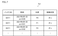
- FIG. 4 is a diagram showing an example of a working machine data table Tb1 stored by the data matching device 10;
- FIG. 4 is a diagram showing an example of a battery management table Tb2 stored by the data matching device 10;
- FIG. 4 is a flowchart showing an example of data matching processing (data matching method) executed by the data matching device 10;
- the movable body in the present invention is a work machine used for a predetermined work such as a lawnmower or a blower.
- IT Information Technology
- work machines are progressing for the purpose of improving work efficiency.
- the operation status of the work equipment will be notified to the operator who operates the work equipment, so that the operator can grasp the work equipment that is not operating or the work equipment with low work efficiency.
- the work machine is a lawn mower
- the operator can be a landscape gardener who undertakes lawn mowing in a predetermined public space (for example, a park).
- a predetermined public space for example, a park.
- operators can, for example, transfer work machines that are not working to other sites to make effective use of the work machines, or improve work efficiency. It is possible to improve work efficiency by replacing a low working machine with another working machine.
- wireless communication using a mobile communication network such as a cellular line (hereinafter also simply referred to as "wireless communication”) is used for communication by the work machine.
- a mobile communication network such as a cellular line
- wireless communication cost is incurred by the operator who operates the work machine (the communication fee may be paid by the work machine manufacturer). In that case, it can be a heavy burden for the work machine manufacturer). Under such circumstances, it is desirable to reduce the amount of communication as much as possible in a work machine that communicates wirelessly.
- the data matching device, the data matching method, and the data matching program of the present embodiment are intended to reduce the amount of communication of work machines that communicate wirelessly while suppressing the deterioration of convenience for users such as operators. enable.
- the data matching system 1 is configured by providing the data matching device 10 of the present embodiment so as to be able to communicate with each of the working machine 20, the charging device 30, and the computer 40 via the network NET.
- Network NET is, for example, the Internet.
- the data matching device 10 is, for example, a server device (computer) managed by a service provider that provides various data to an operator who operates the work machine 20 (hereinafter also simply referred to as an "operator").
- the computer 40 is an example of a predetermined output destination in the present invention, and is a computer of an operator.
- the computer 40 may be a server device managed by the operator, or may be a terminal device (for example, a smart phone, a tablet terminal, a PC, etc.) used by an employee of the operator.
- the computer 40 to which data is output by the data matching device 10 is preset in the data matching device 10 by, for example, a service provider or the like.
- the data matching device 10 may be provided as a part of the computer 40 , and in that case, the output destination of the data by the data matching device 10 may be a display or the like provided in the computer 40 .
- the data matching device 10 may be a server device managed by an operator, and the computer 40 may be a terminal device used by an employee of the operator. Furthermore, the data matching device 10 may be a server device managed by the above service provider, and the computer 40 may be a server device managed by a rental business operator that lends the working machine 20 to the operator.
- the working machine 20 is an example of a moving body in the present invention.
- Work machine 20 is an electric work machine (for example, a lawn mower) which is constructed such that a battery BAT including a secondary battery such as a lithium ion battery can be attached and detached, and which is driven by the attached battery BAT as a power supply.
- battery BAT is removed from work machine 20 and then attached to charging device 30 .
- the charging device 30 is connected to an external power supply (for example, a commercial power supply) and charges the attached battery BAT with the electric power of the external power supply.
- Battery BAT charged by charging device 30 can be reused as a power source for work implement 20 .
- the battery BAT may be owned by the operator, or may be lent to the operator by the service provider.
- the battery BAT is configured to be able to store log data Lg about the usage status of its own device and output the stored log data Lg to the outside of the battery BAT (for example, the charging device 30).
- the battery BAT includes a battery IC (Integrated Circuit) that is a microcontroller that controls the entire battery BAT, a non-volatile storage medium such as a flash memory, and a battery sensor (none of which is shown). ).
- the battery sensor detects the output voltage, charge/discharge current, temperature, etc. of the battery BAT. Based on the detection result of the battery sensor, the battery IC generates log data representing chronological changes in the output voltage of the battery BAT, etc. (for example, substantially continuous changes in increments of 1 second, see FIG. 5) during a predetermined target period. Generate Lg.
- the target period is a period from when the battery BAT is removed from the charging device 30 to when it is attached to the charging device 30 again. That is, the period during which battery BAT is used in work machine 20 is included in the target period, and log data Lg is generated.
- the log data Lg may include information other than the output voltage of the battery BAT.
- the log data Lg may include information representing chronological changes in the temperature of the battery BAT during the target period.
- an acceleration sensor may be provided in the battery BAT so that the log data Lg may include information indicating the number of times the battery BAT is subjected to acceleration (ie impact) exceeding a predetermined value.
- the log data Lg generated by the battery IC is stored in the storage medium of the battery BAT. Then, when battery BAT is attached to charging device 30 , battery IC transmits battery data including log data Lg stored in the storage medium to charging device 30 .
- the battery data is data configured by linking the battery ID for identifying the battery BAT and the log data Lg. Communication between battery BAT and charging device 30 may be performed via a physical terminal or the like, or may be performed by short-range wireless communication.
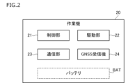
- work machine 20 includes control unit 21 , drive unit 22 , communication unit 23 , and GNSS receiver 24 . Further, as described above, the battery BAT can be attached to the working machine 20, and the battery BAT attached to the working machine 20 is indicated by a broken line in FIG.
- the control unit 21 comprehensively controls the work machine 20 as a whole.
- the control unit 21 is implemented by, for example, an ECU (Electronic Control Unit) including a processor, memory, input/output interface, and the like.
- the drive unit 22 causes the work machine 20 to travel and operates a work unit (not shown) of the work machine 20 (for example, a blade for cutting grass in the case of a lawn mower) under the control of the control unit 21.
- output the power of Drive unit 22 is implemented by, for example, a motor that is driven using the power of battery BAT attached to work machine 20 .
- the communication unit 23 communicates with the outside of the work machine 20 (for example, the data matching device 10) by wireless communication.
- the communication unit 23 is realized by, for example, a TCU (Telematics Control Unit) that can access the network NET by wireless communication.
- the GNSS receiver 24 Based on the signals received from the GNSS satellites, the GNSS receiver 24 identifies the point where the GNSS receiver 24 was located at a certain time (that is, the position of the work implement 20), and transmits information indicating the identification result to the control unit 21.
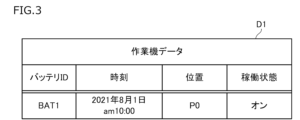
- the control unit 21 Based on the information acquired from the GNSS receiver 24 and the like, the control unit 21 generates work machine data D1 related to the work machine 20 at a predetermined cycle, and transmits the generated work machine data D1 to the communication unit 23 by wireless communication. It is transmitted to the matching device 10 (see also FIG. 1). A period in which work machine 20 (control unit 21) transmits work machine data D1 to data matching device 10 is set in advance. As an example, in the present embodiment, from the viewpoint of reducing the communication by the work machine 20 and ensuring the real-time property of the information contained in the work machine data D1 to the minimum required, the work machine 20 is operated at intervals of one minute (that is, intermittently). ), the work machine data D1 is transmitted to the data matching device 10. FIG.
- the work implement data D1 includes the battery ID of the battery BAT attached to the work implement 20 when the work implement data D1 was generated, the time when the work implement data D1 was generated, and the time when the work implement data D1 was generated. information representing the position and operating state of the working machine 20 in the .
- the operating state of work implement 20 is, for example, whether the main power switch of work implement 20 is on or off.
- the working machine 20 to which the battery BAT with the battery ID "BAT1" is attached is located at the point P0 at the time "August 1, 2021 at 10:00". , and its operating state is on.
- control unit 21 of the work machine 20 can acquire information representing the battery ID of the battery BAT by appropriately communicating with the battery IC of the battery BAT attached to the work machine 20, for example. Communication between battery BAT and working machine 20 may be performed via a physical terminal or the like, or may be performed by short-range wireless communication.
- charging device 30 includes control unit 31 , charging unit 32 , and communication unit 33 . Further, as described above, the battery BAT can be attached to the charging device 30, and in FIG. 4, the battery BAT attached to the charging device 30 is indicated by a dashed line.
- the control unit 31 controls the charging device 30 as a whole.
- the control unit 31 is implemented by, for example, a microcontroller including a processor, memory, input/output interface, and the like.
- Charging unit 32 supplies electric power from an external power supply to battery BAT attached to charging device 30 under the control of control unit 31 .
- the charging unit 32 is implemented by, for example, an electric circuit configured by combining various electronic components.
- the communication unit 33 communicates with the outside of the charging device 30 (for example, the data matching device 10) under the control of the control unit 31.
- the communication unit 33 is realized by, for example, a communication interface that can access the network NET via a fixed line such as an optical line.
- the communication unit 33 may be connected to a fixed line via a wireless or wired LAN (Local Area Network), for example.
- the battery data (hereinafter also referred to as "battery data D2") in which the battery ID and the log data Lg are associated is transmitted to the charging device 30. Then, when the control unit 31 of the charging device 30 receives the battery data D2 transmitted from the battery BAT, the communication unit 33 transmits the battery data D2 to the data matching device 10 (see also FIG. 1).
- the battery data D2 is configured by associating the battery ID with the log data Lg stored in the battery BAT identified by the battery ID.
- the log data Lg is information representing changes in the output voltage of the battery BAT over time during the target period.
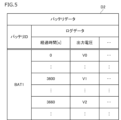
- the battery BAT of this embodiment does not have an RTC (real-time clock) from the viewpoint of cost reduction. Therefore, as shown in FIG. 5, the elapsed time after the battery BAT is removed from the charging device 30 is used as the element representing the time series in the log data Lg.
- the battery data D2 shown in FIG. 5 indicates that the output voltage of the battery BAT when the battery BAT with the battery ID "BAT1" is removed from the charging device 30 (that is, when the elapsed time is 0 [s]) is V0.
- the output voltage of battery BAT is V1
- the output voltage of battery BAT is V1 after battery BAT is removed from charging device 30. It shows that the output voltage of the battery BAT after 1 hour and 1 minute (that is, the elapsed time is 3660 [s]) is V2.
- the control unit 31 of the charging device 30 transmits battery attachment/detachment information indicating that the battery BAT has been attached/detached to the data matching device 10 via the communication unit 33.
- the battery attachment/detachment information includes the battery ID of the battery BAT attached/detached in the charging device 30, the time when the attachment/detachment was performed, and the fact that the battery was attached to the charging device 30 or removed from the charging device 30. , (see, for example, FIG. 8).
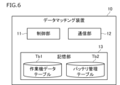
- the data matching device 10 includes a control section 11 , a communication section 12 and a storage section 13 .
- the control unit 11 centrally controls the entire data matching device 10 .
- the control unit 11 is implemented, for example, by executing a program stored in a memory or the like by a processor of a computer that implements the data matching device 10 .
- the communication unit 12 communicates with the outside of the data matching device 10 (for example, the work machine 20, the charging device 30, and the computer 40) under the control of the control unit 11.
- the communication unit 12 is implemented by, for example, a communication interface that can access the network NET.
- the storage unit 13 is implemented by a storage medium such as a memory or hard disk, for example, and stores various types of information including a working machine data table Tb1 and a battery management table Tb2.
- the control unit 11 is configured to be able to acquire work machine data D1 transmitted from the work machine 20 . Specifically, the control unit 11 acquires the work machine data D ⁇ b>1 transmitted from the work machine 20 by receiving the work machine data D ⁇ b>1 through the communication unit 12 . After acquiring the work machine data D1, the control unit 11 stores the acquired work machine data D1 in the work machine data table Tb1.
- FIG. 7 shows an example of the working machine data table Tb1.
- working equipment data table Tb1 illustrated in FIG.
- work machine data D1 transmitted from work machine 20 to which battery BAT with battery ID "BAT1" is attached to data matching device 10 is stored.
- control unit 11 when acquiring the work machine data D1, the control unit 11 outputs the acquired work machine data D1 to the computer 40 .
- the control unit 11 transmits the acquired work machine data D1 to the computer 40 through the communication unit 12 at the timing of acquiring the work machine data D1.
- control unit 11 is configured to be able to acquire battery attachment/detachment information transmitted from the charging device 30 . Specifically, the control unit 11 obtains the battery attachment/detachment information transmitted from the charging device 30 by receiving the battery attachment/detachment information through the communication unit 12 . After acquiring the battery attachment/detachment information, the control unit 11 stores the acquired battery attachment/detachment information in the battery management table Tb2.
- FIG. 8 shows an example of the battery management table Tb2.
- the battery attachment/detachment information indicating that the battery BAT with the battery ID “BAT1” was removed from the charging device 30 at the time “August 1, 2021 at 9:00 am” is stored.
- Battery attachment/detachment information indicating that the battery was attached (in other words, returned) to the charging device 30 at the time “18:00 pm on August 1, 2021” is stored.
- the control unit 11 determines that the battery BAT with the battery ID "BAT1" is changed from "August 1, 2021 am 9:00” to "August 1, 2021 pm 18". : 00”, it can be identified (recognized) that it has been removed from the charging device 30 . In this way, the control unit 11 can specify the target period in which the log data Lg is stored by referring to the battery management table Tb2.
- control unit 11 is configured to be able to acquire the battery data D2 transmitted from the charging device 30 . Specifically, the control unit 11 acquires the battery data D ⁇ b>2 transmitted from the charging device 30 by receiving the battery data D ⁇ b>2 through the communication unit 12 .
- the control unit 11 when acquiring the battery data D2, the control unit 11 generates matched data Dm by linking the acquired working machine data D1 and the battery data D2. Specifically, when the battery data D2 is acquired, the control unit 11 first acquires the work machine data D1 having the same battery ID as the battery ID of the acquired battery data D2 (hereinafter also referred to as "target ID"). Search from the data table Tb1. Hereinafter, among the work machine data D1 stored in the work machine data table Tb1, the work machine data D1 having the same battery ID as the target ID is also referred to as "linking candidate work machine data".
- the control unit 11 searches the working machine data table Tb1 for the working machine data D1 whose battery ID is "BAT1" as the candidate working machine data to be linked.
- the working machine data table Tb1 is as illustrated in FIG. 10:02 a.m. on the 1st of the month”
- the work machine data D1 and the like transmitted from the work machine 20 to which the battery BAT with the battery ID “BAT1” is attached to the data matching device 10 are searched as the candidate work machine data for tying.
- control unit 11 refers to the battery management table Tb2, and determines the period during which the battery BAT with the target ID was removed from the charging device 30 (that is, the target period during which the battery BAT with the target ID stored the log data Lg). Identify.
- the control unit 11 allows the battery BAT with the battery ID “BAT1” to be removed from the charging device 30 from “March 1, 2021 at 9:00 am” to “March 1, 2021 at 18:00 pm”. identified as the period in which it was
- control unit 11 links the working machine data D1 having the information of the time included in the period specified above among the linked candidate working machine data to the acquired battery data D2, thereby obtaining the matched data Dm. to generate
- the period in which the target ID is “BAT1” and the battery BAT with the battery ID “BAT1” was removed from the charging device 30 is from “August 1, 2021 at 9:00 am” to “August 1, 2021”. It is assumed that the period until 18:00 pm is specified. Here, the times of “August 1, 2021 am 10:00”, “August 1, 2021 am 10:01”, and “August 1, 2021 am 10:02” are included in the specified period. It will be the time when Therefore, in this case, for example, if the working machine data table Tb1 is as illustrated in FIG. Aug. 1, 2002 am 10:02", the work machine data D1 and the like transmitted from the work machine 20 to which the battery BAT with the battery ID "BAT1" is attached to the data matching device 10 are linked to the battery data D2. are added to generate matched data Dm.
- the control unit 11 determines at what time each output voltage, etc., represented by the log data Lg. It can be determined whether they are compatible. Therefore, in generating the matched data Dm, the control unit 11 can associate the output voltage or the like at a certain time represented by the log data Lg with the working machine data D1 at that time. Specifically, for example, the control unit 11 adds a work machine whose time is “August 1, 2021 at 10:00 am” to a location corresponding to “August 1, 2021 am 10:00” represented by the log data Lg. Data D1 may be linked. As a result, it is possible to generate the matched data Dm in which the work machine data D1 and the battery data D2 are linked more finely in time series.
- the control unit 11 After generating the matched data Dm in this manner, the control unit 11 outputs the generated matched data Dm to the computer 40 (see also FIG. 1).
- the data matching device 10 can provide the operator with the matched data Dm in which the work machine data D1 related to the work machine 20 and the battery data D2 related to the battery BAT used in the work machine 20 are linked. Therefore, even if the communication amount of the work machine 20 is reduced, the operator can obtain the matched data Dm necessary for grasping the work efficiency of the work machine 20 or the like.
- the data matching device 10 determines whether or not battery attachment/detachment information has been received from the charging device 30 (step S01). When the data matching device 10 determines that the battery attachment/detachment information has not been received (step S01: NO), the data matching device 10 directly proceeds to the process of step S03. On the other hand, when the data matching device 10 determines that the battery attachment/detachment information has been received (step S01: YES), the data matching device 10 stores the received battery attachment/detachment information in the battery management table Tb2 (step S02), and proceeds to the process of step S03. Transition.
- the data matching device 10 determines whether or not the working machine data D1 has been received from the working machine 20 (step S03).
- step S03: NO the data matching device 10 directly proceeds to the processing of step S05.
- step S03: YES data matching device 10 stores received working machine data D1 in working machine data table Tb1 and transmits it to computer 40 ( Step S04), the process proceeds to step S05.
- the data matching device 10 determines whether or not the battery data D2 has been received from the charging device 30 (step S05). Then, when the data matching device 10 determines that the battery data D2 has not been received (step S05: NO), the series of processes shown in FIG. 9 ends.
- the data matching device 10 determines that the battery data D2 has been received (step S05: YES), it searches the work machine data table Tb1 for tie candidate work machine data (step S06).
- the candidate work machine data to be linked is the same as the battery ID (that is, the target ID) of the acquired (received) battery data D2 in the work machine data D1 stored in the work machine data table Tb1.
- the data matching device 10 determines whether or not the linking candidate work machine data has been retrieved (step S07). Then, when the data matching device 10 determines that the linking candidate work machine data has not been retrieved (step S07: NO), the series of processes shown in FIG. 9 ends. On the other hand, when the data matching device 10 determines that the linking candidate work machine data has been retrieved (step S07: YES), the battery BAT with the target ID is removed from the charging device 30 by referring to the battery management table Tb2. (ie, the target period during which the battery BAT with the target ID stored the log data Lg) is specified (step S08).
- the data matching device 10 searches for data having time information included in the period specified by the process of step S08 from among the tying candidate work machine data (step S09). Then, the data matching device 10 determines whether or not the corresponding working machine data D1 has been retrieved by the process of step S09 (step S10).
- step S10 NO
- step S10: YES the data matching device 10 matches all the working machine data D1 searched by the process of step S09 to the received battery data.
- step S11 the series of processes shown in FIG. 9 is terminated.
- the data matching device 10 generates the matched data Dm and transmits it to the computer 40 at the timing when the data matching device 10 receives the battery data D2, but the present invention is not limited to this.
- data matching device 10 after receiving battery data D2, in response to a request for output of matched data Dm from computer 40, data matching device 10 generates matched data Dm and transmits it to computer 40. good too. In this way, it becomes possible to provide the matched data Dm at the timing desired by the user such as the operator.
- the data matching device 10 terminates the series of processes shown in FIG. 9 as it is when no tying candidate work machine data is found, but the present invention is not limited to this.
- the data matching device 10 is detached from the target charging device 30 (the charging device 30 for charging the battery BAT used in the work machine 20). Error information may be sent to the computer 40 suggesting that it may not be the battery BAT. With this error information, for example, it is possible to suppress the mixture of the target battery BAT to be charged by the target charging device 30 and the non-target battery (for other than the working machine 20).
- the data matching device 10 may also transmit predetermined error information to the computer 40 when it is determined that the relevant work machine data D1 has not been retrieved.
- the data matching device 10 includes the work machine data D1 related to the work machine 20 that is transmitted from the work machine 20 that wirelessly communicates with the work machine data D1 that is transmitted from the charging device 30 that charges the battery BAT used in the work machine 20 . and battery data D2 relating to the battery BAT. Then, when acquiring the working machine data D1 and the battery data D2, the data matching device 10 generates matched data Dm in which the acquired working machine data D1 and the battery data D2 are linked, and generates matched data Dm. Dm is output to computer 40 . As a result, compared to the case where work machine 20 transmits work machine data D ⁇ b>1 and battery data D ⁇ b>2 to computer 40 , the communication amount of work machine 20 can be reduced. Even if the amount of communication of the working machine 20 is reduced in this way, it is possible to provide the user such as the operating company with the matched data Dm in which the working machine data D1 and the battery data D2 are linked. You can suppress the decline.
- the battery BAT is configured to be capable of storing log data Lg regarding the usage status of the battery BAT and outputting the stored log data Lg to the charging device 30 .
- Battery data D ⁇ b>2 transmitted from charging device 30 to data matching device 10 includes log data Lg output from battery BAT to charging device 30 .
- data matching device 10 can generate matched data Dm including log data Lg about the usage status of battery BAT used in work implement 20 .
- the work machine data D1 also includes information representing the position and operating state of the work machine 20 at a predetermined time.
- the data matching device 10 can generate matched data Dm including information representing the position and operating state of the work implement 20 at a predetermined time.
- the working machine data D1 includes information representing the position and operating state of the working machine 20, but the present invention is not limited to this.
- Work implement data D ⁇ b>1 may include only one of information on the position and operating state of work implement 20 . If work implement data D1 includes only one of information on the position and operating state of work implement 20, the amount of communication of work implement 20 can be further reduced. For example, if it is known in advance that the work machine 20 works only at a specific work site, the information representing the position of the work machine 20 (that is, the location of the work site) is sent to the data matching device 10 or the computer 40. can be stored in advance.
- the work implement data D1 does not include information representing the position of the work implement 20
- the work machine data D1 and the battery data D2 include a battery ID that is identification information for identifying the battery BAT, and the data matching device 10 associates the work machine data D1 and the battery data D2 that include the same battery ID. generated matched data Dm.
- the data matching device 10 appropriately matches the work machine data D1 regarding the work machine 20 and the battery data D2 regarding the battery BAT used in the work machine 20. can generate matched data Dm associated with .
- the matched data Dm is generated by linking the work machine data D1 and the battery data D2 including the same battery ID, but the present invention is not limited to this.
- a work machine ID that identifies the work machine 20 may be used instead of the battery ID in the present embodiment.
- work machine 20 transmits work machine data D ⁇ b>1 including the work machine ID of its own device to data matching device 10 . Further, the work machine 20 notifies the battery BAT (battery IC) attached thereto of the work machine ID of its own device.
- the battery BAT transmits battery data D2 in which the work machine ID and the log data Lg are linked to the charging device 30 , and the charging device 30 transmits the battery data D2 to the data matching device 10 .
- This enables the data matching device 10 to generate the matched data Dm in which the work machine data D1 and the battery data D2 including the same work machine ID are linked.
- both the battery ID and the work machine ID are included in each of the work machine data D1 and the battery data D2, so that the data matching device 10 can match the work machine data D1 and the work machine data D1 and the work machine data D2 including the same battery ID and work machine ID.
- the matched data Dm linked with the battery data D2 may be generated.
- the battery data D2 includes log data Lg regarding the usage status of the battery BAT during the target period from when the battery BAT is removed from the charging device 30 to when it is reattached to the charging device 30 .
- the data matching device 10 generates matched data Dm by linking the working machine data D1 corresponding to the time included in the target period in which the log data Lg of the acquired battery data D2 is stored to the acquired battery data D2. Generate.
- the data matching device 10 can generate the matched data Dm in which the work machine data D1 and the battery data D2 that are appropriate in time series are linked.
- the charging apparatus 30 transmits to the data matching apparatus 10 battery attachment/detachment information indicating that the battery BAT has been attached/detached. Based on the battery attachment/detachment information transmitted from the charging device 30, the data matching device 10 identifies the target period in which the log data Lg is stored. As a result, the data matching device 10 associates the appropriate working machine data D1 and the battery data D2 chronologically, even if the log data Lg does not contain information about the time when the log data Lg was stored. matched data Dm can be generated. Therefore, the RTC and the like can be omitted from the battery BAT, and the configuration of the battery BAT can be simplified.
- the data matching device 10 outputs the acquired work machine data D1 to the computer 40 when only the work machine data D1 out of the work machine data D1 and the battery data D2 is acquired.
- the data matching device 10 can quickly output the work machine data D1 including information in which real-time performance is emphasized to the computer 40, and the delay in transmission of this information reduces convenience for users such as operators. can be avoided.
- the data matching device 10 outputs the working machine data D1 to the computer 40 at the timing of acquiring the working machine data D1.
- the data matching device 10 can quickly output the work machine data D1 including information in which real-time performance is emphasized to the computer 40, and the delay in transmission of this information reduces convenience for users such as operators. can be avoided.
- the data matching device 10 acquires the battery data D2 after outputting the working machine data D1 to the computer 40
- the data matching device 10 outputs to the computer 40 matched data Dm in which the working machine data D1 and the battery data D2 are linked. Accordingly, when the battery data D2 is acquired after the work machine data D1 is output, the matched data Dm can be provided to the user such as the operator.
- the present invention is not limited to the above-described embodiments, and can be modified, improved, etc. as appropriate.
- a lawnmower or the like is used as a working machine, which is an example of a mobile body in the present invention.
- the moving body in the present invention is not limited to such a work machine. That is, the mobile object may be any object as long as it is capable of wireless communication and is driven by the electric power of a predetermined battery such as the battery BAT in the above-described embodiment. ), robots, ships, aircraft, and the like.
- a charging device (A data matching device (data matching device 10) configured to be able to acquire second data (battery data D2) transmitted from a charging device 30) and related to the battery, generating matched data (matched data Dm) in which the first data and the second data are linked when the first data and the second data are acquired; outputting the generated matched data to a predetermined output destination; Data matching device.
- the mobile unit transmits the first data and the second data. Even if the communication amount of the mobile unit is reduced in this way, the matched data in which the first data and the second data are linked can be output to a predetermined output destination, so that the user's convenience is not deteriorated. can be suppressed.
- the battery is configured to store log data (log data Lg) about the usage status of the battery and output the stored log data to the charging device, wherein the second data includes the log data output from the battery to the charging device; Data matching device.
- log data Lg log data Lg
- the data matching device includes information representing the position and/or operating state of the mobile object at a predetermined time, Data matching device.
- the data matching device according to any one of (1) to (3), the first data and the second data include identification information for identifying the battery and/or the mobile body; The data matching device generates the matched data by linking the first data and the second data containing the same identification information. Data matching device.
- the data matching device stores log data on the usage status of the battery for a target period from when the battery is removed from the charging device to when the battery is reattached to the charging device, and the stored log data is stored in the charging device.
- the second data includes the log data output from the battery to the charging device;
- the first data includes information representing the position and/or operating state of the mobile object at a predetermined time;
- the data matching device generates the matched data in which the first data corresponding to the time included in the target period in which the log data of the acquired second data is stored is linked to the second data. do, Data matching device.
- the charging device further transmits battery attachment/detachment information indicating that the battery has been attached/detached to the data matching device when the battery is attached/detached in the charging device,
- the data matching device identifies the target period based on the battery attachment/detachment information. Data matching device.
- the matched data in which the first data and the second data are chronologically appropriate is generated. can be generated.
- the first data regarding the work machine may include information in which real-time performance is emphasized. According to (7), it is possible to quickly output the first data, which may include information for which real-time performance is important, and to avoid a decrease in convenience for the user due to a delay in transmission of this information.
- the first data is output to a predetermined output destination at the timing when the first data is obtained. This makes it possible to quickly output the first data, which may include information for which real-time performance is important, and avoid a decrease in convenience for the user due to a delay in transmission of this information. Then, when the second data is acquired after the output of the first data, the matched data in which the first data and the second data are linked is output to a predetermined output destination. Accordingly, when the second data is obtained after the first data is output, the matched data can be provided to the user.
- (10) Acquiring first data relating to the mobile body transmitted from a mobile body communicating wirelessly and second data relating to the battery transmitted from a charging device for charging the battery used in the mobile body.
- a computer configured to allow when the first data and the second data are acquired, generating matched data in which the acquired first data and the second data are linked; outputting the generated matched data to a predetermined output destination;
- a data matching program that executes processing.
Landscapes
- Engineering & Computer Science (AREA)
- Power Engineering (AREA)
- Transportation (AREA)
- Mechanical Engineering (AREA)
- Theoretical Computer Science (AREA)
- Computational Linguistics (AREA)
- Data Mining & Analysis (AREA)
- Databases & Information Systems (AREA)
- Physics & Mathematics (AREA)
- General Engineering & Computer Science (AREA)
- General Physics & Mathematics (AREA)
- Charge And Discharge Circuits For Batteries Or The Like (AREA)
Abstract
Description
無線通信する移動体から送信され且つ前記移動体に関する第1データと、前記移動体で使用されたバッテリを充電する充電装置から送信され且つ前記バッテリに関する第2データと、のそれぞれを取得可能に構成されたデータマッチング装置であって、
前記第1データおよび前記第2データを取得した場合に、取得した前記第1データと前記第2データとを紐付けたマッチング済データを生成し、
生成した前記マッチング済データを所定の出力先へ出力する、
データマッチング装置である。
無線通信する移動体から送信され且つ前記移動体に関する第1データと、前記移動体で使用されたバッテリを充電する充電装置から送信され且つ前記バッテリに関する第2データと、のそれぞれを取得可能に構成されたコンピュータが、
前記第1データおよび前記第2データを取得した場合に、取得した前記第1データと前記第2データとを紐付けたマッチング済データを生成し、
生成した前記マッチング済データを所定の出力先へ出力する、
処理を実行する、データマッチング方法である。
無線通信する移動体から送信され且つ前記移動体に関する第1データと、前記移動体で使用されたバッテリを充電する充電装置から送信され且つ前記バッテリに関する第2データと、のそれぞれを取得可能に構成されたコンピュータに、
前記第1データおよび前記第2データを取得した場合に、取得した前記第1データと前記第2データとを紐付けたマッチング済データを生成し、
生成した前記マッチング済データを所定の出力先へ出力する、
処理を実行させる、データマッチングプログラムである。
まず、本実施形態のデータマッチング装置を適用したデータマッチングシステムについて説明する。図1に示すように、データマッチングシステム1は、本実施形態のデータマッチング装置10を、作業機20、充電装置30、およびコンピュータ40のそれぞれとネットワークNETを介して通信可能に設けて構成される。ネットワークNETは、例えばインターネットである。
次に、作業機20について具体的に説明する。図2に示すように、作業機20は、制御部21と、駆動部22と、通信部23と、GNSS受信機24とを備える。また、前述したように、作業機20にはバッテリBATを装着可能であり、図2では、作業機20に装着されたバッテリBATを破線であらわしている。
ここで、作業機データD1の一例について説明する。図3に示すように、作業機データD1は、当該作業機データD1の生成時において作業機20に装着されたバッテリBATのバッテリIDと、当該作業機データD1の生成時の時刻と、その時刻における作業機20の位置および稼働状態とをあらわす情報を紐付けて構成される。作業機20の稼働状態とは、例えば、作業機20のメイン電源スイッチがオンであるかオフであるかである。
次に、充電装置30について具体的に説明する。図4に示すように、充電装置30は、制御部31と、充電部32と、通信部33とを備える。また、前述したように、充電装置30にはバッテリBATを装着可能であり、図4では、充電装置30に装着されたバッテリBATを破線であらわしている。
ここで、バッテリデータD2の一例について説明する。図5に示すように、バッテリデータD2は、バッテリIDと、当該バッテリIDによって識別されるバッテリBATで記憶されたログデータLgとを紐付けて構成される。
次に、データマッチング装置10について具体的に説明する。図6に示すように、データマッチング装置10は、制御部11と、通信部12と、記憶部13とを備える。制御部11は、データマッチング装置10全体を統括制御する。制御部11は、例えば、データマッチング装置10を実現するコンピュータのプロセッサがメモリ等に記憶されたプログラムを実行することにより実現される。
次に、図9を参照して、データマッチング装置10が実行するデータマッチング処理(データマッチング方法)の一例について説明する。データマッチング装置10は、例えば、図9に示すデータマッチング処理を所定の周期で繰り返し実行する。なお、このデータマッチング処理をデータマッチング装置10に実行させるデータマッチングプログラムは、データマッチング装置10の記憶媒体等(例えば記憶部13)にあらかじめ記憶されている。
前記第1データおよび前記第2データを取得した場合に、取得した前記第1データと前記第2データとを紐付けたマッチング済データ(マッチング済データDm)を生成し、
生成した前記マッチング済データを所定の出力先へ出力する、
データマッチング装置。
前記バッテリは、前記バッテリの使用状況についてのログデータ(ログデータLg)を記憶し、記憶した前記ログデータを前記充電装置へ出力可能に構成され、
前記第2データは、前記バッテリから前記充電装置へ出力された前記ログデータを含む、
データマッチング装置。
前記第1データは、所定の時刻における前記移動体の位置および/または稼働状態をあらわす情報を含む、
データマッチング装置。
前記第1データおよび前記第2データは、前記バッテリおよび/または前記移動体を識別する識別情報を含み、
前記データマッチング装置は、同一の前記識別情報を含む前記第1データと前記第2データとを紐付けた前記マッチング済データを生成する、
データマッチング装置。
前記バッテリは、前記バッテリが前記充電装置から取り外されてから前記充電装置に再度装着されるまでの対象期間における、前記バッテリの使用状況についてのログデータを記憶し、記憶した前記ログデータを前記充電装置へ出力可能に構成され、
前記第2データは、前記バッテリから前記充電装置へ出力された前記ログデータを含み、
前記第1データは、所定の時刻における前記移動体の位置および/または稼働状態をあらわす情報を含み、
前記データマッチング装置は、取得した前記第2データの前記ログデータが記憶された前記対象期間に含まれる時刻に対応する前記第1データを、前記第2データに紐付けた前記マッチング済データを生成する、
データマッチング装置。
前記充電装置は、さらに、前記充電装置において前記バッテリの着脱が行われると、前記バッテリの着脱が行われたことをあらわすバッテリ着脱情報を前記データマッチング装置へ送信し、
前記データマッチング装置は、前記バッテリ着脱情報に基づいて、前記対象期間を特定する、
データマッチング装置。
前記第1データおよび前記第2データのうち前記第1データのみを取得した場合に、取得した前記第1データを前記出力先へ出力する、
データマッチング装置。
前記第1データを取得したタイミングで、取得した前記第1データを前記出力先へ出力し、
前記第1データを前記出力先へ出力した後に前記第2データを取得すると、前記第1データと前記第2データとを紐付けた前記マッチング済データを前記出力先へ出力する、
データマッチング装置。
前記第1データおよび前記第2データを取得した場合に、取得した前記第1データと前記第2データとを紐付けたマッチング済データを生成し、
生成した前記マッチング済データを所定の出力先へ出力する、
処理を実行する、データマッチング方法。
前記第1データおよび前記第2データを取得した場合に、取得した前記第1データと前記第2データとを紐付けたマッチング済データを生成し、
生成した前記マッチング済データを所定の出力先へ出力する、
処理を実行させる、データマッチングプログラム。
10 データマッチング装置
20 作業機(移動体)
30 充電装置
BAT バッテリ
D1 作業機データ(第1データ)
D2 バッテリデータ(第2データ)
Dm マッチング済データ
Lg ログデータ
Claims (10)
- 無線通信する移動体から送信され且つ前記移動体に関する第1データと、前記移動体で使用されたバッテリを充電する充電装置から送信され且つ前記バッテリに関する第2データと、のそれぞれを取得可能に構成されたデータマッチング装置であって、
前記第1データおよび前記第2データを取得した場合に、取得した前記第1データと前記第2データとを紐付けたマッチング済データを生成し、
生成した前記マッチング済データを所定の出力先へ出力する、
データマッチング装置。 - 請求項1に記載のデータマッチング装置であって、
前記バッテリは、前記バッテリの使用状況についてのログデータを記憶し、記憶した前記ログデータを前記充電装置へ出力可能に構成され、
前記第2データは、前記バッテリから前記充電装置へ出力された前記ログデータを含む、
データマッチング装置。 - 請求項1または2に記載のデータマッチング装置であって、
前記第1データは、所定の時刻における前記移動体の位置および/または稼働状態をあらわす情報を含む、
データマッチング装置。 - 請求項1から3のいずれか1項に記載のデータマッチング装置であって、
前記第1データおよび前記第2データは、前記バッテリおよび/または前記移動体を識別する識別情報を含み、
前記データマッチング装置は、同一の前記識別情報を含む前記第1データと前記第2データとを紐付けた前記マッチング済データを生成する、
データマッチング装置。 - 請求項1から4のいずれか1項に記載のデータマッチング装置であって、
前記バッテリは、前記バッテリが前記充電装置から取り外されてから前記充電装置に再度装着されるまでの対象期間における、前記バッテリの使用状況についてのログデータを記憶し、記憶した前記ログデータを前記充電装置へ出力可能に構成され、
前記第2データは、前記バッテリから前記充電装置へ出力された前記ログデータを含み、
前記第1データは、所定の時刻における前記移動体の位置および/または稼働状態をあらわす情報を含み、
前記データマッチング装置は、取得した前記第2データの前記ログデータが記憶された前記対象期間に含まれる時刻に対応する前記第1データを、前記第2データに紐付けた前記マッチング済データを生成する、
データマッチング装置。 - 請求項5に記載のデータマッチング装置であって、
前記充電装置は、さらに、前記充電装置において前記バッテリの着脱が行われると、前記バッテリの着脱が行われたことをあらわすバッテリ着脱情報を前記データマッチング装置へ送信し、
前記データマッチング装置は、前記バッテリ着脱情報に基づいて、前記対象期間を特定する、
データマッチング装置。 - 請求項1から6のいずれか1項に記載のデータマッチング装置であって、
前記第1データおよび前記第2データのうち前記第1データのみを取得した場合に、取得した前記第1データを前記出力先へ出力する、
データマッチング装置。 - 請求項1から7のいずれか1項に記載のデータマッチング装置であって、
前記第1データを取得したタイミングで、取得した前記第1データを前記出力先へ出力し、
前記第1データを前記出力先へ出力した後に前記第2データを取得すると、前記第1データと前記第2データとを紐付けた前記マッチング済データを前記出力先へ出力する、
データマッチング装置。 - 無線通信する移動体から送信され且つ前記移動体に関する第1データと、前記移動体で使用されたバッテリを充電する充電装置から送信され且つ前記バッテリに関する第2データと、のそれぞれを取得可能に構成されたコンピュータが、
前記第1データおよび前記第2データを取得した場合に、取得した前記第1データと前記第2データとを紐付けたマッチング済データを生成し、
生成した前記マッチング済データを所定の出力先へ出力する、
処理を実行する、データマッチング方法。 - 無線通信する移動体から送信され且つ前記移動体に関する第1データと、前記移動体で使用されたバッテリを充電する充電装置から送信され且つ前記バッテリに関する第2データと、のそれぞれを取得可能に構成されたコンピュータに、
前記第1データおよび前記第2データを取得した場合に、取得した前記第1データと前記第2データとを紐付けたマッチング済データを生成し、
生成した前記マッチング済データを所定の出力先へ出力する、
処理を実行させる、データマッチングプログラム。
Priority Applications (4)
| Application Number | Priority Date | Filing Date | Title |
|---|---|---|---|
| PCT/JP2021/043627 WO2023095331A1 (ja) | 2021-11-29 | 2021-11-29 | データマッチング装置、データマッチング方法、およびデータマッチングプログラム |
| JP2023563479A JP7792434B2 (ja) | 2021-11-29 | 2021-11-29 | データマッチング装置、データマッチング方法、データマッチングプログラム、および記憶媒体 |
| US18/713,714 US20250028726A1 (en) | 2021-11-29 | 2021-11-29 | Data matching device, data matching method, and data matching program |
| DE112021008486.0T DE112021008486T5 (de) | 2021-11-29 | 2021-11-29 | Datenabgleichvorrichtung, Datenabgleichverfahren und Datenabgleichprogramm |
Applications Claiming Priority (1)
| Application Number | Priority Date | Filing Date | Title |
|---|---|---|---|
| PCT/JP2021/043627 WO2023095331A1 (ja) | 2021-11-29 | 2021-11-29 | データマッチング装置、データマッチング方法、およびデータマッチングプログラム |
Publications (1)
| Publication Number | Publication Date |
|---|---|
| WO2023095331A1 true WO2023095331A1 (ja) | 2023-06-01 |
Family
ID=86539032
Family Applications (1)
| Application Number | Title | Priority Date | Filing Date |
|---|---|---|---|
| PCT/JP2021/043627 Ceased WO2023095331A1 (ja) | 2021-11-29 | 2021-11-29 | データマッチング装置、データマッチング方法、およびデータマッチングプログラム |
Country Status (4)
| Country | Link |
|---|---|
| US (1) | US20250028726A1 (ja) |
| JP (1) | JP7792434B2 (ja) |
| DE (1) | DE112021008486T5 (ja) |
| WO (1) | WO2023095331A1 (ja) |
Citations (3)
| Publication number | Priority date | Publication date | Assignee | Title |
|---|---|---|---|---|
| WO2020027196A1 (ja) * | 2018-07-31 | 2020-02-06 | 本田技研工業株式会社 | サーバ装置、バッテリ共同利用サービスシステム、方法、コンピュータプログラム及び記憶媒体 |
| WO2020027203A1 (ja) * | 2018-07-31 | 2020-02-06 | 本田技研工業株式会社 | 推定システム、推定装置、推定方法、プログラム、及び記憶媒体 |
| WO2020171170A1 (ja) * | 2019-02-20 | 2020-08-27 | 本田技研工業株式会社 | 情報処理装置、情報処理方法、サービスシステム、プログラム、及び記憶媒体 |
Family Cites Families (1)
| Publication number | Priority date | Publication date | Assignee | Title |
|---|---|---|---|---|
| WO2014103804A1 (ja) | 2012-12-25 | 2014-07-03 | 日本電信電話株式会社 | 光無線アクセスシステム |
-
2021
- 2021-11-29 DE DE112021008486.0T patent/DE112021008486T5/de active Pending
- 2021-11-29 WO PCT/JP2021/043627 patent/WO2023095331A1/ja not_active Ceased
- 2021-11-29 JP JP2023563479A patent/JP7792434B2/ja active Active
- 2021-11-29 US US18/713,714 patent/US20250028726A1/en active Pending
Patent Citations (3)
| Publication number | Priority date | Publication date | Assignee | Title |
|---|---|---|---|---|
| WO2020027196A1 (ja) * | 2018-07-31 | 2020-02-06 | 本田技研工業株式会社 | サーバ装置、バッテリ共同利用サービスシステム、方法、コンピュータプログラム及び記憶媒体 |
| WO2020027203A1 (ja) * | 2018-07-31 | 2020-02-06 | 本田技研工業株式会社 | 推定システム、推定装置、推定方法、プログラム、及び記憶媒体 |
| WO2020171170A1 (ja) * | 2019-02-20 | 2020-08-27 | 本田技研工業株式会社 | 情報処理装置、情報処理方法、サービスシステム、プログラム、及び記憶媒体 |
Also Published As
| Publication number | Publication date |
|---|---|
| JPWO2023095331A1 (ja) | 2023-06-01 |
| DE112021008486T5 (de) | 2024-12-05 |
| JP7792434B2 (ja) | 2025-12-25 |
| US20250028726A1 (en) | 2025-01-23 |
Similar Documents
| Publication | Publication Date | Title |
|---|---|---|
| US11029941B2 (en) | Electrical device and program update method thereof | |
| EP1237328B1 (en) | Link manager and link management method | |
| CN102547646B (zh) | 操作计算设备的方法和系统 | |
| US20210146794A1 (en) | Charging method, apparatus, device, medium, battery management system and charging pile | |
| US6771491B2 (en) | Battery pack | |
| CN102547647B (zh) | 支持知晓成本的应用的操作系统 | |
| CN112181120B (zh) | 服务器设备、机器、电池设备和管理电池设备使用的方法 | |
| US20110160961A1 (en) | Guidance using a worked edge for wayline generation | |
| CN115280804B (zh) | 通过网状网络的设备管理 | |
| CN107144287B (zh) | 一种电动车的出行规划方法和装置 | |
| US9813110B2 (en) | Data transmission using an electrical machine | |
| CN110362598B (zh) | 数据查询的方法、装置、存储介质及电子设备 | |
| CN114328502A (zh) | 一种数据收集方法、装置、网络设备和存储介质 | |
| CN104519262A (zh) | 获取视频数据的方法、装置及终端 | |
| WO2020031396A1 (ja) | 工具、通信装置、工具システム及び通信方法 | |
| WO2023095331A1 (ja) | データマッチング装置、データマッチング方法、およびデータマッチングプログラム | |
| US11245269B2 (en) | Method for obtaining information for operating an accumulator, method for obtaining periods of time for charging different accumulators, and electric gardening and/or forestry apparatus system | |
| RU2012108894A (ru) | Способ предоставления локализованных информационных услуг | |
| US9615332B2 (en) | Mobile terminal device and method for device network setting | |
| WO2023039150A1 (en) | Devices and methods for location-dependent prioritized communication | |
| CN110535919A (zh) | 集中器的入网方法及装置、电力调峰系统 | |
| WO2020021728A1 (ja) | 電動工具及び通信装置 | |
| CN116679697B (zh) | 一种割草机控制方法、割草机系统及割草机 | |
| CN203894415U (zh) | 北斗移动终端的电磁兼容控制设备 | |
| JP2002056898A (ja) | 電池電源装置の交換回収システム |
Legal Events
| Date | Code | Title | Description |
|---|---|---|---|
| 121 | Ep: the epo has been informed by wipo that ep was designated in this application |
Ref document number: 21965700 Country of ref document: EP Kind code of ref document: A1 |
|
| ENP | Entry into the national phase |
Ref document number: 2023563479 Country of ref document: JP Kind code of ref document: A |
|
| WWE | Wipo information: entry into national phase |
Ref document number: 18713714 Country of ref document: US |
|
| WWE | Wipo information: entry into national phase |
Ref document number: 202447048555 Country of ref document: IN |
|
| WWE | Wipo information: entry into national phase |
Ref document number: 112021008486 Country of ref document: DE |
|
| 122 | Ep: pct application non-entry in european phase |
Ref document number: 21965700 Country of ref document: EP Kind code of ref document: A1 |