WO2023095366A1 - Dispositif de vibration et dispositif d'imagerie - Google Patents
Dispositif de vibration et dispositif d'imagerie Download PDFInfo
- Publication number
- WO2023095366A1 WO2023095366A1 PCT/JP2022/022360 JP2022022360W WO2023095366A1 WO 2023095366 A1 WO2023095366 A1 WO 2023095366A1 JP 2022022360 W JP2022022360 W JP 2022022360W WO 2023095366 A1 WO2023095366 A1 WO 2023095366A1
- Authority
- WO
- WIPO (PCT)
- Prior art keywords
- vibrating
- vibration
- extending portion
- vibrating body
- weight
- Prior art date
- Legal status (The legal status is an assumption and is not a legal conclusion. Google has not performed a legal analysis and makes no representation as to the accuracy of the status listed.)
- Ceased
Links
Images












Classifications
-
- H—ELECTRICITY
- H04—ELECTRIC COMMUNICATION TECHNIQUE
- H04N—PICTORIAL COMMUNICATION, e.g. TELEVISION
- H04N23/00—Cameras or camera modules comprising electronic image sensors; Control thereof
- H04N23/80—Camera processing pipelines; Components thereof
- H04N23/81—Camera processing pipelines; Components thereof for suppressing or minimising disturbance in the image signal generation
-
- B—PERFORMING OPERATIONS; TRANSPORTING
- B06—GENERATING OR TRANSMITTING MECHANICAL VIBRATIONS IN GENERAL
- B06B—METHODS OR APPARATUS FOR GENERATING OR TRANSMITTING MECHANICAL VIBRATIONS OF INFRASONIC, SONIC, OR ULTRASONIC FREQUENCY, e.g. FOR PERFORMING MECHANICAL WORK IN GENERAL
- B06B1/00—Methods or apparatus for generating mechanical vibrations of infrasonic, sonic, or ultrasonic frequency
- B06B1/02—Methods or apparatus for generating mechanical vibrations of infrasonic, sonic, or ultrasonic frequency making use of electrical energy
- B06B1/06—Methods or apparatus for generating mechanical vibrations of infrasonic, sonic, or ultrasonic frequency making use of electrical energy operating with piezoelectric effect or with electrostriction
-
- G—PHYSICS
- G02—OPTICS
- G02B—OPTICAL ELEMENTS, SYSTEMS OR APPARATUS
- G02B7/00—Mountings, adjusting means, or light-tight connections, for optical elements
- G02B7/02—Mountings, adjusting means, or light-tight connections, for optical elements for lenses
-
- G—PHYSICS
- G03—PHOTOGRAPHY; CINEMATOGRAPHY; ANALOGOUS TECHNIQUES USING WAVES OTHER THAN OPTICAL WAVES; ELECTROGRAPHY; HOLOGRAPHY
- G03B—APPARATUS OR ARRANGEMENTS FOR TAKING PHOTOGRAPHS OR FOR PROJECTING OR VIEWING THEM; APPARATUS OR ARRANGEMENTS EMPLOYING ANALOGOUS TECHNIQUES USING WAVES OTHER THAN OPTICAL WAVES; ACCESSORIES THEREFOR
- G03B15/00—Special procedures for taking photographs; Apparatus therefor
-
- G—PHYSICS
- G03—PHOTOGRAPHY; CINEMATOGRAPHY; ANALOGOUS TECHNIQUES USING WAVES OTHER THAN OPTICAL WAVES; ELECTROGRAPHY; HOLOGRAPHY
- G03B—APPARATUS OR ARRANGEMENTS FOR TAKING PHOTOGRAPHS OR FOR PROJECTING OR VIEWING THEM; APPARATUS OR ARRANGEMENTS EMPLOYING ANALOGOUS TECHNIQUES USING WAVES OTHER THAN OPTICAL WAVES; ACCESSORIES THEREFOR
- G03B17/00—Details of cameras or camera bodies; Accessories therefor
- G03B17/02—Bodies
-
- G—PHYSICS
- G03—PHOTOGRAPHY; CINEMATOGRAPHY; ANALOGOUS TECHNIQUES USING WAVES OTHER THAN OPTICAL WAVES; ELECTROGRAPHY; HOLOGRAPHY
- G03B—APPARATUS OR ARRANGEMENTS FOR TAKING PHOTOGRAPHS OR FOR PROJECTING OR VIEWING THEM; APPARATUS OR ARRANGEMENTS EMPLOYING ANALOGOUS TECHNIQUES USING WAVES OTHER THAN OPTICAL WAVES; ACCESSORIES THEREFOR
- G03B30/00—Camera modules comprising integrated lens units and imaging units, specially adapted for being embedded in other devices, e.g. mobile phones or vehicles
-
- H—ELECTRICITY
- H04—ELECTRIC COMMUNICATION TECHNIQUE
- H04N—PICTORIAL COMMUNICATION, e.g. TELEVISION
- H04N23/00—Cameras or camera modules comprising electronic image sensors; Control thereof
- H04N23/50—Constructional details
- H04N23/51—Housings
-
- H—ELECTRICITY
- H04—ELECTRIC COMMUNICATION TECHNIQUE
- H04N—PICTORIAL COMMUNICATION, e.g. TELEVISION
- H04N23/00—Cameras or camera modules comprising electronic image sensors; Control thereof
- H04N23/50—Constructional details
- H04N23/52—Elements optimising image sensor operation, e.g. for electromagnetic interference [EMI] protection or temperature control by heat transfer or cooling elements
Definitions
- the present invention relates to a vibrating device and an imaging device.
- a droplet removal device that removes droplets and the like adhering to the luminous flux passage area of the drip-proof cover.
- Patent Literature 1 discloses a liquid droplet ejection device that includes a vibrating member that is connected to the end of the curved surface that forms the dome portion of the optical element and that generates bending vibration in the dome portion.
- the vibrating member is controlled to generate a predetermined vibration in the dome portion, thereby miniaturizing and removing adhering droplets or the like.
- the liquid droplet ejection device described in Patent Document 1 still has room for improvement in terms of efficiently vibrating the dome portion.
- the present invention provides a vibrating device capable of vibrating a translucent body efficiently.
- a vibrating device includes: a translucent body; a cylindrical member having one end, the other end, and a side wall connecting the one end and the other end, wherein the vibrating body is connected to the translucent body at the one end and vibrates the translucent body; an extension extending outward from the side wall of the vibrating body; a piezoelectric element arranged at the other end of the vibrating body; Prepare.
- FIG. 2 is a cross-sectional view showing an imaging device provided with the vibrating device of FIG. 1;
- FIG. 4 is a diagram showing simulation results of displacement amount distribution in the vibrating device of Embodiment 1.
- FIG. Graph showing the width dependence of the displacement amount of the stretched part Graph showing the thickness dependence of the displacement amount of the stretched part 4 is a partial cross-sectional view showing a vibrating device according to Modification 1 of Embodiment 1.
- FIG. FIG. 4 is a partial cross-sectional view showing a vibrating device according to Modification 2 of Embodiment 1;
- FIG. 4 is a partial cross-sectional view showing a vibrating device according to Modification 3 of Embodiment 1; Partial cross-sectional view showing a vibrating device according to a second embodiment The figure which shows the simulation result of displacement amount distribution in the vibration apparatus of FIG. Diagram showing the results of resonance analysis of the vibrating body of the vibrating device Diagram showing the results of resonance analysis of the vibrating body of the vibrating device Graph showing width dependence of weight displacement Graph showing thickness dependence of weight displacement
- FIG. 4 is a partial cross-sectional view showing a vibrating device according to Modification 1 of Embodiment 2; FIG.
- FIG. 4 is a partial cross-sectional view showing a vibrating device according to Modification 2 of Embodiment 2;
- FIG. 10 is a diagram showing simulation results of displacement amount distribution in the vibrating device of Embodiment 3; Partial cross-sectional view showing a vibrating device according to Modification 1 of Embodiment 3
- FIG. 11 is a partial cross-sectional view showing a vibrating device according to Modification 2 of Embodiment 3;
- FIG. 11 is a partial cross-sectional view showing a vibrating device according to Modification 3 of Embodiment 3;
- FIG. 11 is a partial cross-sectional view showing a vibrating device according to Modification 4 of Embodiment 3; Sectional drawing which shows the vibration apparatus concerning Embodiment 4 Partial cross-sectional view showing a vibrating device according to Modification 1 of Embodiment 4
- Cameras used outdoors such as in-vehicle cameras, surveillance cameras, and cameras mounted on drones, are provided with a cover formed of glass, transparent plastic, or the like so as to cover the lens because it is exposed to the elements. If foreign matter such as water droplets adheres to the cover, the foreign matter may be reflected in the image captured by the camera, obstructing the field of view of the camera and making it impossible to obtain a clear image.
- the drip-proof cover is flexurally vibrated to miniaturize foreign matter such as water droplets adhering to the drip-proof cover. and an apparatus for removing by atomization are being studied.
- the piezoelectric element is fixedly attached to the flange portion of the drip-proof cover. Therefore, the vibration of the piezoelectric element also vibrates the flange portion of the drip-proof cover outside the field of view of the imaging device. That is, there is a problem that the vibration of the piezoelectric element escapes to the flange portion of the drip-proof cover, making it difficult to vibrate the drip-proof cover efficiently.
- the present inventors (and others) have studied a vibrating device capable of vibrating a translucent body efficiently, and have arrived at the following invention.
- the vibration device includes: a translucent body; a cylindrical member having one end, the other end, and a side wall connecting the one end and the other end, wherein the vibrating body is connected to the translucent body at the one end and vibrates the translucent body; an extension extending outward from the side wall of the vibrating body; a piezoelectric element arranged at the other end of the vibrating body; Prepare.
- the extending portion may be bent toward the one end side or the other end side.
- the extending portion may extend outward on the one end side of the vibrating body.
- the extended portion becomes a vibration node, and the vibration efficiency can be further improved.
- the extending portion may extend outward from the one end of the vibrating body.
- the extended portion becomes a vibration node, so even if foreign matter such as water droplets adheres, the vibration performance is less likely to be affected.
- a vibration device includes: moreover, a tubular first member arranged on the one end side of the vibrating body and attached to the side wall of the vibrating body; and the vibrating body of the translucent body extending inward from an inner surface of the first member a retainer having a second member in contact with the surface connecting to and the opposite surface; with The extension portion may be provided so as to extend outward from the outer surface of the first member of the retainer.
- the translucent body can be firmly held, and the reliability of the vibrating device can be improved.
- One or a plurality of weights may be arranged on at least one of the first surface on the one end side and the second surface on the other end side of the extending portion.
- the weighted portion in addition to the extended portion becomes a vibration node, so the vibration efficiency can be further improved.
- the plurality of weights may be arranged at equal intervals on the extending portion when viewed from the axial direction of the vibrating body.
- the vibration efficiency of the vibration device can be further improved.
- a vibration device includes: a cover formed with a hole exposing the translucent body, disposed outside the translucent body and attached to the extension to contact the surface of the one weight;
- the one weight is annularly formed, Said one weight may have a sealing member arranged in a groove provided in said surface.
- An end portion of the cover on the side of the hole may be formed in a tapered shape in which the thickness decreases toward the transparent body.
- the vibrating body has a first protrusion that protrudes inward from the one end and a second protrusion that protrudes inward from the other end
- the vibrating device may further include a holding portion connected to the second projecting portion and holding the vibrating body.
- the second projecting portion of the vibrating body serves as a node, so the holding portion can be connected to the vibrating device without affecting the vibration performance.
- the effective volume of the vibrating device can be reduced, and a compact vibrating device can be realized.
- An imaging device comprises Any vibration device as described above; an imaging device arranged inside the vibrating device; Prepare.
- FIG. 1 is a cross-sectional view showing a vibration device 1 according to Embodiment 1.
- FIG. 1 is a cross-sectional view showing a vibration device 1 according to Embodiment 1.
- the vibrating device 1 includes a translucent body 10, a vibrating body 20, an extending portion 21, and a piezoelectric element 30.
- the vibrating device 1 can be used as an imaging device by housing an imaging device inside.
- the vibrating device 1 transmits the vibration of the piezoelectric element 30 arranged on the vibrating body 20 to the translucent body 10 via the vibrating body 20 to vibrate the translucent body 10 , thereby vibrating the water droplets or mud adhering to the translucent body 10 . It is a device that removes foreign matter such as A conductor (not shown) that applies a potential to the piezoelectric element 30 may be arranged in the vibrating device 1 .
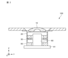
- FIG. 2 is a cross-sectional view showing an imaging device 100 including the vibrating device 1 of FIG.
- the vibrating device 1 can be used as an imaging device 100 by housing an imaging element 60 inside.
- the imaging device 100 includes the vibrating device 1 and the imaging device 60 .
- the imaging element 60 is connected to, for example, a substrate 61 or the like.
- the imaging element 60 can capture an image of an object to be imaged outside the vibration device 1 through the transparent body 10 of the vibration device 1 .
- the vibrating device 1 is fixed to the substrate 61 via the holding portion 50 .
- the translucent body 10 functions as a cover for protecting the imaging device accommodated in the vibrating device 1 from adhesion of foreign substances.
- Translucent body 10 may also function as an optically designed lens.
- the translucent body 10 has a translucency through which an energy ray or light having a wavelength detected by an imaging device is transmitted. In this embodiment, as shown in FIG. 1, the translucent body 10 is formed in a dome shape.
- the translucent body 10 for example, glass such as soda glass, borosilicate glass, aluminosilicate glass, or quartz glass, translucent plastic, translucent ceramics, synthetic resin, or the like can be used. .
- the strength of the translucent body 10 can be increased by forming the translucent body 10 from, for example, tempered glass whose strength is improved by chemical strengthening or the like.
- the vibrating body 20 receives the vibration of the piezoelectric element 30 and vibrates the translucent body 10 .
- the vibrating body 20 is a tubular member having one end 20a, the other end 20b, and a side wall 20c connecting the one end 20a and the other end 20b, as shown in FIG.
- One end of the vibrating body 20 is connected to the translucent body 10 .
- the translucent body 10 and the vibrating body 20 can be connected by, for example, an adhesive.
- one end 20a of the vibrating body 20 is formed with a recess 20d for disposing the translucent body 10 thereon.
- one end 20a of the vibrating body 20 may be formed flat, and the translucent body 10 may be fixed to the one end 20a with an adhesive or the like.
- the vibrating body 20 has a first protruding portion 24 protruding inward from one end 20a and a second protruding portion 25 protruding inward from the other end 20b. Since the vibrating body 20 has such a shape, a part of the extended portion 21 and the second protruding portion 25 becomes a node with a small amount of displacement of the vibrating body 20 due to vibration.
- the material of the vibrating body 20 for example, metal, ceramics, or the like can be used.
- metals that can be used include stainless steel, 42 alloy, 50 alloy, invar, super invar, kovar, aluminum, and duralumin.
- it may be made of ceramics such as alumina and zirconia.
- the vibrating body 20 may be made of a semiconductor such as Si. Also, the vibrating body 20 may be subjected to an insulating coating such as alumite treatment.
- the extending portion 21 extends outward from the side wall 20c of the vibrating body 20, as shown in FIG.
- the vibrating body 20 is formed so as to extend outward from one end 20a.
- the extending portion 21 is a portion that becomes a node where the amount of displacement due to vibration is 0 when the vibrating body 20 is vibrating. Since the extending portion 21 serves as a vibration node, the vibration of the vibrating body 20 can be efficiently transmitted to the transparent body 10 without escaping to the extending portion 21 . Moreover, even if foreign matter such as water droplets or mud adheres to the extending portion 21, the influence on the vibration performance of the vibrating body 20 can be reduced.
- the extending portion 21 is a flange formed on the side wall of the vibrating body 20 on the one end 20a side. Therefore, the extending portion 21 has a ring-like shape when viewed from the axial direction (Z direction) of the vibrating body 20 . Further, the extending portion 21 and the vibrating body 20 are integrally formed. The extending portion 21 is formed in a plate shape having a first surface 21a on the one end 20a side of the vibrating body 20 and a second surface 21b on the other end 20b side of the vibrating body 20 .
- the thickness t1 of the extended portion 21 is preferably 0.25 mm or more and 1 mm or less, for example. More preferably, the thickness t1 of the extended portion 21 is 0.5 mm. In this case, the displacement amount of the extending portion 21 can be reduced, and the vibration of the vibrating body 20 can be efficiently transmitted to the translucent body 10 .
- the width w1 of the extended portion 21 is preferably 4 mm or more and 6 mm or less, for example. More preferably, the width w1 of the extended portion 21 is 4.6 mm. In this case, the displacement amount of the extending portion 21 can be reduced, and the vibration of the vibrating body 20 can be efficiently transmitted to the translucent body 10 .
- the width w1 of the extending portion 21 indicates the length of the extending portion 21 protruding from the side wall 20c of the vibrating body 20. As shown in FIG.
- the extending portion 21 is provided in a direction orthogonal to the axial direction (Z direction) of the vibrating body 20 from one end 20a of the vibrating body. That is, the extending portion 121 is formed such that the one end 20a of the vibrating body 20 and the first surface 21a of the extending portion 21 are substantially at the same height in the axial direction of the vibrating body 20 .
- the extending portion 21 and the one end 20a of the vibrating body 20 are formed at substantially the same height, the amount of displacement due to vibration of the extending portion 21 can be reduced, and the vibration performance of the vibrating device 1 can be improved.
- the piezoelectric element 30 is arranged at the other end 20 b of the vibrating body 20 .
- the piezoelectric element 30 is formed in a ring shape when viewed from the axial direction (Z direction) of the vibrating body 20 .
- the piezoelectric element 30 can be fixed to the other end 20b of the vibrating body 20 with an adhesive, for example.
- the shape of the piezoelectric element 30 is not limited to a ring shape, and may be any shape that allows the vibrating body 20 to vibrate.
- the piezoelectric element 30 has a piezoelectric body and electrodes.
- materials that form the piezoelectric body include barium titanate (BaTiO 3 ), lead zirconate titanate (PZT: PbTiO 3 .PbZrO 3 ), lead titanate (PbTiO 3 ), and lead metaniobate (PbNb 2 O). 6 ), appropriate piezoelectric ceramics such as bismuth titanate ( Bi4Ti3O12 ) and (K, Na) NbO3 , or appropriate piezoelectric single crystals such as LiTaO3 and LiNbO3 can be used.
- the electrodes may be Ni electrodes, for example.
- the electrode may be an electrode made of a metal thin film such as Ag or Au, which is formed by a sputtering method.
- the electrodes can be formed by plating or vapor deposition in addition to the sputtering method.
- the piezoelectric element 30 is controlled by, for example, a control unit.
- the control unit has, for example, an excitation circuit for applying a drive signal to generate vibrations.
- the excitation circuit is connected to the piezoelectric element 30 via, for example, a power supply conductor.
- the piezoelectric element 30 vibrates the vibrating body 20 in the thickness direction (Z direction) of the vibrating device 1 based on the drive signal from the excitation circuit.
- the piezoelectric element 30 vibrates, the vibrating body 20 vibrates in the thickness direction (Z direction).
- the translucent body 10 is vibrated by vibrating the vibrating body 20 , and foreign matter such as water droplets adhering to the translucent body 10 is removed.
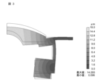
- FIG. 3 is a diagram showing a simulation result of the displacement amount distribution in the vibration device 1 of Embodiment 1.
- FIG. 3 For the simulation, Femtet manufactured by Murata Software Co., Ltd. was used to perform piezoelectric analysis (resonance analysis).
- the calculation conditions for the simulation of FIG. 3 are as follows.
- the material of the transparent body 10 corresponds to soda glass with a density of 2.48 g/cm 3 and a Young's modulus of 73 GPa.
- the diameter of the translucent body 10 is 14 mm.
- the material of the vibrating body 20 corresponds to SUS420J2 with a density of 7.75 g/cm 3 and a Young's modulus of 200 GPa.
- the piezoelectric element 30 has a density of 7.83 g/cm 3 , and a voltage of 60 Vp-p is applied to the upper and lower surfaces of the piezoelectric element 30 (the surface in contact with the vibrating body 20 and the surface on the opposite side).
- the piezoelectric element has an outer diameter of 16 mm, an inner diameter of 10 mm, and a thickness of 1 mm. In FIG. 12, the lighter the color, the greater the amount of displacement.
- the extension portion 21 has a displacement amount close to 0 and hardly vibrates. This indicates that the extension 21 is a vibration node.
- the amount of displacement is the largest near the center of the translucent body 10 . From this, it can be seen that the vibration of the vibrating body 20 is suppressed from escaping to the extending portion 21 and is transmitted to the translucent body 10 . Therefore, foreign matter such as water droplets or mud adhering to the translucent body 10 can be efficiently removed.
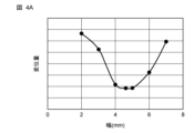
- FIG. 4A is a graph showing the width dependence of the amount of displacement of the extending portion 21.
- FIG. FIG. 4B is a graph showing thickness dependence of the amount of displacement of the extending portion 21 .
- FIG. 4A shows the dependence of the amount of displacement of the extending portion 21 on the width w1 (see FIG. 1) when the thickness t1 (see FIG. 1) of the extending portion 21 is fixed at 0.5 mm.
- FIG. 4B shows the dependence of the amount of displacement of the extending portion 21 on the thickness t1 when the width w1 of the extending portion 21 is fixed at 4.6 mm.
- the displacement amount in the graphs of FIGS. 4A and 4B was calculated as the maximum displacement amount of the extending portion 21 .
- the width w1 of the extending portion 21 is 4 mm or more and 6 mm or less, the amount of displacement of the extending portion 21 can be kept small. Therefore, the width w1 of the extending portion 21 is preferably 4 mm or more and 6 mm or less. Further, when the width w1 of the extended portion 21 was 4.6 mm, the amount of displacement of the extended portion 121 was the smallest. Therefore, more preferably, the width w1 of the extended portion 121 is 4.6 mm.
- the thickness t1 of the extended portion 21 is 0.25 mm or more and 1 mm or less, the amount of displacement of the extending portion 21 can be kept small. Therefore, the thickness t1 of the extended portion 21 is preferably 0.25 mm or more and 1 mm or less. Further, when the thickness t1 of the extended portion 21 was 0.5 mm, the amount of displacement of the extended portion 21 was the smallest. Therefore, more preferably, the thickness t1 of the extended portion 21 is 0.5 mm.
- the vibrating device 1 includes a translucent body 10, a vibrating body 20, an extending portion 21, and a piezoelectric element 30.
- the vibrating body 20 is a cylindrical member having one end 20a, the other end 20b, and a side wall 20c connecting the one end 20a and the other end 20b. to vibrate.
- the extending portion 21 extends outward from the side wall 20c of the vibrating body 20 .
- the piezoelectric element 30 is arranged at the other end 20 b of the vibrating body 20 .
- the extending portion 21 becomes a vibration node, the translucent body 10 can be vibrated efficiently. Further, even if a foreign substance such as a water droplet adheres to the extending portion 21, since the extending portion 21 is a vibration node, the influence on the vibration of the translucent body 10 can be reduced. Further, even if there are manufacturing variations, by forming the nodes in the extending portions 21, the vibration can be efficiently transmitted to the translucent body 10.
- the extending portion 21 extends outward from one end 20a of the vibrating body 20 . With such a configuration, it is possible to reduce the amount of displacement caused by the vibration of the extending portion 21 and improve the vibration performance of the vibrating device 1 .
- the extending portion 21 is ring-shaped has been described, but the shape of the extending portion 21 is not limited to this.
- the extending portion 21 may have any shape as long as it extends outward from the side wall 20c of the vibrating body 20 .
- the imaging device 100 includes a vibrating device 1 and an imaging element 60 arranged inside the vibrating device 1 .
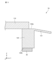
- FIG. 5 is a partial cross-sectional view showing a vibration device 1A according to Modification 1 of Embodiment 1.
- the extending portion 121 may be bent toward the other end 120b of the vibrating body 120.
- the vibrating body 120 may be formed in a cylindrical shape without the first protrusion and the second protrusion.
- the translucent body 110 may be formed in a plate shape. In this case, the same effects as in the first embodiment can be obtained with a simple configuration.
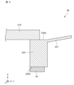
- FIG. 6 is a partial cross-sectional view showing a vibration device 1B according to Modification 2 of Embodiment 1.
- FIG. 6 the extending portion 221 may be bent toward the one end 220a of the vibrating body 220. As shown in FIG. In this case, the same effects as in the first embodiment can be obtained with a simple configuration.
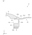
- FIG. 7 is a partial cross-sectional view showing a vibration device 1C according to Modification 3 of Embodiment 1.
- the extending portion 321 may be formed extending outward from the one end 320a side of the vibrating body 320 .
- the extending portion 321 extends outward from the side wall 320c on the one end 320a side of the vibrating body 320.
- the extending portion 321 is composed of a first portion 321c, a second portion 321d, and a third portion 321e.
- the first portion 321 c extends from the side wall 320 c of the vibrating body 320 in a direction orthogonal to the axial direction (Z direction) of the vibrating body 320 .
- the second portion 321d extends from the first portion 321c toward the one end 320a.
- the third portion 321e extends from the second portion 321d in a direction orthogonal to the axial direction (Z direction) of the vibrating body 320. As shown in FIG. Such a configuration facilitates the flow of water droplets or the like adhering to the extending portion 321 to the outside.
- the second portion 321d may extend from the first portion 321c toward the other end 320b.
- the vibrating body 320 has a first protruding portion 324 protruding inward from one end 320a and a second protruding portion 325 protruding inward from the other end 320b.
- the extended portion 321 and part of the second projecting portion 325 serve as vibration nodes. Therefore, a member such as a holding portion can be connected to the second projecting portion 325 without affecting the vibration of the translucent body 10 .
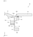
- FIG. 8 is a partial cross-sectional view showing the vibrating device 2 according to the second embodiment.
- the second embodiment differs from the first embodiment in that a weight 422 is arranged at the tip of the extending portion 421 .
- a weight 422 is arranged along the outer periphery of the second surface 421b of the extending portion 421.
- the weight 422 is formed in a ring shape along the outer periphery of the second surface 421b of the extending portion 421.
- the weight can be made of the same material as the extension 421, for example.
- the extending portion 421 and the weight 422 are integrally formed, but the extending portion 21 and the weight 422 may be formed of separate members. In that case, a weight 422 made of another member may be attached to the extension portion 421 .
- the weight 422 By arranging the weight 422 on the extending portion 421 , the amount of displacement of the extending portion 421 can be further reduced, and the vibration of the vibrating body 420 can be efficiently transmitted to the translucent body 10 .
- the amount of displacement of the extending portion 421 By arranging a weight 422 on the extending portion 421 formed in a plate shape to add weight, the amount of displacement of the extending portion 421 can be reduced. As a result, the vibration performance of the vibration device 2 can be improved.
- the vibrating device 2 has a configuration in which a weight 422 is arranged on an extending portion 421 extending from one end 420a of a vibrating body 420.
- FIG. 9A is a diagram showing a simulation result of displacement amount distribution in the vibration device 2 of FIG.
- Femtet manufactured by Murata Software Co., Ltd. was used to perform piezoelectric analysis (resonance analysis).
- the calculation conditions for the simulation of FIG. 9A are as follows.
- the material of the transparent body 10 corresponds to soda glass with a density of 2.48 g/cm 3 and a Young's modulus of 73 GPa.
- the diameter of the translucent body 10 is 14 mm.
- the material of the vibrating body 420 corresponds to SUS420J2 with a density of 7.75 g/cm 3 and a Young's modulus of 200 GPa.
- the piezoelectric element 30 has a density of 7.83 g/cm 3 , and a voltage of 60 Vp-p is applied to the upper and lower surfaces of the piezoelectric element 30 (the surface in contact with the vibrating body 420 and the surface on the opposite side).
- the piezoelectric element 30 has an outer diameter of 16 mm, an inner diameter of 10 mm, and a thickness of 1 mm. In FIG. 9A, the lighter the color, the greater the amount of displacement.
- the extending portion 421 and the weight 422 are vibration nodes. Further, by disposing the weight 422 on the extending portion 421, the amount of displacement of the extending portion 421 can be further reduced as compared with the case where the extending portion 421 has no weight.
- the weight 422 serves as a vibration node, so that the vibration of the vibrating body 420 can be transmitted to the translucent body 10 more efficiently.
- the weight 422 also serves as a vibration node, even if a foreign object adheres to the weight 422, the vibration performance of the vibrating device 2 can be maintained without affecting the vibration.
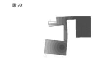
- FIG. 9B and 9C are diagrams showing resonance analysis results of the vibrating body 420 of the vibrating device 2.
- FIG. FIG. 9B shows the case when the phase is 0°
- FIG. 9C shows the case when the phase is 180°.
- the vibrating body 420 vibrates in a tuning fork resonance mode.
- two nodes are formed in the vibrating body 420 symmetrically about an intermediate position in1 (see FIG. 8) between the first projecting portion 424 and the second projecting portion 425 .
- One of the two nodes is the extension 421 and the weight 422 and the other node is part of the second protrusion 425 .
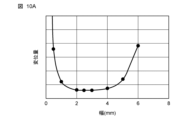
- FIG. 10A is a graph showing the width dependence of the displacement amount of the weight 422.
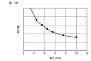
- FIG. 10B is a graph showing the thickness dependence of the amount of displacement of the weight 422 .
- FIG. 10A shows the dependence on the width w2 (see FIG. 8) of the weight 422 when the thickness t2 (see FIG. 8) of the weight 422 is fixed at 3.5 mm.
- FIG. 10B shows the dependence on the thickness t2 of the weight 422 when the width w2 of the weight 422 is fixed at 2.5 mm.
- the width w2 of the weight 422 is the length of the weight 422 in the outward direction from the side wall 420c of the vibrating body 420.
- the thickness t2 of the weight 422 is the length from the first surface 421a of the extending portion 421 to the lower end 422a (see FIG. 8) of the weight 422.
- FIG. 10A shows the width w2 (see FIG. 8) of the weight 422 when the thickness t2 (see
- the width w2 of the weight 422 is 1 mm or more and 5 mm or less, the amount of displacement of the weight 422 can be kept small. Therefore, the width w2 of the weight 422 is preferably 1 mm or more and 5 mm or less. Moreover, when the width w2 of the weight 422 was 2.5 mm, the amount of displacement of the weight 422 was the smallest. Therefore, more preferably, the width w2 of the weight 422 is 2.5 m.
- the thickness t2 of the weight 422 can be set to an arbitrary value depending on the trade-off between the size of the vibration device 2 and the vibration performance.
- a weight 422 is arranged on the second surface 421b of the extending portion 421 on the side of the other end 420b of the vibrating body 420.
- the weight 422 By arranging the weight 422 on the extending portion 421, it becomes easier to form a vibration node in the extending portion 421, so that the vibration of the vibrating body 420 can be transmitted to the translucent body 10 more efficiently.
- the weight 422 also serves as a vibration node, even if a foreign object adheres to the weight 422, the vibration performance of the vibrating device 2 can be maintained without affecting the vibration.
- the weight 422 is arranged on the second surface 421b of the extending portion 421 , but the present invention is not limited to this.
- the weight 422 may be arranged on either the first surface 421a on the one end 420a side of the vibrating body 520 or the second surface 421b on the other end 420b side.
- weight 422 is arranged on the extending portion 421
- the present invention is not limited to this.
- a plurality of weights may be arranged on either the first surface 421 a or the second surface 421 b of the extension portion 421 . In this case, each weight should be arranged at regular intervals.
- FIG. 11 is a partial cross-sectional view showing a vibration device 2A according to Modification 1 of Embodiment 2. As shown in FIG. As shown in FIG. 11 , the weight 522 may be arranged at a position other than the tip of the extension portion 521 . Even in such a configuration, the same effects as in the second embodiment can be obtained.
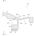
- FIG. 12 is a partial cross-sectional view showing a vibration device 2B according to Modification 2 of Embodiment 2.
- the extending portion 621 may have a first portion 621c, a second portion 621d, and a third portion 621e, and the weight 622 may be arranged on the third portion 621e.
- Such a configuration makes it easier for water droplets or the like adhering to the extending portion 621 to flow to the outside.
- FIG. 3 A vibrating device 3 according to a third embodiment of the present invention will be described. Note that in the third embodiment, differences from the second embodiment will be mainly described. In the third embodiment, the same reference numerals are assigned to the same or equivalent configurations as in the second embodiment. Moreover, in the third embodiment, the description overlapping with that in the second embodiment is omitted.
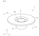
- FIG. 13 is a perspective view showing the vibrating device 3 according to the third embodiment.
- FIG. 14 is an exploded view of the vibration device 3 of FIG.
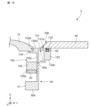
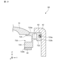
- FIG. 15 is a cross-sectional view of the vibrating device 3 of FIG. 13 taken along the line AA.
- FIG. 16 is an enlarged view of part of the vibration device 3 of FIG.
- a vibrating device 3 according to the third embodiment differs from the second embodiment in that it includes a cover 40 and a holding portion 50, as shown in FIGS. Further, the vibrating device 3 according to the third embodiment differs from the second embodiment in that a groove 723 is formed in the weight 722 and the seal member 62 is arranged in the groove 723 .
- a groove 723 is formed on the surface of the weight 722 (the first surface 721a of the extending portion 721).
- the groove 723 is formed in a ring shape along the outer circumference of the weight 722 when viewed from the axial direction (Z direction) of the vibrating body 720 .
- a seal member 62 is arranged in the groove 723 .
- the seal member 62 is an elastic member such as an O-ring.
- the cover 40 is a member that prevents foreign matter from entering the vibrating device 3 .
- the cover 40 is formed with a hole 40a through which the translucent body 10 is exposed.
- the cover 40 is arranged outside the translucent body 10 and attached to the extending portion 721 to contact the surface of the weight 722 .
- the cover 40 is formed in a plate shape having holes 40a.
- the vibrating device 3 can have a waterproof structure.
- the end 40b of the cover 40 on the side of the hole 40a is tapered so that the thickness decreases toward the translucent body 10. As shown in FIG.
- the vibrating device 3 can be covered without impairing the viewing angle of the imaging element, and both performance and reliability of the vibrating device 2 can be achieved. be able to.
- FIG. 17 is a diagram showing a simulation result of the displacement amount distribution in the vibration device 3 of Embodiment 3.
- FIG. 17 For the simulation, Femtet manufactured by Murata Software Co., Ltd. was used to perform piezoelectric analysis (resonance analysis).
- the calculation conditions for the simulation of FIG. 17 are as follows.
- the material of the transparent body 10 corresponds to soda glass with a density of 2.48 g/cm 3 and a Young's modulus of 73 GPa.
- the diameter of the translucent body 10 is 14 mm.
- the material of the vibrating body 20 corresponds to SUS420J2 with a density of 7.75 g/cm 3 and a Young's modulus of 200 GPa.
- the piezoelectric element 30 has a density of 7.83 g/cm 3 , and a voltage of 60 Vp-p is applied to the upper and lower surfaces of the piezoelectric element 30 (the surface in contact with the vibrating body 20 and the surface on the opposite side).
- the piezoelectric element has an outer diameter of 16 mm, an inner diameter of 10 mm, and a thickness of 1 mm. In FIG. 17, the lighter the color, the greater the amount of displacement.
- the extension part 721 and the weight 722 have a displacement amount close to 0 and hardly vibrate.
- the amount of displacement is the largest near the center of the translucent body 10 . From this, it can be seen that the vibration of the vibrating body 20 is suppressed from escaping to the extending portion 721 and is transmitted to the translucent body 10 . Therefore, foreign substances such as water droplets adhering to the transparent body 10 can be efficiently removed.
- the extending portion 721 is a vibration node.
- the cover 40 since the cover 40 is brought into contact with the vibration node, a waterproof structure can be realized while maintaining the vibration performance of the vibrating device 3 .
- a part of the second projecting portion 725 of the vibrating body 720 also serves as a vibration node. Therefore, by connecting the holding portion 50 to a part of the second protruding portion 725 , it is possible to obtain a structure that holds the vibration device 3 while suppressing the influence on the vibration performance of the vibration device 3 .
- the vibrating device 3 further includes a cover 40 having a hole 40 a for exposing the translucent body 10 , arranged outside the translucent body 10 and attached to the extending portion 721 to contact one weight 722 .
- One weight 722 is formed in an annular shape.
- a seal member 62 is arranged in a groove 723 provided on the surface of one weight 722 .
- the end 40b of the cover 40 on the side of the hole 40a may be tapered so that the thickness decreases toward the translucent body 10 .
- the end portion 40b of the cover 40 can be shaped appropriately according to the viewing angle of the imaging element arranged inside the vibration device 3.
- FIG. 18 is a partial cross-sectional view showing a vibration device 3A according to Modification 1 of Embodiment 3.
- the holding portion 52 may have a base portion 53 projecting outward from the other end 52b.
- the vibrating device 3 can be stably arranged on a substrate or the like, and the reliability of the vibrating device 3 can be improved.
- FIG. 19 is a partial cross-sectional view showing a vibration device 3B according to Modification 2 of Embodiment 3.
- FIG. 19 the hole-side end 41b of the cover 41 may not be tapered.
- the end portion 41b of the cover 41 can be formed in an appropriate shape according to the viewing angle of the imaging device arranged inside the vibration device 3B.
- FIG. 20 is a partial cross-sectional view showing a vibration device 3C according to Modification 3 of Embodiment 3.
- FIG. 9 the cover 42 may be bent. By forming the cover 42 to be bent, the waterproof performance of the vibrating device 3C can be improved, and the reliability can be enhanced.
- FIG. 21 is a partial cross-sectional view showing a vibration device 3D according to Modification 4 of Embodiment 3.
- FIG. 21 a groove 723a may be formed in the side surface 722b of the weight 722, and the seal member 62 may be arranged in the groove 723a.
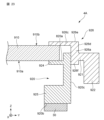
- FIG. 22 is a cross-sectional view showing a vibrating device 4 according to the fourth embodiment.
- the fourth embodiment differs from the first embodiment in that the vibrating device 4 includes a retainer 826 . Further, the fourth embodiment is different from the first embodiment in that the retainer 826 is provided with the extended portion 821 .
- the vibrating device 4 includes a retainer 826 arranged on the one end 820a side of the vibrating body 820 .
- the retainer 826 is a member for fixing the translucent body 810 to the vibrating body 820 .
- the transparent body 810 can be fixed by sandwiching the transparent body 810 between the retainer 826 and the vibrating body 820 .
- the retainer 826 has a first member 826a and a second member 826c.
- the first member 826 a is a tubular member attached to the side wall 820 c of the vibrating body 820 .
- the first member 826a extends inwardly from one end 826e of the retainer 826.
- the second member 826c extends inward from the inner surface 826b of the first member 826a and contacts the surface 810b opposite to the surface 810a of the translucent body 810 connected to the vibrating body.
- the extending portion 821 is provided at the other end 826f of the retainer 826 so as to extend outward from the outer surface 826d of the first member 826a.
- the other end 826f of the retainer 826 is located at substantially the same height as the one end 820a of the vibrating body 820 in the axial direction (Z direction) of the vibrating body 20. As shown in FIG. Therefore, in the axial direction (Z direction) of the vibrating body 820, the one end 820a of the vibrating body 820 and the extending portion 821 are arranged at substantially the same height.
- a weight 822 is provided at the tip of the extending portion 821 .
- the vibrating device 4 includes a retainer 826 arranged on the one end 820a side of the vibrating body 820 .
- the retainer 826 has a first member 826a and a second member 826c.
- the first member 826 a is a tubular member attached to the side wall 820 c of the vibrating body 820 .
- the second member 826c extends inward from the inner surface 826b of the first member 826a and contacts the surface 820b opposite to the surface 810a connected to the vibrating body 820 of the translucent body 810 .
- the extending portion 821 is provided extending outward from the outer surface 826d of the first member 826a of the retainer 826. As shown in FIG.
- the translucent body 810 can be firmly held, and the vibration of the vibrating body 820 can be efficiently transmitted to the translucent body 810 .
- FIG. 23 is a partial cross-sectional view showing a vibration device 4A according to Modification 1 of Embodiment 4.
- the extending portion 921 may be provided outward from an arbitrary position on the outer surface 926d of the first member 926a of the retainer 926.
- the extending portion 921 and the weight 922 serve as vibration nodes, and effects similar to those of the fourth embodiment can be obtained.
- the vibration device of the present invention can be applied to an on-vehicle camera used outdoors, a surveillance camera, or an optical sensor such as LiDAR.
Landscapes
- Engineering & Computer Science (AREA)
- Physics & Mathematics (AREA)
- Multimedia (AREA)
- Signal Processing (AREA)
- General Physics & Mathematics (AREA)
- Electromagnetism (AREA)
- Optics & Photonics (AREA)
- Mechanical Engineering (AREA)
- Camera Bodies And Camera Details Or Accessories (AREA)
Abstract
Un dispositif de vibration 1 de la présente invention comprend : un corps translucide 10 ; un corps de vibration 20 qui constitue un élément cylindrique comprenant une extrémité 20a, l'autre extrémité 20b, et une paroi latérale 20c reliant la première extrémité 20a et l'autre extrémité 20b, et est couplé au corps translucide 10 au niveau de la première extrémité 20a, et fait vibrer le corps translucide 10 ; une partie d'extension 21 qui s'étend vers l'extérieur à partir de la paroi latérale 20c du corps de vibration 20 ; et un élément piézoélectrique 30 qui est agencé au niveau de l'autre extrémité 20b du corps de vibration 20.
Priority Applications (2)
| Application Number | Priority Date | Filing Date | Title |
|---|---|---|---|
| JP2023563506A JP7779326B2 (ja) | 2021-11-26 | 2022-06-01 | 振動装置および撮像装置 |
| US18/652,016 US20240284059A1 (en) | 2021-11-26 | 2024-05-01 | Vibrating device and imaging device |
Applications Claiming Priority (2)
| Application Number | Priority Date | Filing Date | Title |
|---|---|---|---|
| JP2021-192472 | 2021-11-26 | ||
| JP2021192472 | 2021-11-26 |
Related Child Applications (1)
| Application Number | Title | Priority Date | Filing Date |
|---|---|---|---|
| US18/652,016 Continuation US20240284059A1 (en) | 2021-11-26 | 2024-05-01 | Vibrating device and imaging device |
Publications (1)
| Publication Number | Publication Date |
|---|---|
| WO2023095366A1 true WO2023095366A1 (fr) | 2023-06-01 |
Family
ID=86539065
Family Applications (1)
| Application Number | Title | Priority Date | Filing Date |
|---|---|---|---|
| PCT/JP2022/022360 Ceased WO2023095366A1 (fr) | 2021-11-26 | 2022-06-01 | Dispositif de vibration et dispositif d'imagerie |
Country Status (3)
| Country | Link |
|---|---|
| US (1) | US20240284059A1 (fr) |
| JP (1) | JP7779326B2 (fr) |
| WO (1) | WO2023095366A1 (fr) |
Citations (3)
| Publication number | Priority date | Publication date | Assignee | Title |
|---|---|---|---|---|
| WO2018198417A1 (fr) * | 2017-04-28 | 2018-11-01 | 株式会社村田製作所 | Dispositif de vibration |
| JP2020181079A (ja) * | 2019-04-25 | 2020-11-05 | 株式会社村田製作所 | 振動装置及び光学検出装置 |
| WO2021192387A1 (fr) * | 2020-03-27 | 2021-09-30 | 株式会社村田製作所 | Dispositif vibration et procédé de commande de vibration |
Family Cites Families (5)
| Publication number | Priority date | Publication date | Assignee | Title |
|---|---|---|---|---|
| US10401618B2 (en) * | 2015-03-11 | 2019-09-03 | Texas Instruments Incorporated | Ultrasonic lens cleaning system with current sensing |
| EP3623059B1 (fr) * | 2017-05-12 | 2024-02-28 | Murata Manufacturing Co., Ltd. | Dispositif de vibration |
| WO2019130623A1 (fr) * | 2017-12-27 | 2019-07-04 | 株式会社村田製作所 | Dispositif vibratoire et dispositif de détection optique |
| WO2020003572A1 (fr) * | 2018-06-28 | 2020-01-02 | 株式会社村田製作所 | Dispositif de vibration et dispositif de détection optique |
| JP6962470B2 (ja) * | 2018-06-28 | 2021-11-05 | 株式会社村田製作所 | 振動装置 |
-
2022
- 2022-06-01 WO PCT/JP2022/022360 patent/WO2023095366A1/fr not_active Ceased
- 2022-06-01 JP JP2023563506A patent/JP7779326B2/ja active Active
-
2024
- 2024-05-01 US US18/652,016 patent/US20240284059A1/en active Pending
Patent Citations (3)
| Publication number | Priority date | Publication date | Assignee | Title |
|---|---|---|---|---|
| WO2018198417A1 (fr) * | 2017-04-28 | 2018-11-01 | 株式会社村田製作所 | Dispositif de vibration |
| JP2020181079A (ja) * | 2019-04-25 | 2020-11-05 | 株式会社村田製作所 | 振動装置及び光学検出装置 |
| WO2021192387A1 (fr) * | 2020-03-27 | 2021-09-30 | 株式会社村田製作所 | Dispositif vibration et procédé de commande de vibration |
Also Published As
| Publication number | Publication date |
|---|---|
| JPWO2023095366A1 (fr) | 2023-06-01 |
| US20240284059A1 (en) | 2024-08-22 |
| JP7779326B2 (ja) | 2025-12-03 |
Similar Documents
| Publication | Publication Date | Title |
|---|---|---|
| CN111842345B (zh) | 振动装置以及光学检测装置 | |
| US12477199B2 (en) | Vibration device and imaging device | |
| CN109076152B (zh) | 振动装置以及摄像装置 | |
| JP7099633B2 (ja) | 振動装置 | |
| JP7111258B2 (ja) | 振動装置及び振動制御方法 | |
| JP6943341B2 (ja) | 振動装置及び光学検出装置 | |
| CN112004613B (zh) | 振动装置和光学检测装置 | |
| CN113179672B (zh) | 振动装置和具备振动装置的摄像单元 | |
| US12386173B2 (en) | Vibration device and imaging device | |
| US11980914B2 (en) | Vibrating device and optical detection apparatus | |
| WO2021038942A1 (fr) | Dispositif de vibration et dispositif de détection optique | |
| JP7666662B2 (ja) | 振動装置および撮像装置 | |
| JP7779326B2 (ja) | 振動装置および撮像装置 | |
| JP7708211B2 (ja) | 光学モジュールおよび光学装置 | |
| JP7663134B2 (ja) | 光学モジュールおよび光学装置 | |
| JP7663133B2 (ja) | 光学モジュールおよび光学装置 | |
| JP7776020B2 (ja) | 光学装置、および光学装置を備える撮像ユニット | |
| JPWO2023100396A5 (fr) | ||
| WO2022113701A1 (fr) | Dispositif de vibration | |
| WO2020137262A1 (fr) | Dispositif de vibration et dispositif de détection optique |
Legal Events
| Date | Code | Title | Description |
|---|---|---|---|
| 121 | Ep: the epo has been informed by wipo that ep was designated in this application |
Ref document number: 22898151 Country of ref document: EP Kind code of ref document: A1 |
|
| ENP | Entry into the national phase |
Ref document number: 2023563506 Country of ref document: JP Kind code of ref document: A |
|
| NENP | Non-entry into the national phase |
Ref country code: DE |
|
| 122 | Ep: pct application non-entry in european phase |
Ref document number: 22898151 Country of ref document: EP Kind code of ref document: A1 |