WO2023095367A1 - スロットライナおよび回転電機 - Google Patents
スロットライナおよび回転電機 Download PDFInfo
- Publication number
- WO2023095367A1 WO2023095367A1 PCT/JP2022/023640 JP2022023640W WO2023095367A1 WO 2023095367 A1 WO2023095367 A1 WO 2023095367A1 JP 2022023640 W JP2022023640 W JP 2022023640W WO 2023095367 A1 WO2023095367 A1 WO 2023095367A1
- Authority
- WO
- WIPO (PCT)
- Prior art keywords
- insulating sheet
- sheet
- slot
- sheets
- laminated
- Prior art date
- Legal status (The legal status is an assumption and is not a legal conclusion. Google has not performed a legal analysis and makes no representation as to the accuracy of the status listed.)
- Ceased
Links
Images



Classifications
-
- H—ELECTRICITY
- H02—GENERATION; CONVERSION OR DISTRIBUTION OF ELECTRIC POWER
- H02K—DYNAMO-ELECTRIC MACHINES
- H02K3/00—Details of windings
- H02K3/30—Windings characterised by the insulating material
-
- H—ELECTRICITY
- H02—GENERATION; CONVERSION OR DISTRIBUTION OF ELECTRIC POWER
- H02K—DYNAMO-ELECTRIC MACHINES
- H02K1/00—Details of the magnetic circuit
- H02K1/04—Details of the magnetic circuit characterised by the material used for insulating the magnetic circuit or parts thereof
-
- H—ELECTRICITY
- H02—GENERATION; CONVERSION OR DISTRIBUTION OF ELECTRIC POWER
- H02K—DYNAMO-ELECTRIC MACHINES
- H02K21/00—Synchronous motors having permanent magnets; Synchronous generators having permanent magnets
- H02K21/12—Synchronous motors having permanent magnets; Synchronous generators having permanent magnets with stationary armatures and rotating magnets
- H02K21/14—Synchronous motors having permanent magnets; Synchronous generators having permanent magnets with stationary armatures and rotating magnets with magnets rotating within the armatures
- H02K21/16—Synchronous motors having permanent magnets; Synchronous generators having permanent magnets with stationary armatures and rotating magnets with magnets rotating within the armatures having annular armature cores with salient poles
-
- H—ELECTRICITY
- H02—GENERATION; CONVERSION OR DISTRIBUTION OF ELECTRIC POWER
- H02K—DYNAMO-ELECTRIC MACHINES
- H02K3/00—Details of windings
- H02K3/32—Windings characterised by the shape, form or construction of the insulation
- H02K3/34—Windings characterised by the shape, form or construction of the insulation between conductors or between conductor and core, e.g. slot insulation
-
- H—ELECTRICITY
- H02—GENERATION; CONVERSION OR DISTRIBUTION OF ELECTRIC POWER
- H02K—DYNAMO-ELECTRIC MACHINES
- H02K3/00—Details of windings
- H02K3/32—Windings characterised by the shape, form or construction of the insulation
- H02K3/34—Windings characterised by the shape, form or construction of the insulation between conductors or between conductor and core, e.g. slot insulation
- H02K3/345—Windings characterised by the shape, form or construction of the insulation between conductors or between conductor and core, e.g. slot insulation between conductor and core, e.g. slot insulation
-
- H—ELECTRICITY
- H02—GENERATION; CONVERSION OR DISTRIBUTION OF ELECTRIC POWER
- H02K—DYNAMO-ELECTRIC MACHINES
- H02K3/00—Details of windings
- H02K3/46—Fastening of windings on the stator or rotor structure
- H02K3/48—Fastening of windings on the stator or rotor structure in slots
- H02K3/487—Slot-closing devices
-
- Y—GENERAL TAGGING OF NEW TECHNOLOGICAL DEVELOPMENTS; GENERAL TAGGING OF CROSS-SECTIONAL TECHNOLOGIES SPANNING OVER SEVERAL SECTIONS OF THE IPC; TECHNICAL SUBJECTS COVERED BY FORMER USPC CROSS-REFERENCE ART COLLECTIONS [XRACs] AND DIGESTS
- Y02—TECHNOLOGIES OR APPLICATIONS FOR MITIGATION OR ADAPTATION AGAINST CLIMATE CHANGE
- Y02T—CLIMATE CHANGE MITIGATION TECHNOLOGIES RELATED TO TRANSPORTATION
- Y02T10/00—Road transport of goods or passengers
- Y02T10/60—Other road transportation technologies with climate change mitigation effect
- Y02T10/64—Electric machine technologies in electromobility
Definitions
- the present invention relates to a slot liner and a rotating electric machine.
- a rotating electric machine such as an electric motor or a generator has a cylindrical stator core, conducting wires (coils), and slot liners.
- a plurality of spaces (hereinafter referred to as “slots”) through which the conductor wires pass are arranged at equal intervals on the inner peripheral surface of the stator core.
- a slot liner is disposed within the slot and provides insulation between the stator core and the conductors. Both ends of the slot liner protrude from the open ends of the slot to prevent contact between the conductors and the open ends of the slot.
- the portion of the conductor that protrudes from the open end is, for example, a ring-shaped bundle of conductors that is incorporated into the slot.
- a portion protruding from the end of the slot liner is formed together with a bundle of other conductor wires. Therefore, both ends of the slot liner may be damaged by being subjected to a load such as bending stress when the conductor is formed.
- both ends of the slot liner are reinforced by bonding reinforcing sheets made of polymer material such as epoxy or aramid to both ends of the slot liner.
- the insulation of the slot liner depends on the structure of the slot liner and may be insufficient. Therefore, there is room for improvement in the structure of the slot liner.
- An object of the present invention is to provide a reinforced slot liner and a rotating electric machine without deterioration of insulation.
- a slot liner is a slot liner that is arranged in a slot of a stator core provided in a rotating electric machine and insulates a conductor passing through the slot from the stator core, and comprises a plurality of insulating sheets. is laminated, and has a laminated insulating sheet having a length longer than the length of the stator core in the axial direction of the rotating shaft provided in the rotating electric machine, and a pair of reinforcing sheets for reinforcing the laminated insulating sheet.
- the laminated insulating sheet includes an outer insulating sheet in contact with the inner surface of the slot and an inner insulating sheet in contact with the conductor, and each of the pair of reinforcing sheets is arranged in the axial direction on the outer side. a folded portion that is folded so as to cover an end surface of an insulating sheet and covers the end surface of the outer insulating sheet; a first end portion disposed between the inner surface of the slot and the outer insulating sheet; and the outer insulating sheet. a second end positioned between the sheet and the inner insulating sheet.
- a rotating electric machine has a slot liner according to one embodiment of the present invention.
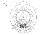
- FIG. 1 is a schematic diagram showing an embodiment of a rotary electric machine according to the present invention
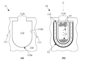
- FIG. FIG. 2 is a schematic cross-sectional view of the stator portion of the rotating electric machine of FIG. 1 taken along line AA
- (a) is a schematic enlarged cross-sectional view of a stator core provided in the rotating electrical machine of FIG. be.
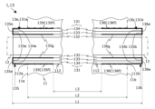
- BRIEF DESCRIPTION OF THE DRAWINGS It is a schematic perspective view which shows embodiment of the slot liner which concerns on this invention, (a) shows one end part side of a slot liner, (b) shows the other end part side of a slot liner.
- FIG. 5 is a schematic diagram of the slot liner of FIG. 4 as seen from arrow C in FIG.
- FIG. 3 (a) is a schematic enlarged cross-sectional view showing an example of an insulating sheet provided in the slot liner of FIG. 4, and (b) is a schematic enlarged cross-sectional view showing another example.
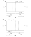
- 5A and 5B are schematic plan views of reinforcing sheets provided in the slot liner of FIG. 4;
- FIG. FIG. 5 is a schematic diagram showing a modification of the slot liner according to the present invention.
- a rotating electrical machine is, for example, a canned motor pump that conveys a high-temperature liquid (such as oil).
- a high-temperature liquid such as oil
- FIG. 1 is a schematic diagram showing an embodiment of a rotating electric machine according to the present invention. In the figure, for convenience of explanation, part of the internal structure of the rotating electric machine 1 is indicated by broken lines.
- the rotating electric machine 1 has a stator 10 , a rotor 20 and a rotating shaft 30 .
- FIG. 2 is a schematic cross-sectional view of the stator 10 portion taken along line AA in FIG.
- the rotor 20 and the rotating shaft 30 are indicated by a two-dot chain line.
- illustration of a part of the stator 10 is omitted.
- the stator 10 generates a rotating magnetic field that rotates the rotor 20 .
- the stator 10 comprises a stator core 11 , a plurality of conductors 12 , a plurality of slot liners 13 and a plurality of wedges 14 .
- the stator core 11 holds the conducting wire 12 .
- the shape of the stator core 11 is cylindrical.
- Stator core 11 has a plurality of teeth 111 and a plurality of slots 112 .
- circumferential direction means the circumferential direction of the stator core 11 (direction indicated by arrow CD in FIG. 2).
- Axial direction means a direction along the rotation axis of the rotor 20 (rotating shaft 30) (the direction indicated by arrow AD in FIG. 1).
- the tooth 111 defines a slot 112. In the circumferential direction, the teeth 111 are evenly spaced on the inner peripheral surface of the stator core 11 .
- FIG. 3A is a schematic enlarged cross-sectional view of the stator core 11 at the B1 portion of FIG. 2
- FIG. 3B is a schematic enlarged cross-sectional view of the stator 10 at the B2 portion of FIG.
- the size (thickness) of each member is intentionally emphasized rather than the actual size, in order to clarify the positional relationship of each member that constitutes the slot liner 13 .
- FIG. 2B the size (thickness) of each member is intentionally emphasized rather than the actual size, in order to clarify the positional relationship of each member that constitutes the slot liner 13 .
- the tip of the tooth 111 protrudes toward both sides in the circumferential direction. That is, the shape of the tooth 111 is substantially T-shaped when viewed in the axial direction.
- the slot 112 is a space formed between two teeth 111, 111 adjacent in the circumferential direction.
- the slots 112 are arranged on the inner peripheral surface of the stator core 11 at regular intervals.
- the slots 112 are formed over the entire length of the stator core 11 in the axial direction.
- open ends 112a having the same shape as the cross section of the slot 112 (cross section in the direction orthogonal to the axial direction) are formed on both end faces 11a and 11b (see FIGS. 1, 4 and 5; the same shall apply hereinafter) of the stator core 11.
- 112b see FIG. 4, hereinafter the same
- a slit-shaped opening 112c is formed between the tips of the two teeth 111, 111 forming the slot 112. As shown in FIG.
- the conductors 12 are passed through corresponding slots 112 to form coils that generate a rotating magnetic field in the stator 10 .
- the conducting wire 12 is composed of, for example, three-phase windings of U-phase, V-phase, and W-phase. Both ends (hereinafter referred to as “coil ends”), which are part of the conductor 12 , are arranged to protrude from open ends 112 a and 112 b of the slot 112 in the axial direction.
- another part of the conductor 12 (part other than the coil end) is arranged in the corresponding slot 112 by bundling the conductor 12 into a ring-shaped bundle.
- the coil end of the conducting wire 12 is, for example, bent in the circumferential direction and formed by being bundled with other conducting wires.
- the slot liner 13 is an insulating material that insulates between the stator core 11 and the conductor 12 . Slot liners 13 are positioned within corresponding slots 112 . A specific configuration of the slot liner 13 will be described later.
- the wedges 14 prevent the conductors 12 and slot liners 13 from falling out of the corresponding slots 112 .
- the wedges 14 are arranged in the corresponding slots 112 and close the openings 112c of the slots 112 from the inside.
- the rotor 20 rotates due to the rotating magnetic field generated in the stator 10 .
- the shape of the rotor 20 is cylindrical.
- Rotor 20 is housed in stator core 11 .
- the rotating shaft 30 is rotated by the rotation of the rotor 20 and transmits rotational power to the impeller (not shown) of the rotating electric machine 1 .
- the shape of the rotating shaft 30 is cylindrical.
- the rotating shaft 30 is inserted through the rotor 20 and fixed.
- FIG. 4 is a schematic perspective view showing an embodiment of a slot liner (slot liner 13) according to the present invention, where (a) shows one end 13a side of the slot liner 13, and (b) shows the slot liner. The other end 13b side of 13 is shown.
- FIG. 5 is a schematic diagram of the slot liner 13 as seen from arrow C in FIG. In FIGS. 4 and 5, the size (thickness) of each member is intentionally emphasized rather than the actual size in order to clarify the positional relationship of each member that constitutes the slot liner 13. As shown in FIG. 4 and 5, for convenience of explanation, the stator core 11 and a part of the conducting wire 12 are indicated by two-dot chain lines.
- the slot liner 13 includes a laminated insulating sheet 131 and a pair of reinforcing sheets 135,136.
- the laminated insulating sheet 131 includes a plurality of (three in the present embodiment) insulating sheets 132, 133, and 134.
- the insulating sheet 132 is an example of the inner insulating sheet in the present invention
- the insulating sheet 133 is an example of the intermediate insulating sheet in the present invention
- the insulating sheet 134 is an example of the outer insulating sheet in the present invention. That is, the laminated insulating sheet 131 includes an inner insulating sheet, an intermediate insulating sheet, and an outer insulating sheet according to the present invention.
- Each of the insulating sheets 132 to 134 has a rectangular sheet shape having short sides and long sides.
- the insulating sheets 132 to 134 are shown to have different shapes (sizes). The shape of each of 132-134 is the same.
- FIG. 6(a) is a schematic enlarged sectional view showing one example of the insulating sheets 132-134
- (b) is a schematic enlarged sectional view showing another example of the insulating sheets 132-134.
- Each of the insulating sheets 132 and 134 is a laminated mica insulating sheet composed of a laminated mica base sheet MS1 and a glass cloth sheet GS.
- the laminated mica base material sheet MS1 is a sheet in which flake-like mica is bonded together with a resin. That is, the laminated mica base sheet MS1 contains laminated mica.
- the glass cloth sheet GS is a sheet woven from glass fibers. As shown in FIG. 6(a), the insulating sheets 132 and 134 are constructed by bonding a glass cloth sheet GS to one surface of the laminated mica base sheet MS1.
- the insulating sheet 133 is a peelable mica insulating sheet composed of a peelable mica base sheet MS2 and a glass cloth sheet GS.
- the mica release base sheet MS2 is a sheet using mica release as a base material. That is, the mica release base sheet MS2 contains mica release. As shown in FIG. 6(a), the insulating sheet 133 is formed by bonding a glass cloth sheet GS to one surface of a peelable mica base sheet MS2.
- the laminated mica insulating sheet has higher flexibility than the peeled mica insulating sheet.
- the peeled mica insulating sheet has higher insulating properties than the laminated mica insulating sheet and is more expensive than the laminated mica insulating sheet.
- each insulating sheet in the present invention may be configured by laminating glass cloth sheets on both sides of a laminated mica base sheet or a peeled mica base sheet.
- the laminated insulating sheet 131 is configured by laminating three insulating sheets 132 to 134 . Specifically, when viewed in the axial direction, the insulating sheets 132 to 134 are arranged in the order of insulating sheet 132, insulating sheet 133, and insulating sheet 134 from the inner side (conductor 12 side) to the outer side (inner surface 112d side of slot 112). Laminated. That is, the insulating sheet 132 is overlaid on one side of the insulating sheet 133 , and the insulating sheet 134 is overlaid on the other side of the insulating sheet 133 .
- the peeled mica insulating sheet is sandwiched between two laminated mica insulating sheets.
- the insulating sheets 132 and 134 support the insulating sheet 133, thereby preventing concentration of stress and preventing the insulating sheet 133 (peeling mica) from folding.
- FIG. 7(a) is a schematic plan view of the reinforcing sheet 135, and (b) is a schematic plan view of the reinforcing sheet 136.
- FIG. 7 In the following description, for convenience of explanation, the horizontal direction of FIG. 7 (the direction indicated by arrow LD in FIG. 7) is defined as the "long side direction".
- the reinforcing sheets 135, 136 reinforce both ends 131a, 131b (see FIGS. 4 and 5) of the laminated insulating sheet 131.
- the reinforcing sheets 135 and 136 are, for example, insulating sheets made of polymeric material such as polyimide.
- the reinforcing sheets 135 and 136 are shaped like rectangular sheets.
- the reinforcing sheet 135 has four edges 135a, 135b, 135c, 135d, a folded portion 135e, a first half portion 135f, and a second half portion 135g.
- Edge sides 135a and 135b are sides orthogonal to the long side direction, and edge sides 135c and 135d are sides parallel to the long side direction.
- the folded portion 135e is a belt-like (or linear) portion located in the center of the reinforcing sheet 135 in the long-side direction.
- the first half portion 135f is a portion of the reinforcing sheet 135 closer to the end side 135a than the folded portion 135e.
- the second half portion 135g is a portion of the reinforcing sheet 135 closer to the end side 135b than the folded portion 135e.
- the reinforcing sheet 136 has four edges 136a, 136b, 136c, 136d, a folded portion 136e, a first half portion 136f, and a second half portion 136g.
- Edge sides 136a and 136b are sides perpendicular to the long side direction, and edge sides 136c and 136d are sides parallel to the long side direction.
- the folded portion 136e is a belt-like (or linear) portion located in the center of the reinforcing sheet 136 in the long-side direction.
- the first half portion 136f is a portion of the reinforcing sheet 136 closer to the end side 136a than the folded portion 136e.
- the second half portion 136g is a portion of the reinforcing sheet 136 closer to the end side 136b than the folded portion 136e.
- the reinforcing sheet 135 is attached to the end portion 131a of the laminated insulating sheet 131 with one end portions of the insulating sheets 133 and 134 sandwiched therebetween. Specifically, the reinforcing sheet 135 is folded back into a valley fold (or a mountain fold) starting from the folded portion 135e such that the first half portion 135f overlaps the second half portion 135g. At this time, the folded portion 135e covers the end surfaces 133a and 134a of the insulating sheets 133 and 134 on the one end side in the axial direction.
- the first half portion 135f is arranged outside the insulating sheet 134 (on the inner surface 112d side of the slot 112).
- the second half 135g is arranged between the insulating sheet 132 and the insulating sheet 133. As shown in FIG.
- the second half 135g is an example of a second end in the present invention.
- the reinforcing sheet 136 is attached to the end 131b of the laminated insulating sheet 131 with the other ends of the insulating sheets 133 and 134 sandwiched therebetween. Specifically, the reinforcing sheet 136 is folded back into a valley fold (or a mountain fold) starting from the folded portion 136e so that the first half portion 136f overlaps the second half portion 136g. At this time, the folded portion 136e covers the end surfaces 133b, 134b of the insulating sheets 133, 134 on the other end side in the axial direction. The first half portion 136f is arranged outside the insulating sheet 134 (on the inner surface 112d side of the slot 112). The second half 136 g is arranged between the insulating sheet 132 and the insulating sheet 133 . The second half 136g is an example of a second end in the present invention.
- the slot liner 13 is arranged in the corresponding slot 112 between the conductor 12 and the stator core 11 (the inner surface 112d of the slot 112). When viewed in the axial direction, the slot liner 13 is bent in a U shape along the inner surface 112d of the slot 112 so that the insulating sheet 132 faces inside. Insulating sheet 132 contacts wire 12 and insulating sheet 134 contacts inner surface 112 d of slot 112 .
- the length L1 of the laminated insulating sheet 131 (that is, the length of the slot liner 13) is longer than the length L2 of the stator core 11. Therefore, both ends 131a and 131b of the laminated insulating sheet 131 protrude from the open ends 112a and 112b of the slot 112 in the axial direction.
- the open end 112a of the slot 112 is positioned closer to the folded portion 135e than the center of the first half portion 135f of the reinforcing sheet 135 in the axial direction.
- the open end 112b of the slot 112 is located closer to the folded portion 136e than the center of the first half portion 136f of the reinforcing sheet 136.
- length L3 between reinforcing sheets 135 and 136 is shorter than length L2 of stator core 11 in the axial direction.
- first 135 f 1 is located between the inner surface 112 d of the slot 112 and the insulating sheet 134 .
- first 135 f 1 is located between the inner surface 112 d of the slot 112 and the insulating sheet 134 .
- first 135 f 1 is located between the inner surface 112 d of the slot 112 and the insulating sheet 134 .
- first half portion 136f of the reinforcing sheet 136 the portion closer to the edge side 136a than the open end 112b (in the present embodiment, approximately half of the first half portion 136f: 1 end”) 136f1 is disposed between the inner surface 112d of the slot 112 and the insulating sheet .
- the coil ends are bent in the circumferential direction during molding. Therefore, when the coil ends are formed, the ends 13 a and 13 b of the slot liner 13 receive a load (bending stress) directed in the circumferential direction from the conductor wire 12 . This load is particularly large at the open ends 112a and 112b of the slot 112. FIG. The reinforcing sheets 135, 136 distribute this stress. As a result, damage to the laminated insulating sheet 131, which is a mechanically fragile mica insulating sheet, is prevented.
- the second halves 135g and 136g of the reinforcing sheets 135 and 136 are arranged between the insulating sheets 132 and 133. That is, the reinforcing sheets 135 and 136 are not arranged inside the insulating sheet 132 (on the conductor 12 side). Therefore, in the slot liner 13 , the conductor 12 is not in contact with the reinforcing sheets 135 and 136 .
- the conducting wire 12 interferes with the reinforcing sheets 135 and 136 when the conducting wire 12 is passed through the slot liner 13.
- the reinforcing sheets 135 and 136 become obstacles, which may cause technical problems such as breakage of the reinforcing sheets 135 and 136 and a decrease in work efficiency of inserting the conductor 12 .
- reinforcing sheets 135 and 136 are not arranged inside insulating sheet 132 . Therefore, the above technical problem does not arise when the conductor 12 is inserted.
- the portions of the insulating sheets 133 and 134 having the length L3 and the insulating sheet 132 are not covered with the reinforcing sheets 135 and 136. Therefore, the heat generated by the current flowing through the conducting wire 12 is transmitted to the stator core 11 without passing through the reinforcing sheets 135 and 136 . That is, in the axial direction, high heat dissipation is obtained in the central portion of the stator core 11 . Further, even if reinforcing sheets 135 and 136 deteriorate in a high-temperature environment, the contact area between laminated insulating sheet 131 and stator core 11 does not change, and high heat dissipation is maintained.
- the slot liner 13 includes the laminated insulating sheet 131 formed by laminating a plurality of insulating sheets 132 to 134, and the pair of reinforcing sheets 135 for reinforcing the laminated insulating sheet 131. 136.
- Laminated insulating sheet 131 includes insulating sheet 134 contacting inner surface 112 d of slot 112 and insulating sheet 132 contacting conductor 12 .
- the length L1 of the laminated insulating sheets 131 is longer than the length L2 of the stator core 11 in the axial direction.
- the reinforcing sheets 135 and 136 are folded back so as to cover the end faces 133a, 133b, 134a and 134b of the insulating sheets 133 and 134, respectively.
- the reinforcing sheets 135, 136 have first ends 135f1, 136f1 and second halves 135g, 136g.
- First ends 135 f 1 and 136 f 1 are positioned between inner surface 112 d of slot 112 and insulating sheet 134 .
- the second halves 135g, 136g are arranged between the insulating sheet 132 and the insulating sheet 133. As shown in FIG. In other words, even if the laminated insulating sheet 131 includes the insulating sheet 133 as in this embodiment, the second halves 135g and 136g are arranged between the insulating sheets 132 and 134. become.
- the conductor 12 is not in contact with the reinforcing sheets 135,136.
- the insulation between stator core 11 and conducting wire 12 through deteriorated reinforcing sheets 135 and 136 does not deteriorate. That is, a reinforced slot liner 13 can be obtained without deterioration of insulation.
- technical problems such as breakage of the reinforcing sheets 135 and 136 and reduction in the efficiency of the conductor 12 insertion work do not occur.
- the laminated insulating sheet 131 includes the insulating sheet 133 arranged between the insulating sheets 132 and 134 .
- the second halves 135g, 136g are arranged between the insulating sheet 132 and the insulating sheet 133.
- the folded portion 135e covers the end surfaces 133a, 134a of the insulating sheets 133, 134, and the folded portion 136e covers the end surfaces 133b, 134b of the insulating sheets 133,134.
- the insulating sheets 132, 134 are configured by laminating the laminated mica base material sheet MS1 and the glass cloth sheet GS.
- the insulating sheet 133 is configured by laminating a peelable mica base sheet MS2 and a glass cloth sheet GS.
- the insulating sheets 132 and 134 support the insulating sheet 133, thereby preventing concentration of stress and preventing the insulating sheet 133 from folding.
- workability is improved when the slot liner 13 is arranged in the slot 112 . That is, a reinforced slot liner 13 can be obtained without deterioration of insulation.
- the reinforcing sheets 135 and 136 are sheets made of polymeric material such as polyimide. According to this configuration, the reinforcing sheets 135 and 136 have high heat resistance. Therefore, the reinforcing sheets 135 and 136 are less likely to deteriorate in a high-temperature environment. That is, a reinforced slot liner 13 can be obtained without deterioration of insulation.
- the rotating electrical machine 1 includes the slot liner 13 . According to this configuration, in the rotary electric machine 1 , the insulation deterioration and the technical problems described above do not occur. That is, a reinforced rotating electric machine 1 can be obtained without deterioration of insulation.
- the rotary electric machine according to the present invention is not limited to a canned motor pump that conveys high-temperature liquid. That is, for example, the rotating electric machine according to the present invention may be a motor pump for conveying liquid, a driving motor for an electric vehicle or the like, or a generator.
- the configuration of the laminated insulating sheet in the present invention is not limited to the present embodiment. That is, for example, the laminated insulating sheet in the present invention does not have to include any of the inner insulating sheet, the intermediate insulating sheet, or the outer insulating sheet. That is, for example, the laminated insulating sheet in the present invention may be composed of two layers of insulating sheets, an intermediate insulating sheet and an outer insulating sheet. Further, for example, the laminated insulating sheet in the present invention may be composed of four or more layers of insulating sheets including a plurality of intermediate insulating sheets.
- the intermediate insulating sheet in the present invention may be configured by laminating a plurality of insulating sheets (for example, peeled mica insulating sheets).
- the sizes (shapes) of the insulating sheets in the present invention do not have to be the same. That is, for example, when viewed in the axial direction, the size of each insulating sheet in the present invention may be adjusted so that the ends of each insulating sheet on the wedge side are aligned. According to this configuration, the wedge-side end portion of the inner insulating sheet does not protrude toward the wedge, and a space in which the wedge is arranged is secured.
- the material constituting the insulating sheet in the present invention is not limited to a peeled mica insulating sheet, a laminated mica insulating sheet, and a glass cloth sheet.
- the slot liner according to the present invention may comprise a second reinforcing sheet that assists the first half.
- the second reinforcing sheet may be formed to have substantially the same size as the first half and be arranged between the first half and the outer insulating sheet.
- the second reinforcing sheet may be configured by folding back the first half which is designed to be longer in the long side direction than the second half. According to this configuration, the effect of dispersing stress during coil end forming is improved.
- the size of the first end of the reinforcing sheet in the present invention is not limited to this embodiment as long as the first end is arranged between the inner surface of the slot and the outer insulating sheet.
- the material of the reinforcing sheet in the present invention is not limited to polyimide as long as it has heat resistance and insulating properties. That is, for example, the material of the reinforcing sheet in the present invention may be an insulating material that does not contain asbestos.
- the second half of the reinforcing sheet in the present invention may be arranged between the outer insulating sheet and the intermediate insulating sheet.
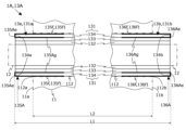
- FIG. 8 is a schematic diagram showing a modification of the slot liner according to the present invention. This figure shows a portion of a rotating electric machine 1A including a slot liner 13A in the modification from the same viewpoint as in FIG. In FIG. 8, the thickness of each member is intentionally emphasized rather than the actual size in order to clarify the positional relationship of each member constituting the slot liner 13A.
- the slot liner 13A includes a laminated insulating sheet 131 (132-134) and a pair of reinforcing sheets 135A, 136A.
- the folded portions 135Ae, 136Ae of the reinforcing sheets 135A, 136A cover the end surfaces 134a, 134b of the insulating sheet 134.
- the second halves 135Ag, 136Ag of the reinforcing sheets 135A, 136A are arranged between the insulating sheet 133 (middle insulating sheet) and the insulating sheet 134 (outer insulating sheet).
- the present modification differs from the above-described embodiment in that only both ends of the insulating sheet 134 of the laminated insulating sheet 131 are sandwiched between reinforcing sheets 135A and 136A.
- the stator core 11 and the conducting wire 12 are connected via the deteriorated reinforcing sheets 135A and 136A. No insulation degradation during In addition, when the conductor 12 is inserted, technical problems such as breakage of the reinforcing sheets 135A and 136A and reduction in efficiency of the conductor 12 insertion work do not occur.
- a first embodiment of the present invention is arranged in a slot (for example, slot 112) of a stator core (for example, stator core 11) provided in a rotating electric machine (for example, rotating electric machine 1, 1A) and passed through the slot.
- a slot liner eg, slot liner 13 that insulates a conductor (eg, conductor 12) from the stator core, and is configured by laminating a plurality of insulation sheets (eg, insulation sheets 132 to 134).
- Laminated insulating sheets e.g., length L1 having a length (e.g., length L1) longer than the length (e.g., length L2) of the stator core in the axial direction of the rotating shaft (e.g., rotating shaft 30) of the rotating electrical machine (e.g., A laminated insulating sheet 131) and a pair of reinforcing sheets (for example, reinforcing sheets 135 and 136) for reinforcing the laminated insulating sheet.
- a laminated insulating sheet 131 having a length (e.g., length L1) longer than the length (e.g., length L2) of the stator core in the axial direction of the rotating shaft (e.g., rotating shaft 30) of the rotating electrical machine (e.g., A laminated insulating sheet 131) and a pair of reinforcing sheets (for example, reinforcing sheets 135 and 136) for reinforcing the laminated insulating sheet.
- each of the pair of reinforcing sheets is aligned in the axial direction with the Folded portions (eg, folded portions 135e, 136e, 135Ae, 136Ae) that are folded so as to cover the end faces (eg, end faces 134a, 134b) of the outer insulating sheet and cover the end faces of the outer insulating sheet;
- a first end e.g., first ends 135f1, 136f1 positioned between an inner surface and the outer insulating sheet, and a second end positioned between the outer insulating sheet and the inner insulating sheet.
- a second embodiment of the present invention is based on the first embodiment, wherein the laminated insulating sheet comprises an intermediate insulating sheet (e.g., insulating sheet 133) disposed between the outer insulating sheet and the inner insulating sheet; in the axial direction, the folded portions (e.g., folded portions 135e, 136e) cover the end surfaces (e.g., end surfaces 133a, 133b) of the intermediate insulating sheet, and the second end covers the inner insulating sheet and the intermediate insulating sheet.
- the laminated insulating sheet comprises an intermediate insulating sheet (e.g., insulating sheet 133) disposed between the outer insulating sheet and the inner insulating sheet; in the axial direction, the folded portions (e.g., folded portions 135e, 136e) cover the end surfaces (e.g., end surfaces 133a, 133b) of the intermediate insulating sheet, and the second end covers the inner insulating sheet and the intermediate insulating sheet.
- the folded portions
- a third aspect of the present invention is based on the first aspect, wherein the laminated insulating sheet comprises an intermediate insulating sheet (e.g., insulating sheet 133) disposed between the outer insulating sheet and the inner insulating sheet; and the second end (eg, second halves 135Ag, 136Ag) is a slot liner (eg, slot liner 13A) disposed between the outer insulating sheet and the intermediate insulating sheet.
- the laminated insulating sheet comprises an intermediate insulating sheet (e.g., insulating sheet 133) disposed between the outer insulating sheet and the inner insulating sheet; and the second end (eg, second halves 135Ag, 136Ag) is a slot liner (eg, slot liner 13A) disposed between the outer insulating sheet and the intermediate insulating sheet.
- each of the outer insulating sheet and the inner insulating sheet is a base sheet containing laminated mica (for example, laminated mica base sheet MS1). , a glass cloth sheet woven with glass fibers (for example, glass cloth sheet GS), and the intermediate insulating sheet is a base sheet containing mica release (for example, mica release base sheet MS2). and a glass cloth sheet woven with glass fiber are laminated.
- laminated mica for example, laminated mica base sheet MS1
- a glass cloth sheet woven with glass fibers for example, glass cloth sheet GS
- the intermediate insulating sheet is a base sheet containing mica release (for example, mica release base sheet MS2).
- a glass cloth sheet woven with glass fiber are laminated.
- a fifth aspect of the present invention is the slot liner according to any one of the first to fourth aspects, wherein the reinforcing sheet is a polyimide sheet. According to this configuration, the reinforcing sheets 135 and 136 are less likely to deteriorate in a high-temperature environment.
- a sixth embodiment of the present invention is a rotating electric machine (for example, rotating electric machine 1, 1A) having the slot liner of any one of the first to fifth embodiments. According to this configuration, it is possible to obtain a rotating electric machine that does not cause the insulation deterioration and the technical problems described above.
Landscapes
- Engineering & Computer Science (AREA)
- Power Engineering (AREA)
- Insulation, Fastening Of Motor, Generator Windings (AREA)
- Iron Core Of Rotating Electric Machines (AREA)
Priority Applications (4)
| Application Number | Priority Date | Filing Date | Title |
|---|---|---|---|
| US18/693,696 US12095327B2 (en) | 2021-11-25 | 2022-06-13 | Slot liner and rotating electric machine |
| EP22898152.8A EP4391320A4 (de) | 2021-11-25 | 2022-06-13 | Nutauskleidung und elektrische drehmaschine |
| CN202280058968.2A CN117897887B (zh) | 2021-11-25 | 2022-06-13 | 槽衬及旋转电机 |
| KR1020247006916A KR102678250B1 (ko) | 2021-11-25 | 2022-06-13 | 슬롯 라이너 및 회전 전기 기기 |
Applications Claiming Priority (2)
| Application Number | Priority Date | Filing Date | Title |
|---|---|---|---|
| JP2021-191271 | 2021-11-25 | ||
| JP2021191271A JP7022254B1 (ja) | 2021-11-25 | 2021-11-25 | スロットライナおよび回転電機 |
Publications (1)
| Publication Number | Publication Date |
|---|---|
| WO2023095367A1 true WO2023095367A1 (ja) | 2023-06-01 |
Family
ID=80997548
Family Applications (1)
| Application Number | Title | Priority Date | Filing Date |
|---|---|---|---|
| PCT/JP2022/023640 Ceased WO2023095367A1 (ja) | 2021-11-25 | 2022-06-13 | スロットライナおよび回転電機 |
Country Status (7)
| Country | Link |
|---|---|
| US (1) | US12095327B2 (de) |
| EP (1) | EP4391320A4 (de) |
| JP (1) | JP7022254B1 (de) |
| KR (1) | KR102678250B1 (de) |
| CN (1) | CN117897887B (de) |
| TW (1) | TWI790182B (de) |
| WO (1) | WO2023095367A1 (de) |
Families Citing this family (1)
| Publication number | Priority date | Publication date | Assignee | Title |
|---|---|---|---|---|
| US12463446B2 (en) | 2023-05-22 | 2025-11-04 | Lg Energy Solution, Ltd. | Charging control apparatus and charging control method |
Citations (3)
| Publication number | Priority date | Publication date | Assignee | Title |
|---|---|---|---|---|
| JP2003109815A (ja) * | 2001-09-28 | 2003-04-11 | Nikkiso Co Ltd | 電気機器コイルの絶縁材 |
| JP2003111328A (ja) * | 2001-09-28 | 2003-04-11 | Nikkiso Co Ltd | 回転電機のスロットライナ |
| JP2015033323A (ja) * | 2013-08-02 | 2015-02-16 | ジーイー・アビエイション・システムズ・エルエルシー | スロットライナを有する電気機械 |
Family Cites Families (11)
| Publication number | Priority date | Publication date | Assignee | Title |
|---|---|---|---|---|
| JPS55141947A (en) * | 1979-04-24 | 1980-11-06 | Toshiba Corp | Insulation of channel of rotary electric machine |
| US5721397A (en) * | 1995-06-07 | 1998-02-24 | Weinberg; Martin J. | Electrical insulation and products protected thereby |
| JP3201262B2 (ja) * | 1996-05-30 | 2001-08-20 | 株式会社日立製作所 | 熱硬化性樹脂組成物,電機絶縁線輪,回転電機及びその製造方法 |
| WO2003030334A1 (en) * | 2001-09-28 | 2003-04-10 | Nikkiso Co., Ltd. | Insulating material for electric device coil and slot liner of rotating electric machine |
| JP5839851B2 (ja) * | 2011-06-23 | 2016-01-06 | 日立オートモティブシステムズ株式会社 | 回転電機 |
| JP5860782B2 (ja) * | 2012-08-31 | 2016-02-16 | 日立オートモティブシステムズ株式会社 | 回転電機及びその製造方法 |
| KR102166714B1 (ko) | 2013-09-24 | 2020-10-16 | 에스케이텔레콤 주식회사 | 회귀경로 제공 방법, 및 이를 위한 장치 |
| CN107925289B (zh) * | 2015-09-02 | 2020-07-21 | 日立汽车系统株式会社 | 定子线圈、配备定子线圈的定子、以及配备定子的旋转电机 |
| US10063117B2 (en) * | 2016-03-08 | 2018-08-28 | Hitachi Automotive Systems, Ltd. | Dynamo-electric machine with stator having trapezoid shape segmented coil |
| JP6944332B2 (ja) * | 2017-10-13 | 2021-10-06 | 株式会社日立インダストリアルプロダクツ | 回転電機 |
| WO2019123977A1 (ja) * | 2017-12-21 | 2019-06-27 | 日立オートモティブシステムズ株式会社 | 固定子の製造方法 |
-
2021
- 2021-11-25 JP JP2021191271A patent/JP7022254B1/ja active Active
-
2022
- 2022-06-13 CN CN202280058968.2A patent/CN117897887B/zh active Active
- 2022-06-13 KR KR1020247006916A patent/KR102678250B1/ko active Active
- 2022-06-13 WO PCT/JP2022/023640 patent/WO2023095367A1/ja not_active Ceased
- 2022-06-13 US US18/693,696 patent/US12095327B2/en active Active
- 2022-06-13 EP EP22898152.8A patent/EP4391320A4/de active Pending
- 2022-08-05 TW TW111129579A patent/TWI790182B/zh active
Patent Citations (3)
| Publication number | Priority date | Publication date | Assignee | Title |
|---|---|---|---|---|
| JP2003109815A (ja) * | 2001-09-28 | 2003-04-11 | Nikkiso Co Ltd | 電気機器コイルの絶縁材 |
| JP2003111328A (ja) * | 2001-09-28 | 2003-04-11 | Nikkiso Co Ltd | 回転電機のスロットライナ |
| JP2015033323A (ja) * | 2013-08-02 | 2015-02-16 | ジーイー・アビエイション・システムズ・エルエルシー | スロットライナを有する電気機械 |
Also Published As
| Publication number | Publication date |
|---|---|
| US20240266898A1 (en) | 2024-08-08 |
| JP2023077809A (ja) | 2023-06-06 |
| TW202322521A (zh) | 2023-06-01 |
| EP4391320A1 (de) | 2024-06-26 |
| JP7022254B1 (ja) | 2022-02-17 |
| US12095327B2 (en) | 2024-09-17 |
| CN117897887B (zh) | 2024-07-05 |
| EP4391320A4 (de) | 2024-12-11 |
| KR20240032180A (ko) | 2024-03-08 |
| TWI790182B (zh) | 2023-01-11 |
| CN117897887A (zh) | 2024-04-16 |
| KR102678250B1 (ko) | 2024-06-26 |
Similar Documents
| Publication | Publication Date | Title |
|---|---|---|
| CN109075647B (zh) | 旋转电机 | |
| US12294262B2 (en) | Rotating electric machine | |
| CN101785167B (zh) | 定子和采用该定子的旋转电机 | |
| US8587176B2 (en) | Salient pole concentrated winding stator for electric motor | |
| US20100244617A1 (en) | Stator having improved structure for restricting relative displacement between stator core and stator coil | |
| US11075559B2 (en) | Stator of rotating electric machine | |
| CN115149672B (zh) | 马达 | |
| US11496009B2 (en) | Stator, electric rotating machine, and electric-powered vehicle | |
| JP2010239740A (ja) | 回転電機用電機子 | |
| JP2010239739A (ja) | 相間絶縁シート | |
| CN110277856A (zh) | 旋转电机的定子 | |
| JP5392546B2 (ja) | 相間絶縁シート | |
| JP7453357B2 (ja) | 絶縁紙を備えた固定子、固定子を有する電動機、及び電動機の製造方法 | |
| JP7022254B1 (ja) | スロットライナおよび回転電機 | |
| CN115411862B (zh) | 定子 | |
| US8659204B2 (en) | Stator with interphase insulation sheet | |
| JP2007336725A (ja) | 回転電機の固定子 | |
| CN110637405B (zh) | 旋转电机的定子 | |
| JP2007312564A (ja) | 回転電機の固定子 | |
| JP4688729B2 (ja) | 回転電機の固定子 | |
| JP2010183839A (ja) | 回転電機の固定子 | |
| JP2019118250A (ja) | 固定子および電動機 | |
| JP2010239738A (ja) | 相間絶縁シート | |
| JP2023165352A (ja) | ステータ | |
| CN112953042A (zh) | 旋转电机的定子 |
Legal Events
| Date | Code | Title | Description |
|---|---|---|---|
| 121 | Ep: the epo has been informed by wipo that ep was designated in this application |
Ref document number: 22898152 Country of ref document: EP Kind code of ref document: A1 |
|
| ENP | Entry into the national phase |
Ref document number: 20247006916 Country of ref document: KR Kind code of ref document: A |
|
| WWE | Wipo information: entry into national phase |
Ref document number: 202280058968.2 Country of ref document: CN |
|
| WWE | Wipo information: entry into national phase |
Ref document number: 2022898152 Country of ref document: EP |
|
| ENP | Entry into the national phase |
Ref document number: 2022898152 Country of ref document: EP Effective date: 20240319 |
|
| NENP | Non-entry into the national phase |
Ref country code: DE |