WO2023095370A1 - 空気入りタイヤ - Google Patents
空気入りタイヤ Download PDFInfo
- Publication number
- WO2023095370A1 WO2023095370A1 PCT/JP2022/025154 JP2022025154W WO2023095370A1 WO 2023095370 A1 WO2023095370 A1 WO 2023095370A1 JP 2022025154 W JP2022025154 W JP 2022025154W WO 2023095370 A1 WO2023095370 A1 WO 2023095370A1
- Authority
- WO
- WIPO (PCT)
- Prior art keywords
- tire
- radial direction
- mass
- pneumatic tire
- tire radial
- Prior art date
- Legal status (The legal status is an assumption and is not a legal conclusion. Google has not performed a legal analysis and makes no representation as to the accuracy of the status listed.)
- Ceased
Links
Images



Classifications
-
- B—PERFORMING OPERATIONS; TRANSPORTING
- B60—VEHICLES IN GENERAL
- B60C—VEHICLE TYRES; TYRE INFLATION; TYRE CHANGING; CONNECTING VALVES TO INFLATABLE ELASTIC BODIES IN GENERAL; DEVICES OR ARRANGEMENTS RELATED TO TYRES
- B60C19/00—Tyre parts or constructions not otherwise provided for
- B60C19/002—Noise damping elements provided in the tyre structure or attached thereto, e.g. in the tyre interior
-
- B—PERFORMING OPERATIONS; TRANSPORTING
- B60—VEHICLES IN GENERAL
- B60C—VEHICLE TYRES; TYRE INFLATION; TYRE CHANGING; CONNECTING VALVES TO INFLATABLE ELASTIC BODIES IN GENERAL; DEVICES OR ARRANGEMENTS RELATED TO TYRES
- B60C13/00—Tyre sidewalls; Protecting, decorating, marking, or the like, thereof
-
- B—PERFORMING OPERATIONS; TRANSPORTING
- B60—VEHICLES IN GENERAL
- B60C—VEHICLE TYRES; TYRE INFLATION; TYRE CHANGING; CONNECTING VALVES TO INFLATABLE ELASTIC BODIES IN GENERAL; DEVICES OR ARRANGEMENTS RELATED TO TYRES
- B60C13/00—Tyre sidewalls; Protecting, decorating, marking, or the like, thereof
- B60C13/009—Tyre sidewalls; Protecting, decorating, marking, or the like, thereof comprising additional bead cores in the sidewall
-
- B—PERFORMING OPERATIONS; TRANSPORTING
- B60—VEHICLES IN GENERAL
- B60C—VEHICLE TYRES; TYRE INFLATION; TYRE CHANGING; CONNECTING VALVES TO INFLATABLE ELASTIC BODIES IN GENERAL; DEVICES OR ARRANGEMENTS RELATED TO TYRES
- B60C13/00—Tyre sidewalls; Protecting, decorating, marking, or the like, thereof
- B60C13/04—Tyre sidewalls; Protecting, decorating, marking, or the like, thereof having annular inlays or covers, e.g. white sidewalls
-
- B—PERFORMING OPERATIONS; TRANSPORTING
- B60—VEHICLES IN GENERAL
- B60C—VEHICLE TYRES; TYRE INFLATION; TYRE CHANGING; CONNECTING VALVES TO INFLATABLE ELASTIC BODIES IN GENERAL; DEVICES OR ARRANGEMENTS RELATED TO TYRES
- B60C13/00—Tyre sidewalls; Protecting, decorating, marking, or the like, thereof
- B60C2013/005—Physical properties of the sidewall rubber
-
- B—PERFORMING OPERATIONS; TRANSPORTING
- B60—VEHICLES IN GENERAL
- B60C—VEHICLE TYRES; TYRE INFLATION; TYRE CHANGING; CONNECTING VALVES TO INFLATABLE ELASTIC BODIES IN GENERAL; DEVICES OR ARRANGEMENTS RELATED TO TYRES
- B60C13/00—Tyre sidewalls; Protecting, decorating, marking, or the like, thereof
- B60C2013/005—Physical properties of the sidewall rubber
- B60C2013/007—Thickness
Definitions
- the present invention relates to pneumatic tires.
- JP-A-9-118111 Japanese Patent Application Laid-Open No. 2000-301920
- an object of the present invention is to provide a pneumatic tire that can improve quietness while suppressing an increase in rolling resistance.
- the gist and configuration of the present invention are as follows.
- (1) A pneumatic tire When the pneumatic tire is mounted on the applicable rim, filled with a specified internal pressure, and the state of no load is taken as a reference state, In the reference state, the mass of the sidewall portion in the tire radial region between the positions separated by 15% of the tire cross-sectional height from the tire maximum width position to the tire radial direction inner side and the tire radial direction outer side is the total mass of the pneumatic tire.
- a pneumatic tire characterized by 1.5% to 5%.
- the term "applicable rim” refers to industrial standards that are effective in the regions where tires are produced and used, such as JATMA (Japan Automobile Tire Manufacturers Association)'s JATMA Year Book in Japan and ETRTO (The European Standard) in Europe. STANDARDS MANUAL of Tire and Rim Technical Organization), in the United States, YEAR BOOK of TRA (The Tire and Rim Association, Inc.), etc., or will be described in the future, standard rims (ETRTO STANDARDS MANUAL Measuring Rim in TRA, Design Rim in TRA's YEAR BOOK) (that is, the above "rim” includes sizes that can be included in the above industrial standards in the future in addition to current sizes.
- JATMA Japanese Automobile Tire Manufacturers Association
- ETRTO European Standard
- the size listed as “FUTURE DEVELOPMENTS” in the ETRTO 2013 edition can be mentioned.
- the size corresponds to the bead width of the tire. A rim with a wider width.
- “specified internal pressure” refers to the air pressure (maximum air pressure) corresponding to the maximum load capacity of a single wheel in the applicable size and ply rating described in JATMA, etc., and for sizes not described in the above industrial standards.
- the “specified internal pressure” refers to the air pressure (maximum air pressure) corresponding to the maximum load capacity specified for each vehicle on which the tire is mounted.
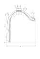
- FIG. 1 is a tire width direction partial cross-sectional view of a pneumatic tire according to one embodiment of the present invention. Although FIG. 1 shows only one half in the tire width direction bounded by the tire equatorial plane CL, the other half has the same configuration. Moreover, FIG. 1 is a tire width direction partial sectional view in the above reference state.
- this pneumatic tire (hereinafter simply referred to as a tire) 1 includes a pair of bead portions 2, a pair of sidewall portions 6 connected to the bead portions 2, and the pair of sidewall portions 6. and a tread portion 5 that continues to the tire
- the bead portion 2 has a bead core 2a and a bead filler 2b.
- the bead core 2a comprises a plurality of bead wires covered with rubber in this example.
- the bead wires are formed by steel cords in this example.
- the bead filler 2b is made of rubber or the like, and is positioned outside the bead core 2a in the tire radial direction.
- the bead filler 2b has a substantially triangular cross-sectional shape whose thickness decreases toward the outside in the tire radial direction.
- the bead core 2a and the bead filler 2b are not limited to the above examples, and can be configured in various ways.
- the tire 1 has a carcass 3 made up of one or more carcass plies that straddle a pair of bead portions 2 in a toroidal manner.
- the carcass 3 has a carcass body portion 3a arranged between the bead cores 2a, and a carcass folded portion 3b folded back from the inner side in the tire width direction to the outer side in the tire width direction around the bead cores 2a.
- the end of the carcass turned-up portion 3b is located inside the tire maximum width position in the tire radial direction. , can be set as appropriate.
- the carcass 3 may have a structure without the carcass turned-up portion 3b, or may have a structure in which the carcass turned-up portion 3b is wound around the bead core 2a.
- the carcass ply can be configured by coating organic fibers with rubber.
- a belt 4 and a tread rubber forming a tread portion 5 are provided outside the crown portion of the carcass 3 in the tire radial direction.
- the belt 4 can be configured by, for example, a plurality of belt layers laminated in the tire radial direction.
- the belt 4 is an inclined belt composed of two belt layers in which belt cords intersect each other between the layers. Steel cords, for example, can also be used as belt cords.
- the number of belt layers, the inclination angle of the belt cord, the width of each belt layer in the tire width direction, and the like are not particularly limited, and can be set as appropriate.
- the tire 1 has an inner liner (not shown) on the tire inner surface 8 .
- R be a tire radial region between positions spaced apart from the maximum tire width position P in the tire radial direction by 15% of the tire cross-sectional height SH to the tire radial direction inner side and outer side from the tire maximum width position P in the above reference state.
- the mass of the sidewall portion in the tire radial direction region R is 1.5% to 5% of the mass of the pneumatic tire 1 as a whole.
- the tire radial direction region R only in the tire radial direction region R
- the rubber member (rubber sheet in this example) 7 by attaching the rubber member (rubber sheet in this example) 7 to the sidewall portion surface, the above mass range is achieved. I'm trying The effects of the pneumatic tire of this embodiment will be described below.
- the present inventors have studied the phenomenon of noise generated by tire vibration, and found that the tire maximum width position and its vicinity are antinodes (parts where the amount of amplitude displacement increases) between 800 Hz and 1000 Hz. I got some insight. Then, the present inventors found that the tire diameter between positions spaced apart from the tire maximum width position P by 15% of the tire cross-section height SH inward and outward in the tire radial direction (0.15 ⁇ SH vertically in the figure) By locally increasing the mass in the directional region R, the amplitude of 800 Hz to 1000 Hz can be reduced to improve the quietness of the tire, and the increase in mass is localized to increase the tire weight as much as possible. I have found that it can be suppressed.
- the effect of reducing the amplitude of 800 Hz to 1000 Hz and improving the quietness of the tire cannot be sufficiently obtained. Further, if the mass of the sidewall portion in the tire radial direction region R is less than 1.5% of the mass of the entire pneumatic tire, the effect of suppressing vibration described above cannot be sufficiently exhibited, and the tire can not sufficiently improve the quietness of the On the other hand, if the mass of the sidewall portion in the tire radial direction region R exceeds 5% of the mass of the entire pneumatic tire, the weight in the vicinity of the tire maximum width position P becomes too large locally, resulting in weight loss.
- the mass of the sidewall portion in the tire radial direction region R is more preferably 1.8% to 4.5% of the mass of the entire pneumatic tire.
- the mass of the sidewall portion in the tire radial region R (10%) between the positions separated from the tire maximum width position P by 10% of the tire cross-sectional height inward and outward in the tire radial direction is the pneumatic More preferably, it is between 1.5% and 5% of the total mass of the tire. This is because the vibration can be more effectively reduced, and the quietness of the tire can be further improved. Also in this case, for the same reason, the mass of the sidewall portion in the tire radial direction region R (10%) is more preferably 1.8% to 4.5% of the mass of the entire pneumatic tire.
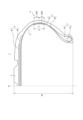
- FIG. 2 is a tire width direction partial cross-sectional view of a pneumatic tire according to a first modification.
- FIG. 3 is a tire width direction partial cross-sectional view of a pneumatic tire according to a second modification.
- a rubber member (rubber sheet) 7 can be attached to the inner surface 8 of the tire (if the tire has an inner liner, it may be inside or outside the inner liner). However, if the rubber member (rubber sheet) 7 is attached to the tire inner surface 8, the energy loss of the inner liner increases. It is more preferable to dispose it (inside the sidewall rubber).
- the rubber member is a rubber sheet, but the rubber member is not limited to a sheet-like rubber member, and may have various protruding shapes such as a semicircular cross-section or a rectangular cross-section. can be done.
- the thickness of the sidewall portion in the tire radial direction region R is preferably 1.0 to 4 mm thicker than the thickness of the thinnest portion of the sidewall portion.
- the thickness is 1.0 mm or more, the effect of suppressing the vibration described above can be further enhanced, and the quietness of the tire can be further improved. This is because it is possible to suppress the fact that the thickness of the tire becomes excessively large locally and the unevenness of the weight becomes large, and the tire flows or shifts when the tire is vulcanized.
- the "thickness of the sidewall portion” means the thickness measured in the direction perpendicular to the carcass line in the cross section in the tire width direction.
- the thickness of the sidewall portion in the tire radial direction region R (or R (10%)) is “1.0 to 4 mm thicker than the thickness of the thinnest portion of the sidewall portion” means that the tire It means that the average thickness of the sidewall portion in the radial region is “1.0 to 4 mm thicker than the thickness of the thinnest portion of the sidewall portion”.
- the convex part is formed in the said tire radial direction area
- the thickness of the sidewall portion in the tire radial direction region R (or R (10%)) is more preferably 1.5 to 4 mm thicker than the thickness of the thinnest portion of the sidewall portion. .
- the weight is preferably varied by changing the specific gravity of the material in the tire radial region R (or R(10%)). This is because the formation of localized weight-adding portions based only on the specific gravity reduces unevenness, thereby reducing structural stress-concentrating portions and improving the durability of the tire.
- the thickness of the sidewall portion at the tire maximum width position P can be 120% to 200% of the thickness of the thinnest portion of the sidewall portion. By making it 120% or more, the effect of suppressing the vibration described above can be further enhanced, and the quietness of the tire can be further improved. This is because it is possible to prevent the weight from becoming too large locally and the unevenness of the weight to increase, causing the tire to flow or shift during vulcanization.
- the thickness of the sidewall portion is preferably 5 mm to 15 mm. This is because a thickness of 5 mm or more can further enhance the effect of suppressing vibration and improving quietness, while a thickness of 15 mm or less can minimize an increase in weight.
- the specific gravity of the rubber member (eg, rubber sheet) 7 is preferably 1.05 times or more, more preferably 1.1 times or more, that of the sidewall rubber. This is because it is suitable for locally increasing weight.
- the specific gravity of the rubber member (for example, rubber sheet) 7 is preferably 1.3 times or less the specific gravity of the sidewall rubber in order to prevent the weight bias from becoming too large.
- the specific gravity can be adjusted, for example, by adjusting the blending amount of the filler.
- fillers that can be used include, but are not limited to, silica, aluminum hydroxide, calcium carbonate, basic magnesium carbonate, clay, diatomaceous earth, reclaimed and powdered rubber, and carbon black.
- the rubber member is arranged to locally increase the weight of the radial region R, but various other methods are possible.
- a weighting member made of metal or fiber (metallic fiber or non-metallic fiber).
- the metal and fiber may be composed of steel (a linear metal containing iron as the main component (the mass of iron exceeds 50% by mass with respect to the total mass of metal filaments)) or iron alone, or may be composed of other than iron.
- it may contain metals such as zinc, copper, aluminum, and tin. Examples include steel, copper, and alloys containing them. Plating may be performed to strengthen the adhesion to rubber.
- the rubber member is arranged in the tire radial direction region R, there is an advantage that durability against repeated deformation is high.
- the gauge of the tread rubber is preferably 2 to 30 mm, more preferably 2 to 15 mm. This is because a thickness of 2 mm or more can further enhance quietness, while a thickness of 30 mm or less can reduce rolling resistance due to weight reduction.
- the "tread rubber gauge” means, in the above reference state, the radially outermost reinforcing member (for example, the radially outermost belt layer of the tire) from the tread surface on the tire equatorial plane. When a belt reinforcing layer is arranged, it is the thickness in the tire radial direction up to the outermost belt reinforcing layer in the tire radial direction). However, when grooves are arranged on the tire equatorial plane, it is assumed that there are no grooves.
- the tire aspect ratio is preferably 20-80, more preferably 20-65, and even more preferably 35-55.
- the structure does not have a side reinforcing rubber.
- Example 1 In the tire radial direction region R of the tire having a tire size of 205/55R16, as shown in FIG. 1, three prototypes were made by adding mass at the maximum width position with different weights (Invention Examples 1 to 3). . Also, a conventional one was prepared in which no mass was added to the maximum width position (Comparative Example 1). In invention example 1, a mass of 55 g was added, in invention example 2, a mass of 105 g was added, and in invention example 3, a mass of 165 g was added. As a result, in invention examples 1, 2, and 3, the mass of the sidewall portion in the tire radial direction region R was 0.5%, 1%, and 2%, respectively, of the mass of the entire pneumatic tire. rice field. In invention examples 1, 2, and 3, the thickness of the sidewall portion in the tire radial direction region R was 0.5 mm, 1 mm, and 2 mm thicker than the thickness of the thinnest portion of the sidewall portion, respectively.
- Example 2 Next, the effect of the present invention was confirmed by changing the position where the weight is increased.
- Inventive Example 4 a tire having a mass of 130 g added to the maximum width position was manufactured.
- the mass of the sidewall portion in the tire radial direction region R was 1.1% of the mass of the entire pneumatic tire.
- the thickness of the sidewall portion in the tire radial direction region R was 1 mm thicker than the thickness of the thinnest portion of the sidewall portion.
- Comparative Example 2 a mass of 130 g was added to the surface of the sidewall portion in the region outside the tire radial direction region R in the tire radial direction.
- Comparative Example 3 a mass of 130 g was added to the surface of the sidewall portion in the region radially inward of the region R in the tire radial direction.
- a mass of 130 g was added over the entire sidewall portion.
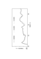
- Example 4 the amplitude of 800 Hz to 1000 Hz is reduced as compared with Comparative Examples 2 and 3.
- the amplitude of 800 Hz to 1000 Hz is reduced as compared with Comparative Example 4.
- the weight increase was 0.5%, 1%, and 2%, respectively, and an excessive weight increase was avoided.
- a rubber sheet corresponding to such a mass was attached, there was no occurrence of rubber flow or deviation during vulcanization.
Landscapes
- Engineering & Computer Science (AREA)
- Mechanical Engineering (AREA)
- Tires In General (AREA)
Abstract
Description
(1)空気入りタイヤであって、
前記空気入りタイヤを適用リムに装着し、規定内圧を充填し、無負荷とした状態を基準状態とするとき、
前記基準状態においてタイヤ最大幅位置からタイヤ径方向内側及び外側にタイヤ断面高さの15%ずつ離間した位置間のタイヤ径方向領域におけるサイドウォール部の質量が、前記空気入りタイヤの全体の質量の1.5%~5%であることを特徴とする、空気入りタイヤ。
以下、本実施形態の空気入りタイヤの作用効果について説明する。
また、上記タイヤ径方向領域Rにおけるサイドウォール部の質量が、空気入りタイヤの全体の質量の1.5%未満だと、上述した振動を抑制する効果を十分に発揮することができず、タイヤの静音性を十分に向上させることができない。一方で、上記タイヤ径方向領域Rにおけるサイドウォール部の質量が、空気入りタイヤの全体の質量の5%超だと、タイヤ最大幅位置P付近での重量が局所的に大きくなり過ぎて重量の偏りが大きくなり、タイヤを加硫する際に流れてしまったりずれてしまったりするおそれがある。同様の理由により、タイヤ径方向領域Rにおけるサイドウォール部の質量は、空気入りタイヤの全体の質量の1.8%~4.5%であることがより好ましい。
この場合も、同様の理由により、タイヤ径方向領域R(10%)におけるサイドウォール部の質量は、空気入りタイヤの全体の質量の1.8%~4.5%であることがより好ましい。
図1~図3では、ゴム部材がゴムシートである例を示したが、シート状のゴム部材には限定されず、断面半円状や断面矩形状の突出形状等、様々なものとすることができる。
ここで、「サイドウォール部の厚さ」とは、タイヤ幅方向断面において、カーカスラインに垂直な方向に計測した際の厚さを意味する。
また、当該タイヤ径方向領域R(またはR(10%))におけるサイドウォール部の厚さが、「サイドウォール部の最も薄い部分の厚さよりも、1.0~4mm厚い」とは、当該タイヤ径方向領域におけるサイドウォール部の厚さの平均が、「サイドウォール部の最も薄い部分の厚さよりも、1.0~4mm厚い」ことを意味する。なお、上記タイヤ径方向領域において凸部が形成されている場合は、その凸部の高さも含めて厚さとする。
また、タイヤ最大幅位置Pにおけるサイドウォール部の厚さが、サイドウォール部の最も薄い部分の厚さの120%~200%とすることもできる。120%以上とすることにより、上述した振動を抑制する効果をより一層高めて、タイヤの静音性をより一層向上させることができ、一方で、200%以下とすることにより、タイヤ最大幅位置Pでの重量が局所的に大きくなり過ぎて重量の偏りが大きくなり、タイヤを加硫する際に流れてしまったりずれてしまったりすることを抑制することができるからである。
なお、上記タイヤ径方向領域Rにゴム部材を配置している上記の実施形態によれば、繰り返し変形に対する耐久性が高いという利点がある。
「トレッドゴムのゲージ」とは、上記基準状態にて、タイヤ赤道面における、トレッド表面からタイヤ径方向最外側の補強部材(例えばタイヤ径方向最外側ベルト層であり、ベルトのタイヤ径方向外側にベルト補強層が配置されている場合は、タイヤ径方向最外側ベルト補強層)までのタイヤ径方向の厚さである。ただし、タイヤ赤道面に溝が配置されている場合は、溝が無いものと仮定して考えるものとする。
タイヤサイズ205/55R16のタイヤの上記タイヤ径方向領域Rにおいて、図1に示したように、最大幅位置に質量を付加したものを、重量を変えて3つ試作した(発明例1~3)。また、最大幅位置に質量を付加しない従来のものも用意した(比較例1)。発明例1では、質量55gを付加し、発明例2では、質量105gを付加し、発明例3では、質量165gを付加した。これにより、発明例1、2、3では、それぞれ、上記タイヤ径方向領域Rにおけるサイドウォール部の質量が、それぞれ、空気入りタイヤの全体の質量の0.5%、1%、2%となった。また、発明例1、2、3では、それぞれ、上記タイヤ径方向領域Rにおけるサイドウォール部の厚さが、サイドウォール部の最も薄い部分の厚さよりも0.5mm、1mm、2mm厚くなった。
次に、重量を増加させる位置を異ならせて、本発明の効果を確かめた。発明例4では、質量130gを最大幅位置に付加したタイヤを試作した。発明例4では、上記タイヤ径方向領域Rにおけるサイドウォール部の質量が、空気入りタイヤの全体の質量の1.1%となった。また、発明例4では、上記タイヤ径方向領域Rにおけるサイドウォール部の厚さが、サイドウォール部の最も薄い部分の厚さよりも1mm厚くなった。また、比較例2では、タイヤ径方向領域Rよりもタイヤ径方向外側の領域において、サイドウォール部の表面に質量130gを付加した。また、比較例3では、タイヤ径方向領域Rよりもタイヤ径方向内側の領域において、サイドウォール部の表面に質量130gを付加した。比較例4では、サイドウォール部全体にわたるように質量130gを付加した。
また、図6に示すように、発明例4では、比較例4に対して、800Hz~1000Hzの振幅が低減していることがわかる。
2:ビード部、
3:カーカス、
4:ベルト、
5:トレッド部、
6:サイドウォール部、
7:ゴム部材、
8:タイヤ内面
Claims (5)
- 空気入りタイヤであって、
前記空気入りタイヤを適用リムに装着し、規定内圧を充填し、無負荷とした状態を基準状態とするとき、
前記基準状態においてタイヤ最大幅位置からタイヤ径方向内側及び外側にタイヤ断面高さの15%ずつ離間した位置間のタイヤ径方向領域におけるサイドウォール部の質量が、前記空気入りタイヤの全体の質量の1.5%~5%であることを特徴とする、空気入りタイヤ。 - 前記基準状態においてタイヤ最大幅位置からタイヤ径方向内側及び外側にタイヤ断面高さの10%ずつ離間した位置間のタイヤ径方向領域における、サイドウォール部の質量が、前記空気入りタイヤの全体の質量の1.5%~5%である、請求項1に記載の空気入りタイヤ。
- 前記タイヤ径方向領域に、ゴム部材が配置されている、請求項1又は2に記載の空気入りタイヤ。
- 前記ゴム部材の比重は、サイドウォールゴムの比重の1.05倍以上である、請求項3に記載の空気入りタイヤ。
- 前記タイヤ径方向領域において、金属又は繊維からなる加重部材を有する、請求項1又は2に記載の空気入りタイヤ。
Priority Applications (3)
| Application Number | Priority Date | Filing Date | Title |
|---|---|---|---|
| EP22898155.1A EP4438343A4 (en) | 2021-11-25 | 2022-06-23 | PNEUMATIC TIRES |
| CN202280074704.6A CN118354915A (zh) | 2021-11-25 | 2022-06-23 | 充气轮胎 |
| US18/699,890 US20240408921A1 (en) | 2021-11-25 | 2022-06-23 | Pneumatic tire |
Applications Claiming Priority (2)
| Application Number | Priority Date | Filing Date | Title |
|---|---|---|---|
| JP2021-191545 | 2021-11-25 | ||
| JP2021191545A JP7690384B2 (ja) | 2021-11-25 | 2021-11-25 | 空気入りタイヤ |
Publications (1)
| Publication Number | Publication Date |
|---|---|
| WO2023095370A1 true WO2023095370A1 (ja) | 2023-06-01 |
Family
ID=86539014
Family Applications (1)
| Application Number | Title | Priority Date | Filing Date |
|---|---|---|---|
| PCT/JP2022/025154 Ceased WO2023095370A1 (ja) | 2021-11-25 | 2022-06-23 | 空気入りタイヤ |
Country Status (5)
| Country | Link |
|---|---|
| US (1) | US20240408921A1 (ja) |
| EP (1) | EP4438343A4 (ja) |
| JP (1) | JP7690384B2 (ja) |
| CN (1) | CN118354915A (ja) |
| WO (1) | WO2023095370A1 (ja) |
Citations (7)
| Publication number | Priority date | Publication date | Assignee | Title |
|---|---|---|---|---|
| JPH0443107A (ja) * | 1990-06-07 | 1992-02-13 | Bridgestone Corp | 空気入りタイヤ |
| JPH071924A (ja) * | 1993-03-08 | 1995-01-06 | Sumitomo Rubber Ind Ltd | 空気入りラジアルタイヤ |
| JPH10250321A (ja) * | 1997-03-12 | 1998-09-22 | Bridgestone Corp | 空気入りラジアルタイヤ |
| JPH11124471A (ja) * | 1997-10-23 | 1999-05-11 | Yokohama Rubber Co Ltd:The | 空気入りタイヤ |
| JP2001047819A (ja) * | 1999-08-03 | 2001-02-20 | Toyo Tire & Rubber Co Ltd | 空気入りタイヤ |
| JP2002103924A (ja) * | 2000-10-03 | 2002-04-09 | Bridgestone Corp | 空気入りラジアルタイヤ |
| WO2006003742A1 (ja) * | 2004-06-30 | 2006-01-12 | Bridgestone Corporation | 空気入りタイヤ |
Family Cites Families (10)
| Publication number | Priority date | Publication date | Assignee | Title |
|---|---|---|---|---|
| EP0614774B1 (en) * | 1993-03-08 | 1997-05-14 | Sumitomo Rubber Industries Limited | Pneumatic radial tyre |
| US5871599A (en) * | 1995-08-24 | 1999-02-16 | Bridgestone Corporation | Low-noise pneumatic tires with specified carcass line |
| JP2000177312A (ja) * | 1998-12-14 | 2000-06-27 | Bridgestone Corp | 空気入りラジアルタイヤ |
| FR2812240A1 (fr) * | 2000-07-31 | 2002-02-01 | Michelin Soc Tech | Pneumatique avec des flancs de structure amelioree |
| JP4575607B2 (ja) * | 2000-10-03 | 2010-11-04 | 不二精工株式会社 | ランフラットタイヤ及びランフラットタイヤとリムとの組立体 |
| JP2011057068A (ja) * | 2009-09-09 | 2011-03-24 | Yokohama Rubber Co Ltd:The | 空気入りタイヤ |
| DE112011105656B4 (de) * | 2011-09-22 | 2016-02-18 | The Yokohama Rubber Co., Ltd. | Luftreifen |
| JP5548793B1 (ja) * | 2013-02-28 | 2014-07-16 | 株式会社ブリヂストン | 乗用車用空気入りラジアルタイヤ |
| JP6779780B2 (ja) * | 2016-12-28 | 2020-11-04 | Toyo Tire株式会社 | 空気入りタイヤ |
| WO2019035281A1 (ja) * | 2017-08-18 | 2019-02-21 | 横浜ゴム株式会社 | 空気入りタイヤ |
-
2021
- 2021-11-25 JP JP2021191545A patent/JP7690384B2/ja active Active
-
2022
- 2022-06-23 CN CN202280074704.6A patent/CN118354915A/zh active Pending
- 2022-06-23 EP EP22898155.1A patent/EP4438343A4/en not_active Withdrawn
- 2022-06-23 US US18/699,890 patent/US20240408921A1/en active Pending
- 2022-06-23 WO PCT/JP2022/025154 patent/WO2023095370A1/ja not_active Ceased
Patent Citations (7)
| Publication number | Priority date | Publication date | Assignee | Title |
|---|---|---|---|---|
| JPH0443107A (ja) * | 1990-06-07 | 1992-02-13 | Bridgestone Corp | 空気入りタイヤ |
| JPH071924A (ja) * | 1993-03-08 | 1995-01-06 | Sumitomo Rubber Ind Ltd | 空気入りラジアルタイヤ |
| JPH10250321A (ja) * | 1997-03-12 | 1998-09-22 | Bridgestone Corp | 空気入りラジアルタイヤ |
| JPH11124471A (ja) * | 1997-10-23 | 1999-05-11 | Yokohama Rubber Co Ltd:The | 空気入りタイヤ |
| JP2001047819A (ja) * | 1999-08-03 | 2001-02-20 | Toyo Tire & Rubber Co Ltd | 空気入りタイヤ |
| JP2002103924A (ja) * | 2000-10-03 | 2002-04-09 | Bridgestone Corp | 空気入りラジアルタイヤ |
| WO2006003742A1 (ja) * | 2004-06-30 | 2006-01-12 | Bridgestone Corporation | 空気入りタイヤ |
Non-Patent Citations (1)
| Title |
|---|
| "FUTURE DEVELOPMENTS", 2013, ETRTO |
Also Published As
| Publication number | Publication date |
|---|---|
| JP7690384B2 (ja) | 2025-06-10 |
| EP4438343A4 (en) | 2025-03-05 |
| CN118354915A (zh) | 2024-07-16 |
| US20240408921A1 (en) | 2024-12-12 |
| JP2023078000A (ja) | 2023-06-06 |
| EP4438343A1 (en) | 2024-10-02 |
Similar Documents
| Publication | Publication Date | Title |
|---|---|---|
| JP6546322B2 (ja) | 乗用車用空気入りラジアルタイヤ及びその使用方法 | |
| JP5041104B1 (ja) | 空気入りタイヤ | |
| US20120318427A1 (en) | Pneumatic radial tire | |
| JP4973810B1 (ja) | 空気入りタイヤ | |
| JP5750156B2 (ja) | 空気入りタイヤ | |
| JP4500117B2 (ja) | 重荷重用空気入りラジアルタイヤ | |
| JP2017222209A (ja) | 空気入りタイヤ | |
| JPWO2015063977A1 (ja) | タイヤ | |
| WO2015159468A1 (ja) | ランフラットタイヤ | |
| JP2010006322A (ja) | 空気入りタイヤ | |
| JP4487570B2 (ja) | 空気入りラジアルタイヤ | |
| JP6300342B2 (ja) | ランフラットタイヤ | |
| JPH05155208A (ja) | 重荷重用空気入りラジアルタイヤ | |
| WO2023095370A1 (ja) | 空気入りタイヤ | |
| WO2023095371A1 (ja) | 空気入りタイヤ | |
| JP2012116382A (ja) | ランフラットタイヤ | |
| US11364751B2 (en) | Pneumatic tire | |
| JP5598262B2 (ja) | 空気入りタイヤ | |
| JP4842628B2 (ja) | 重荷重用空気入りラジアルタイヤ | |
| JP2009269504A (ja) | 空気入りタイヤ | |
| JP2022120448A (ja) | タイヤ | |
| WO2016024390A1 (ja) | 空気入りタイヤ | |
| JP5772254B2 (ja) | 空気入りタイヤ | |
| JP5823795B2 (ja) | 重荷重用空気入りラジアルタイヤ | |
| JP4577005B2 (ja) | 小型トラック用空気入りタイヤ |
Legal Events
| Date | Code | Title | Description |
|---|---|---|---|
| 121 | Ep: the epo has been informed by wipo that ep was designated in this application |
Ref document number: 22898155 Country of ref document: EP Kind code of ref document: A1 |
|
| WWE | Wipo information: entry into national phase |
Ref document number: 202280074704.6 Country of ref document: CN |
|
| WWE | Wipo information: entry into national phase |
Ref document number: 2022898155 Country of ref document: EP |
|
| NENP | Non-entry into the national phase |
Ref country code: DE |
|
| ENP | Entry into the national phase |
Ref document number: 2022898155 Country of ref document: EP Effective date: 20240625 |
|
| WWW | Wipo information: withdrawn in national office |
Ref document number: 2022898155 Country of ref document: EP |