WO2023095481A1 - ガイドワイヤ - Google Patents
ガイドワイヤ Download PDFInfo
- Publication number
- WO2023095481A1 WO2023095481A1 PCT/JP2022/038325 JP2022038325W WO2023095481A1 WO 2023095481 A1 WO2023095481 A1 WO 2023095481A1 JP 2022038325 W JP2022038325 W JP 2022038325W WO 2023095481 A1 WO2023095481 A1 WO 2023095481A1
- Authority
- WO
- WIPO (PCT)
- Prior art keywords
- tip
- core shaft
- coil
- guide wire
- wire
- Prior art date
- Legal status (The legal status is an assumption and is not a legal conclusion. Google has not performed a legal analysis and makes no representation as to the accuracy of the status listed.)
- Ceased
Links
Images

Classifications
-
- A—HUMAN NECESSITIES
- A61—MEDICAL OR VETERINARY SCIENCE; HYGIENE
- A61M—DEVICES FOR INTRODUCING MEDIA INTO, OR ONTO, THE BODY; DEVICES FOR TRANSDUCING BODY MEDIA OR FOR TAKING MEDIA FROM THE BODY; DEVICES FOR PRODUCING OR ENDING SLEEP OR STUPOR
- A61M25/00—Catheters; Hollow probes
- A61M25/01—Introducing, guiding, advancing, emplacing or holding catheters
- A61M25/0105—Steering means as part of the catheter or advancing means; Markers for positioning
- A61M25/0108—Steering means as part of the catheter or advancing means; Markers for positioning using radio-opaque or ultrasound markers
-
- A—HUMAN NECESSITIES
- A61—MEDICAL OR VETERINARY SCIENCE; HYGIENE
- A61M—DEVICES FOR INTRODUCING MEDIA INTO, OR ONTO, THE BODY; DEVICES FOR TRANSDUCING BODY MEDIA OR FOR TAKING MEDIA FROM THE BODY; DEVICES FOR PRODUCING OR ENDING SLEEP OR STUPOR
- A61M25/00—Catheters; Hollow probes
- A61M25/01—Introducing, guiding, advancing, emplacing or holding catheters
- A61M25/09—Guide wires
-
- A—HUMAN NECESSITIES
- A61—MEDICAL OR VETERINARY SCIENCE; HYGIENE
- A61M—DEVICES FOR INTRODUCING MEDIA INTO, OR ONTO, THE BODY; DEVICES FOR TRANSDUCING BODY MEDIA OR FOR TAKING MEDIA FROM THE BODY; DEVICES FOR PRODUCING OR ENDING SLEEP OR STUPOR
- A61M25/00—Catheters; Hollow probes
- A61M25/01—Introducing, guiding, advancing, emplacing or holding catheters
- A61M25/09—Guide wires
- A61M2025/09058—Basic structures of guide wires
- A61M2025/09083—Basic structures of guide wires having a coil around a core
-
- A—HUMAN NECESSITIES
- A61—MEDICAL OR VETERINARY SCIENCE; HYGIENE
- A61M—DEVICES FOR INTRODUCING MEDIA INTO, OR ONTO, THE BODY; DEVICES FOR TRANSDUCING BODY MEDIA OR FOR TAKING MEDIA FROM THE BODY; DEVICES FOR PRODUCING OR ENDING SLEEP OR STUPOR
- A61M25/00—Catheters; Hollow probes
- A61M25/01—Introducing, guiding, advancing, emplacing or holding catheters
- A61M25/09—Guide wires
- A61M2025/09166—Guide wires having radio-opaque features
-
- A—HUMAN NECESSITIES
- A61—MEDICAL OR VETERINARY SCIENCE; HYGIENE
- A61M—DEVICES FOR INTRODUCING MEDIA INTO, OR ONTO, THE BODY; DEVICES FOR TRANSDUCING BODY MEDIA OR FOR TAKING MEDIA FROM THE BODY; DEVICES FOR PRODUCING OR ENDING SLEEP OR STUPOR
- A61M25/00—Catheters; Hollow probes
- A61M25/01—Introducing, guiding, advancing, emplacing or holding catheters
- A61M25/09—Guide wires
- A61M2025/09175—Guide wires having specific characteristics at the distal tip
Definitions
- the present invention relates to guidewires.
- therapeutic instruments such as balloon catheters.
- a guide wire is inserted into the blood vessel to guide them in advance.
- the present disclosure has been made based on the circumstances as described above, and its purpose is to provide a guide wire capable of improving the visibility of the distal end during X-ray irradiation.
- a guidewire includes a core shaft, a coil made of a wire spirally wound so as to cover the outer circumference of the core shaft, and a tip end of the core shaft. and a tip joint joining the tip of the coil, the tip joint having a dispersion in which a radiopaque first material is dispersed.
- the tip junction may have a high-concentration region in which the concentration of the first material is relatively high.
- the high-concentration region may be located on the rear end side of the tip junction.
- the core shaft is made of a second material that is different from the first material
- the coil is made of the first material
- the tip joint portion includes a tip portion of the core shaft and a tip portion of the coil. It may be formed by melting and bonding.
- the wire in the tip joint portion may have a convex portion.
- the present invention can provide a guide wire that can improve the visibility of the distal end during X-ray irradiation.
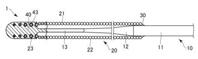
- FIG. 1 is a schematic partial cross-sectional view of a guidewire according to an embodiment
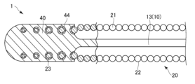
- FIG. FIG. 2 is an enlarged partial cross-sectional view of the vicinity of the tip joint portion of the guide wire in FIG. 1
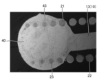
- Fig. 3 is an image of a longitudinal section of the tip joint
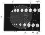
- It is an elemental mapping image of the longitudinal section of the tip joint.
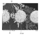
- FIG. 4 is an explanatory diagram of the tip of the tip junction and the high-concentration region; It is an elemental mapping image of the vertical cross section of the tip joint, and is an elemental mapping image in which the wire is enlarged.
- the distal end means the end of the guidewire where the distal junction is located, and the posterior end means the end opposite to the distal end.
- FIG. 1 is a schematic partial cross-sectional view of a guidewire 1 according to an embodiment.
- FIG. 2 is an enlarged partial cross-sectional view of the vicinity of the tip junction of the guide wire 1.
- FIG. FIG. 1 shows only a part of the guide wire 1 on the distal side.
- the guidewire 1 comprises a core shaft 10 , a coil 20 , a proximal junction 30 and a distal junction 40 .
- the core shaft 10 has a core shaft main body 11 , a tapered portion 12 and a tip portion 13 .
- the tapered portion 12 extends continuously from the core shaft body 11 toward the distal end while decreasing in diameter.
- the tip portion 13 extends continuously from the tapered portion 12 toward the tip.
- the core shaft body 11 extends toward the rear end side, and the user can rotate the guide wire 1 at the rear end side of the core shaft body 11 . done.
- Examples of materials forming the core shaft 10 include stainless steel such as SUS302, SUS304, and SUS316.
- the coil 20 is provided so as to cover the tip of the core shaft body 11, the tapered portion 12, and the outer periphery of the tip portion 13.
- the coil 20 is formed in a hollow cylindrical shape by spirally winding a wire 21 made of, for example, tungsten around the core shaft 10 .
- the coil 20 has a rear end portion 22 and a front end portion 23 .
- the rear end portion 22 is wound so that the wire 21 abuts thereon in the axial direction.
- the tip portion 23 is wound so that the wire 21 has a gap in the axial direction.
- the front end portion 23 is configured to have a smaller outer diameter than the rear end portion 22 .
- the tip portion 23 is included in the tip joint portion 30 .
- Examples of the material forming the coil 20 include X-ray opaque tungsten. Tungsten, which constitutes the coil 20, is the radiopaque first material.
- the stainless steel forming the core shaft 10 is a second material different from the first material.
- a proximal end of the coil 20 is joined to the core shaft 10 by a proximal joint portion 30 .
- the material forming the base end joint portion 30 include solder metal such as Sn--Pb alloy, Pb--Ag alloy, Sn--Ag alloy and Au--Sn alloy, and adhesive such as epoxy resin.
- FIG. 3 is a longitudinal cross-sectional image of the tip joint 40 .
- FIG. 4 is an elemental mapping image of a longitudinal section of the tip joint 40.
- FIG. 5 is an explanatory diagram of the tip portion 42 and the high-concentration region 43 of the tip junction portion 40 .
- FIG. 6 is an elemental mapping image of a longitudinal section of the tip joint portion 40, which is an enlarged elemental mapping image of the wire 21.
- the outlines of the tip joint portion 40 and the tip portion 13 of the core shaft 10 are indicated by white dotted lines.
- 4 to 6 are elemental mapping images of longitudinal cross sections of the tip joint 40 obtained using EDX (Energy Dispersive X-ray Spectroscopy).
- the tip joint 40 joins the tip of the tip 13 of the core shaft 10 and the tip 23 of the coil 20 .
- the tip joint portion 40 includes the tip portion 23 of the coil 20 .
- the diameter of the wire 21 at the tip portion 23 decreases toward the tip.
- the tip of the tip portion 23 is located near the tip of the tip joint portion 40 .
- the tip joint portion 40 is formed by melting a portion of the core shaft 10 that was originally located on the tip side of the tip portion 13 and a part of the wire 21 of the tip portion 23 by arc welding such as plasma welding. It is
- the black portion of the tip joint portion 40 is a material other than the first material such as stainless steel, and the gray or white portion is the first material such as tungsten.
- the tip joint portion 40 includes a dispersed portion 42 which is a portion in which a first material having radiopacity is dispersed substantially uniformly within a certain range, and a high concentration of the first material higher than that of the dispersed portion 42 . It has a region 43 .
- the portion excluding the wire 21 in the area surrounded by the dotted line is the dispersed portion 42
- the portion excluding the wire 21 in the area surrounded by the dashed line is This is the high-concentration region 43 .
- the high-concentration region 43 exists on the rear end side of the tip junction portion 40 .
- the dispersed portion 42 is a portion in which the radiopaque first material (tungsten) is dispersed substantially uniformly within a certain range.
- tungsten is distributed substantially uniformly within a certain range.
- the dispersed portion 42 is, for example, a portion in which the molar ratio (%) of tungsten per unit area (1 ⁇ m 2 ) in the tip joint portion 40 is greater than 0% and less than 13.3%.
- the concentration of the first material in the dispersed portion 42 is relatively low compared to the high concentration region 43 .
- the distributed portion 42 exists so as to spread over the entire distal end side in the distal joint portion 40 . As a result, the entire distal end side of the distal joint portion 40 can be visually recognized under X-ray fluoroscopy.
- the high-concentration region 43 is a portion where the concentration of the radiopaque first material is relatively high compared to the dispersed portion 42 .
- the high-concentration region 43 is, for example, a portion where the molar ratio (%) of tungsten per unit area (1 ⁇ m 2 ) is 13.3% or more. Dense region 43 may be at any portion of tip junction 40 .
- the high-concentration region 43 exists at the tip of the tip joint portion 40, the visibility of the tip of the tip joint portion 40 under X-ray fluoroscopy is improved.
- the high concentration region 43 exists at the rear end of the tip joint portion 40, the visibility of the boundary portion between the tip joint portion 40 and the core shaft 10 under X-ray fluoroscopy is improved.
- a dendritic phase 44 made of tungsten and extending outward from the wire 21 in a dendritic manner exists around the wire 21 .
- the dendritic phase 44 exists so as to spread radially on the outer circumference of the wire 21 . That is, the wire 21 in the tip joint portion 40 has a convex portion on its outer circumference.
- part of the wire 21 made of tungsten is melted by arc welding during its formation, and the molten tungsten forms the dispersed portion 42 and the high-concentration region 43 in the tip joint 40, and , distributed around the wire 21 as a dendritic phase 44 .
- the guide wire 1 is inserted into the femoral blood vessel from the distal joint 40 and advanced along the blood vessel to the coronary artery.
- a therapeutic instrument such as a balloon catheter or a stent is transported along the guidewire 1, and various treatments are performed at the treatment site. do.
- the guidewire 1 is withdrawn from the body retrograde the blood vessel, completing the series of operations. The position of the distal end of the guide wire 1 inside the blood vessel is confirmed with an X-ray fluoroscopic image.
- the core shaft 10 the coil 20 made of a wire spirally wound so as to cover the outer circumference of the core shaft 10, the tip of the core shaft 10 and the tip 23 of the coil 20 a tip joint 40 that joins the tip joint 40 having a dispersion 42 in which radiopaque tungsten is dispersed.
- the visibility of the distal joint portion 40 which is the distal end portion of the guide wire 1, during X-ray irradiation can be improved.
- the tip junction 40 has a high-concentration region 43 in which the concentration of tungsten is relatively high. As a result, the visibility of the distal joint portion 40, which is the distal end portion of the guide wire 1, during X-ray irradiation can be further improved.
- the high-concentration region 43 is located on the rear end side of the tip joint portion 40 .
- the visibility of the rear end of the distal joint portion 40 (the distal end of the distal end portion 13), which is the distal end portion of the guide wire 1 during X-ray irradiation, can be further improved.
- the core shaft 10 is made of stainless steel different from tungsten
- the coil 20 is made of tungsten
- the tip joint portion 40 melts and joins the tip portion 13 of the core shaft 10 and the tip portion 23 of the coil 20. It is formed by Thus, by melting the core shaft 10 and the coil 20 to integrally form the tip joint portion 40, the joint strength between the core shaft 10 and the coil 20 can be further improved.
- the joint strength between the core shaft 10 and the coil 20 can be further improved.
- the coil 20 is composed of one wire 21, but may be composed of a plurality of wires.
- the dispersion section 42 was constructed of tungsten as the first radiopaque material and stainless steel as the second radiopaque material.
- the first material having X-ray opacity is a material capable of forming a tip joint portion having dispersed portions that are substantially uniformly dispersed within a certain range of the second material that easily transmits X-rays. , other X-ray transparent materials and radiopaque materials.
Landscapes
- Health & Medical Sciences (AREA)
- Life Sciences & Earth Sciences (AREA)
- Biophysics (AREA)
- Pulmonology (AREA)
- Engineering & Computer Science (AREA)
- Anesthesiology (AREA)
- Biomedical Technology (AREA)
- Heart & Thoracic Surgery (AREA)
- Hematology (AREA)
- Animal Behavior & Ethology (AREA)
- General Health & Medical Sciences (AREA)
- Public Health (AREA)
- Veterinary Medicine (AREA)
- Media Introduction/Drainage Providing Device (AREA)
Abstract
Description
ガイドワイヤ1は、コアシャフト10と、コイル20と、基端接合部30と、先端接合部40とを備える。
10 コアシャフト
20 コイル
23 先端部
40 先端接合部
42 分散部
43 高濃度領域
44 樹枝状相
Claims (5)
- コアシャフトと、
前記コアシャフトの外周を覆うように螺旋状に巻かれた素線からなるコイルと、
前記コアシャフトの先端と前記コイルの先端とを接合する先端接合部と、を備え、
前記先端接合部は、X線不透過性の第1材料が分散する分散部を有する、ガイドワイヤ。 - 前記先端接合部は、前記第1材料の濃度が相対的に高い高濃度領域を有する、請求項1に記載のガイドワイヤ。
- 前記高濃度領域は、前記先端接合部の後端側に位置している、請求項2に記載のガイドワイヤ。
- 前記コアシャフトは、前記第1材料と異なる第2材料からなり、
前記コイルは、前記第1材料からなり、
前記先端接合部は、前記コアシャフトの先端部と、前記コイルの先端部と、を溶融して接合することにより形成される、請求項1から請求項3のいずれか一項に記載のガイドワイヤ。 - 前記先端接合部内の前記素線は凸部を有している、請求項1から請求項4のいずれか一項に記載のガイドワイヤ。
Priority Applications (3)
| Application Number | Priority Date | Filing Date | Title |
|---|---|---|---|
| CN202280077769.6A CN118302221A (zh) | 2021-11-26 | 2022-10-14 | 导丝 |
| EP22898265.8A EP4438099B1 (en) | 2021-11-26 | 2022-10-14 | Guide wire |
| US18/665,247 US20240299711A1 (en) | 2021-11-26 | 2024-05-15 | Guide wire |
Applications Claiming Priority (2)
| Application Number | Priority Date | Filing Date | Title |
|---|---|---|---|
| JP2021-192234 | 2021-11-26 | ||
| JP2021192234A JP7749426B2 (ja) | 2021-11-26 | 2021-11-26 | ガイドワイヤ |
Related Child Applications (1)
| Application Number | Title | Priority Date | Filing Date |
|---|---|---|---|
| US18/665,247 Continuation US20240299711A1 (en) | 2021-11-26 | 2024-05-15 | Guide wire |
Publications (1)
| Publication Number | Publication Date |
|---|---|
| WO2023095481A1 true WO2023095481A1 (ja) | 2023-06-01 |
Family
ID=86539216
Family Applications (1)
| Application Number | Title | Priority Date | Filing Date |
|---|---|---|---|
| PCT/JP2022/038325 Ceased WO2023095481A1 (ja) | 2021-11-26 | 2022-10-14 | ガイドワイヤ |
Country Status (5)
| Country | Link |
|---|---|
| US (1) | US20240299711A1 (ja) |
| EP (1) | EP4438099B1 (ja) |
| JP (1) | JP7749426B2 (ja) |
| CN (1) | CN118302221A (ja) |
| WO (1) | WO2023095481A1 (ja) |
Citations (5)
| Publication number | Priority date | Publication date | Assignee | Title |
|---|---|---|---|---|
| US4634042A (en) | 1984-04-10 | 1987-01-06 | Cordis Corporation | Method of joining refractory metals to lower melting dissimilar metals |
| US5488959A (en) * | 1993-12-27 | 1996-02-06 | Cordis Corporation | Medical guidewire and welding process |
| JP2007044388A (ja) * | 2005-08-12 | 2007-02-22 | Fmd:Kk | 医療用ガイドワイヤ及びその製造方法 |
| JP2014161705A (ja) * | 2013-02-28 | 2014-09-08 | Asahi Intecc Co Ltd | ガイドワイヤ |
| WO2020219457A1 (en) * | 2019-04-25 | 2020-10-29 | Opsens, Inc. | Guidewire with internal pressure sensor |
Family Cites Families (1)
| Publication number | Priority date | Publication date | Assignee | Title |
|---|---|---|---|---|
| WO1991000051A1 (en) * | 1989-06-28 | 1991-01-10 | Boston Scientific Corporation | Steerable highly elongated guidewire |
-
2021
- 2021-11-26 JP JP2021192234A patent/JP7749426B2/ja active Active
-
2022
- 2022-10-14 WO PCT/JP2022/038325 patent/WO2023095481A1/ja not_active Ceased
- 2022-10-14 CN CN202280077769.6A patent/CN118302221A/zh active Pending
- 2022-10-14 EP EP22898265.8A patent/EP4438099B1/en active Active
-
2024
- 2024-05-15 US US18/665,247 patent/US20240299711A1/en active Pending
Patent Citations (5)
| Publication number | Priority date | Publication date | Assignee | Title |
|---|---|---|---|---|
| US4634042A (en) | 1984-04-10 | 1987-01-06 | Cordis Corporation | Method of joining refractory metals to lower melting dissimilar metals |
| US5488959A (en) * | 1993-12-27 | 1996-02-06 | Cordis Corporation | Medical guidewire and welding process |
| JP2007044388A (ja) * | 2005-08-12 | 2007-02-22 | Fmd:Kk | 医療用ガイドワイヤ及びその製造方法 |
| JP2014161705A (ja) * | 2013-02-28 | 2014-09-08 | Asahi Intecc Co Ltd | ガイドワイヤ |
| WO2020219457A1 (en) * | 2019-04-25 | 2020-10-29 | Opsens, Inc. | Guidewire with internal pressure sensor |
Non-Patent Citations (1)
| Title |
|---|
| See also references of EP4438099A4 |
Also Published As
| Publication number | Publication date |
|---|---|
| US20240299711A1 (en) | 2024-09-12 |
| EP4438099B1 (en) | 2026-04-08 |
| JP7749426B2 (ja) | 2025-10-06 |
| JP2023078906A (ja) | 2023-06-07 |
| CN118302221A (zh) | 2024-07-05 |
| EP4438099A1 (en) | 2024-10-02 |
| EP4438099A4 (en) | 2025-11-12 |
Similar Documents
| Publication | Publication Date | Title |
|---|---|---|
| US5673707A (en) | Enhanced performance guidewire | |
| JP5954748B2 (ja) | カテーテル | |
| JP2902076B2 (ja) | ガイドワイヤー | |
| US8480598B2 (en) | Guide wire with soldered multilayer coil member | |
| US20120271232A1 (en) | Catheter | |
| JPH10513081A (ja) | バイメタルコイルを備えたガイドワイヤ | |
| JPH06327775A (ja) | ガイドワイヤ | |
| US20200086089A1 (en) | Systems, methods and apparatus for guiding and supporting catheters such as stent delivery catheters | |
| US11701497B2 (en) | Guide wire | |
| JP4497746B2 (ja) | ガイドワイヤ | |
| JP3080483B2 (ja) | 医療用ガイドワイヤ及びそのコイルの製造方法 | |
| JP7749426B2 (ja) | ガイドワイヤ | |
| JP6724251B2 (ja) | プラズマ用ガイドワイヤ | |
| US11420028B2 (en) | Guide wire | |
| JP7538865B2 (ja) | ガイドワイヤ | |
| JP7644808B2 (ja) | ガイドワイヤ | |
| US20230181879A1 (en) | Guide wire | |
| JP6864110B2 (ja) | ガイドワイヤ | |
| EP3744379B1 (en) | Catheter | |
| US20220105310A1 (en) | Hollow shaft and catheter | |
| JP2024037226A (ja) | カテーテル | |
| JP3091328B2 (ja) | 医療用ガイドワイヤ | |
| JP2011056148A (ja) | バルーンカテーテル | |
| WO2022270437A1 (ja) | ガイドワイヤ | |
| JP2026055190A (ja) | 医療デバイスの製造方法、および、医療デバイス |
Legal Events
| Date | Code | Title | Description |
|---|---|---|---|
| 121 | Ep: the epo has been informed by wipo that ep was designated in this application |
Ref document number: 22898265 Country of ref document: EP Kind code of ref document: A1 |
|
| WWE | Wipo information: entry into national phase |
Ref document number: 202280077769.6 Country of ref document: CN |
|
| WWE | Wipo information: entry into national phase |
Ref document number: 2022898265 Country of ref document: EP |
|
| NENP | Non-entry into the national phase |
Ref country code: DE |
|
| ENP | Entry into the national phase |
Ref document number: 2022898265 Country of ref document: EP Effective date: 20240626 |
|
| WWG | Wipo information: grant in national office |
Ref document number: 2022898265 Country of ref document: EP |