WO2023099533A1 - Turbomachine axiale triple-flux avec échangeur de chaleur divergeant dans le troisième flux - Google Patents
Turbomachine axiale triple-flux avec échangeur de chaleur divergeant dans le troisième flux Download PDFInfo
- Publication number
- WO2023099533A1 WO2023099533A1 PCT/EP2022/083790 EP2022083790W WO2023099533A1 WO 2023099533 A1 WO2023099533 A1 WO 2023099533A1 EP 2022083790 W EP2022083790 W EP 2022083790W WO 2023099533 A1 WO2023099533 A1 WO 2023099533A1
- Authority
- WO
- WIPO (PCT)
- Prior art keywords
- oil
- heat exchanger
- flow
- wall
- air
- Prior art date
- Legal status (The legal status is an assumption and is not a legal conclusion. Google has not performed a legal analysis and makes no representation as to the accuracy of the status listed.)
- Ceased
Links
Images


Classifications
-
- F—MECHANICAL ENGINEERING; LIGHTING; HEATING; WEAPONS; BLASTING
- F02—COMBUSTION ENGINES; HOT-GAS OR COMBUSTION-PRODUCT ENGINE PLANTS
- F02C—GAS-TURBINE PLANTS; AIR INTAKES FOR JET-PROPULSION PLANTS; CONTROLLING FUEL SUPPLY IN AIR-BREATHING JET-PROPULSION PLANTS
- F02C3/00—Gas-turbine plants characterised by the use of combustion products as the working fluid
- F02C3/04—Gas-turbine plants characterised by the use of combustion products as the working fluid having a turbine driving a compressor
- F02C3/06—Gas-turbine plants characterised by the use of combustion products as the working fluid having a turbine driving a compressor the compressor comprising only axial stages
-
- F—MECHANICAL ENGINEERING; LIGHTING; HEATING; WEAPONS; BLASTING
- F28—HEAT EXCHANGE IN GENERAL
- F28D—HEAT-EXCHANGE APPARATUS, NOT PROVIDED FOR IN ANOTHER SUBCLASS, IN WHICH THE HEAT-EXCHANGE MEDIA DO NOT COME INTO DIRECT CONTACT
- F28D7/00—Heat-exchange apparatus having stationary tubular conduit assemblies for both heat-exchange media, the media being in contact with different sides of a conduit wall
- F28D7/005—Heat-exchange apparatus having stationary tubular conduit assemblies for both heat-exchange media, the media being in contact with different sides of a conduit wall the conduits for only one medium being tubes having bent portions or being assembled from bent tubes or being tubes having a toroidal configuration
-
- F—MECHANICAL ENGINEERING; LIGHTING; HEATING; WEAPONS; BLASTING
- F02—COMBUSTION ENGINES; HOT-GAS OR COMBUSTION-PRODUCT ENGINE PLANTS
- F02C—GAS-TURBINE PLANTS; AIR INTAKES FOR JET-PROPULSION PLANTS; CONTROLLING FUEL SUPPLY IN AIR-BREATHING JET-PROPULSION PLANTS
- F02C7/00—Features, components parts, details or accessories, not provided for in, or of interest apart form groups F02C1/00 - F02C6/00; Air intakes for jet-propulsion plants
- F02C7/12—Cooling of plants
- F02C7/14—Cooling of plants of fluids in the plant, e.g. lubricant or fuel
-
- F—MECHANICAL ENGINEERING; LIGHTING; HEATING; WEAPONS; BLASTING
- F02—COMBUSTION ENGINES; HOT-GAS OR COMBUSTION-PRODUCT ENGINE PLANTS
- F02C—GAS-TURBINE PLANTS; AIR INTAKES FOR JET-PROPULSION PLANTS; CONTROLLING FUEL SUPPLY IN AIR-BREATHING JET-PROPULSION PLANTS
- F02C7/00—Features, components parts, details or accessories, not provided for in, or of interest apart form groups F02C1/00 - F02C6/00; Air intakes for jet-propulsion plants
- F02C7/12—Cooling of plants
- F02C7/16—Cooling of plants characterised by cooling medium
- F02C7/18—Cooling of plants characterised by cooling medium the medium being gaseous, e.g. air
-
- F—MECHANICAL ENGINEERING; LIGHTING; HEATING; WEAPONS; BLASTING
- F02—COMBUSTION ENGINES; HOT-GAS OR COMBUSTION-PRODUCT ENGINE PLANTS
- F02K—JET-PROPULSION PLANTS
- F02K3/00—Plants including a gas turbine driving a compressor or a ducted fan
- F02K3/02—Plants including a gas turbine driving a compressor or a ducted fan in which part of the working fluid by-passes the turbine and combustion chamber
- F02K3/04—Plants including a gas turbine driving a compressor or a ducted fan in which part of the working fluid by-passes the turbine and combustion chamber the plant including ducted fans, i.e. fans with high volume, low pressure outputs, for augmenting the jet thrust, e.g. of double-flow type
- F02K3/06—Plants including a gas turbine driving a compressor or a ducted fan in which part of the working fluid by-passes the turbine and combustion chamber the plant including ducted fans, i.e. fans with high volume, low pressure outputs, for augmenting the jet thrust, e.g. of double-flow type with front fan
-
- F—MECHANICAL ENGINEERING; LIGHTING; HEATING; WEAPONS; BLASTING
- F02—COMBUSTION ENGINES; HOT-GAS OR COMBUSTION-PRODUCT ENGINE PLANTS
- F02K—JET-PROPULSION PLANTS
- F02K3/00—Plants including a gas turbine driving a compressor or a ducted fan
- F02K3/02—Plants including a gas turbine driving a compressor or a ducted fan in which part of the working fluid by-passes the turbine and combustion chamber
- F02K3/04—Plants including a gas turbine driving a compressor or a ducted fan in which part of the working fluid by-passes the turbine and combustion chamber the plant including ducted fans, i.e. fans with high volume, low pressure outputs, for augmenting the jet thrust, e.g. of double-flow type
- F02K3/077—Plants including a gas turbine driving a compressor or a ducted fan in which part of the working fluid by-passes the turbine and combustion chamber the plant including ducted fans, i.e. fans with high volume, low pressure outputs, for augmenting the jet thrust, e.g. of double-flow type the plant being of the multiple flow type, i.e. having three or more flows
-
- F—MECHANICAL ENGINEERING; LIGHTING; HEATING; WEAPONS; BLASTING
- F02—COMBUSTION ENGINES; HOT-GAS OR COMBUSTION-PRODUCT ENGINE PLANTS
- F02K—JET-PROPULSION PLANTS
- F02K3/00—Plants including a gas turbine driving a compressor or a ducted fan
- F02K3/08—Plants including a gas turbine driving a compressor or a ducted fan with supplementary heating of the working fluid; Control thereof
- F02K3/105—Heating the by-pass flow
- F02K3/115—Heating the by-pass flow by means of indirect heat exchange
-
- F—MECHANICAL ENGINEERING; LIGHTING; HEATING; WEAPONS; BLASTING
- F28—HEAT EXCHANGE IN GENERAL
- F28D—HEAT-EXCHANGE APPARATUS, NOT PROVIDED FOR IN ANOTHER SUBCLASS, IN WHICH THE HEAT-EXCHANGE MEDIA DO NOT COME INTO DIRECT CONTACT
- F28D21/00—Heat-exchange apparatus not covered by any of the groups F28D1/00 - F28D20/00
-
- F—MECHANICAL ENGINEERING; LIGHTING; HEATING; WEAPONS; BLASTING
- F28—HEAT EXCHANGE IN GENERAL
- F28D—HEAT-EXCHANGE APPARATUS, NOT PROVIDED FOR IN ANOTHER SUBCLASS, IN WHICH THE HEAT-EXCHANGE MEDIA DO NOT COME INTO DIRECT CONTACT
- F28D7/00—Heat-exchange apparatus having stationary tubular conduit assemblies for both heat-exchange media, the media being in contact with different sides of a conduit wall
- F28D7/08—Heat-exchange apparatus having stationary tubular conduit assemblies for both heat-exchange media, the media being in contact with different sides of a conduit wall the conduits being otherwise bent, e.g. in a serpentine or zig-zag
-
- F—MECHANICAL ENGINEERING; LIGHTING; HEATING; WEAPONS; BLASTING
- F28—HEAT EXCHANGE IN GENERAL
- F28D—HEAT-EXCHANGE APPARATUS, NOT PROVIDED FOR IN ANOTHER SUBCLASS, IN WHICH THE HEAT-EXCHANGE MEDIA DO NOT COME INTO DIRECT CONTACT
- F28D7/00—Heat-exchange apparatus having stationary tubular conduit assemblies for both heat-exchange media, the media being in contact with different sides of a conduit wall
- F28D7/08—Heat-exchange apparatus having stationary tubular conduit assemblies for both heat-exchange media, the media being in contact with different sides of a conduit wall the conduits being otherwise bent, e.g. in a serpentine or zig-zag
- F28D7/082—Heat-exchange apparatus having stationary tubular conduit assemblies for both heat-exchange media, the media being in contact with different sides of a conduit wall the conduits being otherwise bent, e.g. in a serpentine or zig-zag with serpentine or zig-zag configuration
-
- F—MECHANICAL ENGINEERING; LIGHTING; HEATING; WEAPONS; BLASTING
- F28—HEAT EXCHANGE IN GENERAL
- F28F—DETAILS OF HEAT-EXCHANGE AND HEAT-TRANSFER APPARATUS, OF GENERAL APPLICATION
- F28F13/00—Arrangements for modifying heat-transfer, e.g. increasing, decreasing
- F28F13/06—Arrangements for modifying heat-transfer, e.g. increasing, decreasing by affecting the pattern of flow of the heat-exchange media
- F28F13/08—Arrangements for modifying heat-transfer, e.g. increasing, decreasing by affecting the pattern of flow of the heat-exchange media by varying the cross-section of the flow channels
-
- F—MECHANICAL ENGINEERING; LIGHTING; HEATING; WEAPONS; BLASTING
- F28—HEAT EXCHANGE IN GENERAL
- F28F—DETAILS OF HEAT-EXCHANGE AND HEAT-TRANSFER APPARATUS, OF GENERAL APPLICATION
- F28F7/00—Elements not covered by group F28F1/00, F28F3/00 or F28F5/00
- F28F7/02—Blocks traversed by passages for heat-exchange media
-
- F—MECHANICAL ENGINEERING; LIGHTING; HEATING; WEAPONS; BLASTING
- F05—INDEXING SCHEMES RELATING TO ENGINES OR PUMPS IN VARIOUS SUBCLASSES OF CLASSES F01-F04
- F05D—INDEXING SCHEME FOR ASPECTS RELATING TO NON-POSITIVE-DISPLACEMENT MACHINES OR ENGINES, GAS-TURBINES OR JET-PROPULSION PLANTS
- F05D2260/00—Function
- F05D2260/20—Heat transfer, e.g. cooling
- F05D2260/213—Heat transfer, e.g. cooling by the provision of a heat exchanger within the cooling circuit
-
- F—MECHANICAL ENGINEERING; LIGHTING; HEATING; WEAPONS; BLASTING
- F28—HEAT EXCHANGE IN GENERAL
- F28D—HEAT-EXCHANGE APPARATUS, NOT PROVIDED FOR IN ANOTHER SUBCLASS, IN WHICH THE HEAT-EXCHANGE MEDIA DO NOT COME INTO DIRECT CONTACT
- F28D21/00—Heat-exchange apparatus not covered by any of the groups F28D1/00 - F28D20/00
- F28D2021/0019—Other heat exchangers for particular applications; Heat exchange systems not otherwise provided for
- F28D2021/0026—Other heat exchangers for particular applications; Heat exchange systems not otherwise provided for for combustion engines, e.g. for gas turbines or for Stirling engines
-
- Y—GENERAL TAGGING OF NEW TECHNOLOGICAL DEVELOPMENTS; GENERAL TAGGING OF CROSS-SECTIONAL TECHNOLOGIES SPANNING OVER SEVERAL SECTIONS OF THE IPC; TECHNICAL SUBJECTS COVERED BY FORMER USPC CROSS-REFERENCE ART COLLECTIONS [XRACs] AND DIGESTS
- Y02—TECHNOLOGIES OR APPLICATIONS FOR MITIGATION OR ADAPTATION AGAINST CLIMATE CHANGE
- Y02T—CLIMATE CHANGE MITIGATION TECHNOLOGIES RELATED TO TRANSPORTATION
- Y02T50/00—Aeronautics or air transport
- Y02T50/60—Efficient propulsion technologies, e.g. for aircraft
Definitions
- the invention relates to the field of turbomachines and more particularly three-flow turbomachines.
- the invention relates to the arrangement of a heat exchanger for cooling the oil of the turbomachine.
- turbomachine In a turbomachine (turbojet), it is generally necessary to cool the oil in the lubrication circuit. For this purpose, it is known to place one or more heat exchanger(s) in the secondary flow, that is to say downstream of the fan.
- the published patent document EP 3 674 531 A1 discloses a heat exchanger of the air-oil type placed in the vein of the secondary flow. Such a heat exchanger generates significant disturbances in the secondary flow stream. Indeed, the air traveled in this vein has too high a speed for the aerodynamic or thrust losses to be negligible.
- the invention aims to solve the drawbacks of the design/manufacture of turbomachines of the state of the art.
- the invention aims to propose a solution which allows efficient cooling in a restricted space while reducing the impact on the efficiency of the turbomachine.
- the invention relates to an axial turbomachine, comprising: a first separation nozzle capable of separating an incoming air flow into a radially internal air flow and a radially external air flow, called secondary flow; a second separation nozzle capable of separating the radially internal air flow into a primary flow and a tertiary flow, the tertiary flow being in a tertiary flow vein radially external to said primary flow, delimited by an internal wall and an external wall; and an air/oil type heat exchanger disposed in the tertiary flow stream; remarkable in that the heat exchanger comprises several angular sectors, each angular sector comprising an oil inlet on the internal wall at one angular end of said sector, and an oil outlet on said internal wall at an opposite angular end of said sector.
- the turbomachine is in the form of a turboprop or a three-flow turbomachine.
- each angular sector of the heat exchanger comprises one or more oil passages extending in the tertiary flow stream and, fluidically, between the corresponding oil inlet and the corresponding oil outlet.
- each angular sector of the heat exchanger comprises an oil distributor extending circumferentially along the internal wall and comprising the oil inlet, and an oil collector. oil extending circumferentially along the inner wall and including the oil outlet.
- each angular sector of the heat exchanger comprises several oil passages extending in the tertiary flow stream and, in a fluidic manner, between the oil distributor and the manifold. oil.
- the oil inlet and/or the oil outlet is integrally formed in the internal wall.
- At least one of the sectors comprises a passage for short-circuiting said sector, extending fluidically between the oil inlet and the oil outlet along the wall internal.
- the or each of the short-circuiting passages comprises a normally closed valve capable of opening in the presence of a pressure difference between the oil inlet and the oil outlet. oil, greater than or equal to a limit value.
- the or each of the short-circuiting passages is formed entirely in the internal wall.
- the oil inlet and/or the oil outlet are located on a terminal downstream portion of said heat exchanger.
- the oil inlet and/or the oil outlet are located at a distance from a downstream edge of said heat exchanger at the level of the inner wall, which is less than 20% of a total extent of said heat exchanger along said inner wall.
- said turbomachine comprises structural arms extending radially in the tertiary flow stream at junctions between the sectors of the heat exchanger.
- each structural arm has, in the tertiary flow vein, a cross section with a width decreasing over a downstream half of said section.
- the oil inlet and the oil outlet are located at the level of the downstream half in axial projections of the cross section of more great width of the structural arms adjacent to said angular sector.
- the heat exchanger comprises, over a total extent of the heat exchanger following the tertiary flow, a free portion of material forming an air bypass, said air bypass. the air being adjacent to the inner wall and adjacent to the collector and/or the distributor.
- the air bypass is delimited radially inwards by the internal wall.
- each angular sector of the heat exchanger comprises an oil inlet passage extending radially and laterally to the air by-pass from the oil inlet and a passage oil outlet extending radially and laterally from the air bypass to the oil outlet, said oil inlet and oil outlet passages being located at the downstream half in projections axial sections of the widest cross-section of the structural arms adjacent to said angular sector.
- the oil inlet passage is distant from the oil outlet passage by a distance greater than at most 20% more than the circumferential width of the air by-pass.
- the invention is particularly advantageous in that it makes it possible to circulate in the heat exchanger an air which is cold and at an adequate speed, in particular thanks to the divergence of the exchanger in the direction of flow of the air, thus ensuring efficient cooling. Indeed, good cooling efficiency allows the use of less imposing and therefore less bulky, less heavy and less expensive exchangers.
- the positioning of the exchanger at the level of the vein of the tertiary flow makes it possible to avoid hindering the efficiency of the engine, which results in energy efficiency and optimized thrust which advantageously makes it possible to reduce carbon dioxide emissions. .
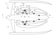
- FIG. 1 is a view in longitudinal section of a turbomachine comprising a heat exchanger, according to a first embodiment of the invention
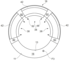
- FIG. 1 is a front view of the tertiary flow stream comprising the heat exchanger, according to the first embodiment
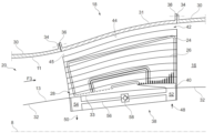
- FIG. 1 is a perspective view in longitudinal section of a heat exchanger of a turbomachine according to a second embodiment
- FIG. 1 shows a partial top view of the heat exchanger according to a third embodiment
- the turbomachine 2 evolves in an air flow F whose movement relative to the turbomachine 2 is generated by the rotation of the propeller 4 and the advancement of the aircraft on which the turbomachine 2 is mounted.
- the air flow F is separated by a first splitter 10 into a radially internal air flow F' and a radially external air flow F2, called secondary flow F2.
- the propeller 4 can be arranged upstream of the first separation nozzle 10 or downstream.
- the radially internal air flow F' passes through a mobile wheel 12 which directs the latter towards a second separation nozzle 14 capable of separating the radially internal air flow F' into a primary flow F1 and a tertiary flow F3, the latter is distinct from the secondary stream F2.
- the first separation beak 10 comprises an internal wall forming a first external guide wall 11 of the radially internal air flow F', said first external guide wall 11 forming a convex profile seen from said radially internal air flow F' .
- the second separation beak 14 comprises an external wall forming a second external guide wall 13 of the radially internal air flow F' having passed through the movable wheel 12, said second external guide wall 13 forming a convex profile seen from the tertiary flow F3.
- the tertiary flow F3 enters a tertiary flow stream 16 radially external to said primary flow F1.
- the tertiary flow F3 passes through a heat exchanger 18 arranged in the tertiary flow vein 16.
- the turbomachine 2 is illustrated symmetrically with respect to the longitudinal axis 8.
- the tertiary flow stream 16 is annular and circumferentially continuous over 360° around the longitudinal axis 8.
- the tertiary flow F3 is a flow that crosses annularly the tertiary flow vein 16.
- the tertiary flow F3 extends essentially along the axial direction and in a position radially between the primary flow F1 and the secondary flow F2.
- the tertiary flow F3 extends in the tertiary flow vein 16 from the radially internal air flow F' downstream of the moving wheel 12 and to the secondary flow F2 after having crossed the heat exchanger 18.
- the turbomachine 2 further comprises a stator (not shown) arranged upstream of the heat exchanger 18 at the level of the tertiary flow stream 16.
- the stator makes it possible to straighten the tertiary flow F3 before the latter crosses the heat exchanger 18 in order to minimize the aerodynamic disturbances of the tertiary flow F3 which can be caused by the moving wheel 12, this makes it possible to optimize the heat exchange between the air and the oil.
- the stator corresponds to a row of stator vanes arranged in the tertiary flow stream downstream of the separation nozzle 14.
- the stator can be arranged upstream of the separation nozzle 14 and downstream of the impeller 12.
- the heat exchanger 18 extends radially and axially in an upstream section 20 of the tertiary flow stream 16, presenting a divergent longitudinal section in the direction of the flow of the tertiary flow F3.
- the heat exchanger 18 can axially overlap a high pressure compressor 15 as well as a low pressure compressor 17, called "booster" 17, said heat exchanger 18 can also be positioned axially above the low pressure compressor 17.
- the heat exchanger 18 is arranged axially between the low pressure compressor 17 and the high pressure compressor 15.
- a "VBV” channel 19 (Variabe Bleed Valve) having an outlet passing through an internal wall of the tertiary flow stream 16 and disposed axially downstream of the heat exchanger 18, the "VBV" channel makes it possible to ensure a function of discharge by returning part of the primary flow F1 to the tertiary flow F3, this makes it possible, for example, to evacuate any ice particles from the primary flow F1 to avoid jamming of the high pressure compressor 15, in particular when the flow rate of the primary flow F1 becomes too weak.
- the arrangement of the outlet of the "VBV" channel 19 downstream of the heat exchanger 18 makes it possible to preserve the latter from a possible risk of jamming.
- the heat exchanger 18 can extend continuously over 360° in the upstream section 20 of the stream 16 around the longitudinal axis 8 of the turbomachine 2.
- the heat exchanger 18 extends so discontinuous over 360° around the longitudinal axis 8 by being subdivided into several angular segments and each can ensure a heat exchange function between the air and the oil which can be different from one segment to another. Examples of the different heat exchange functions will be given later in this description.
- the tertiary flow F3 crosses the heat exchanger 18 occupying the upstream section 20 of the vein 16 at a speed having a Mach number comprised in an interval ranging from 0.1 to 0.6, generally 0.3.
- the divergence of the upstream section 20 of the stream 16 makes it possible to contribute to the slowing down of the air by reducing its speed.
- the tertiary flow stream 16 also includes a downstream section 22 having a convergent longitudinal section following the tertiary flow F3.
- a downstream section 22 having a convergent longitudinal section following the tertiary flow F3.
- the heat exchanger 18 is of the "ACOC” type, an acronym for the English expression “Air-Cooled Oil Cooler”, comprising oil passages which extend into the tertiary flow stream, said oil passages d extend particularly in a radial and axial direction between an upper wall and a lower wall of said heat exchanger 18.
- the heat exchanger 18 of the present invention is different from a "SACOC" surface air-oil exchanger, in which the oil remains in the lower and upper walls and does not cross the exchanger radially.
- the "ACOC" heat exchanger 18 allows a heat exchange between the air and the oil, preferably a cooling of the oil by the air.
- the oil temperature can reach an operating temperature of up to 180°C and a flow rate of up to 30,000 l/h.
- the exchanger 18 can ensure the cooling of the oil used in several components of the aircraft, in particular, an engine, a gearbox, an engine generator and any electronic component requiring cooling.
- a single heat exchanger 18 can combine the cooling of several functions or oil circuits of the turbomachine, and this according to different parameters related to the need for oil cooling, i.e. inlet temperatures, flow rates, outlet temperature requested or the air conditions, the various circuits can be placed in thermal contact or isolated.
- the exchanger 18 and in particular its oil passages can withstand low oil temperature down to -54°C.
- the heat exchanger 18 is of the air/oil type with heat exchange surfaces with the air 26 which are in contact with the oil passages 24.
- the exchange surfaces 26 have a divergent longitudinal section along the tertiary flow F3, i.e. the radial height separating two exchange surfaces 26 downstream of the exchanger is greater than the radial height separating said two exchange surfaces at the upstream of the interchange.
- the exchange surfaces 26 have a cross section which increases along the tertiary flow F3.
- the heat exchanger 18 is a one-piece part obtained by additive manufacturing, and more preferably obtained by laser fusion on a bed of aluminum powder.
- the exchange surfaces 26 are preferably formed by thin plates, and advantageously, each plate delimits two exchange surfaces 26.
- the oil passages 24 are arranged side by side with a number between 1 and 50, and preferably between 5 and 30, and more preferably between 10 and 25. Alternatively, the oil passages 24 can be merged so as to form a single channel.
- the divergence of the heat exchanger 18 is sized to reduce the speed of the air by around 25%, i.e. the tertiary flow F3 passes for example from a speed of Mach 0.33 to a number of Mach about 0.2 at the exit of interchange 18.
- 60% of the cumulative length of said oil passages 24 extend in longitudinal planes distributed angularly around the longitudinal axis 8, and preferably 80% of the cumulative length, in said longitudinal planes.
- the oil passages 24 extending in the longitudinal planes are parallel to the direction of air flow.
- the upstream section 20 of the tertiary flow stream 16 comprises an external casing 30 and an internal casing 32.
- the upstream section 20 further comprises an external intermediate casing 31 and an internal intermediate casing 33, each of said external 31 and internal 33 intermediate casings is integral with the interchange 18.
- oil passages 24 and/or the exchange surfaces 26 are integrally formed with the external intermediate casing 31 as well as with the internal intermediate casing 33 of the exchanger 18.
- the outer casing 30 is an integral part of the outer intermediate casing 31, and at the same time, the inner casing 32 is an integral part of the inner intermediate casing 33.
- the outer casing 30 comprises at an upstream end and/or at a downstream end, a fixing flange 34.
- the outer casing 30 comprises two fixing flanges 34 arranged both at the upstream end and at the the downstream end of exchanger 18.
- each fixing flange 34 is configured to be fixed to the flange fixing 36 belonging to the exchanger 18.
- the fixing flanges 34, 36 are circumferentially continuous around the longitudinal axis 8.
- the mounting direction of the exchanger 18 in the turbomachine is preferably from downstream to upstream, i.e. in the opposite direction to the tertiary flow F3.
- the fixing of the exchanger 18 to the outer casing 30 can be ensured by screwing.
- the exchanger 18 is an integral part of the tertiary flow stream 16 and thus ensures the aerodynamic continuity of the tertiary flow F3 within the stream 16.
- the fixing of the exchanger 18 with the internal casing 32 can be obtained by means of a rigid connection between a fixing flange belonging to the internal casing 32 with another fixing flange belonging to the exchanger 18, and precisely belonging to a angular sector 38 of the exchanger 18.
- the angular sector 38 is an integral part of the exchanger 18 and comprises an oil inlet passage 40 allowing the distribution of the oil in the oil passages 24.
- the fixing is preferably obtained by screwing between the two flanges (not shown) which can be arranged circumferentially around the longitudinal axis 8.
- the exchanger 18 comprises over its total extent along the tertiary flow F3, a free portion of material 42 forming a bypass 42, commonly called an air bypass 42, and can also be called a "FOD" bypass, an acronym for the English expression "Foreign Object Debris".
- an air bypass an acronym for the English expression "Foreign Object Debris”.
- Debris or "FOD” can include birds, hail, hailstones, or any other object that may clog or damage the heat exchanger.
- the exchanger 18 includes the bypass 42 to allow debris to cross the vein 16 without blocking the passage of the tertiary flow F3 through the exchanger 18 or damaging the latter.
- a protective grid can be placed on the front face of the exchanger 18 to further protect the oil passages 24 and the exchange surfaces 26, and without hindering their ability to heat exchange.
- the air by-pass 42 is adjacent to the outer casing 30 of the upstream section 22 of the tertiary flow stream 16.
- the air by-pass 42 is delimited radially outwards by the outer intermediate casing 31 and more precisely delimited radially outwards by an upper face 44 belonging to the outer intermediate casing 31 of the exchanger 18, said upper face 44 is adjacent to the first outer guide wall 11 belonging to the outer casing 30.
- the air bypass 42 is delimited radially inwards by a face 45 belonging to a wall radially delimiting the heat exchange surfaces 26, said wall having a constant radial height.
- the air by-pass 42 extends radially over a height corresponding to a maximum of 20% of a total radial height of the upstream section 22 of the tertiary flow stream 16.
- the height of the by-pass of air 42 extends radially to a maximum of 15% of a total radial height corresponding to the divergent longitudinal section of the vein 16.
- the air bypass 42 has a constant radial height over the total extent of the exchanger 18 following the tertiary flow F3. Indeed, the height of the air bypass 42 remains constant and does not change in any way according to the flow of the air because it is not desired to modify the speed of the latter, only the passage of the debris is expected from the air bypass 42.
- this makes it possible to limit the difference in pressure drops between the air bypass 42 and the rest of the exchanger 18.
- the radial height of the air bypass 42 may vary in order to compensate for any pressure drops which may be caused by aerodynamic disturbances downstream of the exchanger.
- the air bypass 42 may have a convergent and/or divergent longitudinal section.
- FIG. 1 There is a front view, ie in the direction of air flow, of the tertiary flow stream 16 comprising the exchanger 18, of the turbomachine of the .
- the exchanger 18 is distributed angularly in the tertiary flow vein 16, indeed, it can be considered that a plurality of exchangers 18 in the vein 16 represents a single exchanger 18.
- the exchanger 18 comprises several angular sectors 38, each angular sector 38 comprises an oil inlet 48 on the second external guide wall 13 of the radially internal air flow, called internal wall 13 at an angular end of said sector 38.
- the angular sector 38 also comprises at an opposite angular end an oil outlet 50 on the internal wall 13, the opposition of one end relative to the other relates to a radial axis (not shown) located in the middle of the angular sector.
- the oil inlet 48 or the oil outlet 50 is integrally formed in the inner wall 13.
- the oil inlet 48 and the oil outlet 50 are integrally formed in the inner wall 13.
- the angular sector 38 comprises an oil distributor 52 extending circumferentially along the internal wall 13 and an oil collector 54 also extending circumferentially along the internal wall 13.
- angular sectors 38 can comprise a single distributor 52 and a single oil collector 54.
- a single distributor can for example be connected to several cooling circuits of the axial turbomachine.
- the oil distributor 52 includes the oil inlet 48 and the oil manifold includes the oil outlet 50.
- the oil passages 24 extending fluidly into the tertiary flow stream between the corresponding oil inlet 48 and the corresponding oil outlet 50.
- An oil outlet passage 55 is arranged between the oil passages 24 and the oil manifold 54, and a shorting passage may connect the oil inlet passage 40 to the oil outlet passage. oil 55.
- the angular sector 38 comprises a short-circuiting passage 56 of said sector 38, also called an oil bypass 56, the latter being integrally formed in the internal wall 13 and extending fluidically between the inlet 48 and the oil outlet 50 along the internal wall 13.
- the exchanger 18 can comprise several oil bypasses 56.
- the oil bypass 56 makes it possible to ensure the cold operation of the exchanger 18, in particular at temperatures around -40° C., in fact, the cold oil has a high viscosity which is not suitable to allow its passage through the exchanger 18, the oil therefore passes through the oil bypass 56 until it reaches a suitable viscosity.
- defrost circuit may be arranged near or in contact with the oil bypass 56, and may also be in contact with the oil passages 24, the defrosting can ensure the heating of the oil included in the exchanger 18.
- the oil bypass 56 comprises a normally closed valve 58 and capable of opening in the presence of a pressure difference between the oil inlet 48 and the oil outlet 50, greater than or equal to a value limit. Valve 58 can also open when the viscosity of the oil is too high compared to a previously identified threshold.
- the oil inlet 48 is located on a terminal downstream portion of the exchanger 18 while the oil outlet 50 is located on an upstream portion of the exchanger 18. However, the reverse can be done or Both the inlet 48 and the outlet 50 can be located at the level of the downstream or upstream portion.
- the oil inlet 48 is at an angular end of the angular sector 38 as well as the oil inlet passage 40, and the oil outlet 50 as well as the oil outlet passage 55 are located in the opposite angular end of the angular sector 38.
- the oil passages 24 extending from the oil inlet 48 to the oil outlet 50 extend circumferentially over the entire circumferential extent of the heat exchanger. heat 18, thus making it possible to maximize the heat exchange zone between the tertiary flow and the oil.
- FIG. 1 There shows a partial perspective view of an exchanger 118 according to a second embodiment of the invention. It should be noted that a perspective view of the interchange 118 is supposed to have an arcuate profile, however the has been greatly simplified to make it easier to understand.
- the first embodiment consists in positioning the air by-pass 42 being adjacent to the outer casing 30. While the second embodiment consists mainly in positioning an air by-pass 142, having the same geometric configuration as the air bypass 42 described above. In this respect, the exchange surfaces 26 as well as the oil passages and all the other elements forming the exchanger 118 are identical to the exchanger 18.
- the air bypass 142 is configured to be adjacent to the inner casing 32, this involves structural adjustments which will be fully detailed later in this description.
- the air bypass 142 is adjacent to the internal casing (not shown) of the upstream section of the tertiary flow stream.
- the air bypass 142 is delimited radially inwards by the internal intermediate casing 33 and more precisely delimited radially inwards by a lower face 46 belonging to the internal intermediate casing of the exchanger 118, said lower face 46 is adjacent to the internal casing and particularly adjacent to the internal wall 13 illustrated in the preceding figures.
- the lower face 46 forms a continuity of the tertiary flow vein with the internal wall 13, it can therefore be considered that the air bypass 142 is delimited radially inwards by the internal wall 13.
- the air bypass 142 is delimited radially outwards by a face 47 belonging to a wall radially delimiting the heat exchange surfaces 26, said wall having a constant radial height.
- the choice of the embodiment of the present invention can be made according to the overall arrangement of the various elements of the axial turbomachine, and more precisely according to the radial position of the top of one of the blades of the moving wheel with respect to the heat exchanger 18, 118 in combination with the geometric shape of the second outer guide wall 13 as indicated in the .
- the exchanger 18, 118 can be manufactured and adapted according to the architecture of the turbomachine in which it will be mounted in order to anticipate the radial part of the stream 16 which comprises the greatest risk of impact with the debris so that the air bypass 42, 142 is arranged there.
- the turbomachine comprises structural arms 60 adjacent to the angular sectors and extending radially in the tertiary flow stream at junctions between said angular sectors of the exchanger 118.
- Each angular sector of the exchanger 118 extends circumferentially between two structural arms 60, so in the case where the exchanger 118 is angularly subdivided in the tertiary flow stream, said subdivision can be ensured by the structural arms 60.
- the structural arms 60 are arranged axially downstream of the stator in the tertiary flow stream, and preferably between the low pressure compressor and the high pressure compressor.
- Each structural arm 60 comprises an upstream portion comprising a leading edge, the exchanger 118 is arranged downstream of the latter.
- this arrangement makes it possible to further minimize the aerodynamic disturbances of the tertiary flow F3 which may be caused by the moving wheel.
- the structural arm 60 has a cross section with a width decreasing over a downstream half of said section forming a convergent downstream portion 62 of the structural arm 60.
- each structural arm 60 includes a trailing edge
- the exchanger 118 is arranged upstream of said trailing edge.
- the exchanger 118 is arranged between the leading edge and said trailing edge.
- this makes it possible to improve the rigidity of the assembly of the exchanger 118 in the turbomachine and to better control the pressure drops and the aerodynamic disturbances.
- the leading edges of the structural arms 60 make it possible to promote heat exchange in convection between the oil and the tertiary flow F3.
- the exchanger 118 extends circumferentially between two structural arms so that said exchanger 118 is in direct contact with at least one of the two structural arms, and preferably in direct contact with each of the two structural arms 60.
- the heat exchange surfaces 26 are adjacent to the downstream portions 62 of the structural arms 60.
- the exchanger 118 is adjacent in the axial and circumferential direction to the downstream portions 62 of the structural arms 60.
- the exchanger 118 is circumferentially in direct contact (stuck) with the downstream portions 62 while overlapping axially at least 80% of a total axial extent of said downstream portions 62.
- adjacent means here that the exchanger 118 is in contact with at least 80% of the downstream portions 62.
- the heat exchange surfaces 26 have a diverging circumferential profile conforming to the downstream portions 62 of the structural arms 60.
- this makes it possible to limit the pressure drops and to increase the efficiency of the heat exchange between the tertiary flow and the oil within the exchanger 118.
- each downstream portion 62 comprises at least one inclined side profile 65, this latter is inclined with respect to an axial direction and extends over at least 5% of the corresponding side profile 64.
- the inclined side profile 65 has an average inclination which depends on its axial extent compared to that of the side profile 64, the inclination can vary between 5° and 60°.
- the inclination of the inclined side profile 65 is of the order of 30° relative to the side profile 64, said inclination preferably extends over 30% of the axial length of the structural arm 60.
- the oil passages 24 can partially or totally follow the inclination of the inclined side profile 65 of the structural arms 60.
- the oil inlet 40 and oil outlet 55 passages are located at the level of the downstream half 62 in axial projections 61 of the cross section of more large width of the structural arms 60.
- the axial projections 61 are called terminal downstream portions 61, the oil inlet 40 and oil outlet 55 passages are arranged in said terminal downstream portions 61. the oil outlet in order to maximize the circulation of the oil within the exchanger 118 inside the tertiary flow vein.
- the exchanger is arranged axially at the level of the greatest width of the structural arms 60, this advantageously makes it possible to facilitate the assembly of said exchanger which is done from downstream to upstream.
- the oil inlet and/or the oil outlet are located at a distance from a downstream edge 63 of the exchanger 118 which is less than 20% of its total axial extent, and more preferably, at a distance less than 5% of its total extent.
- the air by-pass 142 is delimited circumferentially by the sides 43, the latter can conform to the lateral profile 64, in the , the sides 43 do not conform with the inclined side profile 65.
- the oil inlet passage 40 as well as the oil outlet passage 55 extend radially and laterally to the air bypass 142, the latter two being separated from each other by a distance greater than the circumferential width of the air bypass 142, i.e. between two sides 43.
- the oil inlet passage 40 is distant from the oil outlet passage 55 by a distance greater than at most 20% more than the circumferential width of the air bypass 142, and more preferably , by a distance greater than at most 5% more than the circumferential width of the air bypass 142.
- FIG. 18 There shows a partial top view of the exchanger 18 or 118 illustrating a third embodiment of the invention in which the exchanger 18, 118 presents a change in the number per unit area of its exchange surfaces 26 , called density evolution, located in a portion 66 adjacent to the structural arms 60, with respect to the number per unit area of the exchange surfaces 26 located in a central part 68.
- the adjacent portion 66 can be considered as being a boundary layer to the exchanger, and the evolution of the density is in the circumferential direction and it is at least 20% and preferably 50%.
- the exchanger 18, 118 therefore has 50% more exchange surfaces 26 at the level of the adjacent portion 66 compared to the number of exchange surfaces at the level of the central part 68.
- the change in density in the circumferential direction makes it possible to slow down the air and to accompany its flow as far as the downstream portion 62, thus promoting heat exchange between the oil and the air.
- the reduction in pressure drops and the reduction in the generation of drag at the level of the flow of the tertiary flow F3 also present another advantage of the invention.
- the exchange surfaces 26 of the exchanger have a cross section having a pattern preferably in hexagonal form, however, in order to illustrate the evolution in a simplified way, a rectangular pattern has been illustrated in Figures 7 and 8.
- the number of exchange surfaces 26 per unit area increases in the adjacent part 66 as the circumferential increase of the cross-section at the tertiary flow F3.
- the flow of the tertiary flow F3 gradually diverges in the circumferential direction to follow the inclined side profile 65 of the downstream portion 62 of each structural arm 60.
- the increase in the number of exchange surfaces 26 per unit area takes place along one or more sectors 67, 69, and between each sector of the adjacent part 66, the increase per unit area of the number exchange surfaces 26 is at least 20% and preferably 50%.
- the evolution of the density of the exchange surfaces is also possible in the radial direction by following the divergence of the tertiary flow vein in the longitudinal section, this allows to have the same advantages as the evolution of the density in the axial and circumferential directions.
- the arrangement of the heat exchanger according to the invention and in particular the divergent tertiary flow stream makes it possible to supply the exchanger with air that is cold enough and slow enough so that both the cooling efficiency of oil is ensured and that the aerodynamic losses linked to the presence of the heat exchanger are limited, thus favoring the thrust of the aircraft while contributing to the reduction of carbon dioxide emissions.
- each technical characteristic of each illustrated example is applicable to the other examples.
- the evolution of the density of the heat exchange surfaces can be applied to the exchanger in the three directions, with an air bypass radially adjacent to the external or internal casing.
Landscapes
- Engineering & Computer Science (AREA)
- Mechanical Engineering (AREA)
- General Engineering & Computer Science (AREA)
- Chemical & Material Sciences (AREA)
- Combustion & Propulsion (AREA)
- Physics & Mathematics (AREA)
- Thermal Sciences (AREA)
- Heat-Exchange Devices With Radiators And Conduit Assemblies (AREA)
Abstract
Description
Claims (17)
- Turbomachine axiale (2), comprenant :
- un premier bec de séparation (10) apte à séparer un flux d’air (F) entrant en un flux d’air radialement interne (F’) et un flux d’air radialement externe (F2), dit flux secondaire (F2) ;
- un deuxième bec de séparation (14) apte à séparer le flux d’air radialement interne (F’) en un flux primaire (F1) et un flux tertiaire (F3), le flux tertiaire (F3) étant dans une veine de flux tertiaire (16) radialement externe audit flux primaire (F1), délimitée par une paroi interne (13) et une paroi externe (11) ; et
- un échangeur de chaleur (18, 118) du type air/huile, disposé dans la veine de flux tertiaire (16) ;
- Turbomachine axiale (2), selon la revendication 1, caractérisée en ce que chaque secteur angulaire (38) de l’échangeur de chaleur (18, 118) comprend un ou plusieurs passages d’huile (24) s’étendant dans la veine de flux tertiaire (16) et, de manière fluidique, entre l’arrivée d’huile (48) correspondante et la sortie d’huile (50) correspondante.
- Turbomachine axiale (2), selon la revendication 1, caractérisée en ce que chaque secteur angulaire (38) de l’échangeur de chaleur (18) comprend un distributeur d’huile (52) s’étendant de manière circonférentielle le long de la paroi interne (13) et comprenant l’arrivée d’huile (48), et un collecteur d’huile (54) s’étendant de manière circonférentielle le long de la paroi interne (13) et comprenant la sortie d’huile (50).
- Turbomachine axiale (2), selon la revendication 3, caractérisée en ce que chaque secteur angulaire (38) de l’échangeur de chaleur (18, 118) comprend plusieurs passages d’huile (24) s’étendant dans la veine de flux tertiaire (16) et, de manière fluidique, entre le distributeur d’huile (52) et le collecteur d’huile (54).
- Turbomachine axiale (2), selon l’une des revendications 1 à 4, caractérisée en ce que pour chaque secteur angulaire (38) de l’échangeur de chaleur (18, 118), l’arrivée d’huile (48) et/ou la sortie d’huile (50) est intégralement formée dans la paroi interne (13).
- Turbomachine axiale (2), selon l’une des revendications 1 à 5, caractérisée en ce qu’au moins un des secteurs (38) comprend un passage de mise en court-circuit (56) dudit secteur (38), s’étendant de manière fluidique entre l’arrivée d’huile (48) et la sortie d’huile (50) le long de la paroi interne (13).
- Turbomachine axiale (2), selon la revendication 6, caractérisée en ce que le ou chacun des passages de mise en court-circuit (56) comprend un clapet normalement fermé (58) et apte à s’ouvrir en présence d’une différence de pression entre l’entrée d’huile (48) et la sortie d’huile (50), supérieure ou égale à une valeur limite.
- Turbomachine axiale (2), selon l’une des revendications 6 à 7, caractérisée en ce que le ou chacun des passages de mise en court-circuit (56) est intégralement formé dans la paroi interne (13).
- Turbomachine axiale (2), selon l’une des revendications 1 à 8, caractérisée en ce que pour chaque secteur angulaire (38) de l’échangeur de chaleur (118), l’arrivée d’huile (48) et/ou la sortie d’huile (50) sont situées sur une portion aval terminale (61) dudit échangeur de chaleur (18).
- Turbomachine axiale (2), selon la revendication 9, caractérisée en ce que pour chaque secteur angulaire (38) de l’échangeur de chaleur (118), l’arrivée d’huile (48) et/ou la sortie d’huile (50) sont situées à une distance d’un bord aval (63) dudit échangeur de chaleur (18) au niveau de la paroi interne (13), qui est inférieure à 20% d’une étendue totale dudit échangeur de chaleur (118) le long de ladite paroi interne (13).
- Turbomachine axiale (2), selon l’une des revendications 1 à 10, caractérisée en ce que ladite turbomachine (2) comprend des bras structuraux (60) s’étendant radialement dans la veine de flux tertiaire (16) à des jonctions entre les secteurs (38) de l’échangeur de chaleur (18, 118).
- Turbomachine axiale (2), selon la revendication 11, caractérisée en ce que chaque bras structural (60) présente, dans la veine de flux tertiaire (16), une section transversale avec une largeur diminuant sur une moitié aval (62) de ladite section.
- Turbomachine axiale (2), selon la revendication 12, caractérisée en ce que pour chaque secteur angulaire (38) de l’échangeur de chaleur (118), l’arrivée d’huile (48) et la sortie d’huile (50) sont situées au niveau de la moitié aval (62) dans des projections axiales (61) de la section transversale de plus grande largeur des bras structuraux (60) adjacents audit secteur angulaire (38).
- Turbomachine axiale (2), selon l’une des revendications 1 à 13, caractérisée en ce que l’échangeur de chaleur (118) comprend, sur une étendue totale de l’échangeur de chaleur (118) suivant le flux tertiaire (F3), une portion libre de matière (142) formant un by-pass d’air (142), ledit by-pass d’air (142) étant adjacent à la paroi interne (13) et adjacent au collecteur (54) et/ou au distributeur (52).
- Turbomachine axiale (2), selon la revendication 14, caractérisée en ce que le by-pass d’air (142) est délimité radialement vers l’intérieur par la paroi interne (13).
- Turbomachine axiale (2), selon la revendication 13 et selon l’une des revendications 14 et 15, caractérisée en ce que chaque secteur angulaire (38) de l’échangeur de chaleur (118) comprend un passage d’arrivée d’huile (40) s’étendant radialement et latéralement au by-pass d’air (142) depuis l’arrivée d’huile (48) et un passage de sortie d’huile (55) s’étendant radialement et latéralement au by-pass d’air (142) vers la sortie d’huile (50), lesdits passages d’arrivée d’huile (40) et de sortie d’huile (55) étant situés au niveau de la moitié aval (62) dans des projections axiales (61) de la section transversale de plus grande largeur des bras structuraux (60) adjacents audit secteur angulaire (38).
- Turbomachine axiale (2), selon la revendication 16, caractérisée en ce que le passage d’arrivée d’huile (40) est distant du passage de sortie d’huile (55) d’une distance supérieure à au maximum 20% de plus que la largeur circonférentielle du by-pass d’air (142).
Priority Applications (3)
| Application Number | Priority Date | Filing Date | Title |
|---|---|---|---|
| CN202280087051.5A CN118715357A (zh) | 2021-11-30 | 2022-11-30 | 在第三流中包括渐扩的热交换器的三流轴向涡轮机 |
| EP22823068.6A EP4441348A1 (fr) | 2021-11-30 | 2022-11-30 | Turbomachine axiale triple-flux avec échangeur de chaleur divergeant dans le troisième flux |
| US18/714,191 US12480440B2 (en) | 2021-11-30 | 2022-11-30 | Triple-flow axial turbomachine comprising a diverging heat exchanger in the third flow |
Applications Claiming Priority (4)
| Application Number | Priority Date | Filing Date | Title |
|---|---|---|---|
| EP21211417 | 2021-11-30 | ||
| EP21211417.7 | 2021-11-30 | ||
| BE20215979A BE1030018B1 (fr) | 2021-12-14 | 2021-12-14 | Turbomachine axiale triple-flux avec échangeur de chaleur divergeant dans le troisième flux |
| BEBE2021/5979 | 2021-12-14 |
Publications (1)
| Publication Number | Publication Date |
|---|---|
| WO2023099533A1 true WO2023099533A1 (fr) | 2023-06-08 |
Family
ID=84519443
Family Applications (1)
| Application Number | Title | Priority Date | Filing Date |
|---|---|---|---|
| PCT/EP2022/083790 Ceased WO2023099533A1 (fr) | 2021-11-30 | 2022-11-30 | Turbomachine axiale triple-flux avec échangeur de chaleur divergeant dans le troisième flux |
Country Status (3)
| Country | Link |
|---|---|
| US (1) | US12480440B2 (fr) |
| EP (1) | EP4441348A1 (fr) |
| WO (1) | WO2023099533A1 (fr) |
Cited By (5)
| Publication number | Priority date | Publication date | Assignee | Title |
|---|---|---|---|---|
| DE102023124218A1 (de) * | 2023-04-21 | 2024-10-24 | MTU Aero Engines AG | Flugzeugantrieb und Verfahren zum Betreiben eines Flugzeugantriebs |
| FR3149733A1 (fr) * | 2023-06-09 | 2024-12-13 | Safran | Stator de machine électrique à flux tridimensionnel, procédé de fabrication et machine électrique comportant un tel stator, notamment pour turbomachine d’aéronef |
| WO2025114671A1 (fr) | 2023-11-30 | 2025-06-05 | Safran | Turbomachine pour un aeronef et son procede de refroidissement |
| WO2025114672A1 (fr) | 2023-11-30 | 2025-06-05 | Safran | Turbomachine pour un aeronef et son procede de refroidissement |
| DE102024111957A1 (de) * | 2024-04-29 | 2025-10-30 | MTU Aero Engines AG | Flugtriebwerk |
Citations (8)
| Publication number | Priority date | Publication date | Assignee | Title |
|---|---|---|---|---|
| US4151710A (en) * | 1977-03-11 | 1979-05-01 | United Technologies Corporation | Lubrication cooling system for aircraft engine accessory |
| DE102017121121A1 (de) * | 2017-09-12 | 2019-03-14 | Rolls-Royce Deutschland Ltd & Co Kg | Ölkreislauf eines Flugtriebwerks |
| US10502502B2 (en) * | 2017-02-28 | 2019-12-10 | General Electric Company | Additively manufactured heat exchanger |
| EP3674531A1 (fr) | 2018-12-24 | 2020-07-01 | Safran Aero Boosters SA | Échangeur de chaleur air-huile |
| WO2020183104A1 (fr) * | 2019-03-11 | 2020-09-17 | Liebherr-Aerospace Toulouse Sas | Système de conditionnement d'air équipé d'un système de gestion thermique d'huile et d'air pressurisé |
| US10907500B2 (en) * | 2015-02-06 | 2021-02-02 | Raytheon Technologies Corporation | Heat exchanger system with spatially varied additively manufactured heat transfer surfaces |
| US20210108597A1 (en) | 2019-10-15 | 2021-04-15 | General Electric Company | Propulsion system architecture |
| EP3892949A2 (fr) * | 2020-01-03 | 2021-10-13 | Raytheon Technologies Corporation | Échangeurs et plaques de chaleur d'aéronef |
Family Cites Families (24)
| Publication number | Priority date | Publication date | Assignee | Title |
|---|---|---|---|---|
| US5579650A (en) * | 1994-12-05 | 1996-12-03 | Cleland; Robert K. | Heat exchanger |
| US7861512B2 (en) * | 2006-08-29 | 2011-01-04 | Pratt & Whitney Canada Corp. | Turbofan bypass duct air cooled fluid cooler installation |
| CA2720740C (fr) * | 2008-04-10 | 2014-10-28 | Dana Canada Corporation | Structure de derivation calibree pour echangeur de chaleur |
| US8756910B2 (en) * | 2009-12-31 | 2014-06-24 | Rolls-Royce North American Technologies, Inc. | Gas turbine engine and cooling system |
| US8910465B2 (en) * | 2009-12-31 | 2014-12-16 | Rolls-Royce North American Technologies, Inc. | Gas turbine engine and heat exchange system |
| US8544531B2 (en) * | 2010-06-11 | 2013-10-01 | Hs Marston Aerospace Ltd. | Surface cooler with noise reduction |
| US8770269B2 (en) * | 2010-06-11 | 2014-07-08 | Hs Marston Aerospace Ltd. | Three phase fin surface cooler |
| US9658005B2 (en) * | 2010-11-18 | 2017-05-23 | Hamilton Sundstrand Corporation | Heat exchanger system |
| US9108737B2 (en) * | 2012-08-24 | 2015-08-18 | United Technologies Corporation | Nacelle scoop inlet |
| EP2971604B1 (fr) * | 2013-03-15 | 2020-06-10 | Rolls-Royce North American Technologies, Inc. | Échangeur thermique intégré à un moteur à turbine à gaz et commande d'adaptation du flux |
| US9719418B2 (en) * | 2013-04-01 | 2017-08-01 | General Electric Company | Turbomachine inlet bleed heating assembly |
| US9677474B2 (en) * | 2013-11-18 | 2017-06-13 | Unison Industries, Llc | Surface cooler support mechanism |
| EP3094845B1 (fr) * | 2014-01-15 | 2020-04-29 | United Technologies Corporation | Systèmes de refroidissement pour moteurs à turbine à gaz |
| EP2910887B1 (fr) * | 2014-02-21 | 2019-06-26 | Rolls-Royce Corporation | Échangeurs de chaleur à microcanaux pour le refroidissement intérimaire d'une turbine à gaz et la condensation de même que procede correspondant |
| US9810150B2 (en) * | 2014-10-21 | 2017-11-07 | United Technologies Corporation | Heat exchanger assembly |
| RU2706211C2 (ru) * | 2016-01-25 | 2019-11-14 | Ансалдо Энерджиа Свитзерлэнд Аг | Охлаждаемая стенка компонента турбины и способ охлаждения этой стенки |
| US10253785B2 (en) * | 2016-08-31 | 2019-04-09 | Unison Industries, Llc | Engine heat exchanger and method of forming |
| US10364750B2 (en) * | 2017-10-30 | 2019-07-30 | General Electric Company | Thermal management system |
| US11725584B2 (en) * | 2018-01-17 | 2023-08-15 | General Electric Company | Heat engine with heat exchanger |
| US20200200040A1 (en) * | 2018-12-19 | 2020-06-25 | Unison Industries, Llc | Aircraft surface cooler assembly |
| US10927761B2 (en) * | 2019-04-17 | 2021-02-23 | General Electric Company | Refreshing heat management fluid in a turbomachine |
| US11965697B2 (en) * | 2021-03-02 | 2024-04-23 | General Electric Company | Multi-fluid heat exchanger |
| US12123350B2 (en) * | 2021-03-02 | 2024-10-22 | General Electric Company | Three-stream engine having a heat exchanger |
| WO2022262998A1 (fr) * | 2021-06-18 | 2022-12-22 | Safran Aero Boosters Sa | Structure de turbomachine a trois flux |
-
2022
- 2022-11-30 WO PCT/EP2022/083790 patent/WO2023099533A1/fr not_active Ceased
- 2022-11-30 US US18/714,191 patent/US12480440B2/en active Active
- 2022-11-30 EP EP22823068.6A patent/EP4441348A1/fr active Pending
Patent Citations (8)
| Publication number | Priority date | Publication date | Assignee | Title |
|---|---|---|---|---|
| US4151710A (en) * | 1977-03-11 | 1979-05-01 | United Technologies Corporation | Lubrication cooling system for aircraft engine accessory |
| US10907500B2 (en) * | 2015-02-06 | 2021-02-02 | Raytheon Technologies Corporation | Heat exchanger system with spatially varied additively manufactured heat transfer surfaces |
| US10502502B2 (en) * | 2017-02-28 | 2019-12-10 | General Electric Company | Additively manufactured heat exchanger |
| DE102017121121A1 (de) * | 2017-09-12 | 2019-03-14 | Rolls-Royce Deutschland Ltd & Co Kg | Ölkreislauf eines Flugtriebwerks |
| EP3674531A1 (fr) | 2018-12-24 | 2020-07-01 | Safran Aero Boosters SA | Échangeur de chaleur air-huile |
| WO2020183104A1 (fr) * | 2019-03-11 | 2020-09-17 | Liebherr-Aerospace Toulouse Sas | Système de conditionnement d'air équipé d'un système de gestion thermique d'huile et d'air pressurisé |
| US20210108597A1 (en) | 2019-10-15 | 2021-04-15 | General Electric Company | Propulsion system architecture |
| EP3892949A2 (fr) * | 2020-01-03 | 2021-10-13 | Raytheon Technologies Corporation | Échangeurs et plaques de chaleur d'aéronef |
Cited By (7)
| Publication number | Priority date | Publication date | Assignee | Title |
|---|---|---|---|---|
| DE102023124218A1 (de) * | 2023-04-21 | 2024-10-24 | MTU Aero Engines AG | Flugzeugantrieb und Verfahren zum Betreiben eines Flugzeugantriebs |
| FR3149733A1 (fr) * | 2023-06-09 | 2024-12-13 | Safran | Stator de machine électrique à flux tridimensionnel, procédé de fabrication et machine électrique comportant un tel stator, notamment pour turbomachine d’aéronef |
| WO2025114671A1 (fr) | 2023-11-30 | 2025-06-05 | Safran | Turbomachine pour un aeronef et son procede de refroidissement |
| WO2025114672A1 (fr) | 2023-11-30 | 2025-06-05 | Safran | Turbomachine pour un aeronef et son procede de refroidissement |
| FR3156168A1 (fr) | 2023-11-30 | 2025-06-06 | Safran | Turbomachine pour un aeronef et son procede de refroidissement |
| FR3156167A1 (fr) | 2023-11-30 | 2025-06-06 | Safran | Turbomachine pour un aeronef et son procede de refroidissement |
| DE102024111957A1 (de) * | 2024-04-29 | 2025-10-30 | MTU Aero Engines AG | Flugtriebwerk |
Also Published As
| Publication number | Publication date |
|---|---|
| EP4441348A1 (fr) | 2024-10-09 |
| US20250020077A1 (en) | 2025-01-16 |
| US12480440B2 (en) | 2025-11-25 |
Similar Documents
| Publication | Publication Date | Title |
|---|---|---|
| WO2023099533A1 (fr) | Turbomachine axiale triple-flux avec échangeur de chaleur divergeant dans le troisième flux | |
| EP2336525B1 (fr) | Intégration d'un échangeur de chaleur air-liquide sur moteur | |
| FR3051219B1 (fr) | Aube de turbomachine, telle par exemple qu'un turboreacteur ou un turbopropulseur d'avion | |
| FR3049644A1 (fr) | Aube directrice de sortie pour turbomachine d'aeronef, presentant une fonction amelioree de refroidissement de lubrifiant a l'aide d'une matrice de conduction thermique logee dans un passage interieur de l'aube | |
| FR3046811A1 (fr) | Aube directrice de sortie pour turbomachine d'aeronef, presentant une fonction amelioree de refroidissement de lubrifiant | |
| FR3027624A1 (fr) | Circuit de degivrage d'une levre d'entree d'air d'un ensemble propulsif d'aeronef | |
| FR2938502A1 (fr) | Turbomachine comportant une helice non carenee equipee de moyens de guidage d'air | |
| WO2013150248A1 (fr) | Aubage de redressement de sortie | |
| WO2023203118A1 (fr) | Échangeur de chaleur air-huile comprenant des couloirs pariétaux divergents | |
| EP4441350B1 (fr) | Turbomachine axiale triple-flux avec échangeur de chaleur divergeant dans le troisième flux | |
| WO2023099527A1 (fr) | Turbomachine axiale triple-flux avec échangeur de chaleur divergeant dans le troisième flux | |
| FR3091725A1 (fr) | Ensemble pour une turbomachine | |
| BE1030018B1 (fr) | Turbomachine axiale triple-flux avec échangeur de chaleur divergeant dans le troisième flux | |
| BE1030016B1 (fr) | Turbomachine axiale triple-flux avec échangeur de chaleur divergeant dans le troisième flux | |
| BE1030020B1 (fr) | Turbomachine axiale triple-flux avec échangeur de chaleur divergeant dans le troisième flux | |
| EP4055261A1 (fr) | Echangeur de chaleur comportant une paroi inter-aubes pourvue de générateurs de turbulence creux | |
| EP4441351B1 (fr) | Échangeur de chaleur air-huile avec by-pass pour turbomachine | |
| BE1030017B1 (fr) | Échangeur de chaleur air-huile avec by-pass pour turbomachine | |
| EP4441349B1 (fr) | Échangeur de chaleur air-huile | |
| BE1030019B1 (fr) | Échangeur de chaleur air-huile | |
| EP4483039B1 (fr) | Turbomachine pour aéronef | |
| FR3153855A1 (fr) | Ensemble de turbomachine comprenant un troncon d’un canal empechant la formation de givre | |
| FR3162798A1 (fr) | Turbomachine à poutre structurelle comprenant un conduit de décharge | |
| FR3140122A1 (fr) | Ensemble pour turbomachine d’aeronef comprenant un echangeur de chaleur du type sacoc, de conception ameliore | |
| FR3152038A1 (fr) | Distributeur, notamment pour une turbine d’une turbomachine d’aéronef |
Legal Events
| Date | Code | Title | Description |
|---|---|---|---|
| 121 | Ep: the epo has been informed by wipo that ep was designated in this application |
Ref document number: 22823068 Country of ref document: EP Kind code of ref document: A1 |
|
| WWE | Wipo information: entry into national phase |
Ref document number: 18714191 Country of ref document: US |
|
| WWE | Wipo information: entry into national phase |
Ref document number: 202280087051.5 Country of ref document: CN |
|
| NENP | Non-entry into the national phase |
Ref country code: DE |
|
| ENP | Entry into the national phase |
Ref document number: 2022823068 Country of ref document: EP Effective date: 20240701 |
|
| WWG | Wipo information: grant in national office |
Ref document number: 18714191 Country of ref document: US |