WO2023100267A1 - Dispositif de conversion de puissance, système d'entraînement de moteur et procédé de conversion de puissance - Google Patents
Dispositif de conversion de puissance, système d'entraînement de moteur et procédé de conversion de puissance Download PDFInfo
- Publication number
- WO2023100267A1 WO2023100267A1 PCT/JP2021/043964 JP2021043964W WO2023100267A1 WO 2023100267 A1 WO2023100267 A1 WO 2023100267A1 JP 2021043964 W JP2021043964 W JP 2021043964W WO 2023100267 A1 WO2023100267 A1 WO 2023100267A1
- Authority
- WO
- WIPO (PCT)
- Prior art keywords
- voltage
- smoothing capacitor
- equal
- control unit
- motor
- Prior art date
- Legal status (The legal status is an assumption and is not a legal conclusion. Google has not performed a legal analysis and makes no representation as to the accuracy of the status listed.)
- Ceased
Links
Images









Classifications
-
- H—ELECTRICITY
- H02—GENERATION; CONVERSION OR DISTRIBUTION OF ELECTRIC POWER
- H02P—CONTROL OR REGULATION OF ELECTRIC MOTORS, ELECTRIC GENERATORS OR DYNAMO-ELECTRIC CONVERTERS; CONTROLLING TRANSFORMERS, REACTORS OR CHOKE COILS
- H02P27/00—Arrangements or methods for the control of AC motors characterised by the kind of supply voltage
- H02P27/04—Arrangements or methods for the control of AC motors characterised by the kind of supply voltage using variable-frequency supply voltage, e.g. inverter or converter supply voltage
- H02P27/06—Arrangements or methods for the control of AC motors characterised by the kind of supply voltage using variable-frequency supply voltage, e.g. inverter or converter supply voltage using DC to AC converters or inverters
- H02P27/08—Arrangements or methods for the control of AC motors characterised by the kind of supply voltage using variable-frequency supply voltage, e.g. inverter or converter supply voltage using DC to AC converters or inverters with pulse width modulation
- H02P27/085—Arrangements or methods for the control of AC motors characterised by the kind of supply voltage using variable-frequency supply voltage, e.g. inverter or converter supply voltage using DC to AC converters or inverters with pulse width modulation wherein the PWM mode is adapted on the running conditions of the motor, e.g. the switching frequency
-
- H—ELECTRICITY
- H02—GENERATION; CONVERSION OR DISTRIBUTION OF ELECTRIC POWER
- H02P—CONTROL OR REGULATION OF ELECTRIC MOTORS, ELECTRIC GENERATORS OR DYNAMO-ELECTRIC CONVERTERS; CONTROLLING TRANSFORMERS, REACTORS OR CHOKE COILS
- H02P21/00—Arrangements or methods for the control of electric machines by vector control, e.g. by control of field orientation
- H02P21/05—Arrangements or methods for the control of electric machines by vector control, e.g. by control of field orientation specially adapted for damping motor oscillations, e.g. for reducing hunting
-
- H—ELECTRICITY
- H02—GENERATION; CONVERSION OR DISTRIBUTION OF ELECTRIC POWER
- H02P—CONTROL OR REGULATION OF ELECTRIC MOTORS, ELECTRIC GENERATORS OR DYNAMO-ELECTRIC CONVERTERS; CONTROLLING TRANSFORMERS, REACTORS OR CHOKE COILS
- H02P27/00—Arrangements or methods for the control of AC motors characterised by the kind of supply voltage
- H02P27/04—Arrangements or methods for the control of AC motors characterised by the kind of supply voltage using variable-frequency supply voltage, e.g. inverter or converter supply voltage
- H02P27/06—Arrangements or methods for the control of AC motors characterised by the kind of supply voltage using variable-frequency supply voltage, e.g. inverter or converter supply voltage using DC to AC converters or inverters
Definitions
- the present disclosure relates to a power converter, a motor drive system, and a power conversion method that convert input power into desired output power.
- One type of power conversion device that converts input power into desired output power is a power conversion device that has a configuration in which a smoothing capacitor is connected to a converter circuit such as a diode rectifier circuit.
- a converter circuit such as a diode rectifier circuit.
- a high-voltage, small-capacity smoothing capacitor (first capacitor) and a low-voltage, large-capacity smoothing capacitor (second capacitor) are connected in parallel.
- the power conversion device described in Patent Document 1 turns off the switch connected in series with the second capacitor when the potential difference between both ends of the first capacitor is equal to or greater than the reference value, thereby turning off the second capacitor. are protecting.
- the present disclosure has been made in view of the above, and an object thereof is to obtain a power conversion device capable of suppressing a decrease in life of a smoothing capacitor connected to a converter circuit.
- the power conversion device of the present disclosure includes a first converter circuit that converts an AC voltage from an AC power supply to a DC voltage, and a DC voltage converted by the first converter circuit. and an inverter circuit that converts the DC voltage into an AC voltage and supplies the AC voltage to the motor.
- the power conversion device of the present disclosure is connected between the first converter circuit and the inverter circuit, and when the first voltage threshold is set to a value equal to or higher than the second voltage threshold, the second voltage a first smoothing section in which a first smoothing capacitor having a first breakdown voltage equal to the threshold and a second smoothing capacitor having a second breakdown voltage higher than the first voltage threshold are connected in parallel; It comprises a first cutoff device connected in series with one smoothing capacitor, and a first voltage detector that detects the voltage applied to the second smoothing capacitor.
- the first breaking device when the first detection value, which is the detection value of the applied voltage detected by the first voltage detector, is equal to or greater than the second voltage threshold, the first breaking device is opened, and the rotation speed of the motor is controlled such that the ripple current flowing through the second smoothing capacitor is equal to or less than the rated ripple current.
- the power conversion device has the effect of being able to suppress the deterioration of the life of the smoothing capacitor connected to the converter circuit.
- FIG. 1 is a diagram showing the configuration of a motor drive system including the power conversion device according to the first embodiment
- FIG. FIG. 2 is a diagram showing the configuration of a control unit included in the power converter according to the first embodiment
- FIG. 2 is a diagram showing a hardware configuration example of a control unit included in the power converter according to the first embodiment
- 1 is a block diagram showing an example of a software configuration in a control unit included in the power converter according to Embodiment 1
- FIG. For explaining the correspondence data indicating the relationship between the motor rotation speed and the ripple current flowing through the second smoothing capacitor when the first interrupting device included in the power converter according to the first embodiment is opened. figure FIG.
- FIG. 4 is a diagram for explaining the number of motor revolutions set by the power converter according to the first embodiment using the correspondence data; 4 is a flow chart showing the procedure of control processing by the control unit of the power converter according to the first embodiment;
- FIG. 2 shows a configuration of a motor drive system including a power conversion device according to a second embodiment; The figure which shows the structure of the control part with which the power converter device concerning Embodiment 2 is equipped.
- 9 is a flow chart showing the procedure of control processing by the control unit of the power conversion device according to the third embodiment;
- the figure which shows the structure of the control part with which the power converter device concerning Embodiment 4 is equipped
- a block diagram showing an example of a software configuration in a control unit included in a power converter according to a fourth embodiment. 10 is a flowchart showing the procedure of control processing by the control unit of the power conversion device according to the fourth embodiment;
- FIG. 11 is a diagram showing another configuration example of the motor drive system including the power conversion device according to the fourth embodiment;
- a power conversion device, a motor drive system, and a power conversion method according to embodiments of the present disclosure will be described below in detail based on the drawings.
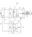
- FIG. 1 is a diagram showing the configuration of a motor drive system including a power conversion device according to a first embodiment.
- a motor drive system 301 is connected to the AC power supply 1 .
- a motor drive system 301 includes a power converter 10 , a motor 6 , and a current detector 32 .
- the motor drive system 301 is a system that converts input power into desired output power by the power converter 10 and supplies the converted power to the motor 6 .
- AC power supply 1 inputs AC power to power converter 10
- motor 6 is driven by the three-phase power generated by power converter 10 .
- the power conversion device 10 is a motor control device that controls the motor 6 by supplying electric power to the motor 6 .
- the power conversion device 10 includes a first converter circuit 2 , a first smoothing section 11 , an inverter circuit 5 and a first cutoff device 21 .
- the first smoothing section 11 has a first smoothing capacitor 3 and a second smoothing capacitor 4 .
- the power conversion device 10 also includes a first voltage detector 31 and a control section 7A. Based on the detection signals from the first voltage detector 31 and the current detector 32, the control unit 7A controls opening/closing of the first breaker 21 and on/off of each switching element of the inverter circuit 5.
- FIG. 1 A first voltage detector 31 and a control section 7A.
- the AC power supply 1 is a commercial AC system, a private generator, or the like.
- the motor 6 includes a three-phase Y-connected stator in which three-phase windings composed of a U-phase winding, a V-phase winding, and a W-phase winding are connected in a Y-shape, and a permanent magnet rotor. permanent magnet motor.
- the AC power supply 1 and the motor 6 are not limited to the configurations described above.
- the stator in the motor 6 may be a three-phase ⁇ -connected stator in which three-phase windings are connected in a ⁇ -shape. .
- the first converter circuit 2 converts the AC voltage from the AC power supply 1 into a DC voltage.
- the first converter circuit 2 is a diode rectifier circuit in which four diode elements are bridge-connected.
- the diode element used in the first converter circuit 2 is not limited to the type of fast recovery diode (FRD: Fast Recovery Diode) or soft recovery diode (SBD: Soft Recovery Diode).
- the diode element used in the first converter circuit 2 may be an element using a material such as SiC (Silicon Carbide), GaN (Gallium Nitride), or Ga2O3 (Gallium oxide).
- the first converter circuit 2 may be a circuit including a booster circuit, a step-down circuit, a step-up/step-down circuit, etc. using switching elements.
- the AC power supply 1 and the first converter circuit 2 are connected via connection lines 61 and 62 .
- the first converter circuit 2 and the inverter circuit 5 are connected via connection lines 63 and 64 .
- connection point 51 arranged on the connection line 63 and the connection point 53 arranged on the connection line 64 are connected via the connection line 65 .
- connection point 52 arranged on the connection line 63 and the connection point 54 arranged on the connection line 64 are connected via the connection line 66 .
- the connection point 52 is a connection point on the rear stage side of the connection point 51
- the connection point 54 is a connection point on the rear stage side of the connection point 53 .
- the first cutoff device 21 and the first smoothing capacitor 3 are connected in series on the connection line 65 . That is, the connection point 51 is connected to the connection point 53 via the first cutoff device 21 and the first smoothing capacitor 3 .
- the second smoothing capacitor 4 is arranged on the connection line 66 . That is, the connection point 52 is connected to the connection point 54 via the second smoothing capacitor 4 .
- the first smoothing capacitor 3 and the second smoothing capacitor 4 are connected in parallel with each other.
- the first voltage threshold is a value equal to or higher than the second voltage threshold (first voltage threshold ⁇ second voltage threshold)
- the first voltage threshold which is the withstand voltage of the first smoothing capacitor (low voltage capacitor) 3
- the breakdown voltage is the same value as the second voltage threshold.
- the second breakdown voltage which is the breakdown voltage of the second smoothing capacitor 4
- the first smoothing capacitor 3 and the second smoothing capacitor 4 smooth the DC voltage converted by the first converter circuit 2 into a stable DC voltage of a constant magnitude.
- first smoothing capacitor 3 and the second smoothing capacitor 4 are such that the ripple current flowing through each smoothing capacitor is Capacitance that is equal to or less than the rated ripple current and that the ripple current flowing through the second smoothing capacitor 4 is equal to or less than the rated ripple current for at least one rotational speed condition when the first breaker 21 is open.
- the first smoothing capacitor 3 and the second smoothing capacitor 4 satisfy all predetermined rotational speed conditions when the first shutoff device 21 is closed, and the first shutoff device 21 is It has a withstand voltage and a capacity that, when open, meet at least one speed condition.
- the amount of ripple (ripple voltage) of the voltage applied to each smoothing capacitor is determined by the chemical properties of the smoothing capacitor (for example, 20 to 40%). It has a withstand voltage and a capacity that are equal to or less than the value obtained by multiplying the withstand voltage of the capacitor (multiplied value).
- the power conversion device 10 can achieve optimum operation with the required capacitor capacity.
- the first smoothing section 11 is not limited to the above configuration, and may have any configuration as long as it can appropriately smooth the voltage.
- the configuration of the first smoothing unit 11 is such that three or more smoothing capacitors including the first smoothing capacitor 3 and the second smoothing capacitor 4 are connected in parallel, and the breakdown voltage is equal to or lower than the second voltage threshold.
- a configuration in which a cutoff device is connected in series to all the smoothing capacitors may be employed. With this configuration, the power conversion device 10 can realize optimum operation with a capacitor capacity as required.
- at least one of the first smoothing capacitor 3 and the second smoothing capacitor 4 may be configured by connecting a plurality of smoothing capacitors in series. Even when the first smoothing section 11 includes three or more smoothing capacitors connected in parallel, each smoothing capacitor has the withstand voltage and capacity described above.
- a mechanical relay is used for the first interrupting device 21, but a switching element made of a semiconductor including a wide bandgap semiconductor may be used.
- the first blocking device 21 includes an IGBT (Insulated Gate Bipolar Transistor), a MOSFET (Metal Oxide Semiconductor Field Effect Transistor), a SiC-MOSFET, a GaN-FET, a GaN-HEMT (High Electron Mobility Transistor). ), Ga2O3-MOSFET A switching element such as may be used.
- the inverter circuit 5 converts the DC voltage, which is converted into a DC voltage by the first converter circuit 2 and smoothed by the first smoothing capacitor 3 and the second smoothing capacitor 4, into an AC voltage and supplies it to the motor 6. .
- the power conversion device 10 can drive the motor 6 at a desired rotation speed (rotational speed) by controlling the AC voltage output from the inverter circuit 5, that is, the AC power.
- the switching elements made of a semiconductor including a wide bandgap semiconductor included in the inverter circuit 5 are not limited to IGBTs and MOSFETs, and may be SiC-MOSFETs, GaN-FETs, GaN-HEMTs, or Ga2O3-MOSFETs.
- the first voltage detector 31 detects the voltage applied to the second smoothing capacitor 4 and outputs the detected value as the detected value Vdc1 to the control section 7A.
- the voltage applied to the second smoothing capacitor 4 and the voltage applied to the first smoothing capacitor 3 are the same. Therefore, the first voltage detector 31 may detect the voltage applied to the first smoothing capacitor 3 .
- a detection value Vdc1 detected by the first voltage detector 31 is a first detection value.
- the current detector 32 is arranged on a connection line connecting the inverter circuit 5 and the motor 6, detects a phase current flowing from the inverter circuit 5 to the motor 6, and outputs the detected value to the control unit 7A as the detected value Iuvw. do.
- the current detector 32 may be a current detector using a current transformer called a CT (Current Transformer) or a current detector using a shunt resistor.
- FIG. 2 is a diagram showing the configuration of a control unit included in the power converter according to the first embodiment.
- Control unit 7A included in power converter 10 of Embodiment 1 receives detection value Vdc1 sent from first voltage detector 31 .
- the control unit 7A also receives the detection value Iuvw sent from the current detector 32 .
- control unit 7A transmits the switching signal X to the first cutoff device 21 based on the detection value Vdc1 of the first voltage detector 31.
- the switching signal X is a signal for switching the open/closed state of the first blocking device 21 .
- control unit 7A transmits drive signals S1 to S6 to each switching element of the inverter circuit 5 based on the detection value Vdc1 of the first voltage detector 31 and the detection value Iuvw of the current detector 32.
- the drive signals S1 to S6 are signals for controlling ON and OFF of each switching element of the inverter circuit 5 .
- the control section 7A can control the opening and closing of the first interrupting device 21 and the ON and OFF of each switching element of the inverter circuit 5 .
- the control unit 7A When the first converter circuit 2 includes a switching element, the control unit 7A outputs the driving signals S1 to S6 for controlling ON and OFF of each switching element of the first converter circuit 2 to the first converter. Send to circuit 2.
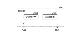
- FIG. 3 is a diagram showing a hardware configuration example of a control unit included in the power converter according to the first embodiment.
- the control section 7A is configured using a processing circuit such as a microcomputer.
- the control section 7A is configured using a processor 100 and a storage device 101 .
- the storage device 101 includes a volatile storage device such as a random access memory and a non-volatile auxiliary storage device such as a flash memory.
- the storage device 101 may include an auxiliary storage device such as a hard disk instead of the flash memory.
- control unit 7A When the control unit 7A is composed of the processor 100 and the storage device 101, each function of the control unit 7A is implemented by software, firmware, or a combination of software and firmware. Software or firmware is written as a program and stored in the storage device 101 .
- the processor 100 executes the program input from the storage device 101 to output the switching signal X and the drive signals S1 to S6.
- the program is input from the auxiliary storage device to the processor 100 via the volatile storage device.
- This program can also be said to be a program for causing the control unit 7A to execute each function realized by the processing circuit.
- This program may be provided by a storage medium storing the program, or may be provided by other means such as a communication medium.
- the processor 100 may output data such as calculation results to the volatile storage device of the storage device 101, or may store the data in an auxiliary storage device via the volatile storage device.
- processor 100 is a CPU (also called a central processing unit, processing unit, arithmetic unit, microprocessor, microcomputer, DSP (Digital Signal Processor)) or system LSI (Large Scale Integration).
- CPU also called a central processing unit, processing unit, arithmetic unit, microprocessor, microcomputer, DSP (Digital Signal Processor)) or system LSI (Large Scale Integration).
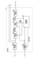
- FIG. 4 is a block diagram showing an example of the software configuration within the control unit provided in the power converter according to Embodiment 1.
- the software in the control unit 7A includes a position/velocity identification unit 200, a dq-axis coordinate conversion unit 201, an open/close signal generation unit 202A, a rotation command generation unit 203, a current control unit 204, and a drive signal generation unit 205.
- a position/velocity identification unit 200 includes a position/velocity identification unit 200, a dq-axis coordinate conversion unit 201, an open/close signal generation unit 202A, a rotation command generation unit 203, a current control unit 204, and a drive signal generation unit 205.
- the position/speed specifying unit 200 uses the voltage command value output from the current control unit 204 and the dq-axis current Idq output from the dq-axis coordinate conversion unit 201 to determine the magnetic poles of the motor 6. Estimate position and rotational velocity. As such an estimation method, an estimation method called an adaptive observer is generally known. The estimation method executed by the position/speed identification unit 200 is not limited to the above estimation method, and any estimation method may be used as long as the magnetic pole position and rotation speed of the motor 6 can be appropriately estimated. . Furthermore, a position detector may be attached to the motor 6 and used as the position/speed identifying section 200 .
- the position/velocity identification unit 200 outputs the estimated magnetic pole position (estimated position) to the dq-axis coordinate conversion unit 201 .
- the position/speed specifying unit 200 outputs the estimated rotation speed (estimated speed) to the rotation command generation unit 203 and the current control unit 204 .
- the dq-axis coordinate conversion unit 201 receives the detected value Iuvw sent from the current detector 32 .
- the dq-axis coordinate conversion unit 201 converts the detection value Iuvw of the current detector 32 into a current value (dq-axis current Idq).
- the dq-axis coordinates are a coordinate system generally used for vector control of a rotating body such as the motor 6 .
- the dq-axis coordinate transformation unit 201 outputs the dq-axis current Idq to the position/speed determination unit 200 and the current control unit 204 .
- the switching signal generator 202A receives the detection value Vdc1 sent from the first voltage detector 31.
- the switching signal generator 202A compares the second voltage threshold ( ⁇ the first voltage threshold) with the detected value Vdc1.
- generation parts produce
- the switching signal generator 202A generates the switching signal X for closing the first blocking device 21 when the detected value Vdc1 is smaller than the second voltage threshold.
- the switching signal generator 202A transmits the generated switching signal X to the first blocking device 21 and the rotation command generator 203 .
- the method of generating the switching signal X by the switching signal generation unit 202A is not limited to the above-described generation method, and any generation method may be used as long as it can generate the switching signal X appropriately.
- the switching signal generation unit 202A closes the first blocking device 21 when the first blocking device 21 is opened for a specific time or more. may be generated.
- the rotation command generator 203 generates a rotation speed command value for the motor 6 based on the switching signal X output from the open/close signal generator 202A. Specifically, when the switching signal X is a signal instructing to close the first shutoff device 21, the rotation command generator 203 freely sets the rotation speed command value according to the operation request of the motor 6. do. On the other hand, when the switching signal X is a signal instructing to open the first blocking device 21, the rotation command generation unit 203 sets the rotation speed command value of the motor 6 based on the correspondence data 80 described later. .
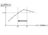
- FIG. 5 shows correspondence data showing the relationship between the motor rotation speed and the ripple current flowing through the second smoothing capacitor when the first breaker provided in the power converter according to the first embodiment is opened. It is a figure for explaining.
- the horizontal axis of the graph shown in FIG. 5 is the number of rotations of the motor 6, and the vertical axis is the ripple current flowing through the second smoothing capacitor 4.
- the correspondence data 80 is data indicating the correspondence between the motor rotation speed and the effective value of the ripple current flowing through the second smoothing capacitor 4 when the first cutoff device 21 is open.
- the correspondence data 80 may be represented graphically as shown in FIG. 5, or may be table data in which the motor rotation speed is associated with the effective value of the ripple current flowing through the second smoothing capacitor 4. may be shown.
- the correspondence data 80 can be obtained, for example, by techniques such as tests and simulations using the power conversion device 10 actually. In this case, by linearly interpolating between the actually acquired data or fitting with an appropriate function, the ripple current flowing through the second smoothing capacitor 4 even for the motor rotation speed for which data is not actually acquired is rms value can be obtained.
- the rotation command generation unit 203 When the rotation command generation unit 203 receives the switching signal X instructing to open the first blocking device 21 from the opening/closing signal generation unit 202A, the rotation command generation unit 203 converts the second smoothing capacitor 4 based on the correspondence data 80 to The motor rotation speed at which the effective value of the flowing ripple current is equal to or less than the rated ripple current Ic_lim is set.
- FIG. 6 is a diagram for explaining the motor rotation speed set by the power converter according to the first embodiment using the correspondence data.
- the rotation command generation unit 203 included in the control unit 7A of the power conversion device 10 reads the correspondence data 80 when receiving the switching signal X instructing to open the first cutoff device 21 .
- the rotation command generation unit 203 sets the motor rotation speed based on the correspondence data 80 .
- the rotation command generator 203 receives the switching signal X instructing the opening of the first blocking device 21 (hereinafter sometimes referred to as the opening instruction timing) at the motor rotation speed N1. 2 acquires the effective value of the ripple current flowing through the smoothing capacitor 4 from the correspondence data 80 .
- the motor rotation speed N1 at the time of the open instruction may be the rotation speed command value at the time of the open instruction, or may be calculated based on the estimated speed sent from the position/speed specifying unit 200 at the time of the open instruction.
- the rotation command generation unit 203 makes the effective value of the ripple current flowing through the second smoothing capacitor 4 equal to or less than the rated ripple current Ic_lim.
- a motor rotation speed (eg, motor rotation speed N2 in FIG. 6) is selected. That is, the rotation command generator 203 selects, from among the motor rotation speeds included in the correspondence data 80, the motor rotation speed at which the effective value of the ripple current is equal to or less than the rated ripple current Ic_lim.
- the rotation command generator 203 may, for example, select a motor rotation speed obtained by subtracting a specific value from the motor rotation speed at the rated ripple current Ic_lim, or may set the motor rotation speed at the rated ripple current Ic_lim to a specific value (from 0 A value of 1 or less) may be selected. It should be noted that the rotation command generation unit 203 may select the motor rotation speed not only by these selection methods but also by other selection methods. The rotation command generator 203 outputs the selected motor rotation speed as a rotation speed command value.
- the rotation command generator 203 continues operation with the current rotation speed command value.
- the correspondence data 80 shown in FIGS. 5 and 6 may be held within the control unit 7A, or may be held in the cloud or the like.
- an external device may determine the rotation speed command value based on the correspondence data 80.
- the power converter 10 receives the rotation speed command value determined by the external device and generates a voltage command value for driving the inverter circuit 5 .
- the power conversion device 10 may determine the rotation speed command value based on the correspondence data 80 .
- the correspondence data 80 shown in FIGS. 5 and 6 are not limited to the above configuration. If the correspondence data 80 is data that appropriately obtains the relationship between the motor rotation speed and the effective value of the ripple current flowing through the second smoothing capacitor 4 when the first cutoff device 21 is open, what kind of data can be used? may be configured to For example, the AC power supply 1 may be provided with a voltage detector, and the correspondence data 80 may be data that considers the dependency of the input voltage from the AC power supply 1 to the power converter 10 . Further, the correspondence data 80 may be data considering the dependence of the output voltage from the power conversion device 10 using Vdc1 obtained from the first voltage detector 31 .
- the current control unit 204 receives the dq-axis current Idq output from the dq-axis coordinate conversion unit 201, the rotation speed command value output from the rotation command generation unit 203, and the estimated speed of the motor 6 output from the position/speed identification unit 200. , a voltage command value for driving the inverter circuit 5 is generated.
- a generation method using a PI (Proportional Integral) controller is generally known.
- the method of generating the voltage command value by the current control unit 204 is not limited to the above-described generation method, and any generation method can be used as long as the dq-axis current Idq is appropriately controlled. good.
- the current control unit 204 may add a method of generating a voltage command value such as pulsating the dq-axis current Idq in order to intentionally pulsate the output of the motor 6 .
- the drive signal generation unit 205 generates drive signals S1 to S6 for PWM (Pulse Width Modulation) control of ON or OFF of each switching element of the inverter circuit 5 based on the voltage command value output from the current control unit 204.
- PWM control is a method generally used as a method for generating drive signals S1 to S6 for switching elements from a voltage command value or a current command value.
- the drive signal generator 205 transmits the generated drive signals S1 to S6 to the inverter circuit 5.
- control unit 7A An example of the process of generating the switching signal X and the rotation speed command value based on the detection value Vdc1 detected by the first voltage detector 31 will be described.
- FIG. 7 is a flow chart showing the procedure of control processing by the control unit of the power converter according to the first embodiment.
- the flowchart of FIG. 7 shows the processing procedure of the processing in which the control unit 7A generates the switching signal X and the rotation speed command value based on the detected value Vdc1.
- the switching signal generation section 202A of the control section 7A receives the detection value Vdc1 from the first voltage detector 31.
- the switching signal generator 202A compares the detection value Vdc1 of the first voltage detector 31 and the second voltage threshold, and determines whether the detection value Vdc1 of the first voltage detector 31 ⁇ the second voltage threshold. (step ST1).
- the switching signal generation unit 202A When the detection value Vdc1 of the first voltage detector 31 ⁇ the second voltage threshold (step ST1, Yes), the switching signal generation unit 202A outputs the switching signal X instructing the opening of the first blocking device 21. Generate and transmit (step ST2). In this case, the switching signal generator 202A transmits the generated switching signal X to the first blocking device 21 and the rotation command generator 203 .
- the rotation command generation unit 203 determines the effective value of the ripple current flowing through the second smoothing capacitor 4 at the motor rotation speed N1 at the time when the switching signal X instructing the opening of the first breaking device 21 is received. Obtained from data 80 . That is, the rotation command generator 203 acquires from the correspondence data 80 the effective value of the ripple current corresponding to the motor rotation speed N1 at the time of the open instruction.
- the rotation command generator 203 compares the effective value of the ripple current flowing through the second smoothing capacitor 4 at the motor rotation speed N1 with the rated ripple current. The rotation command generator 203 determines whether or not the effective value of the ripple current flowing through the second smoothing capacitor 4 > the rated ripple current at the motor rotation speed N1 (step ST3).
- the rotation command generation unit 203 determines the ripple current flowing through the second smoothing capacitor 4.
- a rotation speed command value for the motor 6 that makes the effective value equal to or less than the rated ripple current is selected (step ST4).
- the rotation command generator 203 selects, for example, the motor rotation speed N2 shown in FIG.
- Rotation command generation unit 203 outputs the selected rotation speed command value to current control unit 204 .
- Step ST3 If the effective value of the ripple current flowing through the second smoothing capacitor 4 at the motor rotation speed N1 ⁇ the rated ripple current (step ST3, No), the rotation command generator 203 continues the operation with the rotation speed command value as it is. (Step ST5). That is, the rotation command generation unit 203 outputs the current rotation speed command value to the current control unit 204 .
- step ST6 when the detection value Vdc1 of the first voltage detector 31 ⁇ the second voltage threshold (step ST1, No), the switching signal generation unit 202A instructs to close the first breaking device 21.
- a switching signal X is generated and transmitted (step ST6). That is, the switching signal generation unit 202A instructs to close the first blocking device 21 when the detected value Vdc1 ⁇ the second voltage threshold when the first blocking device 21 is opened.
- a signal X is generated and transmitted. In this case, the switching signal generator 202A transmits the generated switching signal X to the first blocking device 21 and the rotation command generator 203 .
- the rotation command generator 203 freely sets the rotation speed command value of the motor 6 according to the operation request (step ST7).
- Rotation command generation unit 203 outputs the set rotation speed command value to current control unit 204 .
- the current control section 204 controls the rotation speed command value output from the rotation command generation section 203, the dq-axis current Idq output from the dq-axis coordinate conversion section 201, and the position/speed determination section 200.
- a voltage command value is generated using the estimated speed of the motor 6 output from .
- Current control section 204 outputs the generated voltage command value to position/speed identification section 200 and drive signal generation section 205 .
- the drive signal generation unit 205 generates drive signals S1 to S6 for PWM-controlling ON/OFF of each switching element of the inverter circuit 5 based on the voltage command value output from the current control unit 204 .
- the drive signal generator 205 transmits the generated drive signals S1 to S6 to the inverter circuit 5.
- the first voltage detector 31 detects the voltage applied to the second smoothing capacitor 4 having the second breakdown voltage higher than the first voltage threshold. Detected as Vdc1. This detected value Vdc1 corresponds to the voltage applied to the first smoothing capacitor 3 .
- the control unit 7A controls the first cutoff device 21 connected in series with the first smoothing capacitor 3. open. Furthermore, the control unit 7A controls the rotation speed of the motor 6 so that the ripple current flowing through the second smoothing capacitor 4, whose breakdown voltage is higher than the first voltage threshold, is equal to or less than the rated ripple current.
- the power conversion device 10 suppresses the applied voltage of the first smoothing capacitor 3 to the withstand voltage or less, and suppresses the ripple current flowing through the second smoothing capacitor 4 to the rated ripple current or less, thereby achieving high reliability. operation becomes possible.
- the power converter 10 opens the first cutoff device 21 when the detected value Vdc1 detected by the first voltage detector 31 is greater than or equal to the second voltage threshold. ing. Furthermore, the power conversion device 10 controls the rotation speed of the motor 6 so that the ripple current flowing through the second smoothing capacitor 4 is equal to or less than the rated ripple current. Thereby, the power conversion device 10 can suppress the ripple current flowing through the second smoothing capacitor 4 to the rated ripple current or less. Therefore, the power conversion device 10 can suppress the deterioration of the life of the second smoothing capacitor 4 .
- Embodiment 2 will be described with reference to FIGS. 8 to 10.
- FIG. 1 in a motor drive system in which a second converter circuit is connected in parallel with a first converter circuit 2, a power conversion device 10 drives and controls a motor 6.
- FIG. 1 in a motor drive system in which a second converter circuit is connected in parallel with a first converter circuit 2, a power conversion device 10 drives and controls a motor 6.
- FIG. 8 is a diagram showing the configuration of a motor drive system including the power converter according to the second embodiment. 8 that achieve the same functions as those of the motor drive system 301 of Embodiment 1 shown in FIG. 1 are denoted by the same reference numerals, and overlapping descriptions are omitted.
- the reference numerals of the connection points 51 to 54 and the connection lines 63 to 66 are omitted.
- the motor drive system 302 includes a power conversion device 10, a motor 6, a current detector 32, and a drive section 40. That is, the motor drive system 302 includes a drive unit 40 in addition to the components of the motor drive system 301 .
- the drive unit 40 includes a second converter circuit 41 connected in parallel to the first converter circuit 2, a second smoothing unit 43 including a third smoothing capacitor 42, a second voltage detector 44, and a load 45 .
- the drive section 40 is connected to the connection lines 67 and 68 .
- the connecting line 67 is connected to the connecting point 55 on the connecting line 61 and the connecting line 68 is connected to the connecting point 56 on the connecting line 62 .
- the second converter circuit 41 is connected to the connection lines 67 and 68. Also, the second converter circuit 41 and the load 45 are connected via connection lines 69 and 70 .
- connection point 57 arranged on the connection line 69 and the connection point 58 arranged on the connection line 70 are connected via the connection line 71 .
- the third smoothing capacitor 42 is arranged on the connection line 71 . That is, the connection point 57 is connected to the connection point 58 via the third smoothing capacitor 42 .
- the power conversion device 10 includes a control unit 7B instead of the control unit 7A. Based on detection signals from the first voltage detector 31, the second voltage detector 44, and the current detector 32, the control unit 7B opens and closes the first breaker 21 and switches the inverter circuit 5. Controls the on and off of the element.
- the second converter circuit 41 is a diode rectifier circuit in which four diode elements are bridge-connected.
- the diode element used in the second converter circuit 41 is not limited to the types of fast recovery diodes and soft recovery diodes.
- a diode element used in the second converter circuit 41 may be an element using a material such as SiC, GaN, or Ga2O3.
- the second converter circuit 41 may be a circuit including a booster circuit, a step-down circuit, a step-up/step-down circuit, or the like using switching elements.
- the third breakdown voltage which is the breakdown voltage of the third smoothing capacitor 42, is greater than or equal to the second breakdown voltage of the second smoothing capacitor 4.
- the third smoothing capacitor 42 has a capacity such that the ripple current flowing through the third smoothing capacitor 42 is equal to or less than the rated ripple current under all predetermined rotational speed conditions.
- the third smoothing capacitor 42 has a breakdown voltage such that the amount of ripple of the applied voltage is equal to or less than the value obtained by multiplying the breakdown voltage of the smoothing capacitor by a ratio (for example, 20 to 40%) determined by the chemical properties of the smoothing capacitor. and capacity.
- the second smoothing section 43 is not limited to the above configuration, and may have any configuration as long as it can appropriately smooth the voltage.
- the configuration of the second smoothing section 43 (third smoothing capacitor 42) is such that the total breakdown voltage (third breakdown voltage) is equal to or higher than the second breakdown voltage of the second smoothing capacitor 4, and two or more A configuration (smoothing capacitor group) in which smoothing capacitors are connected in series may be employed.
- the second smoothing section 43 may have a configuration in which two or more smoothing capacitors having a withstand voltage equal to or higher than the second withstand voltage of the second smoothing capacitor 4 or the group of smoothing capacitors described above are connected in parallel.
- the load 45 like the inverter circuit 5 and the motor 6, is composed of an inverter circuit and a motor. Note that the load 45 is not limited to the configuration described above, and a load having any configuration may be used.
- the second voltage detector 44 detects the voltage applied to the third smoothing capacitor 42, and outputs the detected value as the detected value Vdc2 to the controller 7B.
- the detected value Vdc2 detected by the second voltage detector 44 is the second detected value.
- FIG. 9 is a diagram showing the configuration of a control unit included in the power converter according to the second embodiment.
- Control unit 7 ⁇ /b>B included in power converter 10 of the second embodiment receives detection value Vdc ⁇ b>1 sent from first voltage detector 31 .
- Control unit 7B also receives detection value Vdc2 sent from second voltage detector 44 .
- the control unit 7B receives the detection value Iuvw sent from the current detector 32 .
- control unit 7B transmits the switching signal X to the first cutoff device 21 based on the detection value Vdc1 of the first voltage detector 31 or the detection value Vdc2 of the second voltage detector 44. Further, the control unit 7B controls each of the inverter circuits 5 based on the detection value Vdc1 of the first voltage detector 31 or the detection value Vdc2 of the second voltage detector 44 and the detection value Iuvw of the current detector 32. Drive signals S1 to S6 are sent to the switching elements. Thereby, the control unit 7B can control the opening/closing of the first breaker 21 and the ON/OFF of each switching element of the inverter circuit 5 .
- the control unit 7B When the first converter circuit 2, the second converter circuit 41, or the load 45 includes switching elements, the control unit 7B outputs drive signals S1 to S6 for controlling on and off of these switching elements. to these switching elements.
- FIG. 10 is a block diagram showing an example of the software configuration within the control unit provided in the power converter according to Embodiment 2.
- FIG. 10 constituent elements that achieve the same functions as those of the control section 7A of Embodiment 1 shown in FIG.
- the software in the control unit 7B includes a position/velocity identification unit 200, a dq-axis coordinate conversion unit 201, an open/close signal generation unit 202B, a rotation command generation unit 203, a current control unit 204, and a drive signal generation unit 205.
- the software in the control unit 7B includes a switching signal generation unit 202B instead of the switching signal generation unit 202A, as compared with the software in the control unit 7A.
- the switching signal generator 202B receives at least one of the detected value Vdc1 sent from the first voltage detector 31 and the detected value Vdc2 sent from the second voltage detector 44.
- the power conversion device 10 When the first voltage detector 31 transmits the detection value Vdc1 to the switching signal generator 202B, the power conversion device 10 does not have to include the second voltage detector 44. Moreover, when the second voltage detector 44 transmits the detection value Vdc2 to the switching signal generation unit 202B, the power conversion device 10 does not have to include the first voltage detector 31 . That is, since the detected value Vdc1 and the detected value Vdc2 are substantially the same value, either one of the detected values Vdc1 and Vdc2 should be input to the switching signal generator 202B.
- the switching signal generation unit 202B converts one of the detection value Vdc1 of the first voltage detector 31 and the detection value Vdc2 of the second voltage detector 44 into a voltage value for generating the switching signal X (hereinafter referred to as (sometimes referred to as switching voltage value).
- the switching signal generator 202B compares the second voltage threshold and the switching voltage value.
- the switching signal generator 202B generates the switching signal X for opening the first blocking device 21 when the switching voltage value is equal to or higher than the second voltage threshold.
- the switching signal generator 202B generates the switching signal X for closing the first blocking device 21 when the switching voltage value is smaller than the second voltage threshold.
- the switching signal generator 202 ⁇ /b>B transmits the generated switching signal X to the first blocking device 21 and the rotation command generator 203 .
- the method of generating the switching signal X by the switching signal generation unit 202B is not limited to the above-described generation method, and any generation method may be used as long as it can generate the switching signal X appropriately.
- the switching signal generation unit 202B generates the first A switching signal X for opening the blocking device 21 may be generated.
- the switching signal generator 202B may adopt the average value of the detection value Vdc1 of the first voltage detector 31 and the detection value Vdc2 of the second voltage detector 44 as the switching voltage value.
- the opening/closing signal generation unit 202B closes the first blocking device 21 when the first blocking device 21 is opened for a specific time or more. may be generated.
- step ST1 differs from the processing procedure described with reference to FIG. 7 of the first embodiment. Specifically, in the first embodiment, the switching signal generation unit 202A determines whether or not the detection value Vdc1 of the first voltage detector 31 ⁇ the second voltage threshold. 2, it is determined whether or not the switching voltage value ⁇ the second voltage threshold.
- the first voltage detector 31 detects the voltage applied to the first smoothing capacitor 3, or the second voltage detector 44 detects the voltage applied to the third smoothing capacitor 42. Detects the applied voltage.
- the control unit 7B switches the first smoothing capacitor 3 is opened. Further, the control unit 7B controls the rotation speed of the motor 6 so that the ripple current flowing through the second smoothing capacitor 4, whose breakdown voltage is higher than the first voltage threshold, is equal to or less than the rated ripple current.
- the power conversion device 10 of the second embodiment can obtain the same effects as the power conversion device 10 of the first embodiment. That is, the power conversion device 10 in the second embodiment can operate with high reliability, and can suppress the life of the second smoothing capacitor 4 from being shortened.
- Embodiment 3 Next, Embodiment 3 will be described with reference to FIGS. 11 to 14.
- FIG. 1 a second breaker is arranged on the connection line 61 between the AC power supply 1 and the first converter circuit 2, and the power conversion device 10 opens and closes the second breaker. Control.
- FIG. 11 is a diagram showing the configuration of a motor drive system including a power conversion device according to the third embodiment.
- constituent elements in FIG. 11 constituent elements that achieve the same functions as those of the motor drive system 301 of Embodiment 1 shown in FIG.
- the reference numerals of the connection points 51 to 54 and the connection lines 63 to 66 are omitted.
- the motor drive system 303 includes the power conversion device 10 , the motor 6 , the current detector 32 and the second cutoff device 22 . That is, the motor drive system 303 includes the second cutoff device 22 in addition to the components of the motor drive system 301 .
- the second cutoff device 22 is arranged on the connection line 61 . That is, the second cutoff device 22 is arranged between the AC power supply 1 and the first converter circuit 2 .
- the second cutoff device 22 may be arranged inside the power conversion device 10 or may be arranged outside the power conversion device 10 .
- the power conversion device 10 includes a control unit 7C instead of the control unit 7A. Based on detection signals from the first voltage detector 31 and the current detector 32, the control unit 7C opens and closes the first breaker 21, opens and closes the second breaker 22, and switches the inverter circuit 5. Controls the on and off of the element.
- a mechanical relay is used for the second cutoff device 22 in the same manner as the first cutoff device 21, but a switching element made of a semiconductor including a wide bandgap semiconductor may be used. That is, the second cutoff device 22 may use switching elements such as IGBTs, MOSFETs, SiC-MOSFETs, GaN-FETs, GaN-HEMTs, or Ga2O3-MOSFETs.
- FIG. 12 is a diagram showing the configuration of a control unit included in the power converter according to the third embodiment.
- Control unit 7C included in power converter 10 of Embodiment 3 receives detection value Vdc1 sent from first voltage detector 31 . Also, the control unit 7C receives the detection value Iuvw sent from the current detector 32 .
- control unit 7C transmits a switching signal X to the first cutoff device 21 based on the detected value Vdc1. Also, the control unit 7C transmits a switching signal Y to the second blocking device 22 based on the detected value Vdc1. The switching signal Y is a signal for switching the open/closed state of the second blocking device 22 .
- Control unit 7C also transmits drive signals S1 to S6 to each switching element of inverter circuit 5 based on detected value Vdc1 and detected value Iuvw. Thereby, the control unit 7C can control opening/closing of the first interrupting device 21, opening/closing of the second interrupting device 22, and ON/OFF of each switching element of the inverter circuit 5.
- FIG. 13 is a block diagram showing an example of the software configuration within the control unit provided in the power conversion device according to Embodiment 3. As shown in FIG. Among the constituent elements in FIG. 13, constituent elements that achieve the same functions as those of the control section 7A of the first embodiment shown in FIG.
- the software in the control unit 7C includes a position/velocity identification unit 200, a dq-axis coordinate conversion unit 201, an open/close signal generation unit 202C, a rotation command generation unit 203, a current control unit 204, and a drive signal generation unit 205.
- the software in the control unit 7C includes a switching signal generation unit 202C instead of the switching signal generation unit 202A, compared with the software in the control unit 7A.
- the switching signal generator 202C receives the detection value Vdc1 sent from the first voltage detector 31.
- the switching signal generator 202 ⁇ /b>C compares the second voltage threshold with the detection value Vdc ⁇ b>1 of the first voltage detector 31 .
- generation parts produce
- the switching signal generator 202C generates the switching signal X for closing the first blocking device 21 when the detected value Vdc1 is smaller than the second voltage threshold.
- the switching signal generation unit 202C sets a third voltage threshold (first voltage threshold ⁇ third voltage threshold ⁇ second withstand voltage) and the detected value Vdc1.
- generation parts produce
- the switching signal generator 202C generates the switching signal Y for closing the second blocking device 22 when the detected value Vdc1 is smaller than the third voltage threshold.
- the switching signal generator 202C transmits the generated switching signal X to the first blocking device 21 and the rotation command generator 203 . Also, the switching signal generator 202 ⁇ /b>C transmits the generated switching signal Y to the second blocking device 22 .
- the opening/closing signal generation unit 202C has a function of closing the blocking devices in order.
- the method of generating the switching signals X and Y by the opening/closing signal generation unit 202C is not limited to the above generation method, and any generation method can be used as long as it can generate the switching signals X and Y appropriately. There may be.
- control unit 7C an example of the process of generating the switching signals X and Y and the rotation speed command value based on the detection value Vdc1 detected by the first voltage detector 31 will be described.
- FIG. 14 is a flow chart showing the procedure of control processing by the control unit of the power converter according to the third embodiment.
- the flow chart of FIG. 14 shows a process in which the control unit 7C generates the switching signals X and Y and the rotational speed command value based on the detected value Vdc1.
- the open/close signal generation unit 202C of the control unit 7C determines the open/closed states of the first shutoff device 21 and the second shutoff device 22 at the end of the previous process. Specifically, the opening/closing signal generation unit 202C determines that both the first shutoff device 21 and the second shutoff device 22 (hereinafter sometimes referred to as the first and second shutoff devices) are open at the end of the previous process. It is determined whether or not it is in the state of being held (step ST11).
- the first and second blocking devices are Gets the duration of the open together state.
- the duration of the state in which both the first and second blocking devices are opened is measured using a timer function or the like.
- the opening/closing signal generation unit 202C determines whether or not the duration of the state in which both the first and second blocking devices are opened is less than a specific time (step ST12a). In other words, the opening/closing signal generator 202C determines whether the continuation of the state in which both the first and second blocking devices are opened has passed the specific time.
- the opening/closing signal generation unit 202C determines that the duration of the state in which both the first and second blocking devices are opened is less than the specific time (step ST12a, Yes), the first and second blocking devices are kept open (step ST13). That is, the opening/closing signal generator 202C generates switching signals X and Y for continuing the state in which both the first and second blocking devices are opened.
- the switching signal generator 202C transmits the generated switching signal X to the first blocking device 21 and the rotation command generator 203 . Also, the switching signal generator 202 ⁇ /b>C transmits the generated switching signal Y to the second blocking device 22 .
- the opening/closing signal generation unit 202C determines that the duration of the state in which both the first and second blocking devices are opened is equal to or longer than the specific time (step ST12a, No), the first blocking device 21 and the second blocking device 202C 2 is closed in order of the breaking device 22 (step ST14). This allows the motor drive system 303 to return to normal operation.
- the opening/closing signal generation unit 202C can prevent excessive inrush current from flowing into the power converter 10 by closing the first and second breaking devices 21 and 22 in this order.
- the switching signal generation unit 202C closes the first breaking device 21 and the second breaking device 22 in this order, and then compares the detection value Vdc1 of the first voltage detector 31 with the third voltage threshold. . Then, the switching signal generator 202C determines whether or not the detection value Vdc1 of the first voltage detector 31 ⁇ the third voltage threshold (step ST15).
- the switching signal generation unit 202C instructs to open the second blocking device 22.
- a signal Y is generated and transmitted to the second cutoff device 22 (step ST16).
- the controller 7C stops the operation of the motor 6 (step ST17).
- step ST11 when the opening/closing signal generation unit 202C determines that either the first or second blocking device was closed at the end of the previous process (step ST11, No), 7 C of control parts perform the process after step ST15.
- step ST15 when the switching signal generation unit 202C determines that the detection value Vdc1 of the first voltage detector 31 ⁇ the third voltage threshold (step ST15, No), the switching signal generation unit 202C , a switching signal Y instructing to close the second blocking device 22 is generated and transmitted to the second blocking device 22 (step ST18).
- control unit 7C executes the processing of steps ST1 to ST7 described with reference to FIG. That is, the control section 7C generates and transmits the switching signal X and the rotation speed command value (steps ST1 to ST7).
- the switching signal generation unit 202C executed both steps ST16 and ST17 when the detection value Vdc1 of the first voltage detector 31 ⁇ the third voltage threshold, but the switching signal generation unit 202C , at least one of steps ST16 and ST17 may be executed.
- control unit 7C controls the detection value Vdc1 of the voltage applied to the second smoothing capacitor 4 whose withstand voltage is higher than the first voltage threshold to be the second voltage threshold higher than the first voltage threshold. 2, the second cutoff device 22 is opened and the operation of the motor 6 is stopped.
- the control unit 7C when the detected value Vdc1 of the voltage applied to the second smoothing capacitor 4 is greater than or equal to the second voltage threshold, connects the first smoothing capacitor 3 in series with Open the connected first shutoff device 21 . Furthermore, the control unit 7C controls the rotation speed of the motor 6 so that the ripple current flowing through the second smoothing capacitor 4 is equal to or less than the rated ripple current. Therefore, similarly to the first embodiment, the power conversion device 10 can operate with high reliability, and can suppress the life of the second smoothing capacitor 4 from being shortened.
- Embodiment 4 Next, Embodiment 4 will be described with reference to FIGS. 15 to 19.
- FIG. In Embodiment 4, the configuration of the motor drive system is a configuration in which the motor drive systems 302 and 303 are combined. That is, in the motor drive system of Embodiment 4, the second converter circuit 41 is connected in parallel to the first converter circuit 2, and the connection line 61 between the AC power supply 1 and the first converter circuit 2 A second shut-off device 22 is arranged in the .
- FIG. 15 is a diagram showing the configuration of a motor drive system including a power conversion device according to the fourth embodiment.
- constituent elements that achieve the same functions as those of the motor drive system 302 of the second embodiment or the motor drive system 303 of the third embodiment are denoted by the same reference numerals, and duplicate descriptions are omitted. do.
- the reference numerals of the connection points 51-54, 57, 58 and the connection lines 63-70 are omitted.
- the motor drive system 304 includes the power converter 10 , the motor 6 , the current detector 32 , the second cutoff device 22 and the drive section 40 . That is, the motor drive system 304 includes the second shutoff device 22 in addition to the components of the motor drive system 302 .
- the second cutoff device 22 is arranged between the connection point 55 and the first converter circuit 2 on the connection line 61 .
- the second cutoff device 22 may be arranged inside the power conversion device 10 or may be arranged outside the power conversion device 10 .
- the power conversion device 10 includes a control unit 7D instead of the control unit 7A. Based on the detection signals from the first voltage detector 31, the second voltage detector 44, and the current detector 32, the control unit 7D opens and closes the first breaker 21 and the second breaker 22. It controls opening/closing and on/off of each switching element of the inverter circuit 5 .
- FIG. 16 is a diagram showing the configuration of a control unit included in the power converter according to the fourth embodiment.
- Control unit 7 ⁇ /b>D included in power converter 10 of the fourth embodiment receives detection value Vdc ⁇ b>1 sent from first voltage detector 31 . Further, control unit 7D receives detection value Vdc2 sent from second voltage detector 44 . Also, the control unit 7D receives the detection value Iuvw sent from the current detector 32 .
- control unit 7D transmits the switching signal X to the first cutoff device 21 based on the detection value Vdc1 of the first voltage detector 31. Further, the control unit 7D transmits a switching signal Y to the second cutoff device 22 based on the detection value Vdc2 of the second voltage detector 44. FIG. Further, the control unit 7D transmits drive signals S1 to S6 to each switching element of the inverter circuit 5 based on the detection value Vdc1 of the first voltage detector 31 and the detection value Iuvw of the current detector 32. do. Thereby, the control unit 7D can control opening/closing of the first interrupting device 21, opening/closing of the second interrupting device 22, and ON/OFF of each switching element of the inverter circuit 5.
- the control unit 7D When the first converter circuit 2, the second converter circuit 41, or the load 45 includes switching elements, the control unit 7D outputs drive signals S1 to S6 for controlling on and off of these switching elements. to these switching elements.
- FIG. 17 is a block diagram showing an example of the software configuration within the control unit provided in the power converter according to Embodiment 4.
- FIG. 17 constituent elements that achieve the same functions as those of the control section 7A of the second embodiment shown in FIG.
- the software in the control unit 7D includes a position/velocity identification unit 200, a dq-axis coordinate conversion unit 201, an open/close signal generation unit 202D, a rotation command generation unit 203, a current control unit 204, and a drive signal generation unit 205.
- the software in the control section 7D includes a switching signal generation section 202D instead of the switching signal generation section 202A, as compared with the software in the control section 7A.
- the switching signal generator 202D receives the detection value Vdc1 sent from the first voltage detector 31 and the detection value Vdc2 sent from the second voltage detector 44.
- the switching signal generator 202D compares the second voltage threshold value with the detection value Vdc2 of the second voltage detector 44 . When the detected value Vdc2 is greater than or equal to the second voltage threshold, the switching signal generator 202D closes the first and second breaking devices 21 and 22 in that order.
- the switching signal generator 202D also compares the detected value Vdc1 with a third voltage threshold that is greater than the first voltage threshold and equal to the second withstand voltage of the second smoothing capacitor 4 .
- the switching signal generator 202D generates a switching signal Y for opening the second blocking device 22 when the detected value Vdc1 is greater than or equal to the third voltage threshold.
- the switching signal generator 202D generates the switching signal Y for closing the second blocking device 22 when the detected value Vdc1 is smaller than the third voltage threshold.
- the switching signal generator 202D compares the second voltage threshold with the detection value Vdc2 of the second voltage detector 44 . Similarly to the switching signal generating section 202A, the switching signal generating section 202D generates the switching signal X for opening the first blocking device 21 when the detected value Vdc2 is equal to or higher than the second voltage threshold. On the other hand, the switching signal generator 202D generates the switching signal X for closing the first blocking device 21 when the detected value Vdc2 is smaller than the second voltage threshold.
- the opening/closing signal generation unit 202D transmits the generated switching signal X to the first blocking device 21 and the rotation command generation unit 203. Also, the switching signal generator 202 ⁇ /b>D transmits the generated switching signal Y to the second blocking device 22 .
- the switching signal generating section 202D has both the function of the switching signal generating section 202B and the function of the switching signal generating section 202C.
- the method of generating the switching signals X and Y by the opening/closing signal generation unit 202D is not limited to the above-described generation method, and any generation method can be used as long as it can generate the switching signals X and Y appropriately. There may be.
- the switching signals X, Y and the rotation speed are determined based on the detection value Vdc1 detected by the first voltage detector 31 and the detection value Vdc2 detected by the second voltage detector An example of processing for generating command values will be described.
- FIG. 18 is a flowchart showing the procedure of control processing by the control unit of the power converter according to the fourth embodiment.
- the flowchart of FIG. 18 shows the processing in which the control unit 7D generates the switching signals X and Y and the rotation speed command value based on the detected value Vdc1 and the detected value Vdc2.
- the control unit 7C executes the process of step ST12a, while the control unit 7D executes the process of step ST12b.
- the processing of steps ST11, ST13 to ST18, ST1 to ST7 executed by the control unit 7C and the processing of steps ST11, ST13 to 18, ST1 to ST7 executed by the control unit 7D are the same processing and are performed in the same processing procedure. executed.
- control unit 7D determines that both the first and second blocking devices were open at the end of the previous process (step ST11, Yes)
- both the first and second blocking devices are opened.
- the switching signal generation unit 202D compares the detection value Vdc2 of the second voltage detector 44 and the second voltage threshold, and determines that the detection value Vdc2 of the second voltage detector 44 ⁇ the second voltage threshold. It is determined whether or not there is (step ST12b).
- step ST12b When the detection value Vdc2 of the second voltage detector 44 ⁇ the second voltage threshold (step ST12b, Yes), the switching signal generator 202D executes the process of step ST13. On the other hand, when the detection value Vdc2 of the second voltage detector 44 ⁇ the second voltage threshold (step ST12b, No), the switching signal generation section 202D executes the processes after step ST14. This eliminates the need for the controller 7D to stop the operation of the motor 6 for a specific time.
- FIG. 19 is a diagram showing another configuration example of the motor drive system provided with the power converter according to the fourth embodiment.
- the constituent elements in FIG. 19 the constituent elements that achieve the same functions as those of the motor drive system 304 shown in FIG.
- the reference numerals of the connection points 51 to 54, 57 and 58 and the connection lines 63 to 70 are omitted.
- the motor drive system 305 includes the power conversion device 10, the motor 6, the current detector 32, the second cutoff device 22, and the drive section 40, similar to the motor drive system 304.
- the second cutoff device 22 is arranged between the connection point 55 and the AC power supply 1 on the connection line 61 .
- the power converter 10 performs the same operation in the motor drive system 305 as in the motor drive system 304 .
- the preferred operation of motor drive system 305 can be realized by combining the operations shown in the first to fourth embodiments.
- the switching voltage value may be used. That is, the switching signal generator 202D may compare the second voltage threshold and the detection value Vdc1 instead of comparing the second voltage threshold and the detection value Vdc2.
- control unit 7D controls the detection value Vdc1 of the voltage applied to the second smoothing capacitor 4 whose withstand voltage is higher than the first voltage threshold to be the second voltage threshold higher than the first voltage threshold. 2, the second cutoff device 22 is opened and the operation of the motor 6 is stopped.
- the control unit 7D sets the withstand voltage to the second voltage threshold.
- the first interrupting device 21 connected in series with the first smoothing capacitor 3 is opened.
- the control unit 7D controls the rotation speed of the motor 6 so that the ripple current flowing through the second smoothing capacitor 4, whose breakdown voltage is higher than the first voltage threshold, is equal to or less than the rated ripple current. Therefore, similarly to the first embodiment, the power conversion device 10 can operate with high reliability, and can suppress the life of the second smoothing capacitor 4 from being shortened.
Landscapes
- Engineering & Computer Science (AREA)
- Power Engineering (AREA)
- Inverter Devices (AREA)
- Control Of Ac Motors In General (AREA)
Abstract
Priority Applications (4)
| Application Number | Priority Date | Filing Date | Title |
|---|---|---|---|
| CN202180102659.6A CN118251831A (zh) | 2021-11-30 | 2021-11-30 | 电力转换装置、马达驱动系统以及电力转换方法 |
| JP2023564320A JP7527502B2 (ja) | 2021-11-30 | 2021-11-30 | 電力変換装置、モータ駆動システム、および電力変換方法 |
| US18/688,148 US12537471B2 (en) | 2021-11-30 | 2021-11-30 | Power converter, motor drive system, and power conversion method |
| PCT/JP2021/043964 WO2023100267A1 (fr) | 2021-11-30 | 2021-11-30 | Dispositif de conversion de puissance, système d'entraînement de moteur et procédé de conversion de puissance |
Applications Claiming Priority (1)
| Application Number | Priority Date | Filing Date | Title |
|---|---|---|---|
| PCT/JP2021/043964 WO2023100267A1 (fr) | 2021-11-30 | 2021-11-30 | Dispositif de conversion de puissance, système d'entraînement de moteur et procédé de conversion de puissance |
Publications (1)
| Publication Number | Publication Date |
|---|---|
| WO2023100267A1 true WO2023100267A1 (fr) | 2023-06-08 |
Family
ID=86611696
Family Applications (1)
| Application Number | Title | Priority Date | Filing Date |
|---|---|---|---|
| PCT/JP2021/043964 Ceased WO2023100267A1 (fr) | 2021-11-30 | 2021-11-30 | Dispositif de conversion de puissance, système d'entraînement de moteur et procédé de conversion de puissance |
Country Status (4)
| Country | Link |
|---|---|
| US (1) | US12537471B2 (fr) |
| JP (1) | JP7527502B2 (fr) |
| CN (1) | CN118251831A (fr) |
| WO (1) | WO2023100267A1 (fr) |
Citations (3)
| Publication number | Priority date | Publication date | Assignee | Title |
|---|---|---|---|---|
| JP2015220840A (ja) * | 2014-05-16 | 2015-12-07 | 三菱電機株式会社 | 電力変換装置およびその制御方法 |
| JP2019096737A (ja) * | 2017-11-22 | 2019-06-20 | 日本ケミコン株式会社 | 電解コンデンサモジュール、フィルタ回路および電力変換器 |
| JP6806280B1 (ja) * | 2020-05-29 | 2021-01-06 | 富士電機株式会社 | ノイズフィルタ及び電力変換装置 |
Family Cites Families (4)
| Publication number | Priority date | Publication date | Assignee | Title |
|---|---|---|---|---|
| JP2012060855A (ja) | 2010-09-13 | 2012-03-22 | Yokogawa Electric Corp | スイッチング電源装置の1次側回路 |
| JP6075067B2 (ja) | 2012-12-28 | 2017-02-08 | ダイキン工業株式会社 | 電力変換装置 |
| JP6303354B2 (ja) * | 2013-09-19 | 2018-04-04 | 株式会社デンソー | モータ駆動装置 |
| US11323025B2 (en) | 2018-05-28 | 2022-05-03 | Mitsubishi Electric Corporation | Power converter |
-
2021
- 2021-11-30 WO PCT/JP2021/043964 patent/WO2023100267A1/fr not_active Ceased
- 2021-11-30 JP JP2023564320A patent/JP7527502B2/ja active Active
- 2021-11-30 CN CN202180102659.6A patent/CN118251831A/zh active Pending
- 2021-11-30 US US18/688,148 patent/US12537471B2/en active Active
Patent Citations (3)
| Publication number | Priority date | Publication date | Assignee | Title |
|---|---|---|---|---|
| JP2015220840A (ja) * | 2014-05-16 | 2015-12-07 | 三菱電機株式会社 | 電力変換装置およびその制御方法 |
| JP2019096737A (ja) * | 2017-11-22 | 2019-06-20 | 日本ケミコン株式会社 | 電解コンデンサモジュール、フィルタ回路および電力変換器 |
| JP6806280B1 (ja) * | 2020-05-29 | 2021-01-06 | 富士電機株式会社 | ノイズフィルタ及び電力変換装置 |
Also Published As
| Publication number | Publication date |
|---|---|
| JP7527502B2 (ja) | 2024-08-02 |
| US12537471B2 (en) | 2026-01-27 |
| JPWO2023100267A1 (fr) | 2023-06-08 |
| CN118251831A (zh) | 2024-06-25 |
| US20240380352A1 (en) | 2024-11-14 |
Similar Documents
| Publication | Publication Date | Title |
|---|---|---|
| CN204046458U (zh) | 电力转换装置及其电动机驱动装置、鼓风机、压缩机、空调机、冰箱、制冷机 | |
| CN107735936A (zh) | 逆变器控制装置以及空气调和机 | |
| JP6075067B2 (ja) | 電力変換装置 | |
| CN105765851B (zh) | 电力转换装置、电动机驱动装置、鼓风机、压缩机、空调机、和冰箱 | |
| CN105556816B (zh) | 电力转换装置和电力转换装置的控制方法 | |
| WO2020021681A1 (fr) | Dispositif de pilotage de moteur électrique et dispositif d'application de cycle de réfrigération | |
| CN107836078A (zh) | 同步电动机控制装置、压缩机驱动装置以及空气调节机 | |
| JPWO2019087243A1 (ja) | 電動機駆動装置、冷凍サイクル装置、空気調和機、給湯機、及び冷蔵庫 | |
| CN111727557B (zh) | 电动机驱动装置以及制冷环路应用设备 | |
| JP6768175B2 (ja) | 空気調和機 | |
| JPWO2020129170A1 (ja) | モータ駆動装置、冷凍サイクル装置、空気調和機、給湯機及び冷蔵庫 | |
| JP7527502B2 (ja) | 電力変換装置、モータ駆動システム、および電力変換方法 | |
| US11264924B2 (en) | Motor driving apparatus and refrigeration cycle equipment | |
| US12244255B2 (en) | Electric motor drive device and refrigeration cycle application device | |
| JP6925527B2 (ja) | モータ駆動装置、モータ駆動装置の制御装置、モータ駆動装置の制御方法、及び空気調和機 | |
| JP7335258B2 (ja) | モータ駆動装置及び空気調和機 | |
| US20220103096A1 (en) | Load driving apparatus, air conditioner, and method for operating load driving apparatus | |
| JP7030921B2 (ja) | 負荷駆動装置及び冷凍サイクル適用機器 | |
| JP7361948B2 (ja) | 電動機駆動装置、冷凍サイクル装置、及び空気調和機 | |
| WO2024089759A1 (fr) | Dispositif d'attaque de moteur et appareil de cycle de réfrigération | |
| WO2022176078A1 (fr) | Dispositif d'attaque de moteur électrique, dispositif à cycle de réfrigération, climatiseur, chauffe-eau et réfrigérateur |
Legal Events
| Date | Code | Title | Description |
|---|---|---|---|
| 121 | Ep: the epo has been informed by wipo that ep was designated in this application |
Ref document number: 21966351 Country of ref document: EP Kind code of ref document: A1 |
|
| WWE | Wipo information: entry into national phase |
Ref document number: 2023564320 Country of ref document: JP |
|
| WWE | Wipo information: entry into national phase |
Ref document number: 18688148 Country of ref document: US |
|
| WWE | Wipo information: entry into national phase |
Ref document number: 202180102659.6 Country of ref document: CN |
|
| WWE | Wipo information: entry into national phase |
Ref document number: 202427039959 Country of ref document: IN |
|
| NENP | Non-entry into the national phase |
Ref country code: DE |
|
| 122 | Ep: pct application non-entry in european phase |
Ref document number: 21966351 Country of ref document: EP Kind code of ref document: A1 |
|
| WWG | Wipo information: grant in national office |
Ref document number: 18688148 Country of ref document: US |