WO2023100295A1 - Bâton de type chauffage sans combustion - Google Patents
Bâton de type chauffage sans combustion Download PDFInfo
- Publication number
- WO2023100295A1 WO2023100295A1 PCT/JP2021/044125 JP2021044125W WO2023100295A1 WO 2023100295 A1 WO2023100295 A1 WO 2023100295A1 JP 2021044125 W JP2021044125 W JP 2021044125W WO 2023100295 A1 WO2023100295 A1 WO 2023100295A1
- Authority
- WO
- WIPO (PCT)
- Prior art keywords
- aerosol
- cooling
- paper
- stick
- filter
- Prior art date
- Legal status (The legal status is an assumption and is not a legal conclusion. Google has not performed a legal analysis and makes no representation as to the accuracy of the status listed.)
- Ceased
Links
Images


Classifications
-
- A—HUMAN NECESSITIES
- A24—TOBACCO; CIGARS; CIGARETTES; SIMULATED SMOKING DEVICES; SMOKERS' REQUISITES
- A24D—CIGARS; CIGARETTES; TOBACCO SMOKE FILTERS; MOUTHPIECES OF CIGARS OR CIGARETTES; MANUFACTURE OF TOBACCO SMOKE FILTERS OR MOUTHPIECES
- A24D1/00—Cigars; Cigarettes
- A24D1/20—Cigarettes specially adapted for simulated smoking devices
-
- A—HUMAN NECESSITIES
- A24—TOBACCO; CIGARS; CIGARETTES; SIMULATED SMOKING DEVICES; SMOKERS' REQUISITES
- A24D—CIGARS; CIGARETTES; TOBACCO SMOKE FILTERS; MOUTHPIECES OF CIGARS OR CIGARETTES; MANUFACTURE OF TOBACCO SMOKE FILTERS OR MOUTHPIECES
- A24D3/00—Tobacco smoke filters, e.g. filter tips or filtering inserts; Filters specially adapted for simulated smoking devices; Mouthpieces of cigars or cigarettes
- A24D3/17—Filters specially adapted for simulated smoking devices
-
- A—HUMAN NECESSITIES
- A24—TOBACCO; CIGARS; CIGARETTES; SIMULATED SMOKING DEVICES; SMOKERS' REQUISITES
- A24F—SMOKERS' REQUISITES; MATCH BOXES; SIMULATED SMOKING DEVICES
- A24F40/00—Electrically operated smoking devices; Component parts thereof; Manufacture thereof; Maintenance or testing thereof; Charging means specially adapted therefor
- A24F40/20—Devices using solid inhalable precursors
Definitions
- the present invention relates to non-combustion heating sticks.
- the non-combustion heating smoking article described in US Pat. No. 6,200,400 comprises a tobacco-containing segment and a cooling segment comprising a polymer-coated paper comprising paper and a polymer layer comprising a polymer disposed on the paper.
- a non-combustion heated smoking article described in US Pat. and a shaped member comprises a tobacco-containing segment and a cooling segment comprising a polymer-coated paper comprising paper and a polymer layer comprising a polymer disposed on the paper.
- An object of the present invention is to provide a non-combustion heating stick that can adjust the temperature or taste of the aerosol while maintaining the delivery amount of the product.
- the first feature of the present invention completed for this purpose is a base member including an aerosol source, and a tubular member that cools the vapor generated by heating the base member to generate an aerosol. and a cooling part, wherein the cooling part has an opening for allowing air to flow from the outside to the inside, and the aerosol is provided inside the opening on the side opposite to the base part with respect to the opening.
- the non-combustion heating stick is provided with a substance capable of exchanging heat with the aerosol or a substance capable of imparting fragrance to the aerosol, and is not provided on the side of the base member rather than the opening.
- a second feature may be that the object provided inside the cooling unit contains a fragrance component.
- a third feature may be that the perfume component is menthol.
- a fourth feature may be that the object provided inside the cooling unit is a gathered sheet.
- a fifth feature may be that the object provided inside the cooling section is a coating layer covering at least a partial region of the inner wall surface of the cooling section.
- a sixth feature may be that the coating layer is formed of a sheet attached to an inner wall surface of the cooling section.
- a seventh feature may be that the coating layer is formed of a coating material applied to an inner wall surface of the cooling section.
- An eighth feature may be that the inner diameter of the cooling part is substantially the same as the outer diameter of the aerosol source.
- a ninth feature is that the base member has a wrapping paper wrapped around the aerosol source, the cooling unit is formed into a tubular shape by rolling the paper, and the cooling unit is formed into a tubular shape.
- the inner diameter of the wrapping paper may be substantially the same as the inner diameter of the wrapping paper.
- a tenth feature further includes a filter portion through which the aerosol passes and tip paper connecting the base portion and the filter portion, and the cooling portion is configured to connect the base portion and the filter portion by the tip paper. It may be a space formed between the filter section.
- the first feature it is possible to adjust the temperature or flavor of the aerosol while maintaining the delivery amount of the product.
- the second feature it is possible to impart flavor and taste to the aerosol while promoting cooling of the aerosol, as compared with a configuration that does not contain a flavor component.
- the temperature of the aerosol experienced by the user can be lowered while imparting a flavor to the aerosol, compared to a configuration that does not contain menthol as a fragrance component.
- cooling of the aerosol can be facilitated while maintaining product delivery compared to non-gathered sheet configurations.
- the intended area of the inner wall surface of the cooling section can be coated.
- the intended area of the inner wall surface of the cooling section can be easily coated.
- the tenth feature it is possible to suppress a decrease in aerosol delivery efficiency compared to a configuration in which a member forming a cooling portion is provided inside the tipping paper.
- FIG. 2 is a diagram showing an example of the configuration of the stick according to the first embodiment, where (a) is a vertical cross section and (b) is a diagram showing an example of a cross section taken along line Ib-Ib.
- FIG. 5 is a diagram showing a stick according to a comparative example of the stick 1 according to the first embodiment; (a) is a diagram showing a stick 1A according to a comparative example. (b) is a diagram showing a stick 1B according to a comparative example. (c) is a diagram showing a stick 1C according to a comparative example.
- FIG. 5 is a diagram showing a stick according to a comparative example of the stick 1 according to the first embodiment;
- (a) is a diagram showing a stick 1A according to a comparative example.
- (b) is a diagram showing a stick 1B according to a comparative example.
- (c) is a diagram showing a stick 1C according to a comparative example.
- FIG. 5 is a diagram showing a stick according to a comparative example of the stick 1 according to the first embodiment;
- (a) is a diagram showing a stick 1D according to a comparative example.
- (b) is a diagram showing a stick 1E according to a comparative example.
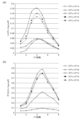
- FIG. 2 is a diagram showing delivery amounts of sticks 1A to 1E, where (a) shows the delivery amount of nicotine and (b) shows the delivery amount of glycerin.
- FIG. 8A is a view showing an example of the structure of a stick according to a second embodiment, where (a) is a longitudinal section and (b) is a view showing an example of a section taken along the VIb-VIb portion; It is a figure which shows the longitudinal cross-section of the stick which concerns on 3rd Embodiment.
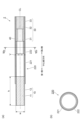
- FIG. 1 is a view showing an example of the configuration of the stick according to the first embodiment, where (a) is a longitudinal section and (b) is a view showing an example of a section taken along line Ib-Ib.
- FIG. 2 is a schematic diagram schematically showing a configuration example of the suction device 100 according to the first embodiment.
- a non-combustion heating stick (hereinafter sometimes referred to as “stick”) 1 according to the first embodiment includes a base portion 10 , a cooling portion 20 and a filter portion 30 .
- the base material portion 10 is formed in a cylindrical shape.
- the direction of the centerline CL of the base member 10 may be referred to as the "centerline direction”.
- the stick 1 further includes a tipping paper 40 that integrates the base material portion 10, the cooling portion 20, and the filter portion 30 by winding them in order in the direction of the center line.
- a tipping paper 40 that integrates the base material portion 10, the cooling portion 20, and the filter portion 30 by winding them in order in the direction of the center line.
- one end side in the centerline direction (left side in FIG. 1) may be referred to as a first side
- the other end side in the centerline direction (right side in FIG. 1) may be referred to as a second side.
- the first side is the end side that is inserted into the suction device 100 .
- the second side is opposite to the first side and is the end side that the user holds in his/her mouth for suction.
- a cross section along the centerline direction is called a "longitudinal cross section", and a cross section taken along a plane perpendicular to the centerline direction is defined as a "transverse cross section".
- the suction device 100 includes a power supply unit 111 that accumulates power and supplies power to each component of the suction device 100, a sensor unit 112 that detects various information about the suction device 100, an information and a notification unit 113 for notifying the user of.
- the suction device 100 also includes a storage unit 114 for storing various information for the operation of the suction device 100, a communication unit 115 for transmitting and receiving information between the suction device 100 and other devices, and the suction device 100. and a control unit 116 for controlling overall internal operations.
- the suction device 100 also includes a heating unit 121 that heats the stick 1, a holding unit 140 that holds the stick 1, an opening 142 that communicates the internal space 141 with the outside, and other components of the suction device 100 from the heating unit 121. and a heat insulator 144 that prevents heat transfer to the element.
- the user performs suction while the stick 1 is held by the holding portion 140 .
- the heating part 121 heats the base material part 10 of the stick 1 .
- the heating part 121 is made of any material such as metal or polyimide.
- the heating part 121 is configured in a film shape and arranged so as to cover the outer periphery of the holding part 140 . Then, when the heating part 121 generates heat, the aerosol source 11 included in the stick 1 is heated from the outer circumference of the stick 1 .
- the heating unit 121 generates heat when supplied with power from the power supply unit 111 .
- power may be supplied when the sensor unit 112 detects that a predetermined user input has been performed. When the temperature of the stick 1 heated by the heating unit 121 reaches a predetermined temperature, the user can suck.
- the power supply may be stopped.
- power may be supplied and aerosol may be generated during a period in which the sensor unit 112 detects that the user has inhaled.
- the heat insulation part 144 is arranged so as to cover at least the outer periphery of the heating part 121 .
- the heat insulating part 144 is made of a vacuum heat insulating material, an airgel heat insulating material, or the like.
- a vacuum insulation material is, for example, a heat insulation material in which heat conduction due to gas is nearly zero by wrapping glass wool and silica (powder of silicon) in a resin film to create a high vacuum state. be.
- the base member 10 has an aerosol source 11 that generates vapor from which an aerosol is generated when heated, and a wrapping paper 12 that covers the outer periphery of the aerosol source 11 .
- the base material part 10 is formed in a cylindrical shape by winding the aerosol source 11 around the wrapping paper 12 .
- the aerosol source 11 may be tobacco-derived, such as, for example, tobacco cuts or tobacco raw materials molded into granules, sheets, or powder.
- the aerosol source 11 may also include non-tobacco sources made from plants other than tobacco, such as mints and herbs.
- the aerosol source 11 may contain perfume.
- the type of fragrance is not particularly limited, and menthol is particularly preferable from the viewpoint of imparting a good flavor.
- flavors may be used individually by 1 type, or may use 2 or more types together.
- the aerosol source 11 may contain a medicament for inhalation by the patient.
- the aerosol source 11 is not limited to solids, and may be polyhydric alcohols such as glycerin and propylene glycol, and liquids such as water. At least part of the base material portion 10 is housed in the internal space 141 of the holding portion 140 while the stick 1 is held by the holding portion 140 .
- the base material portion 10 formed by winding the aerosol source 11 with the wrapping paper 12 preferably has a cylindrical shape that satisfies a shape with an aspect ratio defined by Equation 1 of 1 or more.
- w is the width of the cross section of the base member 10
- h is the size of the base member 10 in the direction of the center line
- h ⁇ w is preferred.
- the shape of the cross section is not limited, and may be a polygon, a polygon with rounded corners, a circle, an ellipse, or the like. is the diameter of the circumscribed circle or the major axis of the circumscribed ellipse. It is preferable that the width of the cross section of the aerosol source 11 constituting the base material portion 10 is 4 mm or more and 9 mm or less.
- the size h of the base material portion 10 in the center line direction can be appropriately changed according to the size of the product. It is more preferable that it is above.
- the size h of the base material portion 10 in the center line direction is usually 70 mm or less, preferably 50 mm or less, more preferably 30 mm or less, and even more preferably 25 mm or less.
- the ratio of the size h of the base material part 10 to the size of the stick 1 is not particularly limited, but from the viewpoint of the balance between the delivery amount and the aerosol temperature, it is usually 10% or more, and 20%. It is preferably 25% or more, more preferably 30% or more.
- the ratio of the size h of the base material portion 10 to the size of the stick 1 is usually 80% or less, preferably 70% or less, more preferably 60% or less, and 50% or less. 45% or less is particularly preferable, and 40% or less is most preferable.
- the content of the aerosol source 11 in the base material portion 10 is not particularly limited, but may be 200 mg or more and 800 mg or less, preferably 250 mg or more and 600 mg or less. This range is particularly suitable for the base member 10 with a circumference of 22 mm and a size of 20 mm in the centerline direction.
- the cut tobacco material contained in the aerosol source 11 is not particularly limited, and known materials such as lamina and backbone can be used.
- dried tobacco leaves are pulverized to an average particle size of 20 ⁇ m or more and 200 ⁇ m or less to obtain pulverized tobacco, which is homogenized and processed into a sheet (hereinafter simply referred to as a homogenized sheet). It can be anything.
- a homogenizing sheet having a size approximately equal to the size in the center line direction of the base material part 10 is chopped substantially horizontally with the center line direction of the base material part 10, and the aerosol source 11 is filled with the so-called strand. can be a type.
- the width of the chopped tobacco is preferably 0.5 mm or more and 2.0 mm or less for filling the aerosol source 11 .
- отно ⁇ еским can be used for the tobacco leaves used for producing the cut tobacco and the homogenized sheet.
- examples include yellow, burley, oriental, landrace, other Nicotiana-tabacum varieties, Nicotiana-Rustica varieties, and mixtures thereof.
- the mixture can be appropriately blended and used so as to obtain the desired taste. Details of tobacco varieties are disclosed in "Tobacco Encyclopedia, Tobacco Research Center, March 31, 2009".
- There are a number of conventional methods for producing homogenized sheets that is, methods for pulverizing tobacco leaves and processing them into homogenized sheets. The first is a method of producing a papermaking sheet using a papermaking process.
- the second method is to mix pulverized tobacco leaves with an appropriate solvent such as water to homogenize the mixture, and then thinly cast the homogenized product on a metal plate or metal plate belt and dry it to produce a cast sheet.
- a third method is to prepare a rolled sheet by mixing a suitable solvent such as water with pulverized tobacco leaves, homogenizing the mixture, and extruding the mixture into a sheet. Details of the types of homogenizing sheets are disclosed in "Encyclopedia of Tobacco, Tobacco Research Center, March 31, 2009".
- the water content of the aerosol source 11 can be 10% by mass or more and 15% by mass or less, preferably 11% by mass or more and 13% by mass or less, relative to the total amount of the aerosol source 11 . Such a water content suppresses the occurrence of winding stains, and improves the winding suitability of the base material portion 10 during manufacturing.
- the aerosol source 11 is not particularly limited, and may contain extracts from various natural products and/or constituents thereof, depending on the application. Extractable substances and/or constituents thereof may include glycerin, propylene glycol, triacetin, 1,3-butanediol, and mixtures thereof.
- the content of the extracting substance and/or its constituent components in the aerosol source 11 is not particularly limited, and from the viewpoint of sufficiently generating an aerosol and imparting a good flavor, it is usually It is 5% by mass or more, preferably 10% by mass or more.
- the content of the extractable substance and/or its constituent components in the aerosol source 11 is usually 50% by mass or less, preferably 15% by mass or more and 25% by mass or less.
- the packing density of the aerosol source 11 is not particularly limited, but is usually 250 mg/cm 3 or more, preferably 300 mg/cm 3 or more, from the viewpoint of securing the performance of the stick 1 and imparting a good flavor. Also, the packing density in the aerosol source 11 is usually 400 mg/cm 3 or less, preferably 350 mg/cm 3 or less.
- the aerosol source 11 may be composed of a tobacco sheet.
- the number of tobacco sheets may be one, or two or more.
- the aerosol source 11 is composed of one tobacco sheet
- a tobacco sheet having one side of a size approximately equal to the size in the center line direction of the object to be filled is used as the object to be filled.
- a filling mode (so-called gathered sheet) is exemplified in a state in which the sheet is folded back multiple times horizontally with respect to the center line direction of the sheet.
- a tobacco sheet having one side of which is approximately the same size as the centerline direction of the object to be filled is wound in a direction orthogonal to the centerline direction of the object to be filled. mentioned.
- the aerosol source 11 is composed of two or more tobacco sheets, for example, a plurality of tobacco sheets each having a size approximately equal to the size in the center line direction of the object to be filled
- a mode in which the material is wound in a direction orthogonal to the center line direction of the material to be filled so as to be arranged concentrically is exemplified.
- Concentrically arranged means that the centers of all the tobacco sheets are arranged at approximately the same position.
- Two or more tobacco sheets may all have the same composition or physical properties, or a part or all of each tobacco sheet may have different compositions or physical properties. Moreover, the thickness of each tobacco sheet may be the same or different. The thickness of each tobacco sheet is not limited, but is preferably 150 ⁇ m or more and 1000 ⁇ m or less, more preferably 200 ⁇ m or more and 600 ⁇ m or less, in terms of balance between heat transfer efficiency and strength.
- the aerosol source 11 prepares a plurality of tobacco sheets having different widths, prepares a laminated body in which the width decreases from the first side to the second side, passes the laminated body through a winding tube, and winds and forms the laminated body. It can be manufactured by According to this manufacturing method, the plurality of tobacco sheets extend in the centerline direction and are arranged concentrically around CL.
- the laminate is preferably prepared so that a non-contact portion is formed between adjacent tobacco sheets after roll-forming. If there is a non-contact portion (gap) between the plurality of tobacco sheets, which is not in contact with the tobacco sheets, the flavor flow path can be secured and the delivery efficiency of the flavor component can be enhanced. On the other hand, since the heat from the heater can be transferred to the outer tobacco sheets through the contact portions of the plurality of tobacco sheets, high heat transfer efficiency can be ensured.
- an embossed tobacco sheet is used, adjacent tobacco sheets are laminated without bonding the entire surfaces of adjacent tobacco sheets, and adjacent tobacco sheets are stacked together.
- the entire or part of the adjacent tobacco sheets are lightly adhered so that they can be separated after roll-forming, thereby preparing a laminate.
- the wrapping paper 12 may be arranged on the end surface of the first side of the laminate.
- the packing density of the aerosol source 11 is not particularly limited, but is usually 250 mg/cm 3 or more, preferably 300 mg/cm 3 or more, from the viewpoint of securing the performance of the stick 1 and imparting a good flavor. Also, the packing density of the aerosol source 11 is usually 400 mg/cm 3 or less, preferably 350 mg/cm 3 or less.
- Polyols such as glycerin, propylene glycol, and 1,3-butanediol may be added to tobacco sheets.
- the amount added to the tobacco sheet is preferably 5% by mass or more and 50% by mass or less, more preferably 15% by mass or more and 25% by mass or less, relative to the dry mass of the tobacco sheet.
- Tobacco sheets can be appropriately manufactured by known methods such as paper making, slurrying, and rolling. Note that the uniformizing sheet described above can also be used.
- papermaking it can be manufactured by a method including the following steps. 1) Dry tobacco leaves are crushed and extracted with water to separate the water extract and residue. 2) Dry and concentrate the water extract under reduced pressure. 3) Pulp is added to the residue, fiberized with a refiner, and then paper is made. 4) A concentrated solution of the water extract is added to the paper sheet and dried to obtain a tobacco sheet. In this case, a step of removing some components such as nitrosamines may be added (see JP-T-2004-510422).
- the slurry method it can be produced by a method including the following steps.
- a non-woven tobacco sheet manufactured by a method including the following steps can also be used. 1) Mix powdered tobacco leaves and a binder. 2) The mixture is sandwiched between non-woven fabrics. 3) Forming the laminate into a certain shape by heat welding to obtain a non-woven tobacco sheet.
- the types of raw material tobacco leaves used in each of the above methods may be the same as those described for the aerosol source 11 containing cut tobacco.
- the composition of the tobacco sheet is not particularly limited, for example, the content of the tobacco raw materials (tobacco leaves) is preferably 50% by mass or more and 95% by mass or less with respect to the total mass of the tobacco sheet.
- the tobacco sheet may also contain a binder, and examples of such binders include guar gum, xanthan gum, carboxymethylcellulose, sodium salts of carboxymethylcellulose, and the like.
- the amount of the binder is preferably 1% by mass or more and 10% by mass or less with respect to the total mass of the tobacco sheet.
- the tobacco sheet may further contain other additives. Examples of additives include fillers such as pulp.
- the structure of the wrapping paper 12 used for the base material portion 10 is not particularly limited, and can be a general form, for example, one containing pulp as a main component.
- pulp in addition to wood pulp such as softwood pulp and hardwood pulp, non-wood pulp such as flax pulp, hemp pulp, sisal pulp, and esparto, which are generally used for wrapping paper 12 for tobacco products, can be used. It may be obtained by mixing and manufacturing.
- the types of pulp that can be used include chemical pulp, ground pulp, chemi-grand pulp, thermomechanical pulp, and the like prepared by kraft cooking, acid/neutral/alkaline sulfite cooking, soda salt cooking, and the like.
- the winding paper 12 is manufactured by preparing and uniforming the texture in the papermaking process using a fourdrinier paper machine, a cylinder paper machine, a circular and short composite paper machine, and the like. If necessary, a wet strength agent may be added to impart water resistance to the wrapping paper 12, or a sizing agent may be added to adjust the printing condition of the wrapping paper 12. Furthermore, aluminum sulfate, various anionic, cationic, nonionic or amphoteric retention improvers, drainage improvers, papermaking internal additives such as paper strength agents, and dyes, pH adjusters, Papermaking additives such as antifoam agents, pitch control agents, and slime control agents can be added.
- the basis weight of the base paper for the wrapping paper 12 is, for example, usually 20 gsm or more, preferably 25 gsm or more. On the other hand, the basis weight is usually 65 gsm or less, preferably 50 gsm or less, more preferably 45 gsm or less.
- the thickness of the wrapping paper 12 is not particularly limited, and is usually 10 ⁇ m or more, preferably 20 ⁇ m or more, more preferably 30 ⁇ m or more, from the viewpoints of rigidity, air permeability, and ease of adjustment during paper production.
- the thickness of the wrapping paper 12 is usually 100 ⁇ m or less, preferably 75 ⁇ m or less, more preferably 50 ⁇ m or less.
- the shape of the wrapping paper 12 for producing the base material part 10 can be square or rectangular.
- the length of one side can be about 12 mm or more and 70 mm or less. , and a more preferable length is about 23 mm.
- the aerosol source 11 is wound with the wrapping paper 12 in a cylindrical shape, for example, in the circumferential direction, the end of the wrapping paper 12 and the end of the wrapping paper 12 on the opposite side are overlapped by about 2 mm and glued to form a cylindrical paper. It has the shape of a tube in which the aerosol source 11 is filled.
- the size of the rectangular wrapping paper 12 can be determined by the size of the base material portion 10 .
- the paper wrapper 12 may also contain fillers.
- the content of the filler can be 10% by mass or more and less than 60% by mass, preferably 15% by mass or more and 45% by mass or less, based on the total mass of the wrapping paper 12 .
- the filler content is preferably 15% by mass or more and 45% by mass or less in a preferable basis weight range (25 gsm or more and 45 gsm or less).
- the filler content is preferably 15 mass % or more and 45 mass % or less, and when the basis weight is 35 gsm or more and 45 gsm or less, the filler content is 25 mass % or more. It is preferably 45% by mass or less.
- a filler calcium carbonate, titanium dioxide, kaolin, and the like can be used, but from the viewpoint of enhancing flavor and whiteness, it is preferable to use calcium carbonate.
- auxiliary agents other than base paper and fillers may be added to the wrapping paper 12.
- a water resistance improver may be added to improve water resistance.
- Water resistance improvers include wet strength agents (WS agents) and sizing agents.
- wet strength agents include urea formaldehyde resin, melamine formaldehyde resin, polyamide epichlorohydrin (PAE), and the like.
- sizing agents include rosin soap, alkyl ketene dimer (AKD), alkenyl succinic anhydride (ASA), and highly saponified polyvinyl alcohol having a degree of saponification of 90% or more.
- a paper strength agent may be added, and examples thereof include polyacrylamide, cationic starch, oxidized starch, CMC, polyamide epichlorohydrin resin, polyvinyl alcohol, and the like.
- polyacrylamide, cationic starch, oxidized starch, CMC, polyamide epichlorohydrin resin, polyvinyl alcohol, and the like examples thereof include polyacrylamide, cationic starch, oxidized starch, CMC, polyamide epichlorohydrin resin, polyvinyl alcohol, and the like.
- a coating agent may be added to at least one of the front and back sides of the wrapping paper 12 .
- the coating agent is not particularly limited, but a coating agent capable of forming a film on the paper surface and reducing liquid permeability is preferred.
- alginic acid and its salts e.g. sodium salts
- polysaccharides such as pectin
- cellulose derivatives such as ethyl cellulose, methyl cellulose, carboxymethyl cellulose, nitrocellulose
- starch and derivatives thereof e.g. carboxymethyl starch, hydroxyalkyl starch and cationic starch
- ether derivatives such as starch acetate, starch phosphate and ester derivatives such as starch octenylsuccinate).
- the cooling unit 20 is arranged adjacent to the base material unit 10 and the filter unit 30, and is provided in the molding paper 21 which is cylindrically molded so that the cross section is hollow (cavity). and a heat exchanger 22 .
- Forming paper 21 has openings V through which air flows from the outside to the inside.
- the heat exchanging material 22 is provided on the side opposite to the base material portion 10 with respect to the opening V. As shown in FIG.
- the size of the cooling part 20 in the centerline direction can be appropriately changed according to the size of the product, but it is usually 5 mm or more, preferably 10 mm or more, and more preferably 15 mm or more. Also, the size of the cooling part 20 in the center line direction is usually 35 mm or less, preferably 30 mm or less, and more preferably 25 mm or less. By setting the size of the cooling unit 20 in the center line direction to the above-described lower limit or more, it is possible to secure a sufficient cooling effect and obtain a good flavor. It is possible to suppress the loss caused by the aerosol adhering to the forming paper 21 .
- the forming paper 21 is cylindrical, and its inner diameter can be appropriately changed according to the size of the product.
- the inner diameter of the forming paper 21 is preferably substantially the same as the inner diameter of the wrapping paper 12 .
- This "substantially identical" means, for example, a difference of about two layers of the wrapping paper 12 or the forming paper 21, a difference within 1 mm from the outer diameter of the aerosol source 11, preferably within 0.5 mm, a difference within 1 mm from the inner diameter of the wrapping paper 12, Preferably, a difference within 0.5 mm is regarded as substantially the same.
- the thickness of the molding paper 21 is not particularly limited, and may be, for example, 5 ⁇ m or more and 500 ⁇ m or less, or 10 ⁇ m or more and 250 ⁇ m or less.
- the material of the forming paper 21 is not particularly limited.
- pulp may be the main component, and polyethylene, polypropylene, polyvinyl chloride, polyethylene terephthalate, polylactic acid, cellulose acetate, and aluminum foil may be used. It may be a caustic-based one, or any combination thereof.
- the forming paper 21 may be formed by a thin sheet of material that is crumpled to form channels and then pleated, gathered and folded to increase the inner surface area. .
- the cooling part 20 is provided with a plurality of openings V (also called “ventilation filter (Vf)" in this technical field) concentrically and circumferentially.
- the aperture V is a hole penetrating the forming paper 21 .
- the shape of the hole can be exemplified by a polygon, a polygon with rounded corners, a circle, an ellipse, or the like.
- the opening V exists in a region where air can flow from the outside of the stick 1 , in other words, in a region where the stick 1 is held by the holding portion 140 of the suction device 100 and protrudes from the opening 142 .
- the cooling unit 20 Due to the presence of the openings V, air flows into the inside of the forming paper 21 of the cooling unit 20 from the outside during suction, and the temperature of steam and air flowing in from the base material unit 10 can be lowered. Furthermore, by setting the position where the cooling unit 20 is provided within a region of 4 mm or more in the direction of the cooling unit 20 from the boundary between the cooling unit 20 and the filter unit 30, not only the cooling capacity is improved, but also the heat generated by heating It is possible to suppress the retention of the substance (product) in the cooling unit 20 and improve the delivery amount of the product. Then, when the base material portion 10 is heated, the vapor generated with the aerosol as the condensation nucleus is liquefied by contacting the air from the outside and the temperature is lowered, thereby promoting the generation of the aerosol. .
- the number of hole groups may be one, or two or more.
- the number of hole groups may be one, or two or more.
- there are two or more hole groups from the viewpoint of improving the delivery amount of the component generated by heating, from the boundary between the cooling unit 20 and the filter unit 30, in the region of less than 4 mm in the direction of the cooling unit 20 side It is preferable not to provide an aperture group.
- the tip paper 40 has the openings V provided in the cooling portion 20. It is preferable that the opening V is provided at the position directly above.
- a chip paper 40 having holes V overlapping the holes V may be prepared and wound. It is preferable to make a hole through the cooling part 20 and the tipping paper 40 at the same time after making the non-stick stick 1 .
- the region where the opening V exists is not particularly limited as long as it is a region of 4 mm or more in the direction of the cooling unit 20 from the boundary between the cooling unit 20 and the filter unit 30 from the viewpoint of improving the product delivery by heating.
- the area is preferably 4.5 mm or more, more preferably 5 mm or more, and even more preferably 5.5 mm or more.
- the region where the opening V exists is preferably a region of 15 mm or less, more preferably 10 mm or less, from the boundary between the cooling unit 20 and the filter unit 30.
- the area is 7 mm or less, more preferably.
- the region where the opening V exists is preferably a region of 16 mm or less from the boundary between the cooling part 20 and the base material part 10, and 15.5 mm or less. , more preferably 15 mm or less, and particularly preferably 14.5 mm or less.
- the apertures V are provided so that the ratio of air inflow through the apertures V is 10% by volume or more and 90% by volume or less when sucked at 17.5 ml/sec by an automatic smoking machine.
- This "air inflow ratio” is the volume ratio of the air that has flowed in from the opening V when the ratio of the air sucked from the mouth end is 100% by volume.
- the air inflow ratio is preferably 50% by volume or more and 80% by volume or less, more preferably 55% by volume or more and 75% by volume or less.
- the number of holes V per hole group is selected from a range of 5 to 50, and the diameter of the holes V is set to a range of 0.1 mm to 0.5 mm. can be selected from and achieved by a combination of these selections.
- the air inflow rate can be measured by a method conforming to ISO9512 using a winding quality measuring instrument (eg, SODIMAX D74/SODIM manufactured by SAS).
- the heat exchange material 22 is a material that can exchange heat with the aerosol passing through the cooling unit 20 or a material that can add fragrance to the aerosol.
- the heat exchanging material 22 is provided inside the cylindrical forming paper 21 of the cooling section 20 on the opposite side of the opening V from the substrate section 10 .
- the heat exchanging material 22 preferably includes a cooling element that undergoes a phase transition at the temperature inside the cooling section 20 to absorb heat. Thereby, the heat exchange material 22 can promote cooling of the aerosol passing through the cooling section 20 .
- the heat exchange material 22 preferably contains a fragrance from the viewpoint of imparting a good smoking taste to the aerosol. Accordingly, when the heat exchange material 22 is applied to the inside of the forming paper 21, for example, the aerosol passing through the cooling section 20 can be imparted with a flavor, or in other words, can be scented.
- the type of cooling element is not particularly limited, but biodegradable polymers and edible polymers are preferred.
- the glass transition temperature of the cooling element is preferably 400° C. or lower, more preferably 200° C. or lower, from the viewpoint of allowing the cooling element to undergo a phase transition and endotherm at the temperature in the cooling unit 20 .
- the temperature is preferably 100° C. or lower, and more preferably 100° C. or lower.
- the lower limit of the glass transition temperature of the cooling element is not particularly limited, it is, for example, 40° C. or higher.
- the glass transition temperature of the cooling element is specifically a value measured with a differential scanning calorimeter (trade name: "DSC7000", manufactured by Hitachi High-Tech Science). Further, from the viewpoint of easily obtaining a cooling effect by adsorbing water vapor in the aerosol, it is preferable that the affinity with water is high.
- cooling elements include polylactic acid, polyvinyl alcohol (PVA), cellulose acetate, trehalose, maltose, sucrose, maltitol, glucose, wax, wax, hydrogenated oil, and the like. These may be used alone or in combination of two or more.
- PVA polyvinyl alcohol
- POVACOAT polyvinyl alcohol/acrylic acid/methyl methacrylate copolymer
- the heat exchange material 22 preferably contains a perfume component, and more preferably contains the perfume component in the cooling element.
- the cooling element of the heat exchange material 22 provided in the molding paper 21 contains a perfume component
- the perfume component is held in the polymer, so volatilization of the perfume component before use can be suppressed.
- part of the heat exchange material 22 becomes rubbery or melts, gradually releasing the perfume component from the cooling element.
- the perfume component can be stably supplied throughout the inhalation.
- the fragrance component is contained in the cooling unit 20
- the amount of heat in the aerosol is absorbed by vaporization, sublimation, etc. of the fragrance component, and a cooling effect can be expected.
- the types of flavor components are not particularly limited, and from the viewpoint of imparting a good smoking taste, acetoanisole, acetophenone, acetylpyrazine, 2-acetylthiazole, alfalfa extract, amyl alcohol, amyl butyrate, trans-anethole, star anise oil.
- apple juice Peruvian balsam oil, beeswax absolute, benzaldehyde, benzoin resinoids, benzyl alcohol, benzyl benzoate, benzyl phenylacetate, benzyl propionate, 2,3-butanedione, 2-butanol, butyl butyrate, butyric acid, caramel, cardamom oil.
- carob absolute ⁇ -carotene, carrot juice, L-carvone, ⁇ -caryophyllene, cassia bark oil, cedarwood oil, celery seed oil, chamomile oil, cinnamaldehyde, cinnamic acid, cinnamyl alcohol, cinnamyl cinnamate, citronella Oil, DL-citronellol, clary sage extract, cocoa, coffee, cognac oil, coriander oil, cumin aldehyde, davana oil, ⁇ -decalactone, ⁇ -decalactone, decanoic acid, dill herb oil, 3,4-dimethyl-1,2 -cyclopentanedione, 4,5-dimethyl-3-hydroxy-2,5-dihydrofuran-2-one, 3,7-dimethyl-6-octenoic acid, 2,3-dimethylpyrazine, 2,5-dimethylpyrazine , 2,6-
- Extract rose oil, rum, sage oil, sandalwood oil, spearmint oil, styrax absolute, marigold oil, tea distillate, ⁇ -terpineol, terpinyl acetate, 5,6,7,8-tetrahydroquinoxaline, 1 ,5,5,9-tetramethyl-13-oxacyclo(8.3.0.0(4.9))tridecane, 2,3,5,6-tetramethylpyrazine, thyme oil, tomato extract, 2- tridecanone, triethyl citrate, 4-(2,6,6-trimethyl-1-cyclohexenyl)2-buten-4-one, 2,6,6-trimethyl-2-cyclohexene-1,4-dione, 4- (2,6,6-trimethyl-1,3-cyclohexadienyl)2-buten-4-one, 2,3,5-trimethylpyrazine, ⁇ -undecalactone, ⁇ -valerolactone, vanilla extract, vanillin , vera
- the heat exchange article 22 is formed by a thin sheet of material that is creased, pleated, gathered and folded to ensure an aerosol passageway 22a extending in the direction of the centerline. is provided as follows. More folds or folds in the heat exchange article 22 increase the total surface area of the heat exchange article 22 .
- the heat exchange material 22 is preferably in the form of a sheet having grooves extending in the centerline direction. Since the heat exchange article 22 has grooves extending in the centerline direction, the surface area of the heat exchange article 22 can be increased while improving the permeability of the aerosol in the second lateral direction.
- the number of grooves formed in the heat exchanging material 22 is not particularly limited.
- the sheet-shaped heat exchange material 22 includes, for example, a sheet made of cooling elements, and cooling coated paper including paper and a cooling layer including cooling elements provided on the paper.
- the cooling layer may be provided only on one surface of the cooling coated paper, or may be provided on both surfaces of the cooling coated paper.
- the cooling coated paper is not particularly limited as long as it functions as a support.
- the thickness of the cooling layer is not particularly limited.
- the sheet-like heat exchange material 22 may be one, or two or more.
- the folds or pleats may be omitted as long as the passage path 22a for the aerosol extending in the centerline direction is secured.
- the sheet-shaped heat exchange material 22 may be cut into strips or strands (strings).
- the filter section 30 has a first filter 31 connected to the second side of the cooling section 20 and a second filter 32 located on the second side of the first filter 31 .
- the first filter 31 has a hollow cross section and the second filter 32 has a solid cross section.
- the second end of the cooling section 20 and the first end of the filter section 30 are wound integrally using chip paper 40, which will be described later, so that they are connected (connected). ) is done.
- a roll paper 33 may be wound between the outer peripheral surfaces of the first filter 31 and the second filter 32 and the tip paper 40 .
- the cross section of the first filter 31 and the second filter 32 of the filter part 30 is substantially circular, and the diameter of the circle can be changed appropriately according to the size of the product, but is usually 4.0 mm or more and 9.0 mm. It is preferably 4.5 mm or more and 8.5 mm or less, more preferably 5.0 mm or more and 8.0 mm or less. If the cross section is not circular, the above diameter is assumed to be a circle having the same area as that of the cross section, and the diameter of that circle is applied.
- the length of the perimeter of the cross section of the first filter 31 and the second filter 32 of the filter part 30 can be appropriately changed according to the size of the product, but it is usually 14.0 mm or more and 27.0 mm or less, and 15.0 mm It is preferably 26.0 mm or more, and more preferably 16.0 mm or more and 25.0 mm or less.
- the size of the filter part 30 in the center line direction can be appropriately changed according to the size of the product. More preferably, it is 15.0 mm or more and 25.0 mm or less.
- the shape and dimensions of the first filter 31 and the second filter 32 can be appropriately adjusted so that the shape and dimensions of the filter section 30 fall within the above ranges.
- the ventilation resistance per 120 mm of the size of the filter part 30 in the center line direction is not particularly limited, but is usually 40 mmH 2 O or more and 300 mmH 2 O or less, preferably 70 mmH 2 O or more and 280 mmH 2 O or less, It is more preferably 90 mmH 2 O or more and 260 mmH 2 O or less.
- the airflow resistance is measured according to the ISO standard method (ISO6565) using, for example, a Cerulean filter airflow resistance meter.
- the airflow resistance of the filter section 30 is determined by the air flow rate (17.5 cc/min) when air is flown from the first side to the second side in a state in which air does not pass through the side surface of the filter section 30. Refers to the pressure difference between the first side and the second side. Units are generally expressed in mmH2O .
- the first filter 31 and the second filter 32 are not particularly limited as long as they contain filter materials and have general filter functions.
- General functions of filters include, for example, adjusting the amount of air mixed when inhaling aerosols, etc., reducing flavor, reducing nicotine and tar, etc., but having all of these functions is not possible. don't need it.
- the non-combustion heating stick 1 which tends to produce fewer components and a lower filling rate of the aerosol source 11 than cigarette products, the aerosol source 11 falls off while suppressing the filtering function. It is also one of the important functions to prevent
- the filter material that constitutes the first filter 31 and the second filter 32 is, for example, a cylinder shaped filler such as cellulose acetate fiber, non-woven fabric, or pulp paper. Moreover, the aspect using the paper filter filled with the sheet-like pulp paper may be sufficient.
- the density of the filter material is not particularly limited, it is usually 0.10 g/cm 3 or more and 0.25 g/cm 3 or less, preferably 0.11 g/cm 3 or more and 0.24 g/cm 3 or less. More preferably, it is 0.23 g/cm 3 or more and 0.23 g/cm 3 or less.
- the form of web 33 is not particularly limited, and may include one or more rows of adhesive-containing seams.
- the adhesive may comprise a hot melt adhesive, and the hot melt adhesive may comprise polyvinyl alcohol.
- the filter part 30 consists of two or more members, it is preferable that the roll paper is wound together with these two or more members.
- the material of the paper roll 33 is not particularly limited, and known materials can be used, and it may contain a filler such as calcium carbonate.
- the thickness of the paper roll 33 is not particularly limited, and is usually 20 ⁇ m or more and 140 ⁇ m or less, preferably 30 ⁇ m or more and 130 ⁇ m or less, and more preferably 30 ⁇ m or more and 120 ⁇ m or less.
- the basis weight of the paper roll 33 is not particularly limited, and is usually 20 gsm or more and 100 gsm or less, preferably 22 gsm or more and 95 gsm or less, and more preferably 23 gsm or more and 90 gsm or less.
- the paper roll 33 may or may not be coated, but is preferably coated with a desired material from the viewpoint of imparting functions other than strength and structural rigidity.
- the configuration of the tipping paper 40 is not particularly limited, and can be in a general form, and for example, can include pulp as a main component.
- pulp in addition to being made from wood pulp such as softwood pulp and hardwood pulp, non-wood pulp such as flax pulp, hemp pulp, sisal pulp, and esparto, which are generally used for cigarette paper, are mixed. and obtained by manufacturing. These pulps may be used alone or in combination of multiple types at any ratio.
- the tipping paper 40 may be composed of one sheet, or may be composed of a plurality of sheets or more.
- As the form of pulp chemical pulp, ground pulp, chemi-grand pulp, thermomechanical pulp, etc.
- the chip paper 40 may be manufactured by the above-described manufacturing method or may be a commercially available product.
- the shape of the tipping paper 40 is not particularly limited, and can be square or rectangular, for example.
- the basis weight of the tipping paper 40 is not particularly limited, but is usually 32 gsm to 60 gsm, preferably 33 gsm to 55 gsm, more preferably 34 gsm to 53 gsm.
- the air permeability of the tipping paper 40 is not particularly limited, it is generally 0 Coresta unit or more and 30000 Coresta unit or less, and preferably more than 0 Coresta unit and 10000 Coresta unit or less. Air permeability is a value measured in accordance with ISO 2965:2009, and is expressed as the flow rate (cm 3 ) of gas passing through an area of 1 cm 2 per minute when the pressure difference between both sides of the paper is 1 kPa. be done.
- One Coresta unit (1 Coresta unit, 1 CU) is cm 3 /(min ⁇ cm 2 ) under 1 kPa.
- the chipping paper 40 may contain fillers other than the above pulp, for example, metal carbonates such as calcium carbonate and magnesium carbonate, metal oxides such as titanium oxide, titanium dioxide and aluminum oxide, barium sulfate, metal sulfates such as calcium sulfate, metal sulfides such as zinc sulfide, quartz, kaolin, talc, diatomaceous earth, gypsum, etc.; preferably contains These fillers may be used singly or in combination of two or more.
- the chipping paper 40 may contain various auxiliary agents, for example, a water resistance improver to improve water resistance.
- Water resistance improvers include wet strength agents (WS agents) and sizing agents.
- wet strength agents include urea formaldehyde resin, melamine formaldehyde resin, polyamide epichlorohydrin (PAE), and the like.
- sizing agents include rosin soap, alkyl ketene dimer (AKD), alkenyl succinic anhydride (ASA), and highly saponified polyvinyl alcohol having a degree of saponification of 90% or more.
- a coating agent may be added to at least one of the front and back sides of the tip paper 40 .
- the coating agent is not particularly limited, but a coating agent capable of forming a film on the paper surface and reducing liquid permeability is preferred.
- a portion of the outer surface of the tipping paper 40 may be covered with a rip release material.
- the lip release material is configured to assist when the user mouths the filter portion 30 of the stick 1 so that the contact between the lips and the tipping paper 40 is easily released without substantially sticking.
- Lip release materials may include, for example, ethyl cellulose, methyl cellulose, and the like.
- the outer surface of the tipping paper 40 may be coated with a rip release material by applying an ethylcellulose-based or methylcellulose-based ink to the outer surface of the tipping paper 40 .
- FIGS. 3A, 3B, and 3C are diagrams showing sticks according to comparative examples of the stick 1 according to the first embodiment.
- (a) is a diagram showing a stick 1A according to a comparative example.
- (b) is a diagram showing a stick 1B according to a comparative example.
- (c) is a diagram showing a stick 1C according to a comparative example.
- 4A and 4B are diagrams showing sticks according to comparative examples of the stick 1 according to the first embodiment.
- FIGS. 5(a) and 5(b) are diagrams showing delivery amounts of sticks 1A to 1E, where (a) shows the delivery amount of nicotine and (b) shows the delivery amount of glycerin.
- members corresponding to the base member 10 are base members 10A to 10E
- members corresponding to the cooling member 20 are cooling members 20A to 20E
- members corresponding to the filter member 30 are filter members 30A to 30E
- members corresponding to the tip paper 40 are tip papers 40A to 40E.
- the wrapping papers 12A to 12E of the base material portions 10A to 10E and the forming papers 21A to 21E of the cooling portions 20A to 20E are the same as the wrapping paper 12 and the forming paper 21, respectively.
- the paper rolls 33A to 33E and the tip papers 40A to 40E of the filter units 30A to 30E are the same as the paper roll 33 and the tip paper 40, respectively.
- the stick 1A differs from the stick 1 in that the heat exchanging material 22 is not provided, as shown in FIG. 3(a).
- the stick 1B differs from the stick 1 in that the heat exchange material 22 is not provided and the cooling section 20B and the mouthpiece end are communicated with each other.
- the stick 1C is provided with a heat exchange material 22C on the side of the base portion 10C (first side) with respect to the opening V with respect to the stick 1, and The difference is that the cooling part 20C and the mouth end are communicated with each other.
- sticks 1D and 1E differ from stick 1 in that cooling portions 20D and 20E are communicated with the mouth end.
- aerosol source 11A of base portion 10A contains menthol.
- the filter section 30A has a first filter 31A corresponding to the first filter 31 of the stick 1 and a second filter 32A corresponding to the second filter 32 of the stick 1.
- aerosol source 11B of base portion 10B contains menthol.
- the filter part 30B has a first filter 31B corresponding to the first filter 31 of the stick 1 and a cylindrical second filter 32B unlike the second filter 32 of the stick 1 .
- aerosol source 11C of base portion 10C does not contain menthol.
- the cooling part 20C is provided with a heat exchange material 22C containing menthol and PVA on the side of the base material part 10C with respect to the opening V. As shown in FIG. Further, the filter section 30C has a cylindrical first filter 31C.
- aerosol source 11D of base portion 10D contains menthol.
- the cooling part 20D is provided with a heat exchanging material 22D containing PVA on the side (second side) of the opening V opposite to the base part 10D.
- the filter section 30D has a cylindrical first filter 31D.
- aerosol source 11E of substrate portion 10E does not contain menthol.
- the cooling part 20E is provided with a heat exchanging material 22E containing menthol and PVA on the opposite side of the opening V to the base material part 10E.
- the filter section 30E has a cylindrical first filter 31E.
- the horizontal axis shows the number of puffs (suction) of the stick 1, and the delivery amounts of nicotine and glycerin were measured for each suction.
- the heating by the suction device 100 was carried out by setting the target temperature of the heating unit 121 to 280 degrees from the non-heating state, heating for 15 seconds, and then keeping the target temperature constant at 260 degrees. Note that 15 seconds corresponds to the time it takes to reach 280° C. when the heating unit 121 starts heating from a non-heated state, in other words, a state where the heating unit 121 is at an ambient temperature (for example, room temperature).
- the puffing conditions for measuring the delivery amount are as follows.
- the suction volume was 55 ml
- the suction time was 2 seconds for 1 puff
- the suction interval was 30 seconds. It should be noted that the measurement was performed while the aperture V was open.
- the stick 1A and the stick 1B differ in that the filter portion 30A has a solid second filter 32A, whereas the filter portion 30B is entirely hollow, and the cooling portions 20A and 20B are provided with the heat exchange material 22. They are the same in that they are not Here, cooling in the hollow cooling part 20 means cooling to the extent that the vapor is liquefied and an aerosol is generated.
- cooling in the hollow cooling part 20 means cooling to the extent that the vapor is liquefied and an aerosol is generated.
- the cross sections of the first filter 31B and the second filter 32B are hollow, so the user directly inhales the aerosol generated in the cooling section 20B. Therefore, the temperature of the aerosol inhaled by the user is high, and the user may feel uncomfortable.
- the second filter 32A of the stick 1A is solid, heat exchange between the second filter 32A and the aerosol makes the temperature of the aerosol lower than that of the stick 1B.
- the delivery amount of nicotine and glycerin in the stick 1A through the second filter 32A in which the aerosol is solid is Less than stick 1B through 32B.
- stick 1A can lower the temperature of the aerosol inhaled by the user than stick 1B, but delivers less nicotine and glycerin than stick 1B.
- the stick 1C is different from the stick 1B in that a heat exchanging material 22C is provided inside the forming paper 21C of the cooling portion 20C, and is the same in that the filter portion 30C is entirely hollow.
- the heat exchange material 22C contains PVA that undergoes a phase transition and absorbs heat upon contact with the vapor generated by heating the base material portion 10C. Therefore, stick 1C facilitates vapor and aerosol cooling, and the temperature of the aerosol inhaled by the user is lower than stick 1B. Further, the stick 1C differs from the stick 1A in that the heat exchange material 22C is provided inside the forming paper 21C of the cooling portion 20C and that the filter portion 30C is entirely hollow.
- the heat exchange material 22C contains PVA, which is superior in endothermic properties to general filter materials. Therefore, stick 1C promotes vapor and aerosol cooling more than passing through a solid filter, and the temperature of the aerosol inhaled by the user is lower than stick 1A.
- stick 1C since the stick 1C is provided with the heat exchange material 22C inside the forming paper 21C of the cooling part 20C, the steam generated by heating the base material part 10C is condensed into the heat exchange material 22C. . Therefore, as shown in FIGS. 5(a) and (b), stick 1C delivers less nicotine and glycerin than stick 1B.
- the stick 1C cools the vapor and the aerosol by the heat exchange material 22C before the vapor is sufficiently liquefied and the aerosol is generated, the vapor containing nicotine and glycerin passes through the water molecules to the heat exchange material. 22C. Therefore, as shown in FIGS. 5(a) and (b), stick 1C delivers less nicotine and glycerin than stick 1A.
- the stick 1C can lower the temperature of the aerosol inhaled by the user than the sticks 1A and 1B, but delivers less nicotine and glycerin than the sticks 1A and 1B.
- the sticks 1D and 1E differ from the stick 1C in the positions where the heat exchange items 22D and 22E are provided, and the heat exchange items 22C are provided on the base portion 10D side with respect to the opening V.
- the heat exchangers 22D, 22E are provided on the opposite side of the opening V from the substrate portions 10D, 10E. Since the heat exchange materials 22D and 22E are provided on the side opposite to the base portion 10D with respect to the opening V, the vapor and the aerosol are cooled by the air that flows into the inside from the outside through the opening V. After being accelerated, it passes through heat exchangers 22D and 22E. The lower the temperature and the lower the moisture content of the aerosol, the less likely it is to adhere to an object. Therefore, as shown in FIGS. There are many.
- the stick 1D and the stick 1E differ in the member containing menthol, and are the same in that the aerosol inhaled by the user contains menthol.
- the aerosol source 11D of the base material part 10D contains menthol and the heat exchange material 22D does not contain menthol
- the aerosol source 11E of the base material part 10E does not contain menthol and the heat exchange material 22E contains menthol.
- the aerosol source 11D contains menthol, but as shown in FIGS. 5(a) and 5(b), the stick 1D delivers nicotine and glycerin in the same amount as the stick 1E in which the aerosol source 11E does not contain menthol. be. In other words, the amount of nicotine and glycerin delivered is not affected by the presence or absence of perfume ingredients such as menthol in the aerosol source 11 .
- the stick 1D and the stick 1E are the same in that the menthol contained in the aerosol reduces the temperature of the aerosol experienced by the user.
- the menthol contained in the aerosol source 11D is vaporized or sublimated by absorbing heat generated by heating the base material portion 10D.
- the menthol contained in the heat exchange material 22E absorbs heat in the aerosol and is vaporized or sublimated. Therefore, the stick 1E can lower the temperature of the aerosol inhaled by the user than the stick 1D.
- the stick 1 according to the first embodiment differs from the stick 1E in that the filter portion 30 has a solid second filter 32, whereas the filter portion 30E is entirely hollow. Therefore, the stick 1 according to the first embodiment can make the temperature of the aerosol inhaled by the user even lower than the stick 1E. Since the temperature of the aerosol reaching the solid second filter 32 is lower than the temperature of the aerosol reaching the second filter 32A of the stick 1A, the amount of aerosol adhering to the second filter 32 is Less than the amount of aerosol that adheres. Therefore, in the stick 1 according to the first embodiment, the delivery amount of nicotine and glycerin is reduced due to the passage of the aerosol through the solid second filter 32.
- the stick 1 according to the first embodiment can adjust the temperature or flavor of the aerosol while maintaining the delivery amount of the substance (for example, nicotine and glycerin) generated by heating.
- the substance for example, nicotine and glycerin
- the stick 1 includes a base portion 10 including an aerosol source 11 and a cylindrical cooling portion 20 that cools vapor generated by heating the base portion 10 to generate an aerosol.
- the cooling part 20 has an opening V through which air flows into the inside from the outside, and an object capable of exchanging heat with the aerosol on the side opposite to the base part 10 with respect to the opening V inside.
- the heat exchanging material 22 is provided as a material capable of adding fragrance to the aerosol, and is not provided on the side of the base material portion 10 with respect to the opening V.
- the stick 1 is inserted into the holding portion 140 of the suction device 100 . After the temperature of the substrate portion 10 heated by the heating portion 121 reaches a predetermined temperature, the user sucks the substrate portion 10 to generate an aerosol. When the user inhales, the cooling unit 20 cools the vapor and the aerosol.
- the cooling part 20 has an opening V through which air flows into the cooling part 20 from the outside.
- the aerosol passing through the heat exchange material 22 is preferably not condensed nuclei in which water molecules are adsorbed on the surface in order to suppress adhesion to the inner wall surface of the cooling unit 20 and the heat exchange material 22 . If there is no opening V in the cooling part 20, air does not flow into the cooling part 20 from the outside during suction, so the temperature in the cooling part 20 rises, and the steam flowing in from the base material part 10 is sufficiently cooled. It may not be done. In the present embodiment, since there are openings V for inflow of outside air, it is possible to promote cooling of the steam. As a result, the stick 1 can improve the delivery efficiency of the aerosol during inhalation, compared to a configuration in which the aperture V is not formed.
- cooling in the cooling unit 20 means cooling to the extent that vapor is liquefied and aerosol is generated. Therefore, if the aerosol generated by the cooling unit 20 is sucked as it is, the temperature of the aerosol is high and the user may feel uncomfortable.
- the heat exchanging material 22 is a material capable of exchanging heat with the aerosol, it absorbs heat from the aerosol, which is at a high temperature when the user inhales it, and further cools it.
- the heat exchange material 22 when the heat exchange material 22 is provided closer to the substrate portion 10 than the opening V, the vapor generated by heating the substrate portion 10 is condensed in the heat exchange material 22 . In such a case, components such as nicotine and glycerin generated from the base material portion 10 adhere to the inner wall surface of the cooling portion 20 and the heat exchange material 22, thereby reducing the aerosol delivery efficiency.
- the heat exchange material 22 since the heat exchange material 22 is provided on the side opposite to the substrate portion 10 with respect to the opening V, steam generated by heating the substrate portion 10 is cooled in the cooling portion 20 and generated. The aerosol passes through heat exchanger 22 . This suppresses condensation of vapor generated by heating the base material portion 10 . In addition, it suppresses a decrease in aerosol delivery efficiency due to condensation of vapor.
- the stick 1 can reduce the temperature of the aerosol to a temperature suitable for inhalation, compared to the configuration in which the heat exchange material 22 capable of exchanging heat with the aerosol or the heat exchanging material 22 capable of adding fragrance to the aerosol is not provided. can.
- the delivery amount of the substance generated by heating for example, nicotine and glycerin
- the heat exchange material 22 is reduced by the heat exchange material 22. It is possible to suppress the decrease due to the provision of.
- the heat exchange material 22 provided inside the cooling unit 20 preferably contains a fragrance component. Compared to the case where the heat exchange material 22 does not contain any perfume component, the aerosol can be imparted with a flavor. Furthermore, the heat in the aerosol is absorbed by vaporization, sublimation, etc. of the perfume component contained in the heat exchange material 22, promoting cooling.
- the perfume component is menthol.
- the fragrance component contained in the heat exchange material 22 is not a component such as menthol that imparts a cooling sensation to the user, not only does the aerosol impart a flavor and taste to the aerosol, but the cooling sensation of menthol is also felt by the user. The temperature of the aerosol can be lowered.
- the heat exchange material 22 provided inside the forming paper 21 of the cooling unit 20 is preferably a gathered sheet. If the heat exchange article 22 is a solid body, it impedes passage of the aerosol in the second lateral direction. In the present embodiment, since the heat exchange material 22 is a sheet provided in a gather shape, it has an aerosol passage 22a extending in the centerline direction, and the aerosol can pass well in the second side direction. This can facilitate cooling of the aerosol while maintaining product delivery.
- the inner diameter of the forming paper 21 of the cooling part 20 is preferably substantially the same as the outer diameter of the aerosol source 11 of the base material part 10 .
- the inner diameter of the forming paper 21 is larger than the outer diameter of the aerosol source 11 , the vapor generated by heating the base material 10 stays in the forming paper 21 or escapes from the connection between the base material 10 and the cooling unit 20 . There is a possibility that it may flow out of the cooling unit 20 . In such cases, the aerosol delivery efficiency is reduced.
- since the inner diameter of the forming paper 21 is substantially the same as the outer diameter of the aerosol source 11, it is possible to suppress a decrease in aerosol delivery efficiency.
- the base material part 10 has a wrapping paper 12 wrapped around the aerosol source 11, and the cooling part 20 is formed into a tubular shape by wrapping the forming paper 21, and is formed into a tubular shape.
- the inner diameter of the forming paper 21 is preferably substantially the same as the inner diameter of the wrapping paper 12 . If the inner diameter of the forming paper 21 is smaller than the inner diameter of the wrapping paper 12, the volume of the space in the cooling section 20 is small, so there is a possibility that the cooling in the cooling section 20 cannot be sufficiently performed. Furthermore, vapor generated by heating the base material portion 10 is condensed on the forming paper 21 forming the cooling portion 20 .
- the aerosol delivery efficiency decreases.
- the inner diameter of the forming paper 21 is substantially the same as the inner diameter of the wrapping paper 12, it is possible to suppress a decrease in aerosol delivery efficiency.
- ⁇ Second embodiment> 6A and 6B are diagrams showing an example of the configuration of the stick 2 according to the second embodiment, where (a) is a longitudinal section and (b) is a diagram showing an example of a section taken along VIb-VIb.
- a stick 2 according to the second embodiment differs from the stick 1 according to the first embodiment in a cooling section 220 corresponding to the cooling section 20 . Differences from the first embodiment will be described below.
- the same reference numerals are used for the same items in the first embodiment and the second embodiment, and detailed descriptions thereof are omitted.
- the cooling unit 220 is arranged adjacent to the base material unit 10 and the filter unit 30, and is provided in the molding paper 221 which is cylindrically molded so that the cross section is hollow (cavity). and a heat exchanger 222 .
- Forming paper 221 has openings V through which air flows from the outside to the inside.
- the heat exchanging material 222 is provided on the opposite side of the opening V from the substrate portion 10 . It can be exemplified that the forming paper 221 is the same as the forming paper 21 .
- the heat exchange material 222 is a coating layer formed on the inner wall surface of the cooling section 220. As shown in FIG. Since the heat exchange material 222 is a coating layer, it is possible to improve the permeability of the aerosol in the second side direction compared to the heat exchange material 22 .
- This coating layer can be applied to the inner wall surface of the forming paper 221 of the cooling unit 220 by attaching the sheet-like heat exchange material 222, or by applying a cooling element or fragrance as a coating material to the inner wall surface of the forming paper 221 of the cooling unit 220.
- the stick 2 includes the base portion 10 including the aerosol source 11 and the cylindrical cooling portion 220 that cools vapor generated by heating the base portion 10 to generate aerosol.
- the cooling part 220 has an opening V through which air flows into the inside from the outside, and a coating capable of exchanging heat with the aerosol on the side opposite to the base part 10 with respect to the opening V inside the cooling part 220
- a heat exchanging material 222 forming a coating layer capable of imparting fragrance to a layer or an aerosol is provided, and is not provided on the substrate portion 10 side of the opening V.
- the stick 2 is inserted into the holding portion 140 of the suction device 100 . After the temperature of the substrate portion 10 heated by the heating portion 121 reaches a predetermined temperature, the user sucks the substrate portion 10 to generate an aerosol. When the user inhales, the cooling unit 220 cools the vapor and the aerosol.
- the cooling part 220 has an opening V through which air flows into the cooling part 220 from the outside.
- the aerosol passing through the heat exchange material 222 is preferably not condensed nuclei with water molecules adsorbed on the surface in order to suppress adhesion to the inner wall surface of the cooling unit 220 and the heat exchange material 222 .
- the air flows into the cooling unit 220 from the outside at the time of suction. Cooling of steam entering from 10 can be facilitated.
- the stick 2 can improve the delivery efficiency of the aerosol during inhalation, compared to a configuration in which the aperture V is not formed.
- cooling in the cooling unit 220 means cooling to the extent that the vapor is liquefied and an aerosol is generated. Therefore, if the aerosol generated by the cooling unit 220 is sucked as it is, the temperature of the aerosol is high and the user may feel uncomfortable.
- the heat exchanging material 222 is a coating layer capable of exchanging heat with the aerosol, it absorbs heat from the aerosol, which is at a high temperature when the user inhales it, and further cools it.
- the heat exchange material 222 is provided on the side opposite to the base material portion 10 with respect to the opening V, the aerosol generated by cooling the steam generated by the heating of the base material portion 10 in the cooling portion 220 is Pass through heat exchange article 222 . This suppresses aggregation of vapor generated by heating the base member 10 and suppresses a decrease in aerosol delivery efficiency.
- the stick 2 can lower the temperature of the aerosol to a temperature more suitable for inhalation than the configuration without the heat exchange material 222 .
- the delivery amount of the substance generated by heating for example, nicotine and glycerin
- the heat exchange material 222 is reduced by the heat exchange material 222. It is possible to suppress the decrease due to the provision of.
- the heat exchange material 222 provided inside the forming paper 221 of the cooling unit 220 is preferably a coating layer covering at least a part of the inner wall surface of the forming paper 221 of the cooling unit 220 . If the heat exchanging material 222 is a folded sheet or a solid object, the permeability of the aerosol in the second lateral direction is reduced. In the present embodiment, the heat exchanging material 222 is a coating layer covering at least a partial area of the inner wall surface of the forming paper 221 of the cooling unit 220, and thus maintains the aerosol permeability in the second side direction. As a result, a decrease in aerosol delivery efficiency can be suppressed.
- the heat exchange material 222 which is a coating layer, is formed of a sheet attached to the inner wall surface of the forming paper 221 of the cooling unit 220, the heat exchange material 222 is located on the intended area of the inner wall surface of the forming paper 221. can be coated on
- the heat exchange material 222 which is a coating layer, is formed of the coating material applied to the inner wall surface of the forming paper 221 of the cooling unit 220, the heat exchange material 222 is formed on the intended area of the inner wall surface of the forming paper 221. can be easily coated on
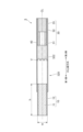
- FIG. 7 is a view showing a longitudinal section of the stick 3 according to the third embodiment.
- the stick 3 according to the third embodiment differs from the stick 1 described above in the cooling section 320 corresponding to the cooling section 20 . Differences from the first embodiment will be described below.
- the same reference numerals are used for the same components as in the first embodiment, and detailed description thereof will be omitted.
- the cooling section 320 differs from the stick 1 in that it does not have a member corresponding to the forming paper 21 .
- the cooling part 320 is a space formed inside the stick 3, and is a cylindrical space surrounded by the second side surface of the base material part 10, the first side surface of the filter part 30, and the chipping paper 40. be.
- the cooling part 320 has an opening V through which air flows from the outside to the inside, and a heat exchanging material 322 on the opposite side of the opening V from the base material part 10 .
- the heat exchange material 322 is the same as the heat exchange material 22.
- the heat exchange article 322 may be the same as the heat exchange article 222 .
- the stick 3 includes the base portion 10 including the aerosol source 11 and the cylindrical cooling portion 320 that cools vapor generated by heating the base portion 10 to generate aerosol.
- the cooling part 320 has an opening V through which air flows into the inside from the outside, and a coating capable of exchanging heat with the aerosol on the side opposite to the base part 10 with respect to the opening V inside A heat exchanging material 322 forming a layer is provided, and is not provided on the base member 10 side of the opening V.
- the stick 3 similarly to the stick 1, it is possible to adjust the temperature or flavor of the aerosol while maintaining the delivery amount of the product.
- the cooling section 320 is a space formed between the base material section 10 and the filter section 30 by the tip paper 40 .
- the tip paper 40 makes the volume smaller than the space formed between the base material part 10 and the filter part 30 .
Landscapes
- Cigarettes, Filters, And Manufacturing Of Filters (AREA)
Abstract
Un bâton de type chauffage sans combustion (1) comprend une partie de matériau de base (10) contenant une source d'aérosol (11) et une partie de refroidissement tubulaire (20) permettant de refroidir la vapeur générée par chauffage de la partie de matériau de base (10) afin de générer un aérosol : la partie de refroidissement (20) possédant une ouverture V à travers laquelle de l'air s'écoule de l'extérieur à l'intérieur ; et, à l'intérieur de celle-ci, un échangeur thermique (22), pouvant échanger de la chaleur avec l'aérosol ou conférer un arôme à l'aérosol, étant formé sur le côté opposé de la partie de matériau de base (10) par rapport à l'ouverture V, et non pas sur le côté de la partie de matériau de base (10) par rapport à l'ouverture V.
Priority Applications (1)
| Application Number | Priority Date | Filing Date | Title |
|---|---|---|---|
| PCT/JP2021/044125 WO2023100295A1 (fr) | 2021-12-01 | 2021-12-01 | Bâton de type chauffage sans combustion |
Applications Claiming Priority (1)
| Application Number | Priority Date | Filing Date | Title |
|---|---|---|---|
| PCT/JP2021/044125 WO2023100295A1 (fr) | 2021-12-01 | 2021-12-01 | Bâton de type chauffage sans combustion |
Publications (1)
| Publication Number | Publication Date |
|---|---|
| WO2023100295A1 true WO2023100295A1 (fr) | 2023-06-08 |
Family
ID=86611653
Family Applications (1)
| Application Number | Title | Priority Date | Filing Date |
|---|---|---|---|
| PCT/JP2021/044125 Ceased WO2023100295A1 (fr) | 2021-12-01 | 2021-12-01 | Bâton de type chauffage sans combustion |
Country Status (1)
| Country | Link |
|---|---|
| WO (1) | WO2023100295A1 (fr) |
Citations (5)
| Publication number | Priority date | Publication date | Assignee | Title |
|---|---|---|---|---|
| JPH07278961A (ja) * | 1994-04-06 | 1995-10-24 | Japan Tobacco Inc | 香料保留性複合繊維およびこれを用いた喫煙用フィルタ並びに喫煙用パイプ |
| JP2014508201A (ja) * | 2011-01-28 | 2014-04-03 | アール・ジエイ・レイノルズ・タバコ・カンパニー | タバコに由来するポリマー材料 |
| JP2016158598A (ja) * | 2015-03-04 | 2016-09-05 | 株式会社ダイセル | たばこフィルタ及びたばこ、並びにフィルタの変色方法 |
| JP2018082711A (ja) * | 2012-05-31 | 2018-05-31 | フィリップ・モーリス・プロダクツ・ソシエテ・アノニム | エアロゾル発生物品で使用するための熱伝導ロッド |
| WO2020115898A1 (fr) * | 2018-12-07 | 2020-06-11 | 日本たばこ産業株式会社 | Article à fumer de type chauffant non combustible et système à fumer de type chauffant électrique |
-
2021
- 2021-12-01 WO PCT/JP2021/044125 patent/WO2023100295A1/fr not_active Ceased
Patent Citations (5)
| Publication number | Priority date | Publication date | Assignee | Title |
|---|---|---|---|---|
| JPH07278961A (ja) * | 1994-04-06 | 1995-10-24 | Japan Tobacco Inc | 香料保留性複合繊維およびこれを用いた喫煙用フィルタ並びに喫煙用パイプ |
| JP2014508201A (ja) * | 2011-01-28 | 2014-04-03 | アール・ジエイ・レイノルズ・タバコ・カンパニー | タバコに由来するポリマー材料 |
| JP2018082711A (ja) * | 2012-05-31 | 2018-05-31 | フィリップ・モーリス・プロダクツ・ソシエテ・アノニム | エアロゾル発生物品で使用するための熱伝導ロッド |
| JP2016158598A (ja) * | 2015-03-04 | 2016-09-05 | 株式会社ダイセル | たばこフィルタ及びたばこ、並びにフィルタの変色方法 |
| WO2020115898A1 (fr) * | 2018-12-07 | 2020-06-11 | 日本たばこ産業株式会社 | Article à fumer de type chauffant non combustible et système à fumer de type chauffant électrique |
Similar Documents
| Publication | Publication Date | Title |
|---|---|---|
| JP7313437B2 (ja) | 非燃焼加熱式たばこ及び電気加熱式たばこ製品 | |
| WO2021172255A1 (fr) | Système pour fumer | |
| TWI904359B (zh) | 非燃燒加熱式香味吸嚐物品及非燃燒加熱式香味吸嚐製品 | |
| JP7522864B2 (ja) | 非燃焼加熱式たばこ及び電気加熱式たばこ製品 | |
| WO2023100295A1 (fr) | Bâton de type chauffage sans combustion | |
| JP7522863B2 (ja) | 非燃焼加熱式たばこ及び電気加熱式たばこ製品 | |
| JP7659576B2 (ja) | 非燃焼加熱式たばこ及び電気加熱式たばこ製品 | |
| JP7640582B2 (ja) | 非燃焼加熱式たばこ及び電気加熱式たばこ製品 | |
| TWI914801B (zh) | 香味吸嚐物品 | |
| WO2025154253A1 (fr) | Article de génération d'arôme | |
| TW202510762A (zh) | 香味產生物品及香味產生系統 | |
| WO2025154254A1 (fr) | Article de génération d'arôme, et procédé de fabrication de celui-ci | |
| WO2025154255A1 (fr) | Système d'inhalation d'arôme | |
| WO2025186891A1 (fr) | Article de génération d'arôme | |
| WO2025126308A1 (fr) | Article de génération d'arôme | |
| JP2025135077A (ja) | 香味発生物品 | |
| WO2025052625A1 (fr) | Article de génération d'arôme | |
| WO2025186899A1 (fr) | Article d'inhalation d'arôme | |
| WO2025243507A1 (fr) | Article de génération d'arôme et système de génération d'arôme | |
| TW202508474A (zh) | 香味吸嚐物品 | |
| KR20260041137A (ko) | 향미 생성 물품 | |
| TW202508475A (zh) | 非燃燒型香味吸嚐物品及非燃燒型香味吸嚐系統 | |
| WO2025052618A1 (fr) | Article de génération d'arôme et système à fumer | |
| WO2023084770A1 (fr) | Bâtonnet chauffé sans combustion | |
| WO2025186900A1 (fr) | Article d'inhalation d'arôme |
Legal Events
| Date | Code | Title | Description |
|---|---|---|---|
| 121 | Ep: the epo has been informed by wipo that ep was designated in this application |
Ref document number: 21966379 Country of ref document: EP Kind code of ref document: A1 |
|
| NENP | Non-entry into the national phase |
Ref country code: DE |
|
| 122 | Ep: pct application non-entry in european phase |
Ref document number: 21966379 Country of ref document: EP Kind code of ref document: A1 |
|
| NENP | Non-entry into the national phase |
Ref country code: JP |