WO2023100797A1 - 案内装置 - Google Patents
案内装置 Download PDFInfo
- Publication number
- WO2023100797A1 WO2023100797A1 PCT/JP2022/043741 JP2022043741W WO2023100797A1 WO 2023100797 A1 WO2023100797 A1 WO 2023100797A1 JP 2022043741 W JP2022043741 W JP 2022043741W WO 2023100797 A1 WO2023100797 A1 WO 2023100797A1
- Authority
- WO
- WIPO (PCT)
- Prior art keywords
- rail
- mounting
- bolt
- hole
- recess
- Prior art date
- Legal status (The legal status is an assumption and is not a legal conclusion. Google has not performed a legal analysis and makes no representation as to the accuracy of the status listed.)
- Ceased
Links
Images












Classifications
-
- F—MECHANICAL ENGINEERING; LIGHTING; HEATING; WEAPONS; BLASTING
- F16—ENGINEERING ELEMENTS AND UNITS; GENERAL MEASURES FOR PRODUCING AND MAINTAINING EFFECTIVE FUNCTIONING OF MACHINES OR INSTALLATIONS; THERMAL INSULATION IN GENERAL
- F16C—SHAFTS; FLEXIBLE SHAFTS; ELEMENTS OR CRANKSHAFT MECHANISMS; ROTARY BODIES OTHER THAN GEARING ELEMENTS; BEARINGS
- F16C29/00—Bearings for parts moving only linearly
- F16C29/04—Ball or roller bearings
- F16C29/06—Ball or roller bearings in which the rolling bodies circulate partly without carrying load
-
- F—MECHANICAL ENGINEERING; LIGHTING; HEATING; WEAPONS; BLASTING
- F16—ENGINEERING ELEMENTS AND UNITS; GENERAL MEASURES FOR PRODUCING AND MAINTAINING EFFECTIVE FUNCTIONING OF MACHINES OR INSTALLATIONS; THERMAL INSULATION IN GENERAL
- F16C—SHAFTS; FLEXIBLE SHAFTS; ELEMENTS OR CRANKSHAFT MECHANISMS; ROTARY BODIES OTHER THAN GEARING ELEMENTS; BEARINGS
- F16C29/00—Bearings for parts moving only linearly
- F16C29/004—Fixing of a carriage or rail, e.g. rigid mounting to a support structure or a movable part
-
- F—MECHANICAL ENGINEERING; LIGHTING; HEATING; WEAPONS; BLASTING
- F16—ENGINEERING ELEMENTS AND UNITS; GENERAL MEASURES FOR PRODUCING AND MAINTAINING EFFECTIVE FUNCTIONING OF MACHINES OR INSTALLATIONS; THERMAL INSULATION IN GENERAL
- F16C—SHAFTS; FLEXIBLE SHAFTS; ELEMENTS OR CRANKSHAFT MECHANISMS; ROTARY BODIES OTHER THAN GEARING ELEMENTS; BEARINGS
- F16C29/00—Bearings for parts moving only linearly
- F16C29/001—Bearings for parts moving only linearly adjustable for alignment or positioning
-
- F—MECHANICAL ENGINEERING; LIGHTING; HEATING; WEAPONS; BLASTING
- F16—ENGINEERING ELEMENTS AND UNITS; GENERAL MEASURES FOR PRODUCING AND MAINTAINING EFFECTIVE FUNCTIONING OF MACHINES OR INSTALLATIONS; THERMAL INSULATION IN GENERAL
- F16C—SHAFTS; FLEXIBLE SHAFTS; ELEMENTS OR CRANKSHAFT MECHANISMS; ROTARY BODIES OTHER THAN GEARING ELEMENTS; BEARINGS
- F16C29/00—Bearings for parts moving only linearly
- F16C29/005—Guide rails or tracks for a linear bearing, i.e. adapted for movement of a carriage or bearing body there along
-
- F—MECHANICAL ENGINEERING; LIGHTING; HEATING; WEAPONS; BLASTING
- F16—ENGINEERING ELEMENTS AND UNITS; GENERAL MEASURES FOR PRODUCING AND MAINTAINING EFFECTIVE FUNCTIONING OF MACHINES OR INSTALLATIONS; THERMAL INSULATION IN GENERAL
- F16C—SHAFTS; FLEXIBLE SHAFTS; ELEMENTS OR CRANKSHAFT MECHANISMS; ROTARY BODIES OTHER THAN GEARING ELEMENTS; BEARINGS
- F16C2226/00—Joining parts; Fastening; Assembling or mounting parts
- F16C2226/50—Positive connections
- F16C2226/60—Positive connections with threaded parts, e.g. bolt and nut connections
Definitions
- the present invention relates to a guide device.
- a guide device in which rails for guiding the carriage are arranged is known.
- this guide device there is known a technique of improving the straightness by correcting the bending of the rail using an eccentric bolt (see Patent Document 1, for example).
- a single rail may be constructed by connecting divided rails.
- vibration may occur when the carriage passes.
- two reference surfaces surfaces abutting against the bottom surface of the rail and the side surface of the rail, respectively
- the rails are connected to each other using a vice or bolt.
- the rail mounting parts are also divided.
- a step may occur at the connecting portion of the rail.
- it is necessary to make fine adjustments such as inserting a step shim between the rail and the reference surface, but such work is very complicated and takes time.
- the present invention has been made in view of the various circumstances as described above, and its object is to reduce the deviation of the joints of the rails and to move the carriage more smoothly.
- One aspect of the present invention is a first surface in contact with the mounting surface; a second surface facing the first surface; a through hole penetrating between the first surface and the second surface; a recess that is an opening of the through-hole on the first surface side and that is recessed from the first surface toward the second surface;
- a guide device comprising a rail having the recess includes a third surface orthogonal to the first surface and orthogonal to the width direction of the rail;
- An eccentric portion that rotates eccentrically with respect to a reference axis orthogonal to the mounting surface and applies force to the third surface in the width direction of the rail is housed in the recess,
- the diameter of the through hole is shorter than the length of the recess in the width direction, It is a guide device.
- FIG. 6 is a cross-sectional view taken along the line AA of FIG.
- FIG. 5 is an enlarged view of the vicinity of the eccentric bolt in the AA cross section of FIG. 5 according to the first embodiment;
- FIG. 4 is a cross-sectional view of the vicinity of the eccentric bolt according to the first embodiment taken along a plane (XZ plane) perpendicular to the Y-axis;
- FIG. 4 is a cross-sectional view of the vicinity of the eccentric bolt according to the first embodiment taken along a plane (YZ plane) perpendicular to the X axis;
- FIG. 4 is a schematic diagram showing the state of the rail before a pressing force acts on the bolt contact surface in the Y-axis direction from the head of the eccentric bolt according to the first embodiment;
- FIG. 4 is a schematic diagram showing a state of the rail after a pressing force acts on the bolt contact surface in the Y-axis direction from the head of the eccentric bolt according to the first embodiment;
- FIG. 11 is a perspective view of the lower surface side of the second rail according to the second embodiment;
- FIG. 12 is a perspective view of the upper surface side of the rail according to the third embodiment; It is a perspective view of the lower surface side of the rail which concerns on 3rd Embodiment. It is sectional drawing in the state which attached the rail which concerns on 3rd Embodiment to the attachment member.
- FIG. 4 is a schematic diagram showing the state of the rail before a pressing force acts on the bolt contact surface in the Y-axis direction from the head of the eccentric bolt according to the first embodiment
- FIG. 11 is a perspective view of
- FIG. 11 is a cross-sectional view of the adjustment hole according to the third embodiment taken along a plane (YZ plane) orthogonal to the X-axis direction; It is a perspective view of the upper surface side of the rail which concerns on 4th Embodiment. It is a perspective view of the lower surface side of the rail which concerns on 4th Embodiment. It is the figure which showed an example of the side view of the rail which concerns on 5th Embodiment. It is the figure which showed an example when the rail which concerns on 5th Embodiment is seen from upper direction. It is the figure which showed an example when the rail which concerns on 5th Embodiment is seen from the downward direction.
- FIG. 21 is an example of a perspective view of a top side of a state in which the first rail and the second rail are connected according to the fifth embodiment; It is the figure which showed an example when the rail and carriage which concern on 5th Embodiment are seen from the back side. It is the figure which showed an example of the side view of the rail and carriage which concern on 5th Embodiment.
- FIG. 11 is a diagram showing an example of a connection portion of rails according to a fifth embodiment; It is the figure which showed an example of the side view of the rail which concerns on 6th Embodiment. It is the figure which showed an example when the rail which concerns on 6th Embodiment is seen from upper direction.
- FIG. 21 is an example of a perspective view of the upper surface side of a state in which the first rail and the second rail are connected according to the sixth embodiment;
- a guide device which is one aspect of the present invention, includes a rail.
- a rail is attached to the mounting surface and guides the carriage.
- the first surface is the surface that contacts the mounting surface when the rail is mounted on the mounting surface.
- the rail also has a second surface facing the first surface.
- the first surface and the second surface are surfaces extending in the longitudinal direction of the rail. In addition, the second surface does not have to be parallel to the first surface.
- the rail has a through hole.
- the through hole has a center axis perpendicular to the first surface and the mounting surface. A tool, for example, can be passed through this through hole.
- the rail has a recess that is an opening on the first surface side of the through hole and that is recessed from the first surface toward the second surface. That is, the through hole is open at the recess. Since the recess is recessed from the first surface, a space surrounded by the recess and the mounting surface is formed when the rail is attached to the mounting surface.
- the recess includes a third surface orthogonal to the first surface and orthogonal to the width direction of the rail.
- This third surface is a surface formed in the side surface direction of the rail among the surfaces forming the recess.
- This third surface may be a surface parallel to the side surface of the rail.
- the recess accommodates an eccentric portion that rotates eccentrically with respect to a reference axis orthogonal to the mounting surface and applies force to the third surface in the width direction of the rail.
- the reference axis is a rotation axis provided on the mounting surface.
- the eccentric portion pushes the third surface by contacting the eccentric portion with the third surface.
- the rail is elastically deformed and bent by the force with which the eccentric portion presses the third surface. Since the eccentric portion is eccentric with respect to the reference axis, the force pressing the third surface can be adjusted by adjusting the rotation angle. Therefore, the bending of the rail can be corrected by rotating the eccentric portion.
- the through hole and the recess are formed such that the diameter of the through hole is shorter than the length of the recess in the width direction. Therefore, since the diameter of the through hole is relatively small, for example, when a tool for rotating the eccentric portion is inserted into the through hole, the tool can be easily inserted into the eccentric portion. Therefore, it is possible to rotate the eccentric portion quickly, and elastically deform the ends of the rails, thereby reducing the displacement of the joints of the rails.
- the eccentric portion may be the head of an eccentric bolt that rotates around the reference axis.
- the threaded portion of the bolt is screwed into the mounting surface. If it is an eccentric bolt, it will not come off even if it is attached to the mounting surface in advance, so the work can be simplified. Also, if there is a tool for turning the eccentric bolt, the bending of the rail can be corrected relatively easily.
- the recess may be formed up to at least one end of the rail. Then, for example, it becomes possible to store the eccentric portion in the recess while moving the rail in the longitudinal direction, so that the work can be simplified.
- the through-hole may be formed closer to the end of the rail than the mounting hole through which the bolt for fixing the rail to the mounting surface is passed. For example, if force is applied to the third surface by the eccentric part to correct the bending of the rail, and the rail is attached to the mounting surface with a bolt passed through the mounting hole, the rail can be fixed in a state where the bending of the rail is corrected. can be done. In addition, since the through hole is provided on the end side of the rail, even if there is a step with another rail when connecting to another rail, the rail can be bent in a direction that eliminates the step by rotating the eccentric part. be able to.
- the through holes may be formed between a plurality of mounting holes through which bolts for fixing the rail to the mounting surface are passed.
- FIG. 1 is a diagram showing the appearance of a guide device 1 according to this embodiment.
- the guide device 1 includes a rail 12 and a carriage 50 assembled along the longitudinal direction of the rail 12 so as to be relatively movable.
- the rail 12 is attached to a mounting surface of user equipment such as a machine tool, and a table of the user equipment is attached to the carriage 50 .
- the movement of the movable part, including the table is guided by the guiding device 1 .
- the guide device 1 may be used in a state in which the longitudinal direction of the rail 12 is not horizontal, but inclined or perpendicular to the horizontal plane.
- the rail 12 is arranged on a horizontal plane for convenience of explanation.
- an XYZ orthogonal coordinate system is set, and the position of each member will be described with reference to this XYZ orthogonal coordinate system.
- the configuration of the guide device 1 will be described with the direction viewed from the longitudinal direction of the rail 12, that is, the X-axis direction shown in FIG.
- the arrangement of the guide device 1 is not limited to such an arrangement.
- FIG. 2 is a diagram showing movements of the plurality of rollers 53 in the guide device 1 according to this embodiment.
- FIG. 3 is a diagram showing a cross section of the guide device 1 on a plane (YZ plane in FIG. 1) orthogonal to the longitudinal direction of the rail 12 according to this embodiment.
- two upper and lower rolling surfaces 1241 are formed on each of the left and right side surfaces 124 of the rail 12 . That is, the rail 12 is formed with four rolling surfaces 1241 .
- the carriage 50 has a central portion facing the upper surface 122, which is the upper surface of the rail 12, and a pair of side portions facing the side surfaces of the rail 12, and has a U-shaped cross section.
- the carriage 50 includes a carriage body 51 at the center in the movement direction, and a pair of end plates 52 arranged at both ends of the carriage body 51 in the movement direction.
- the carriage body 51 has a central portion 511 facing the top surface 122 of the rail 12 and a pair of side portions 512 facing the side surfaces 124 of the rail 12. It is glyph-shaped.
- the end plate 52 also has a central portion facing the upper surface 122 of the rail 12 and a pair of side portions facing the side surfaces 124 of the rail 12, and has a U-shaped cross section. is.
- Each end plate 52 is fastened to the carriage body 51 by fastening members such as bolts.
- the carriage body 51 is formed with four rolling surfaces 1242 that face the four rolling surfaces 1241 of the rail 12 respectively.
- a plurality of rollers 53 are rotatably sandwiched between a rolling surface 1241 formed on the rail 12 and a rolling surface 1242 formed on the carriage body 51 so that the carriage body 51 is attached to the rail 12 . engaged.
- a load rolling path 54 is defined by the rolling surface 1241 of the rail 12 and the rolling surface 1242 of the carriage body 51 that face each other.
- a return path 55 is formed in parallel with the load rolling path 54 inside the carriage body 51 .
- each end plate 52 is formed with a U-shaped turning path 56 that connects the load rolling path 54 and the return path 55 .
- the inner peripheral side of the direction change path 56 is constituted by an inner peripheral portion 57 integral with the carriage body 51 and having a semicircular cross section.
- a track-shaped rolling element path 58 is formed by the load rolling path 54 between the rolling surface 1241 of the rail 12 and the rolling surface 1242 of the carriage body 51 , the pair of direction change paths 56 and the return path 55 .
- a plurality of rollers 53 are accommodated in this rolling element path 58 .
- the plurality of rollers 53 pass through the rolling element paths 58. Circulates in the direction of That is, the rollers 53 existing between the rolling surfaces 1241 and 1242 facing each other roll on the load rolling path 54 . Further, the roller 53 that has rolled to one end of the load rolling path 54 is introduced into one direction changing path 56 and returns to the other end of the load rolling path 54 via the return path 55 and the other direction changing path 56. .
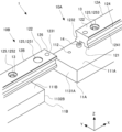
- FIG. 4 is a diagram showing an example of a schematic configuration of the guide device 1 before connecting the rails 12 according to the first embodiment.
- the guiding device 1 has a first module 10A and a second module 10B.
- the first module 10A includes a first mounting member 11A and a first rail 12A fixed to the mounting surface 111A of the first mounting member 11A.
- the second module 10B includes a second mounting member 11B and a second rail 12B fixed to the mounting surface 111B of the second mounting member 11B.
- the 1st module 10A and the 2nd module 10B are the same shapes. However, the shape is not limited to this, and the first module 10A and the second module 10B may have different shapes.
- first mounting member 11A and the second mounting member 11B are not distinguished, they are simply referred to as the mounting member 11, and the mounting surface 111A of the first mounting member 11A and the mounting surface 111B of the second mounting member 11B are distinguished. Otherwise, it is simply referred to as the mounting surface 111 .
- the mounting surface 111 is the mounting surface of the user equipment described above.
- rails 12 when not distinguishing between the first rail 12A and the second rail 12B, they will simply be referred to as rails 12 .
- a mounting surface 111 of the mounting member 11 is a surface to which the rail 12 is attached and fixed.
- the direction orthogonal to the mounting surface 111 is the Z-axis direction
- the longitudinal direction of the rail 12 on the mounting surface 111 is the X-axis direction
- the lateral direction of the rail 12 on the mounting surface 111 is the Y-axis direction.
- the first module 10A side is the front side
- the second module 10B side is the rear side
- the rail 12 side is the upper side
- the mounting member 11 side is the lower side.
- the Y-axis direction is also referred to as the width direction.
- the surface of the rail 12 that is in contact with the mounting member 11 (the surface that faces downward) and that faces the upper surface 122 is referred to as a lower surface 121 .
- the lower surface 121 and the upper surface 122 are surfaces perpendicular to the Z-axis direction.
- the upper surface 122 is not limited to this, and may be a surface that is inclined with respect to the Z-axis direction.
- the lower surface 121 is an example of a first surface
- the upper surface 122 is an example of a second surface.
- a surface (an end surface in the X-axis direction) where the rails 12 are in contact when the rails 12 are connected to each other is called an end surface 123 .
- the end face 123 on the front side in the X-axis direction is called a front end face 1231
- the end face 123 on the rear side in the X-axis direction is called a rear end face 1232 .
- the front end surface 1231 and the rear end surface 1232 are described as surfaces orthogonal to the X-axis direction, but the present invention is not limited to this, and may be surfaces having an acute or obtuse angle with respect to the X-axis direction, for example.
- FIG. 4 shows the state before the front end surface 1231 of the second rail 12B is connected to the rear end surface 1232 of the first rail 12A.
- the rail 12 is formed with a bolt mounting hole 125 which is a through hole through which the mounting bolt 13 for fixing to the mounting surface 111 passes.
- the bolt mounting holes 125 are formed in the Z-axis direction.
- a plurality of bolt mounting holes 125 are provided in each rail 12 in the X-axis direction.
- a counterbore is formed on the upper surface 122 side of the bolt mounting hole 125 so that the head of the mounting bolt 13 is stored in the rail 12 .
- the mounting member 11 is formed with a screw hole 112 in the Z-axis direction into which the mounting bolt 13 is screwed.
- the screw holes 112 are formed vertically from the mounting surface 111 at positions corresponding to the bolt mounting holes 125 of the rail 12 .
- FIG. 5 is a diagram showing an example of a side view after connecting the first module 10A and the second module 10B according to the first embodiment.
- FIG. 5 is a view of the guide device 1 viewed from the Y-axis direction.
- FIG. 6 is a cross-sectional view taken along line AA in FIG. 5 according to the first embodiment.
- the rear end surface 1232 of the first rail 12A is shifted forward from the rear end surface 1131A of the first mounting member 11A.
- the front end surface 1231 of the second rail 12B is shifted forward from the front end surface 1132B of the second mounting member 11B.
- a bolt mounting hole 125 on the frontmost side of the second rail 12B in the second module 10B is provided at a position protruding from the second mounting member 11B.
- the bolt mounting hole 125 on the frontmost side of the rail 12 is hereinafter referred to as the first bolt mounting hole 1251 .
- the mounting member 11 is formed with screw holes 112 corresponding to the second and subsequent bolt mounting holes 125 from the front side of the rail 12, into which the mounting bolts 13 are inserted.
- the second bolt mounting hole 125 from the front side of the rail 12 is hereinafter referred to as a second bolt mounting hole 1252 .
- the second rail 12B is fixed to the second mounting member 11B by mounting bolts 13 inserted into the plurality of bolt mounting holes 125 after the second bolt mounting hole 1252 .
- the mounting bolts 13 are inserted into the bolt mounting holes 125 on the rearmost side of the first rail 12A.
- a mounting bolt 13 is inserted.
- the bolt mounting hole 125 on the rearmost side of the rail 12 is hereinafter referred to as a third bolt mounting hole 1253 .
- the first rail 12A is fixed to the first mounting member 11A by mounting bolts 13 inserted into a plurality of bolt mounting holes 125 from a second bolt mounting hole 1252 to a third bolt mounting hole 1253. As shown in FIG.
- FIG. 7 is a view of the second rail 12B according to the first embodiment viewed from the bottom surface 121 side.
- the adjustment hole 126 is formed in the Z-axis direction.
- a recess 1260 recessed from the lower surface 121 of the second rail 12B toward the upper surface 122 is formed in the opening of the adjustment hole 126 on the lower surface 121 side.
- the end of the recess 1260 in the X-axis direction opens to the front end surface 1231 of the second rail 12B.
- the recess 1260 is formed from the front end face 1231 toward the rear end face 1232 in the X-axis direction.
- the recess 1260 accommodates the head 141 of the eccentric bolt 14 .
- the head 141 of the eccentric bolt 14 is an example of an eccentric portion.
- an adjustment hole 126 which is a through hole, is also formed on the rear end surface 1232 side of the third bolt mounting hole 1253, and a recess 1260 is formed. These are not absolutely necessary.
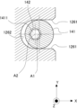
- FIG. 8 is an enlarged view of the vicinity of the eccentric bolt 14 in the AA section of FIG. 5 according to the first embodiment.
- FIG. 9 is a cross-sectional view of the vicinity of the eccentric bolt 14 according to the first embodiment taken along a plane (XZ plane) perpendicular to the Y-axis.
- FIG. 10 is a cross-sectional view of the vicinity of the eccentric bolt 14 according to the first embodiment taken along a plane (YZ plane) perpendicular to the X axis.
- the concave portion 1260 has a bolt contact surface 1261 that is two planes orthogonal to the Y axis and parallel to each other, and protrudes from the bolt contact surface 1261 toward the rear end surface 1232 with the two bolt contact surfaces 1261 as contact surfaces.
- the distance between the two bolt contact surfaces 1261 is longer than the diameter of the adjustment hole 126. That is, the diameter of the adjustment hole 126 is shorter than the length of the recess 1260 in the width direction (Y-axis direction). Also, the distance between the two bolt contact surfaces 1261 is slightly longer than the diameter of the head 141 of the eccentric bolt 14, and is formed so that the head 141 of the eccentric bolt 14 is stored. On the other hand, the diameter of the adjustment hole 126 is formed to be shorter than the diameter of the head 141 of the eccentric bolt 14 and longer than the width (or diameter) of the tool 30 for turning the eccentric bolt 14. .
- Tool 30 is, for example, a hexagonal wrench.
- the eccentric bolt 14 is attached to the first attachment member 11A.
- An adjusting screw hole 114 corresponding to the eccentric bolt 14 is formed in the first mounting member 11A.
- the central axis of this adjustment screw hole 114 is located on the same plane as the central axis of the screw hole 112 of the mounting bolt 13 .
- the adjustment holes are arranged such that the distance from the rear end surface 1232 of the first rail 12A to the center axis of the adjustment screw hole 114 is substantially equal to the distance from the front end surface 1231 of the second rail 12B to the center axis of the adjustment hole 126.
- 126 and adjustment screw holes 114 are formed.
- a threaded hole 112 corresponding to the first bolt mounting hole 1251 of the second rail 12B is formed in the first mounting member 11A.
- the distance from the rear end surface 1232 of the first rail 12A to the central axis of the screw hole 112 is substantially equal to the distance from the front end surface 1231 of the second rail 12B to the central axis of the first bolt mounting hole 1251. , a first bolt mounting hole 1251 and a threaded hole 112 corresponding thereto are formed.
- the eccentric bolt 14 has a head 141 and a threaded portion 142 connected to the head 141 and formed with threads.
- the eccentric bolt 14 is formed such that the central axis A1 of the head portion 141 is displaced from the central axis A2 of the threaded portion 142 .
- the eccentric bolt 14 is, for example, a hexagonal socket head bolt, and has a cylindrical head 141 with a hexagonal columnar hole (hereinafter also referred to as a hexagonal hole 1411).
- the central axis of the hexagonal hole 1411 is positioned on the central axis of the threaded portion 142, for example.
- the eccentric bolt 14 is attached to the first attachment member 11A before the first module 10A and the second module 10B are connected.
- the recess 1260 is formed such that the distance from the lower surface 121 of the second rail 12B to the bottom surface 1263 is longer than the length of the head 141 of the eccentric bolt 14 in the central axis A1 direction. Also, the recess 1260 is such that the distance between the two bolt contact surfaces 1261 is longer than the diameter of the head 141 of the eccentric bolt 14 and the diameter of the head 141 of the eccentric bolt 14 is equal to the threaded portion 142 of the eccentric bolt 14 .
- the head 141 is formed to be shorter than the sum of the distance from the central axis A2 of the head 141 to the central axis A1 of the head 141 .
- the head 141 of the eccentric bolt 14 can be housed in the recess 1260, and when the eccentric bolt 14 is rotated, the side surface of the head 141 contacts the bolt contact surface 1261. Upon contact, the head 141 can push the bolt contact surface 1261 in the Y-axis direction.
- the head of the eccentric bolt 14 When attaching the eccentric bolt 14 to the first mounting member 11A, the head of the eccentric bolt 14 is mounted so that a plane including the central axis A2 of the threaded portion 142 and the central axis A1 of the head 141 is orthogonal to the Y-axis direction. 141 angle is adjusted. This allows the head 141 of the eccentric bolt 14 to be stored in the recess 1260 when connecting the second module 10B to the first module 10A.
- the second rail 12B is placed on the mounting surface 111A of the first mounting member 11A. At this time, the second rail 12B may be shifted in the X-axis direction and placed on the mounting surface 111A of the first mounting member 11A. You can put it.
- the mounting bolt 13 is temporarily tightened into the first bolt mounting hole 1251 of the second rail 12B. At this time, the mounting bolt 13 is temporarily tightened with a torque that allows the second rail 12B to move in the Y-axis direction.
- the first mounting member 11A and the second mounting member 11B may be fixed to other base members by bolts or the like, or the first mounting member 11A and the second mounting member 11B may be connected to each other by bolts or the like. good.
- the fixing method of the first mounting member 11A and the second mounting member 11B is not limited.
- the tool 30 is operated to move the eccentric bolt 14 to the central axis A2 of the threaded portion 142.
- a pressing force acts on one bolt contact surface 1261 in the Y-axis direction.
- the second rail 12B is bent in the direction of the pressing force.
- the rotation angle of the eccentric bolt 14 is adjusted using a micrometer so that the step between the side surface 124 of the first rail 12A and the side surface 124 of the second rail 12B is equal to or less than a predetermined value.
- the mounting bolt 13 temporarily tightened in the first bolt mounting hole 1251 of the second rail 12B is removed.
- the second rail 12B is fixed to the first mounting member 11A.
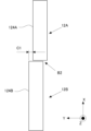
- FIG. 11 is a schematic diagram showing the state of the rail 12 before a pressing force acts on the bolt contact surface 1261 from the head 141 of the eccentric bolt 14 according to the first embodiment in the Y-axis direction.
- FIG. 12 is a schematic diagram showing the state of the rail 12 after a pressing force acts on the bolt contact surface 1261 in the Y-axis direction from the head 141 of the eccentric bolt 14 according to the first embodiment.
- 11 and 12 are views of the rail 12 viewed from the upper surface 122 side.
- the side surface 124A of the first rail 12A and the side surface 124B of the second rail 12B contact each other at the connecting portion B2 of the rail 12. , are displaced in the Y-axis direction by a distance indicated by C1.
- the second rail 12B elastically deforms due to this pressing force, and the tip moves in the Y-axis direction. It is As a result, the deviation in the Y-axis direction between the side surface 124A of the first rail 12A and the side surface 124B of the second rail 12B at the connecting portion B2 of the rail 12 is reduced to the distance indicated by C2.
- the bending of the rail 12 can be corrected. can be reduced. Thereby, it is possible to suppress the occurrence of a step at the connection portion B2 of the rail 12 . Therefore, the carriage can be moved more smoothly.
- the second rail 12B is moved in the longitudinal direction (X-axis direction) while the front end face 1231 of the second rail 12B is moved to the first position. It can be brought into contact with the rear end face 1232 of the rail 12A.
- the eccentric bolt 14 By attaching the eccentric bolt 14 to the first attachment member 11A in advance, positioning when connecting the second rail 12B is facilitated.
- the diameter of the adjustment hole 126 By making the diameter of the adjustment hole 126 shorter than the width of the recess 1260 in the Y-axis direction, the tool 30 can easily enter the hexagonal hole 1411 of the head 141 . Therefore, it becomes easier to rotate the eccentric bolt 14 after the second rail 12B is brought into contact with the first rail 12A. For example, if there is an obstacle above the first rail 12A and the second rail 12B, the adjustment hole 126 may not be visible when tightening the eccentric bolt 14 later. In such a case, the adjustment hole 126 is checked by hand and the tool 30 is inserted. can be difficult. With the adjustment hole 126 according to the first embodiment, the tool 30 can be easily inserted into the hexagonal hole 1411 of the eccentric bolt 14, so the rail 12 can be corrected more quickly.
- the recess 1260 is formed up to the front end surface 1231 of the second rail 12B, but in the second embodiment, the recess 1260A is formed so as not to reach the front end surface 1231 of the second rail 12B.
- FIG. 13 is a perspective view of the lower surface 121 side of the second rail 12B according to the second embodiment.
- the recessed portion 1260 is formed so that the cross section when cut along a plane perpendicular to the Z-axis direction is an elongated hole.
- Two bolt contact surfaces 1261A which are two planes perpendicular to the Y-axis direction and parallel to each other, are formed. Equal to the distance between faces 1261 .
- the configuration other than the shape of the recess 1260A on the front end surface 1231 side is the same as that of the first embodiment. Therefore, the distance between the two bolt contact surfaces 1261A is longer than the diameter of the adjustment hole 126.
- the tool 30 can be easily inserted into the hexagonal hole 1411, so the rail can be corrected more quickly. Further, by forming the cross-sectional shape of the recess 1260A into an elongated hole, deformation of the recess 1260 when force is applied to the recess 1260 from the eccentric bolt 14 can be suppressed.
- FIG. 14 is a perspective view of the upper surface 122 side of the rail 12 according to the third embodiment
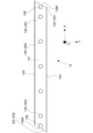
- FIG. 15 is a perspective view of the lower surface 121 side of the rail 12 according to the third embodiment
- FIG. 16 is a cross-sectional view of the rail 12 according to the third embodiment attached to the mounting member 11. As shown in FIG.
- a plurality of bolt mounting holes 125 and a plurality of adjustment holes 126 are alternately formed in the rail 12 in the longitudinal direction of the rail.
- the bolt mounting holes 125 and the adjustment holes 126 may be alternately arranged at regular intervals.
- an adjustment hole 126 may be formed for each predetermined number of bolt mounting holes 125 .
- the shape of the bolt mounting hole 125 is the same as the shape of the bolt mounting hole 125 according to the first embodiment.
- a plurality of adjustment holes 126 communicate with recesses 1260A on the lower surface 121 side, respectively.
- the shape of the recess 1260A is the same as the shape of the recess 1260A according to the second embodiment.
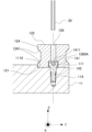
- FIG. 17 is a cross-sectional view of the adjustment hole 126 according to the third embodiment taken along a plane (YZ plane) orthogonal to the X-axis direction.
- a reference surface 1110 is provided on the mounting member 11 .
- the reference surface 1110 is a surface rising in the Z-axis direction from the mounting surface 111 and perpendicular to the Y-axis direction.
- the distance from the central axis of the adjustment screw hole 114 to the reference surface 1110 is approximately equal to the distance from the central axis of the adjustment hole 126 to the side surface 124 of the rail 12 .
- the rail 12 When fixing the rail 12 to the mounting member 11 , the rail 12 is placed on the mounting surface 111 from the upper side of the mounting surface 111 with the eccentric bolt 14 attached to the mounting member 11 .
- the eccentric bolt 14 When the eccentric bolt 14 is attached to the mounting member 11, the plane including the central axis A2 of the threaded portion 142 and the central axis A1 of the head portion 141 is perpendicular to the Y-axis direction as in the first embodiment. The angle of the head 141 of the eccentric bolt 14 is adjusted.
- the mounting bolt 13 After placing the rail 12 on the mounting surface 111 of the mounting member 11, the mounting bolt 13 is inserted into each bolt mounting hole 125 of the rail 12 and temporarily tightened. At this time, the mounting bolts 13 are temporarily tightened with a torque that allows the rails 12 to move in the Y-axis direction. Next, by inserting the tool 30 into the adjustment hole 126 and rotating the eccentric bolt 14, a pressing force is applied in the Y-axis direction to the bolt contact surface 1261A on the reference surface 1110 side. Thereby, the side surface 124 of the rail 12 is pressed against the reference surface 1110 . At this time, for example, by tightening the eccentric bolt 14 with a predetermined torque, a predetermined pressing force may be applied to the bolt contact surface 1261A. After tightening all the eccentric bolts 14, the mounting bolts 13 are finally tightened.
- FIG. 18 is a perspective view of the upper surface 122 side of the rail 12 according to the fourth embodiment
- FIG. 19 is a perspective view of the lower surface 121 side of the rail 12 according to the fourth embodiment.
- the upper surface 122 side of the rail 12 has the same shape as the upper surface 122 side of the rail 12 according to the third embodiment.
- the lower surface 121 of the rail 12 is formed with a recess 1260B recessed from the lower surface 121 of the second rail 12B toward the upper surface 122 from the front end surface 1231 to the rear end surface 1232 in the longitudinal direction (X-axis direction) of the rail 12. ing.
- the ends of the recess 1260B in the X-axis direction are open to the front end surface 1231 and the rear end surface 1232 of the rail 12 .
- the recess 1260B has a bolt contact surface 1261B which is two planes orthogonal to the Y-axis and parallel to each other, and an opening of the bolt mounting hole 125 and an opening of the adjustment hole 126 which are orthogonal to the Z-axis. and a bottom surface 1263B that is flat.
- the distance between the two bolt contact surfaces 1261B is equal to the distance between the two bolt contact surfaces 1261 in the first embodiment.
- the distance from the lower surface 121 of the rail 12 to the bottom surface 1263B is equal to the distance from the lower surface 121 of the rail 12 to the bottom surface 1263 in the first embodiment.
- a plurality of eccentric bolts 14 exert a pressing force on one bolt contact surface 1261A in the Y-axis direction, thereby moving the rail 12.
- the bending of the rail 12 as a whole can be corrected.
- the rails 12 can be pressed against the reference plane 1110 to prevent a step between the rails 12 from occurring.
- the concave portion 1260B opens to the front end surface 1231 and the rear end surface 1232, the rail 12 can be arranged while being moved in the X-axis direction with respect to the mounting surface 111.
- the tool 30 can be easily inserted into the hexagonal hole 1411, the rail 12 can be corrected more quickly.
- FIG. 20 is a diagram showing an example of a side view of the rail 12 according to the fifth embodiment.
- FIG. 21 is a diagram showing an example of the rail 12 according to the fifth embodiment when viewed from above.
- FIG. 22 is a diagram showing an example when the rail 12 according to the fifth embodiment is viewed from below.
- FIG. 23 is an example of a perspective view of the upper surface 122 side of the state in which the first rail 12A and the second rail 12B are connected according to the fifth embodiment.
- the front end surface 1231 is formed to protrude forward from the upper surface 122 side toward the lower surface 121 side. Further, the rear end surface 1232 is formed so as to protrude rearward from the lower surface 121 side toward the upper surface 122 side.
- the first rail 12A and the second rail 12B have the same shape. Except for the shape of the front end surface 1231 and the rear end surface 1232, the description is omitted because it is the same as the first to fourth embodiments.
- the recess 1260 is formed up to the end surface 123 of the rail 12, as in the first embodiment.
- the recess 1260 may be formed so as not to reach the end surface 123 of the rail 12 as in the second embodiment.
- the plurality of bolt mounting holes 125 and the plurality of adjustment holes 126 may be alternately formed in the longitudinal direction of the rail 12 .
- a recess 1260 is formed in the longitudinal direction (X-axis direction) of the rail 12 from the front end surface 1231 to the rear end surface 1232 so as to be recessed from the lower surface 121 toward the upper surface 122 of the rail 12. may have been
- FIG. 24 is a diagram showing an example of the rail 12 and the carriage 520 according to the fifth embodiment when viewed from the rear side.
- FIG. 25 is a diagram showing an example of a side view of the rail 12 and the carriage 520 according to the fifth embodiment.
- the carriage 520 includes a carriage body 521 located above the top surface 122 of the rail 12 and protruding in the Y-axis direction beyond the side surface 124 of the rail 12 .
- the carriage 520 also includes four roller shafts 522 projecting downward in the Z-axis direction from the carriage body 521 .
- Two roller shafts 522 are provided with the rail 12 interposed therebetween.
- the carriage 520 includes four rollers 523 rotatably supported on respective roller shafts 522 .
- the roller 523 has a cylindrical shape, and upper and lower edges of the roller 523 are formed with rolling surfaces 5231 parallel to the upper and lower rolling surfaces 1241 of the rail 12, respectively.
- the roller 523 rotates around the roller shaft 522 while the rolling surface 5231 is in contact with the rolling surface 1241 of the rail 12 . That is, one roller 523 is in contact with the upper and lower rolling surfaces 1241 of the rail 12 .
- the rail 12 is sandwiched between two rollers 523 provided in the Y-axis direction. Further, the rail 12 is sandwiched between the two rollers 523 in the same manner at positions separated in the X-axis direction.
- FIG. 26 is a diagram showing an example of the connection portion B2 of the rail 12 according to the fifth embodiment.
- D1 is a portion of the rolling surface 1241A on the upper surface 122 side of the rail 12 where the upper rolling surface of the roller 523 (hereinafter referred to as the upper rolling surface 5231A) contacts (hereinafter referred to as the upper contact portion D1).
- D2 is a point (hereinafter referred to as (referred to as lower contact portion D2).
- the upper contact portion D1 and the lower contact portion D2 are present at positions shifted in the Z-axis direction.
- the upper contact portion D1 is positioned on the first rail 12A
- the lower contact portion D2 is positioned on the second rail 12B.
- the connecting portion B2 is formed obliquely with respect to the traveling direction of the carriage 50 . Therefore, the upper rolling surface 5231A of the roller 523 and the lower rolling surface 5231B located thereunder do not pass through the connecting portion B2 at the same time. Therefore, even if a sound or vibration occurs when the roller 523 passes through the connection portion B2, the sound or vibration does not occur at the upper contact portion D1 and the lower contact portion D2 at the same time. Maximum value can be reduced.
- connection portion B2 passes from the upper side to the lower side of the upper rolling surface 5231A of the roller 523. Even if there is a gap in the connection portion B2, the upper rolling surface 5231A is prevented from falling into the gap. The same applies to the lower rolling surface 5231B. In this manner, vibration and noise can be reduced as compared with the case where the connection portion B2 is orthogonal to the X-axis direction.
- the rail 12 according to the fifth embodiment it is possible to obtain the same effects as those of the rails 12 according to the first to fourth embodiments while reducing vibration and noise. .
- FIG. 27 is a diagram showing an example of a side view of the rail 12 according to the sixth embodiment.
- FIG. 28 is a diagram showing an example when the rail 12 according to the sixth embodiment is viewed from above.
- FIG. 29 is a diagram showing an example when the rail 12 according to the sixth embodiment is viewed from below.
- FIG. 30 is an example of a perspective view of the upper surface 122 side of the state in which the first rail 12A and the second rail 12B are connected according to the sixth embodiment.
- the end surface 123 is perpendicular to the upper surface 122 and the lower surface 121 and is inclined with respect to the side surface 124 .
- the front end surface 1231 is formed so as to protrude forward from the left side surface 124 toward the right side surface 124 .
- the rear end surface 1232 is formed so as to protrude rearward from the right side surface 124 toward the left side surface 124 . Except for the shape of the front end surface 1231 and the rear end surface 1232, the description is omitted because it is the same as the first to fourth embodiments.
- the concave portion 1260 is formed up to the end surface 123 of the rail 12 as in the first embodiment.
- the recess 1260 may be formed so as not to reach the end surface 123 of the rail 12 as in the second embodiment.
- the rail 12 may have a plurality of bolt mounting holes 125 and a plurality of adjustment holes 126 alternately formed in the longitudinal direction of the rail.
- the lower surface 121 of the rail 12 has a plurality of grooves extending from the front end surface 1231 to the rear end surface 1232 and from the lower surface 121 to the upper surface 122 of the rail 12 in the longitudinal direction (X-axis direction) of the rail 12 .
- a recess 1260 may be formed so as to be recessed.
- the same effects as those of the rails according to the first to fourth embodiments can be obtained. Furthermore, according to the rail 12 according to the sixth embodiment, since the plurality of rollers 523 shown in FIGS. 24 and 25 do not pass through the connection portion B2 at the same time, noise and vibration can be reduced.
Landscapes
- Engineering & Computer Science (AREA)
- General Engineering & Computer Science (AREA)
- Mechanical Engineering (AREA)
- Bearings For Parts Moving Linearly (AREA)
Abstract
Description
取付面に接する第一面と、
前記第一面に対向する第二面と、
前記第一面と前記第二面との間を貫通する貫通穴と、
前記貫通穴の前記第一面側の開口であって、前記第一面から前記第二面に向かって凹むように形成される凹部と、
を有するレールを備えた案内装置であって、
前記凹部は、前記第一面に直交する面であって前記レールの幅方向に直交する第三面を含み、
前記凹部には、前記取付面と直交する基準軸に対して偏心して回転し、前記第三面に対して前記レールの幅方向に力を加える偏心部が格納され、
前記貫通穴の直径が、前記凹部の前記幅方向の長さよりも短い、
案内装置である。
まず、案内装置1の構成について説明する。図1は、本実施形態に係る案内装置1の外観を示す図である。案内装置1は、レール12と、レール12の長手方向沿いに相対移動可能に組み付けられるキャリッジ50と、を備える。レール12は、例えば工作機械等のユーザ設備の取付面に取り付けられ、キャリッジ50に当該ユーザ設備のテーブルが取り付けられる。この場合、テーブルを含む可動部の運動は、案内装置1によって案内される。なお、案内装置1を上下反転し、キャリッジ50をユーザ設備の取付面に取り付け、レール12をテーブルに取り付けることもできる。また、案内装置1は、レール12の長手方向が水平でなく、水平面に対して傾斜し或いは直交する状態で用いられてもよい。
第1実施形態では、凹部1260が第二レール12Bの前端面1231まで形成されているが、本第2実施形態では、凹部1260Aが第二レール12Bの前端面1231に達しないように形成されている。図13は、第2実施形態に係る第二レール12Bの下面121側の斜視図である。凹部1260は、Z軸方向と直交する平面により切断したときの断面が長穴になるように形成されている。Y軸方向と直交する2つの平面であって互いに平行な平面であるボルト接触面1261Aが形成されており、2つのボルト接触面1261Aの間の距離は、第1実施形態に係る2つのボルト接触面1261の間の距離と等しい。なお、凹部1260Aの前端面1231側の形状以外は、第1実施形態と同じである。したがって、2つのボルト接触面1261Aの間の距離は、調整穴126の直径よりも長い。
第3実施形態では、1本のレール12の曲がりを矯正する例について説明する。図14は、第3実施形態に係るレール12の上面122側の斜視図であり、図15は、第3実施形態に係るレール12の下面121側の斜視図である。また、図16は、第3実施形態に係るレール12を取付部材11に取り付けた状態での断面図である。
第4実施形態では、1本のレール12の曲がりを矯正する例について説明する。図18は、第4実施形態に係るレール12の上面122側の斜視図であり、図19は、第4実施形態に係るレール12の下面121側の斜視図である。
第1実施形態から第4実施形態に係るレール12は、端面123が、X軸方向と直交している。一方、第5実施形態に係るレール12は、端面123が、X軸方向に対して傾斜している。さらに、端面123は、Y軸方向と平行であり、且つ、Z軸方向に対して傾斜している。図20は、第5実施形態に係るレール12の側面視の一例を示した図である。図21は、第5実施形態に係るレール12を上方から見たときの一例を示した図である。図22は、第5実施形態に係るレール12を下方から見たときの一例を示した図である。図23は、第5実施形態に係る第一レール12Aと第二レール12Bとを接続した状態の上面122側の斜視図の一例である。
第6実施形態では、端面123が、X軸方向に対して傾斜している。さらに、端面123は、Y軸方向に対しても傾斜しており、且つ、Z軸方向と平行である。図27は、第6実施形態に係るレール12の側面視の一例を示した図である。図28は、第6実施形態に係るレール12を上方から見たときの一例を示した図である。図29は、第6実施形態に係るレール12を下方から見たときの一例を示した図である。図30は、第6実施形態に係る第一レール12Aと第二レール12Bとを接続した状態の上面122側の斜視図の一例である。
Claims (6)
- 取付面に接する第一面と、
前記第一面に対向する第二面と、
前記第一面と前記第二面との間を貫通する貫通穴と、
前記貫通穴の前記第一面側の開口であって、前記第一面から前記第二面に向かって凹むように形成される凹部と、
を有するレールを備えた案内装置であって、
前記凹部は、前記第一面に直交する面であって前記レールの幅方向に直交する第三面を含み、
前記凹部には、前記取付面と直交する基準軸に対して偏心して回転し、前記第三面に対して前記レールの幅方向に力を加える偏心部が格納され、
前記貫通穴の直径が、前記凹部の前記幅方向の長さよりも短い、
案内装置。 - 前記偏心部は、前記基準軸を中心として回転する偏心ボルトの頭部である、
請求項1に記載の案内装置。 - 前記凹部は、前記レールの少なくとも一方の端部まで形成されている、
請求項1または2に記載の案内装置。 - 前記レールを前記取付面に固定するボルトを通す穴である取付穴よりも前記レールの端部側に、前記貫通穴が形成されている、
請求項1または2に記載の案内装置。 - 前記レールを前記取付面に固定するボルトを通す穴である複数の取付穴の間に、前記貫通穴が形成されている、
請求項1または2に記載の案内装置。 - 前記レールの軸方向の端面が前記レールの軸方向に対して傾斜している、
請求項1または2に記載の案内装置。
Priority Applications (5)
| Application Number | Priority Date | Filing Date | Title |
|---|---|---|---|
| CN202280079535.5A CN118339385A (zh) | 2021-12-01 | 2022-11-28 | 引导装置 |
| KR1020247020472A KR20240112892A (ko) | 2021-12-01 | 2022-11-28 | 안내 장치 |
| EP22901230.7A EP4443014A4 (en) | 2021-12-01 | 2022-11-28 | GUIDE DEVICE |
| US18/714,412 US20250020162A1 (en) | 2021-12-01 | 2022-11-28 | Guide device |
| JP2023564955A JPWO2023100797A1 (ja) | 2021-12-01 | 2022-11-28 |
Applications Claiming Priority (2)
| Application Number | Priority Date | Filing Date | Title |
|---|---|---|---|
| JP2021-195280 | 2021-12-01 | ||
| JP2021195280 | 2021-12-01 |
Publications (1)
| Publication Number | Publication Date |
|---|---|
| WO2023100797A1 true WO2023100797A1 (ja) | 2023-06-08 |
Family
ID=86612180
Family Applications (1)
| Application Number | Title | Priority Date | Filing Date |
|---|---|---|---|
| PCT/JP2022/043741 Ceased WO2023100797A1 (ja) | 2021-12-01 | 2022-11-28 | 案内装置 |
Country Status (6)
| Country | Link |
|---|---|
| US (1) | US20250020162A1 (ja) |
| EP (1) | EP4443014A4 (ja) |
| JP (1) | JPWO2023100797A1 (ja) |
| KR (1) | KR20240112892A (ja) |
| CN (1) | CN118339385A (ja) |
| WO (1) | WO2023100797A1 (ja) |
Cited By (1)
| Publication number | Priority date | Publication date | Assignee | Title |
|---|---|---|---|---|
| WO2025061757A1 (de) * | 2023-09-18 | 2025-03-27 | Igus Gmbh | Gleitlageranordnung mit mehrteiliger schiene |
Citations (2)
| Publication number | Priority date | Publication date | Assignee | Title |
|---|---|---|---|---|
| DE2424627A1 (de) * | 1974-05-21 | 1975-12-04 | August Laepple Gmbh & Co Werkz | Vorrichtung zur schraubbefestigung von gleitfuehrungsplatten |
| JP2003127037A (ja) | 2001-10-18 | 2003-05-08 | Nsk Ltd | 直動案内装置の案内レール取付け方法及び直動案内装置ならびに直動案内装置用レール取付調整具 |
Family Cites Families (5)
| Publication number | Priority date | Publication date | Assignee | Title |
|---|---|---|---|---|
| JP4323675B2 (ja) * | 2000-03-30 | 2009-09-02 | Thk株式会社 | 減衰機能付案内装置及びこの装置を用いた免震装置 |
| JP2002005162A (ja) * | 2000-06-21 | 2002-01-09 | Thk Co Ltd | 転がり案内装置 |
| JP4116259B2 (ja) * | 2001-01-29 | 2008-07-09 | 財団法人鉄道総合技術研究所 | 固着装置及び転てつ機類据付装置 |
| DE102013108650A1 (de) * | 2013-08-09 | 2015-02-12 | Wittenstein Ag | Befestigungssystem mit Exzenter |
| EP3096029A4 (en) * | 2014-01-17 | 2017-04-19 | NSK Ltd. | Linear motion guiding device |
-
2022
- 2022-11-28 US US18/714,412 patent/US20250020162A1/en active Pending
- 2022-11-28 EP EP22901230.7A patent/EP4443014A4/en active Pending
- 2022-11-28 KR KR1020247020472A patent/KR20240112892A/ko active Pending
- 2022-11-28 WO PCT/JP2022/043741 patent/WO2023100797A1/ja not_active Ceased
- 2022-11-28 CN CN202280079535.5A patent/CN118339385A/zh active Pending
- 2022-11-28 JP JP2023564955A patent/JPWO2023100797A1/ja active Pending
Patent Citations (2)
| Publication number | Priority date | Publication date | Assignee | Title |
|---|---|---|---|---|
| DE2424627A1 (de) * | 1974-05-21 | 1975-12-04 | August Laepple Gmbh & Co Werkz | Vorrichtung zur schraubbefestigung von gleitfuehrungsplatten |
| JP2003127037A (ja) | 2001-10-18 | 2003-05-08 | Nsk Ltd | 直動案内装置の案内レール取付け方法及び直動案内装置ならびに直動案内装置用レール取付調整具 |
Non-Patent Citations (1)
| Title |
|---|
| See also references of EP4443014A4 |
Cited By (1)
| Publication number | Priority date | Publication date | Assignee | Title |
|---|---|---|---|---|
| WO2025061757A1 (de) * | 2023-09-18 | 2025-03-27 | Igus Gmbh | Gleitlageranordnung mit mehrteiliger schiene |
Also Published As
| Publication number | Publication date |
|---|---|
| CN118339385A (zh) | 2024-07-12 |
| EP4443014A4 (en) | 2025-04-02 |
| KR20240112892A (ko) | 2024-07-19 |
| JPWO2023100797A1 (ja) | 2023-06-08 |
| EP4443014A1 (en) | 2024-10-09 |
| US20250020162A1 (en) | 2025-01-16 |
Similar Documents
| Publication | Publication Date | Title |
|---|---|---|
| US5460452A (en) | Linear motion rolling guide unit | |
| DE112017002744B4 (de) | Linearer Ausfahr- und Einziehmechanismus | |
| JP3547209B2 (ja) | 直動転がり案内ユニット | |
| EP4443014A1 (en) | Guide device | |
| JP2567326Y2 (ja) | トラックレール固定構造及び該構造を具備した直動案内ユニット | |
| DE69717663T2 (de) | Roboter des cartesischen typs | |
| JPH11108056A (ja) | 有限直動形ガイドウェイ及びそれを組み込んだ有限直動案内ユニット | |
| KR101709286B1 (ko) | 멀티 클램프 | |
| JP2006080260A (ja) | ガイド機構およびワーク搬送装置 | |
| KR100679680B1 (ko) | 리니어 가이드 | |
| WO2021089153A1 (de) | Sonotrodenanordnung mit vereinfacht bedienbarem nullpunktlager für ultraschallschweisseinrichtung | |
| JP6133695B2 (ja) | 工作機械の水平調整装置 | |
| CN118632958A (zh) | 轨道的连接结构 | |
| JPH078893Y2 (ja) | 締結装置 | |
| JP4562140B2 (ja) | 繋ぎ用軌道レールを備えた直動案内ユニット | |
| JP4712662B2 (ja) | 運動案内装置及び運動案内装置の取付け方法 | |
| US7806595B2 (en) | Miniature linear motion guide unit | |
| TW202400910A (zh) | 線性導軌 | |
| US20250163968A1 (en) | Jig for assisting attachment of rail cover | |
| JPH07127638A (ja) | 位置決め機構を内蔵した直動案内装置 | |
| KR100310400B1 (ko) | 선형안내식이동유니트용지지베어링 | |
| JP2024158521A (ja) | スライドレールの製造方法 | |
| JP5797625B2 (ja) | リニアガイド装置及びリニアアクチュエータ装置 | |
| JP3173820U (ja) | クロスローラガイド | |
| JP2575926B2 (ja) | 直線案内装置 |
Legal Events
| Date | Code | Title | Description |
|---|---|---|---|
| 121 | Ep: the epo has been informed by wipo that ep was designated in this application |
Ref document number: 22901230 Country of ref document: EP Kind code of ref document: A1 |
|
| ENP | Entry into the national phase |
Ref document number: 2023564955 Country of ref document: JP Kind code of ref document: A |
|
| WWE | Wipo information: entry into national phase |
Ref document number: 18714412 Country of ref document: US |
|
| WWE | Wipo information: entry into national phase |
Ref document number: 202280079535.5 Country of ref document: CN |
|
| ENP | Entry into the national phase |
Ref document number: 20247020472 Country of ref document: KR Kind code of ref document: A |
|
| NENP | Non-entry into the national phase |
Ref country code: DE |
|
| ENP | Entry into the national phase |
Ref document number: 2022901230 Country of ref document: EP Effective date: 20240701 |