WO2023112367A1 - 情報出力方法、および、情報出力装置 - Google Patents
情報出力方法、および、情報出力装置 Download PDFInfo
- Publication number
- WO2023112367A1 WO2023112367A1 PCT/JP2022/027243 JP2022027243W WO2023112367A1 WO 2023112367 A1 WO2023112367 A1 WO 2023112367A1 JP 2022027243 W JP2022027243 W JP 2022027243W WO 2023112367 A1 WO2023112367 A1 WO 2023112367A1
- Authority
- WO
- WIPO (PCT)
- Prior art keywords
- information
- return
- moving body
- travel route
- area
- Prior art date
- Legal status (The legal status is an assumption and is not a legal conclusion. Google has not performed a legal analysis and makes no representation as to the accuracy of the status listed.)
- Ceased
Links
Images









Classifications
-
- G—PHYSICS
- G05—CONTROLLING; REGULATING
- G05D—SYSTEMS FOR CONTROLLING OR REGULATING NON-ELECTRIC VARIABLES
- G05D1/00—Control of position, course, altitude or attitude of land, water, air or space vehicles, e.g. using automatic pilots
- G05D1/20—Control system inputs
- G05D1/22—Command input arrangements
- G05D1/221—Remote-control arrangements
- G05D1/225—Remote-control arrangements operated by off-board computers
-
- B—PERFORMING OPERATIONS; TRANSPORTING
- B60—VEHICLES IN GENERAL
- B60W—CONJOINT CONTROL OF VEHICLE SUB-UNITS OF DIFFERENT TYPE OR DIFFERENT FUNCTION; CONTROL SYSTEMS SPECIALLY ADAPTED FOR HYBRID VEHICLES; ROAD VEHICLE DRIVE CONTROL SYSTEMS FOR PURPOSES NOT RELATED TO THE CONTROL OF A PARTICULAR SUB-UNIT
- B60W60/00—Drive control systems specially adapted for autonomous road vehicles
- B60W60/001—Planning or execution of driving tasks
-
- G—PHYSICS
- G01—MEASURING; TESTING
- G01C—MEASURING DISTANCES, LEVELS OR BEARINGS; SURVEYING; NAVIGATION; GYROSCOPIC INSTRUMENTS; PHOTOGRAMMETRY OR VIDEOGRAMMETRY
- G01C21/00—Navigation; Navigational instruments not provided for in groups G01C1/00 - G01C19/00
- G01C21/26—Navigation; Navigational instruments not provided for in groups G01C1/00 - G01C19/00 specially adapted for navigation in a road network
- G01C21/34—Route searching; Route guidance
- G01C21/3407—Route searching; Route guidance specially adapted for specific applications
- G01C21/3415—Dynamic re-routing, e.g. recalculating the route when the user deviates from calculated route or after detecting real-time traffic data or accidents
-
- G—PHYSICS
- G01—MEASURING; TESTING
- G01C—MEASURING DISTANCES, LEVELS OR BEARINGS; SURVEYING; NAVIGATION; GYROSCOPIC INSTRUMENTS; PHOTOGRAMMETRY OR VIDEOGRAMMETRY
- G01C21/00—Navigation; Navigational instruments not provided for in groups G01C1/00 - G01C19/00
- G01C21/26—Navigation; Navigational instruments not provided for in groups G01C1/00 - G01C19/00 specially adapted for navigation in a road network
- G01C21/34—Route searching; Route guidance
- G01C21/3453—Special cost functions, i.e. other than distance or default speed limit of road segments
- G01C21/3461—Preferred or disfavoured areas, e.g. dangerous zones, toll or emission zones, intersections, manoeuvre types or segments such as motorways, toll roads or ferries
-
- G—PHYSICS
- G08—SIGNALLING
- G08G—TRAFFIC CONTROL SYSTEMS
- G08G1/00—Traffic control systems for road vehicles
- G08G1/09—Arrangements for giving variable traffic instructions
-
- G—PHYSICS
- G08—SIGNALLING
- G08G—TRAFFIC CONTROL SYSTEMS
- G08G1/00—Traffic control systems for road vehicles
- G08G1/16—Anti-collision systems
-
- B—PERFORMING OPERATIONS; TRANSPORTING
- B60—VEHICLES IN GENERAL
- B60W—CONJOINT CONTROL OF VEHICLE SUB-UNITS OF DIFFERENT TYPE OR DIFFERENT FUNCTION; CONTROL SYSTEMS SPECIALLY ADAPTED FOR HYBRID VEHICLES; ROAD VEHICLE DRIVE CONTROL SYSTEMS FOR PURPOSES NOT RELATED TO THE CONTROL OF A PARTICULAR SUB-UNIT
- B60W2554/00—Input parameters relating to objects
- B60W2554/40—Dynamic objects, e.g. animals, windblown objects
- B60W2554/406—Traffic density
-
- B—PERFORMING OPERATIONS; TRANSPORTING
- B60—VEHICLES IN GENERAL
- B60W—CONJOINT CONTROL OF VEHICLE SUB-UNITS OF DIFFERENT TYPE OR DIFFERENT FUNCTION; CONTROL SYSTEMS SPECIALLY ADAPTED FOR HYBRID VEHICLES; ROAD VEHICLE DRIVE CONTROL SYSTEMS FOR PURPOSES NOT RELATED TO THE CONTROL OF A PARTICULAR SUB-UNIT
- B60W2555/00—Input parameters relating to exterior conditions, not covered by groups B60W2552/00, B60W2554/00
- B60W2555/60—Traffic rules, e.g. speed limits or right of way
-
- B—PERFORMING OPERATIONS; TRANSPORTING
- B60—VEHICLES IN GENERAL
- B60W—CONJOINT CONTROL OF VEHICLE SUB-UNITS OF DIFFERENT TYPE OR DIFFERENT FUNCTION; CONTROL SYSTEMS SPECIALLY ADAPTED FOR HYBRID VEHICLES; ROAD VEHICLE DRIVE CONTROL SYSTEMS FOR PURPOSES NOT RELATED TO THE CONTROL OF A PARTICULAR SUB-UNIT
- B60W2556/00—Input parameters relating to data
- B60W2556/45—External transmission of data to or from the vehicle
Definitions
- the present disclosure relates to an information output method and an information output device.
- Patent Document 1 technologies related to mobile objects such as vehicles that operate automatically have been developing.
- Patent document 1 discloses situation detection means for detecting the surrounding situation in front of the road on which the vehicle travels, and stop place determination means for determining the stop place of the vehicle based on the detection result obtained by the situation detection means.
- An apparatus comprising the is disclosed.
- the present disclosure provides an information output method and the like that allows a mobile object to travel efficiently.
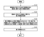
- An information output method is an information output method in an information output device, in which first information about an area including a travel route along which a moving body travels is obtained, and second information about an object present in the area is obtained. Obtaining information, and based on at least one of the first information and the second information, third information regarding return of the moving body to the travel route from one or more points at which the moving body may stop in the area. and outputs the third information.
- an information output method and the like capable of efficiently running a moving body are provided.
- FIG. 1 is a block diagram showing the configuration of an information output system according to an embodiment.
- FIG. 2 is a diagram showing a first example of road information according to the embodiment.
- FIG. 3 is a diagram showing object information according to the embodiment.
- FIG. 4 is a diagram schematically showing traveling of a moving body in a target area according to the embodiment.
- FIG. 5 is a diagram for explaining a plurality of individual regions in the target region according to the embodiment;
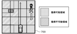
- FIG. 6 is a diagram for explaining a restorable area and an unrestorable area according to the embodiment.
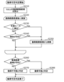
- 7 is a flowchart illustrating a first example of a processing procedure of the determination device according to the embodiment;
- FIG. 1 is a block diagram showing the configuration of an information output system according to an embodiment.
- FIG. 2 is a diagram showing a first example of road information according to the embodiment.
- FIG. 3 is a diagram showing object information according to the embodiment.
- FIG. 4 is a diagram schematically showing traveling of a moving body in
- FIG. 7A is a flowchart illustrating another example of the first example of the processing procedure of the determination device according to the embodiment;
- FIG. FIG. 8 is a flowchart of a procedure for determining whether or not recovery is possible by the determination device according to the embodiment.
- FIG. 9 is a diagram showing a second example of road information according to the embodiment.
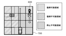
- FIG. 10 is a diagram for explaining a non-stoppable area according to the embodiment.
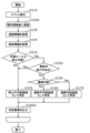
- FIG. 11 is a flowchart illustrating a second example of processing procedures of the determination device according to the embodiment.
- FIG. 12 is a flow chart showing a processing procedure of rule propriety judgment of the judging device according to the embodiment.
- FIG. 13 is a flow chart showing a processing procedure of interference presence/absence determination of the determination device according to the embodiment.
- FIG. 14 is a diagram showing a third example of road information according to the embodiment.
- 15 is a diagram illustrating an example of recovery time information displayed on the output device according to the embodiment;
- FIG. 15A is a diagram showing another example of recovery time information displayed on the output device according to the embodiment;
- FIG. 15B is a diagram illustrating another example of recovery time information displayed on the output device according to the embodiment;
- FIG. 16 is a diagram illustrating another example of recovery time information displayed on the output device according to the embodiment;
- FIG. 16A is a diagram illustrating another example of return time information displayed on the output device according to the embodiment;
- FIG. 17 is a flowchart illustrating a third example of a processing procedure of the determination device according to the embodiment;
- FIG. FIG. 18 is a flowchart illustrating a modification of the procedure for determining whether or not recovery is possible by the determination device according to the embodiment.
- FIG. 19 is a flow chart showing the processing procedure of the information output device according to the embodiment.
- the mobile body In the operation of an automatically operated mobile body, for example, the mobile body is caused to travel along a predetermined travel route to a destination.
- the mobile body When the mobile body is automatically driven so as to travel along a predetermined travel route, there are cases where the mobile body cannot be automatically driven due to changes in weather, traffic conditions, or the like. In such a case, it may be necessary to manually withdraw the moving body from a predetermined travel route and stop it by remote control or the like. In such a case, unless the moving body is evacuated to an appropriate place, it may not be possible to return the moving body to the predetermined travel route by automatic operation.
- the moving body is manually returned to the predetermined travel route by remote control, etc., or in some cases, the worker gets into the moving body and drives the moving body to return to the predetermined travel route. need to let As described above, if the moving body is not stopped at an appropriate position, the efficiency of driving the moving body to the destination decreases.
- Patent Document 1 refers to safely stopping the moving body, it is necessary to efficiently run the moving body when the moving body is restarted after being stopped. There is no disclosure of a technique, for example, a technique for efficiently returning a moving object to a predetermined travel route.
- an information output method is an information output method in an information output device, in which first information about an area including a travel route along which a moving body travels is acquired, and information about an object existing in the area is obtained. Second information is obtained, and based on at least one of the first information and the second information, a second information relating to return of the moving body to the travel route from one or more points at which the moving body can stop in the area; 3 information is generated and the third information is output.
- information regarding the return to the originally traveled route is output.
- information indicating the route for returning (return route)
- information indicating the time required for the return e.g., information indicating the time required for the return
- information indicating the time required for the return e.g., information indicating the time required for the return
- information indicating the time required for the return e.g., information indicating the time required for the return
- information indicating whether or not there is, or information indicating whether or not recovery is possible by automatic operation when the mobile object can be automatically operated is output. Therefore, for example, by presenting the above-described information to the user who drives and stops the mobile object by an output device such as a display, the user can find a point with a short return route or a short return time.
- the point at which the moving body can be efficiently returned can be grasped. Therefore, according to the information output method according to one aspect of the present disclosure, it is possible to appropriately select a point at which the moving object can be efficiently returned to the travel route, so that the moving object can travel efficiently.
- the third information it is determined whether or not the moving body can return to the travel route from the one or more points based on at least one of the first information and the second information. and generating the third information including return propriety information indicating whether or not the moving body can return to the travel route from the one or more points.
- the moving object can be driven automatically
- the travel route is a route on which the moving object can travel automatically
- the generation of the third information includes: Determining whether or not it is possible to return to the travel route from one or more points, and determining whether or not the moving body can return to the travel route from the one or more points by automatic operation. generating the third information including
- the moving body can be appropriately stopped at a point where automatic operation can return to the travel route.
- a return route along which the moving object returns to the traveling route from the one or more points is calculated, and the first information and the second information are calculated. Based on at least one of, it is determined whether or not the moving body can travel the return route and reach the traveling route, and if it is determined that the traveling route can be reached, the moving body is at the one or more points If it is determined that it is possible to return to the travel route from the moving object, and if it is determined that the travel route cannot be reached, it is determined that the moving object cannot return to the travel route.
- the moving body in the generation of the third information, it is determined whether or not the moving body needs to retreat until the moving body returns to the travel route from the one or more points. determines whether or not the moving object can return to the travel route from the one or more points, based on the result of determination as to whether or not it is necessary to move backward.
- a high level of driving skill is required to reverse the moving object.
- a higher level of driving skill is required than when driving a mobile body. Therefore, it is possible to return the moving object to the traveling route regardless of the driving skill of the user who drives the moving object by determining that the point at which the moving object needs to be reversed in order to return to the traveling route cannot be returned. You can choose the location where you can.
- the moving body can return to the travel route from the one or more points, and that the moving body needs to retreat. If determined, a retreat distance by which the moving body retreats from the one or more points until it returns to the travel route is calculated, and if the retreat distance is equal to or greater than a predetermined distance, the moving body travels from the one or more points It is determined that it is impossible to return to the travel route from the point, and if the retreat distance is less than the predetermined distance, it is determined that the moving object can return to the travel route from the one or more points.
- a high level of driving skill is required to reverse the moving object.
- the longer the moving body is moved backward the higher the driving skill required. Therefore, by determining that the point where the moving object needs to retreat a long distance in order to return to the traveling route cannot be returned, the moving object can be returned to the traveling route regardless of the driving skill of the user who drives the moving object. can be appropriately selected.
- the third information based on at least one of the first information and the second information, it is determined whether or not the moving object can stop at the one or more points.
- the third information including stop permission/prohibition information indicating whether or not is generated.
- the return time required for the moving body to return to the travel route from the one or more points is calculated, and the third information includes return time information indicating the return time.
- the third information including the shortest point information indicating the point that takes the shortest time to return to the travel route among the one or more points is generated.
- the shortest point information is presented to the user who drives and stops the moving body by an output device having a display or the like, so that the point where the moving body can return to the travel route in the most time efficient manner can be determined. It can be made easier for the user to understand.
- the third information is generated based on at least one of the first information and the second information, and performance information indicating the running performance of the moving body.
- the route that can be traveled may differ depending on the driving performance, such as whether a small turn is effective or not. Therefore, according to this, for example, it is possible to more appropriately select a point at which the moving object can be returned to the travel route.
- the third information is generated based on at least one of the first information and the second information, and traffic information indicating the traffic volume in the area.
- the first information includes rule information indicating traffic rules in the area, travel permission/prohibition information indicating whether or not the moving object can travel in the area, and distance from the area to the travel route. including at least one of the indicated distance information.
- the second information indicates whether or not the object exists in the area detected by the sensor unit arranged on the moving object.
- the one or more points include the point where the moving object is located.
- the generation of the third information among the one or more points, points at which the travel route can be returned are indicated in the first color, and points at which the travel route cannot be returned are indicated in the first color. generates said third information including image information shown in a different second color.
- the image information is presented to the user who drives and stops the moving body by an output device having a display or the like, so that the user can be notified of points at which the moving body can and cannot be returned to the traveling route. It can be intuitively understood.
- the mobile body operates at least by remote control by a terminal connected via a network, and outputs the third information to the terminal when outputting the third information.
- Remote operation is more difficult to operate than riding a mobile object and driving it, and it may be difficult to drive on narrow roads. Therefore, for example, when the moving body is traveling by remote control, information on whether or not it is possible to return to the traveling route is output as information on returning to the traveling route.
- the moving body can be stopped at a point where the moving body can be returned to the travel route.
- an information output device includes a first acquisition unit that acquires first information regarding an area including a travel route along which a moving object travels, and acquires second information regarding an object that exists in the area. a second acquisition unit; and a third acquisition unit relating to return of the moving object to the travel route from one or more points where the moving object may stop in the area, based on at least one of the first information and the second information.
- a generation unit that generates information and an output unit that outputs the third information.
- non-transitory recording media such as systems, methods, integrated circuits, computer programs, or computer-readable CD-ROMs. Any combination of circuits, computer programs, or non-transitory recording media may be used.
- FIG. 1 is a block diagram showing the configuration of an information output system 500 according to the embodiment.
- the information output system 500 When the mobile body 300 stops at a point (area) while the mobile body is traveling along a predetermined travel route, the information output system 500 returns to the travel route from the point (that is, returns).
- information on the road on which the mobile object 300 travels and its surrounding area also called road information
- sensing results of objects such as obstacles located around the mobile object 300
- object information It is a system that generates and presents to the user based on the Specifically, the information output system 500 determines whether or not a predetermined area is an area in which it is possible to return to the travel route based on the road information and the object information, and presents the determination result.
- the moving body 300 travels along a predetermined travel route toward the destination.
- the information output system 500 outputs information about return to the moving object 300 so that it can return to the travel route from the point where it was paused (that is, return) and/or to facilitate the return.
- the mobile object 300 can operate automatically, and the travel route is a route on which the mobile object 300 can travel automatically.
- the moving body 300 is, for example, at a level at which automatic operation is possible without the driver's operation (for example, the automatic driving level is level 3), and includes automatic driving (a state in which the moving body 300 controls the operation) and manual driving (a state in which the driver controls the operation). state to control the operation) can be switched.
- the automatic driving level set for the moving body 300 may be any level.
- the information output system 500 includes a determination device 100 , a storage device 200 , a moving body 300 and an output device 400 .
- the determination device 100 is a device that determines a point where the mobile object 300 can return to the travel route based on road information and/or object information. Note that the determination device 100 is an example of an information output device.
- “recoverable” means, for example, being able to return to the travel route within a predetermined travel distance and/or within a predetermined time, being able to return to the travel route by remote control by the user, and/or automatically returning to the travel route. It means that a predetermined condition such as being able to do something is satisfied. For example, a return route candidate is calculated based on these predetermined conditions, and whether it is possible to return to the travel route by traveling along the calculated return route candidate without contacting traffic rules and objects such as pedestrians. No is determined. For example, when it is impossible to return to the travel route by remote control by the user and unable to return to the travel route by automatic operation, and the worker can return to the travel route by getting into the moving body 300 and driving it. , is unrecoverable.
- the determination device 100 includes, for example, a storage device 200 included in the information output system 500, a communication interface for communicating with the mobile object 300, and the output device 400, a nonvolatile memory storing a program, and a temporary memory for executing the program. It is realized by a computer including a volatile memory as a general storage area, an input/output port for sending and receiving signals, a processor for executing programs, and the like.
- the determination device 100 includes an acquisition unit 110 , a determination unit 120 , a generation unit 130 and an output unit 140 .
- the acquisition unit 110 is a processing unit that acquires various types of information such as road information and object information.
- the acquisition unit 110 includes a first acquisition unit 111 and a second acquisition unit 112 .
- the first acquisition unit 111 is a processing unit that acquires road information related to an area (hereinafter also referred to as a target area) that includes the travel route on which the mobile object 300 travels. Note that the road information is an example of the first information.
- the road information includes, for example, rule information indicating traffic rules in the target area, travel permission/prohibition information indicating whether or not the mobile object 300 can travel in the target area, and distance information indicating the distance from the target area to the travel route. including any Specifically, the road information includes, for example, at least one of these pieces of information in each of a plurality of areas (also called individual areas) included in the target area.
- the road information is stored in advance in the road information database 210 stored in the storage device 200, for example.
- FIG. 2 is a diagram showing a first example of road information according to the embodiment.
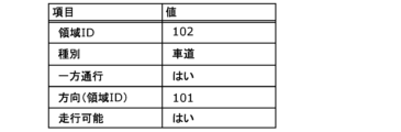
- the road information includes area ID information for identifying a plurality of individual areas included in the target area, type information indicating the type of the individual areas, and traffic rules for the individual areas. and travel permission/prohibition information indicating whether or not the moving object 300 can travel in the individual area.
- the individual area with an area ID of 102 is a roadway type, is a one-way street in the direction toward the individual area with an area ID of 101, and is travelable.
- such road information is stored in the road information database 210 for each of a plurality of individual areas.
- the mobile object 300 is provided with a GPS (Global Positioning System) receiver for acquiring the position information of the mobile object 300, and the acquisition unit 110 acquires the position information from the GPS receiver, for example. and acquiring road information of a plurality of individual areas included in the target area according to the acquired position information.
- GPS Global Positioning System
- the second acquisition unit 112 is a processing unit that acquires object information related to objects existing in the area. Specifically, the second acquisition unit 112 acquires object information regarding an object existing in the target area, which is detected based on information from the sensor unit 310 included in the moving body 300 . That is, the second acquisition unit 112 determines the presence or absence of an object, the type of the object, etc. based on the detection result of the sensor unit 310 arranged on the moving body 300, and acquires the determination result as object information.
- the object information is an example of the second information.
- the object may be arbitrarily determined in advance, such as a pedestrian, a moving body different from the moving body 300, a utility pole, or a sign.
- the object information includes, for example, information indicating whether or not an object exists in the target area detected by the sensor unit 310 arranged on the moving body 300 .
- the object information includes, for example, information indicating whether or not an object exists in each of the plurality of individual regions.
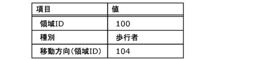
- FIG. 3 is a diagram showing object information according to the embodiment.
- the object information includes area ID information for identifying a plurality of individual areas included in the target area, type information indicating the type of the object, and object information indicating the moving direction of the object. route information;
- the object information indicates that an object of type pedestrian exists in the individual area with an area ID of 101, and that the pedestrian is heading toward the individual area with an area ID of 104. to indicate that you are moving.
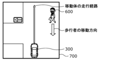
- FIG. 4 is a diagram schematically showing traveling of the moving object 300 in the target area 700 according to the embodiment.
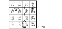
- FIG. 5 is a diagram for explaining a plurality of individual regions in target region 700 according to the embodiment.
- the target area 700 is divided into a plurality of individual areas (area IDs: 93 to 108).
- the road information includes information such as the example shown in FIG. 2
- the object information includes information such as the example shown in FIG.
- the determination unit 120 determines (calculates) the return of the moving body 300 to the travel route from one or more individual areas (also referred to as points) where the moving body 300 can stop in the target area. ).
- the generation unit 130 Based on at least one of the road information and the object information, the generation unit 130 generates return information regarding the return of the moving object 300 to the travel route from one or more individual areas (also referred to as points) where the moving object 300 may stop in the target area. This is the processing unit that generates. That is, the generation unit 130 generates return information based on the determination result of the determination unit 120 . Note that the return information is an example of the third information.
- the return information includes, for example, return possibility information indicating whether or not the moving body 300 can return to the travel route from the individual area, and return information indicating the return time required for the moving body 300 to return to the travel route from the individual area. It is time information and/or shortest point information indicating a point that takes the shortest time to return to the travel route among a plurality of individual areas.
- the determination unit 120 performs determination for each individual area, and the generation unit 130 generates restoration information for each area.
- the return information may include stop propriety information indicating whether or not the moving object 300 can stop in the individual region for each individual region.
- the individual areas may be arbitrarily defined.
- the individual regions determined by the determination unit 120 include the individual region where the moving object 300 is located.
- the generation unit 130 generates, as the return information, image information indicating characters, figures, etc. indicating the content of the return information.
- the determination unit 120 includes a rule determination unit 121, a disturbance determination unit 122, and a return determination unit 123.
- the rule determination unit 121 is a processing unit that determines whether or not the moving object 300 can stop in an individual area based on road information.
- the road information includes, for example, rule information indicating traffic rules such as the one-way traffic rules described above.
- the rule determination unit 121 determines whether or not the moving body 300 can stop in the individual area, for example, based on rule information. Specifically, the rule determination unit 121 determines whether or not the area is an area in which the vehicle can be stopped safely according to traffic rules.
- the interference determination unit 122 is a processing unit that determines whether or not the moving body 300 can stop in the individual area based on the object information.
- the object information includes, for example, information indicating the presence/absence of an object for each individual area, and object track information indicating the moving direction of the object when the object exists.
- the disturbance determination unit 122 determines, for example, based on these pieces of information, whether or not the moving object 300 can stop in the individual area. Specifically, the obstruction determination unit 122 determines whether or not the area obstructs the passage of other mobile objects (cars, bicycles, motorcycles, pedestrians, etc.).
- the determination unit 120 determines whether or not the moving object 300 can stop in the individual area based on at least one of road information (more specifically, rule information) and object information. .
- the generation unit 130 generates, for example, return information including stop permission/inhibition information indicating whether the stop is possible or not, indicating the determination result of the determination unit 120 .
- the return determination unit 123 is a processing unit that determines, based on at least one of the road information and the object information, the return of the moving object 300 to the travel route from one or more individual areas in which the moving object 300 can stop in the target area. be.
- the return determination unit 123 determines whether or not the moving body 300 can return to the travel route from one or more individual areas based on at least one of the road information and the object information. Specifically, for example, the return determination unit 123 calculates a return route for the moving body 300 to return to the traveling route from one or more individual areas based on the road information, and based on at least one of the road information and the object information, the moving body It is determined whether the vehicle 300 can travel the return route and reach the travel route. Further, when determining that the moving object 300 can reach the traveling route, the return determining unit 123 determines that the moving object 300 can return to the traveling route from one or more individual regions. It is determined that the body 300 cannot return to the travel route.
- the generation unit 130 generates return information including return availability information indicating whether or not the moving body 300 can return to the travel route from one or more individual areas.
- the generating unit 130 indicates, as the return information (more specifically, the information on whether or not to return), an area (recoverable area) that can be returned to the travel route among the one or more individual areas in the first color, and Information is generated that includes image information indicating an area that cannot be returned to the path (unrecoverable area) in a second color different from the first color.
- first color and the second color may be different colors, and arbitrary colors may be adopted.
- the entire individual region may be shown in a first color or a second color.
- only the frames (lines) forming the individual regions may be indicated in the first color or the second color.
- neither the recoverable region nor the non-recoverable region may be colored within the frame (the area surrounded by the frame), or as shown in FIG.
- both the recoverable area and the non-recoverable area may be given the same color so that the schematic diagram is displayed.
- the return determination unit 123 determines whether or not the moving object 300 can return to the traveling route from one or more individual regions by automatic operation, and determines whether the moving object 300 can return to the traveling route from one or more individual regions by automatic operation. It is also possible to generate recovery information including recovery permission/prohibition information indicating whether recovery is possible or not.
- FIG. 6 is a diagram for explaining restorable areas and non-restorable areas according to the embodiment.
- the generation unit 130 generates image information in which the restorable area and the unrestorable area are color-coded (different hatching is added in FIG. 6) to a schematic diagram or the like showing the target area 700, for example. Generate as return information.
- the image information generated by the generation unit 130 is presented, for example, to the presentation unit 410 included in the output device 400 .
- the output unit 140 is a processing unit that outputs recovery information. Specifically, the output unit 140 outputs the return information to the output device 400 .
- processing units such as the acquisition unit 110, the determination unit 120, the generation unit 130, and the output unit 140 are realized, for example, by a memory that stores control programs and a processor that executes the control programs.
- the function of each processing unit is realized, for example, by the processor executing a control program stored in the memory.
- the generation unit 130 may generate the return information based on not only the road information and the object information, but also other information.
- the generation unit 130 generates the return information based on at least one of the road information and the object information and performance information indicating the running performance of the moving object 300 .
- the performance information may be stored in the storage device 200 and acquired from the storage device 200, or may be stored in a storage unit such as a storage (not shown) provided in the mobile object 300 and acquired from the storage unit, It may be stored in a storage unit such as a storage (not shown) provided in the determination device 100 and acquired from the storage unit.
- the generation unit 130 generates return information based on at least one of the road information and the object information, and traffic information indicating the traffic volume in the target area.
- the traffic information is acquired from an external device such as a server device or VICS (registered trademark) (Vehicle Information and Communication System), for example, via a communication interface (not shown) included in the determination device 100 .
- the storage device 200 is a storage device that stores various types of information used in the processing executed by the determination device 100 .
- the storage device 200 is, for example, a storage such as an HDD (Hard Disk Drive) or flash memory.
- the storage device 200 stores a road information database 210 .
- the road information database 210 is information about the roads on which the mobile object 300 travels and the surrounding areas.
- the road information database 210 includes the road information described above for various areas, for example, the road information described above for each individual area.
- the storage device 200 may be a computer such as a server having storage in which the road information database 210 is stored.
- the storage device 200 has, for example, a communication interface for communicating with the determination device 100 .
- the storage device 200 may be connected to the determination device 100 so as to be able to communicate wirelessly, or may be connected so as to be able to communicate by wire.
- the storage device 200 when the storage device 200 is connected to the determination device 100 for wired communication, the storage device 200 includes a connector or the like to which a communication line connected to the determination device 100 is connected as a communication interface.
- the storage device 200 includes a wireless communication circuit or the like as a communication interface.
- the moving object 300 is a vehicle such as a motorcycle or an automobile.
- the moving body 300 is automatically driven along a predetermined travel route, and when it leaves the travel route and stops, the user (operator) who operates the output device 400 It is a vehicle that is remotely operated by In other words, in the present embodiment, mobile object 300 operates at least by remote control by output device 400 connected via a network.
- the mobile body 300 includes a sensor section 310 and a mobile body control section 320 .
- the sensor unit 310 is a sensor for detecting objects located around the moving body 300 .
- the sensor unit 310 includes, for example, an imaging device that captures an image of the surroundings of the mobile object 300, a distance sensor that measures the position of an object positioned around the mobile object 300, and the distance between the object and the mobile object 300.
- the second acquisition unit 112 acquires the imaging result of the imaging device from the sensor unit 310 and performs image analysis or the like to identify the type of the object or determine the position and traveling direction of the object. , the identification result and determination result are obtained as object information. Note that these processes may be performed by the sensor unit 310 . In this case, the second acquisition unit 112 acquires object information from the sensor unit 310 .
- the moving body control unit 320 is a processing unit that controls the sensor unit 310 provided in the moving body 300 and the drive mechanism such as the engine and steering for the moving body 300 to travel by automatic operation.
- the mobile body control unit 320 is implemented, for example, by an ECU (Electronic Control Unit) that includes a memory storing a control program and a processor that executes the control program.
- ECU Electronic Control Unit
- the mobile object 300 includes a communication interface such as a wireless communication circuit for communicating with the determination device 100 and the output device 400, for example.
- the output device 400 is a computer system that presents the determination results of the determination device 100 to the user, receives user operations, and operates based on the received operations. Note that the output device 400 is an example of a terminal.
- the output device 400 may be, for example, a portable computer such as a smartphone or a tablet terminal that is used by the user and that includes a touch panel display, or a personal computer that includes an operation device such as a display, a mouse, and a keyboard. It may be a stationary computer such as a computer.
- the computer includes, for example, a communication interface for communicating with the determination device 100 and the mobile object 300, a nonvolatile memory storing a program, a volatile memory serving as a temporary storage area for executing the program, and transmitting and receiving signals. and a processor for executing programs.
- the output device 400 includes a presentation unit 410 , an operation unit 420 and an output device control unit 430 .
- the presentation unit 410 is a presentation device that presents the result of determination by the determination device 100 (that is, return information) to the user.
- the presentation unit 410 is, for example, a display, and presents return information to the user by displaying an image.
- the presentation unit 410 superimposes information regarding each individual area, such as information indicating whether or not it is possible to return to information such as a map indicating the target area 700 .
- the presentation unit 410 may display the determination result of the determination device 100 in AR (Augmented Reality).
- the presentation unit 410 may present the return information to the user by voice or the like.
- the presentation unit 410 includes, for example, audio equipment such as an amplifier and a speaker.
- the operation unit 420 is an operation device that receives operations from the user.
- the operation unit 420 includes, for example, a touch panel, keyboard, and/or mouse.
- mobile object 300 operates by remote control by at least output device 400 connected via a network.
- the output device 400 for example, receives a user's operation through the operation unit 420 and transmits the received result to the moving object 300 .
- the moving body 300 operates by remote control by the user.
- the operation unit 420 may include a handle or the like to facilitate remote operation of the moving body 300 .
- the output device control unit 430 is a processing unit that controls various devices included in the output device 400 such as the presentation unit 410 and the operation unit 420 .
- the output device control unit 430 is implemented by, for example, a memory storing a control program and a processor executing the control program.
- the determination device 100, the storage device 200, and the output device 400 may be arranged inside the mobile object 300 (for example, inside a vehicle body portion included in the mobile object 300), or may be arranged outside the mobile object 300. may be placed.
- the determination device 100 determines whether or not each individual area is an area in which it is possible to return to the travel route when the moving object 300 is stopped, and generates and outputs return information including the determination result. .
- FIG. 7 is a flow chart showing a first example of the processing procedure of the determination device 100 according to the embodiment.
- the determination device 100 acquires information indicating weather and information indicating traffic volume from an external device such as a server device, and based on the acquired information, determines whether an event requiring the moving body 300 to stop has occurred. judge.
- the determination device 100 performs steps S130 to S180, which will be described later, for each individual region (S120). For example, the determination device 100 acquires the position information of the mobile object 300 from a GPS receiver or the like, determines a region to be determined based on the position information, and performs step S130 to step S130 for one or more individual regions included in the determined region. The process of S180 is performed.
- the first acquisition unit 111 acquires the road information of the individual area from the storage device 200 (S130).
- the second acquisition unit 112 acquires the object information of the individual area from the moving object 300 (more specifically, the sensor unit 310) (S140).
- the return determination unit 123 determines whether it is possible to return to the travel route from the individual area based on the road information and the object information (S150).
- the recovery determining unit 123 determines that recovery is not possible (No in S150), it determines that the individual area is an unrecoverable area (S160).
- the recovery determination unit 123 determines that recovery is possible (Yes in S150), it determines that the individual area is a recovery possible area (S170).
- the output unit 140 outputs the determination result of the restoration determination unit 123 to the output device 400 (S180). Specifically, generation section 130 generates return information indicating the determination result of return determination section 123 , and output section 140 outputs the return information generated by generation section 130 to output device 400 . Thereby, the return information is presented to the user by the presentation unit 410 .
- the determination device 100 collectively acquires road information and object information for a plurality of areas based on the position information of the moving body 300, and performs the processes of steps S150 to S170 without performing steps S130 and S140. may be performed for each individual region.
- the determination device 100 may perform the processing of steps S130 to S170 for each individual region, and then collectively output the determination results for each individual region in step S180.
- FIG. 7A is a flowchart showing another example of the first example of the processing procedure of the determination device 100 according to the embodiment.
- the flowchart shown in FIG. 7A differs from the flowchart shown in FIG. 7 in the repeated processing of step S1000.
- the determination device 100 repeatedly executes the process of step S120, in which the processes of steps S130 to S180 are repeatedly executed, until the remote operation by the user ends (S1000).
- the determination device 100 repeatedly performs the calculation of the recoverable region and the non-recoverable region (determination of each region and output of the determination result) every time the situation around the moving body 300 changes (that is, real-time update).
- FIG. 8 is a flow chart showing a processing procedure for determining whether or not recovery is possible by the determination device 100 according to the embodiment. Specifically, FIG. 8 is a flow chart showing the details of step S150 executed by the recovery determination unit 123. As shown in FIG.
- the return determination unit 123 calculates one or more return route candidates (return route candidates), which are the travel routes of the moving body 300 when returning to the travel route from the individual area (S210). For example, the return determination unit 123 calculates one or more return routes that satisfy return conditions such as being able to return to the travel route within a predetermined travel distance and/or within a predetermined time.
- the return condition is not limited to the above, and may be arbitrarily determined such as traveling on a road.
- the return determination unit 123 performs the processing of steps S230 to S250, which will be described later, for each calculated return route candidate (S220).
- the return determination unit 123 determines, based on the road information (for example, the rule information described above), whether or not the moving object 300 traveling along the return route candidate violates traffic rules (S230). For example, the return determination unit 123 determines that the traffic rule is violated when the moving body 300 runs in the reverse direction on a one-way road when traveling along the return route candidate.
- the return determination unit 123 determines whether an object exists on the return route candidate based on the object information. judge.
- the return determination unit 123 determines that the moving object 300 running on the return route candidate violates the traffic rules (Yes in S230), or determines that an object exists on the return route candidate (Yes in S240). ), and delete the return route candidate (S250).
- the return determination unit 123 appropriately deletes one or more calculated return route candidates by performing steps S230 to S250 for each return route candidate.
- the return determination unit 123 determines whether or not there is a return route candidate (S260). That is, the return determination unit 123 determines whether or not one or more return route candidates calculated in step S210 remain without being deleted.
- the recovery determination unit 123 determines No in step S150.
- the return determination unit 123 determines that there is a return route candidate (Yes in S260), it determines that it is possible to return to the travel route from the individual area (S280). That is, in this case, the recovery determination unit 123 determines Yes in step S150.
- the return determination unit 123 may proceed to the process of step S260 without executing steps S220 to S250 if even one return route candidate that satisfies the above-described return condition cannot be calculated in step S210.
- the determination device 100 determines whether or not the moving object 300 can stop for each individual area, and if the individual area determined to be able to stop causes the moving object 300 to stop, the moving object 300 travels. It determines whether or not it is an area where it is possible to return to the route, and generates and outputs return information including these determination results.
- FIG. 9 is a diagram showing a second example of road information according to the embodiment.
- the road information includes area ID information, type information, rule information, and travel permission/prohibition information.
- the rule information includes information (travel rule information) indicating travel rules such as one-way traffic, and information (stop rule information) indicating whether or not the vehicle can be stopped according to the traffic rules.
- the individual area with an area ID of 102 has a type of roadway, is a one-way street in the direction toward the individual area with an area ID of 101, is drivable, and is stopped according to traffic rules. It is possible.
- such road information is stored in the road information database 210 for each of a plurality of individual areas.
- the rule determination unit 121 and the interference determination unit 122 determine whether or not the moving object 300 can stop in the individual area based on at least one of the road information and the object information.
- FIG. 10 is a diagram for explaining the unstoppable area according to the embodiment. Note that FIG. 10 corresponds to FIG. 6, and is a diagram in which an unstoppable area is added to the recoverable area and unrecoverable area shown in FIG. Also, the area IDs of the individual areas in FIG. 10 are assumed to be the same as the area IDs shown in FIG.
- the generation unit 130 for example, color-codes the schematic diagram or the like showing the target area 700 into a recoverable area, an unrecoverable area, and an unstoppable area (an area where the moving object 300 cannot stop) (Image information (hatched differently in FIG. 10) is generated as return information.
- the rule determination unit 121 determines that area IDs 99 and 103 are in the center of the road on which vehicles other than the mobile object 300 travel, and therefore cannot be stopped under traffic rules.
- the obstruction determination unit 122 determines that the object exists (or , the object may exist in the near future), and it is determined that it cannot be stopped.
- FIG. 11 is a flow chart showing a second example of the processing procedure of the determination device according to the embodiment.
- the determination device 100 performs steps S130 to S180A and steps S310 to S330 described later for each individual region (S120A).
- the first acquisition unit 111 acquires the road information of the individual area from the storage device 200 (S130).
- the second acquiring unit 112 acquires the object information of the individual area from the moving body 300 (S140).
- the rule determination unit 121 determines whether or not the individual area can be stopped according to traffic rules (S310).
- the rule determination unit 121 determines that the individual area is unstoppable under the traffic rules (No in S310), it determines that the individual area is an unstoppable area (S330).
- the obstruction determination unit 122 determines whether or not the individual area is obstructed by an object based on the object information. is determined (S320). For example, the obstruction determination unit 122 determines whether or not a pedestrian exists in the individual area, or whether or not the individual area is located in the moving direction of the pedestrian, that is, whether or not the pedestrian's walking is hindered. do.
- the obstruction determination unit 122 determines that the individual area is obstructed by an object (Yes in S320)
- the obstruction determination unit 122 determines that the individual area is an unstoppable area (S330).
- the return determination unit 123 can return to the travel route from the individual area based on the road information and the object information. (S150).
- the recovery determining unit 123 determines that recovery is not possible (No in S150), it determines that the individual area is an unrecoverable area (S160).
- the recovery determination unit 123 determines that recovery is possible (Yes in S150), it determines that the individual area is a recovery possible area (S170).
- the output unit 140 outputs the determination results of the rule determination unit 121, the disturbance determination unit 122, and the return determination unit 123 to the output device 400 (S180A).
- the generation unit 130 generates return information indicating the determination results of the rule determination unit 121, the disturbance determination unit 122, and the return determination unit 123
- the output unit 140 outputs the return information generated by the generation unit 130.
- the information is output to the output device 400 .
- the return information is presented to the user by the presentation unit 410 .
- the determination device 100 collectively acquires road information and object information for a plurality of areas based on the position information of the moving object 300, and performs the processes of steps S310 to S180A without performing steps S130 and S140. may be performed for each individual region.
- the determination device 100 may execute the processes of steps S130 to S170 and steps S310 to S330 for each individual region, and then collectively output the determination results for each individual region in step S180A.
- step S310 and step S320 may be performed in the reverse order.
- the rule determination unit 121 may execute the process of step S310 when the interference determination unit 122 determines No in step S320.
- FIG. 12 is a flow chart showing the processing procedure of rule propriety determination of the determination device 100 according to the embodiment. Specifically, FIG. 12 is a flowchart showing details of step S310 executed by the rule determination unit 121. As shown in FIG.
- the rule determination unit 121 acquires rule information indicating the traffic rules of the individual area (S410). For example, the rule determination unit 121 acquires rule information included in road information acquired by the first acquisition unit 111 from the storage device 200 .
- the rule determination unit 121 determines whether the individual area can be stopped according to traffic rules (S420).
- the rule determination unit 121 determines that the individual area is unstoppable under the traffic rules (No in S420), it determines that the individual area is unstoppable (S430). That is, in this case, the rule determination unit 121 determines No in step S310.
- the rule determination unit 121 determines that the individual area can be stopped according to the traffic rules (Yes in S420), it determines that the individual area can be stopped (S440). That is, in this case, the rule determination unit 121 determines Yes in step S310.
- FIG. 13 is a flow chart showing the processing procedure of interference presence/absence determination by the determination device according to the embodiment. Specifically, FIG. 13 is a flowchart showing the details of step S320 executed by the disturbance determination unit 122. As shown in FIG.
- the interference determination unit 122 acquires object track information, which is information about the object for calculating the movement route of the object (S510).
- the object track information is, for example, time-series data of the position information of the object detected by the sensor unit 310 .
- the interference determination unit 122 acquires the object position information included in the object information acquired from the moving object 300 by the second acquisition unit 112 as the object course information.
- the interference determination unit 122 calculates a predicted course, which is the course along which the object is expected to move, based on the object course information (S520). For example, the interference determination unit 122 calculates an n-th order (n is a natural number) approximation curve of the time change of the position information of the object as the predicted course.
- the obstruction determination unit 122 determines whether or not the individual area exists on the calculated predicted course (S530). That is, the interference determination unit 122 determines whether or not the predicted course passes through (or reaches) the individual area. For example, the obstruction determination unit 122 determines that an area in which an object is located also exists on the calculated predicted course.
- the interference determination unit 122 determines that the individual area exists on the calculated predicted course (Yes in S530), it determines that the moving body 300 cannot stop in the individual area (S540). That is, in this case, the interference determination unit 122 determines Yes in step S320.
- the interference determination unit 122 determines that the individual area does not exist on the calculated predicted course (No in S530), it determines that the moving body 300 can stop in the individual area (S550). That is, in this case, the interference determination unit 122 determines No in step S320.
- the determination device 100 determines whether or not each individual area is an area that can be returned to the travel route when the moving body 300 is stopped, and further calculates the return time that is the time required for return. Then, recovery information including the determination result and recovery time information indicating the recovery time is generated and output.
- FIG. 14 is a diagram showing a third example of road information according to the embodiment.
- the road information includes area ID information, type information, rule information, travel permission/prohibition information, and whether the operator who gets into the moving body 300 and drives the moving body 300 is a moving body. It includes rush return time information indicating the time required to arrive at 300 (time required for rush shown in FIG. 14) and distance information indicating the distance from the individual area to the travel route.
- the individual area with an area ID of 102 has a type of roadway, is a one-way street in the direction toward the individual area with an area ID of 101, is travelable, and is stopped according to traffic rules. It takes 600 seconds for the worker to arrive at the moving body 300 (running return time), and the distance to the travel route is 2 m.
- the return determination unit 123 calculates the return time (remote return time) based on the road information for the individual area determined to be returnable. For example, the return determination unit 123 calculates the return time from the distance information and the predetermined speed of the moving body 300 . The speed may be arbitrarily determined.
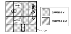
- FIG. 15 is a diagram showing an example of recovery time information displayed on the output device 400 according to the embodiment. Note that FIG. 15 is a diagram corresponding to FIG. Also, the area IDs of the individual areas in FIG. 15 are assumed to be the same as the area IDs shown in FIG.
- the generating unit 130 divides the recoverable area and the non-recoverable area into a schematic diagram or the like showing the target area 700 by color, and furthermore, for the recoverable area, the remote recovery time and the non-recoverable area are displayed.
- image information including the rush time as the recovery time is generated as the recovery information.
- the remote return time is displayed in characters such as “10 seconds” on the presentation unit 410, and for the individual region with region ID: 102, for example, “600 seconds” is displayed. Then, the rush return time is displayed in characters on the presentation unit 410 .
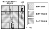
- the recovery time information may include route information indicating a route to a recoverable area.
- FIG. 15A is a diagram showing another example of recovery time information displayed on the output device 400 according to the embodiment.
- the generation unit 130 creates a movement path (for example, the shortest movement path) along which the moving body 300 moves from the current position to the returnable area in a schematic diagram or the like showing the target area 700. is generated as route information.
- the output device 400 displays, for example, an arrow indicating the shortest route to the returnable area of the moving object 300 based on the route information included in the return time information.
- the output device 400 may present the route to the recoverable area instead of or in conjunction with the remote recovery time.
- FIG. 15B is a diagram showing another example of recovery time information displayed on the output device 400 according to the embodiment.
- the generating unit 130 generates a schematic diagram showing a target area 700, for example, when the moving object 300 moves from the current position to a stoppable area (a returnable area in FIG. 15A). (for example, the shortest route) is generated as route information.
- the output device 400 displays, for example, an arrow or the like indicating the shortest route to an area where the moving body 300 can stop, based on the route information included in the return time information.
- the output device 400 may present a route to a stoppable area instead of, or in conjunction with, the remote return time.
- the manner in which the recovery time information is presented to the user is not particularly limited.
- the return time information may be superimposed on an image generated by photographing the surroundings of the mobile object 300 and presented to the user.
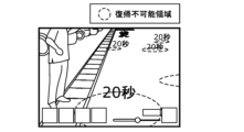
- FIG. 16 is a diagram showing another example of recovery time information displayed on the output device 400 according to the embodiment.
- the generation unit 130 superimposes information indicating the non-recoverable region (eg, the dashed line shown in FIG. 16) on the image generated by capturing the surroundings of the moving body 300.
- the non-recoverable region eg, the dashed line shown in FIG. 16
- an image may be generated in which return time information is superimposed in the vicinity of the information, and return information including information of the generated image may be generated.
- the return determination unit 123 calculates the return time required for the moving body 300 to return from one or more individual areas to the travel route. Also, for example, the generation unit 130 generates recovery information including recovery time information indicating the recovery time calculated by the recovery determination unit 123 .
- the generation unit 130 may generate return information including the shortest point information indicating the individual area that takes the shortest time to return to the travel route among the one or more individual areas.
- the manner in which the shortest point information is presented may be arbitrary.
- the generation unit 130 may generate the return information including the shortest point information by changing the color of the individual area that takes the shortest time to return to the travel route to the color of the other individual areas.
- the generation unit 130 may set the color of the characters indicating the return time of the individual area that takes the shortest time to return to the travel route to be different from the color of the characters indicating the return times of the other individual areas.
- the generation unit 130 generates return information including the shortest point information by, for example, circling only the characters indicating the return time of the individual region that takes the shortest time to return to the travel route. good too.
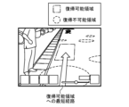
- FIG. 16A is a diagram showing another example of recovery time information displayed on the output device 400 according to the embodiment.
- the generation unit 130 superimposes information indicating an unrecoverable region (for example, the dashed ellipse shown in FIG. 16A) on the image generated by capturing the surroundings of the moving object 300. Then, an image is generated by superimposing information indicating a restorable region (for example, the dashed-dotted rectangle shown in FIG. 16A ), and restoration time information is superimposed near the information, and restoration information including the information of the generated image is generated. may be generated.
- an unrecoverable region for example, the dashed ellipse shown in FIG. 16A
- the output device 400 may present at least one of the recoverable area and the non-recoverable area.
- the generating unit 130 generates, as route information, a movement route (for example, the shortest movement route) along which the moving body 300 moves from the current location to the returnable area.
- the output device 400 displays, for example, an arrow indicating the shortest route to the returnable area of the moving object 300 based on the route information included in the return time information.
- the output device 400 instead of the remote return time, or together with the remote return time, the output device 400 superimposes the route to the returnable area on the image generated by capturing the surroundings of the moving body 300. may be presented.
- the output device 400 is superimposed on the image generated by capturing the surroundings of the moving body 300 to indicate the route to the stoppable area. may be presented.
- the output modes (specifically, display modes) of the output device 400 described above may be combined arbitrarily and realized.
- FIG. 17 is a flow chart showing a third example of the processing procedure of the determination device 100 according to the embodiment.
- the determination device 100 performs steps S130 to S180 and steps S610 to S630 described later for each individual region (S120B).
- the first acquisition unit 111 acquires the road information of the individual area from the storage device 200 (S130).
- the second acquiring unit 112 acquires the object information of the individual area from the moving body 300 (S140).
- the return determination unit 123 determines whether it is possible to return to the travel route from the individual area based on the road information and the object information (S150).
- the recovery determining unit 123 determines that recovery is not possible (No in S150), it determines that the individual area is an unrecoverable area (S160).
- the return determination unit 123 calculates the rush return time for the individual area based on the road information (S610). In this example, the return determination unit 123 acquires the rush return time information of the individual area included in the road information acquired by the first acquisition unit 111 .
- the rush return time may be calculated from the worker's stay position, the position of the moving body 300, and the worker's movement time per unit time.
- the road information may include information indicating the worker's stay position and the worker's travel time per unit time. Further, for example, the road information may include information indicating the position of the individual area such as coordinates.
- the return determining unit 123 may calculate the rush return time based on these information and the information such as the coordinates of the moving body 300 obtained from the GPS receiver or the like.
- the recovery determination unit 123 determines that recovery is possible (Yes in S150), it determines that the individual area is a recovery possible area (S170).
- the return determination unit 123 calculates the remote return time of the individual area based on the road information (S620).
- the output unit 140 outputs the determination result and the calculation result of the restoration determination unit 123 to the output device 400 (S630). Specifically, generation unit 130 generates return information indicating the determination result of return determination unit 123 and the calculation results of the remote return time and rush return time, and output unit 140 outputs the return information generated by generation unit 130. is output to the output device 400 . Thereby, the return information is presented to the user by the presentation unit 410 .
- the determination device 100 collectively acquires road information and object information for a plurality of areas based on the position information of the moving body 300, and performs the processes of steps S150 to S630 without performing steps S130 and S140. may be performed for each individual region.
- the determination device 100 may perform the processing of steps S130 to S620 for each individual region, and then output the determination results for each individual region collectively in step S630.
- the determination device 100 adds determination of whether or not it is necessary to move the moving body 300 backward when returning the moving body 300 to the travel route, in addition to determining whether or not to delete the return route candidate. .
- FIG. 18 is a flow chart showing a modified example of the processing procedure for determining whether or not recovery can be performed by the determination device 100 according to the embodiment. Specifically, FIG. 18 is a flow chart showing another example of details of step S150 executed by the recovery determination unit 123. As shown in FIG.
- the return determination unit 123 calculates one or more return route candidates for the moving body 300 when returning to the travel route from the individual area based on the road information (S210).
- the return determination unit 123 performs steps S230 to S250 and steps S710 to S720 described later for each calculated return route candidate (S220A).
- the return determining unit 123 determines whether or not it is necessary to move the moving body 300 backward after the moving body 300 has traveled along the return route of the return route candidate and returned to the travel route (S710).
- the return determination unit 123 determines whether or not the distance to move back (retreat distance) is equal to or greater than a predetermined distance (S720).
- the predetermined distance may be determined arbitrarily and is not particularly limited. Information indicating the predetermined distance may be stored in the storage device 200 and acquired by the first acquisition unit 111 .
- the return determination unit 123 determines that the retreat distance is greater than or equal to the predetermined distance (Yes in S720), it deletes it from the return route candidates (S250).
- the return determining unit 123 determines that the moving body 300 does not need to be moved backward (No in S710), or if it determines that the backward movement distance is less than a predetermined distance (No in S720), the return determination unit 123 returns a , it is determined whether or not the moving object 300 running on the return route candidate violates traffic rules (S230).
- the return determination unit 123 determines whether or not the moving body 300 needs to move backward before the moving body 300 returns to the travel route from one or more regions. It is determined whether or not the moving object 300 can return to the travel route from one or more points based on the determination result of whether or not it is necessary to return to the travel route. Specifically, for example, when the return determination unit 123 determines that the moving object 300 does not need to move backward, it determines that the moving object 300 can return to the travel route from one or more individual areas. On the other hand, for example, when the return determination unit 123 determines that the moving body 300 needs to move backward, it calculates the backward movement distance that the moving body 300 moves back from one or more individual areas until it returns to the travel route.
- the return determination unit 123 determines that the moving object 300 cannot return to the travel route from one or more points (that is, deletes it from the return route candidates). ), and if the retreat distance is less than a predetermined distance, it is determined that the moving object 300 can return to the travel route from one or more individual regions (that is, it is not deleted from the return route candidates).
- the return determination unit 123 determines whether an object exists on the return route candidate based on the object information. judge.
- the return determination unit 123 determines that the moving object 300 running on the return route candidate violates the traffic rules (Yes in S230), or determines that an object exists on the return route candidate (Yes in S240). ), and delete the return route candidate (S250).
- the return determination unit 123 determines whether or not there is a return route candidate (S260).
- the return determination unit 123 determines that there is no return route candidate (No in S260), it determines that it is impossible to return to the travel route from the individual area (S270).
- the return determination unit 123 determines that there is a return route candidate (Yes in S260), it determines that it is possible to return to the travel route from the individual area (S280).
- FIG. 19 is a flow chart showing the processing procedure of the information output device according to the embodiment.
- FIG. 19 is a flowchart showing an information output method in the information output device according to the embodiment (in other words, executed by the information output device), that is, the information output method according to the embodiment.
- the information output device acquires the first information related to the area including the travel route along which the moving body 300 travels (S10).
- the first information is, for example, the road information described above.
- the information output device acquires second information about objects existing in the area (S20).
- the second information is, for example, the object information described above.
- the information output device outputs third information regarding the return of the moving body 300 to the traveling route from one or more points where the moving body 300 can stop in the area.
- the information output device may determine whether the area is a stoppable area based on the rule information described above, for example, or may determine whether the area is a stoppable area based on the object information described above, for example. You can judge.
- the information output device outputs, for example, information indicating the determination result as the third information.
- the third information may be, for example, the return information described above.
- the information output device outputs the third information (S40).
- the information output device presents (for example, displays) the third information to the user by outputting the third information to, for example, a display included in the information output device or the external device.
- the output device 400 such as a display presents the information about the return to the user who drives the moving object 300 and stops it, so that the user can see the point where the return route is short or the time required for the return is short. For example, a point at which the moving body 300 can be efficiently returned can be grasped. Therefore, according to the information output method according to one aspect of the present disclosure, it is possible to appropriately select a point at which the moving body 300 can be efficiently returned to the travel route, so that the moving body 300 can be made to travel efficiently.
- the information output device determines whether or not the moving object 300 can return to the travel route from one or more points based on at least one of the first information and the second information. Then, the third information including return possibility information indicating whether or not the moving object 300 can return to the travel route from one or more points is generated.
- the information output device determines that the moving object 300 can automatically drive, the travel route is a route on which the moving object 300 can travel automatically, and in the generation of the third information, the moving object 300 automatically Determining whether or not it is possible to return to the travel route from one or more points by driving, and includes return availability information indicating whether or not the moving object 300 can automatically return to the travel route from one or more points. Generate third information.
- the mobile body 300 can be appropriately stopped at a point where it can return to the travel route by automatic operation.
- the information output device calculates a return route for the moving body 300 to return to the traveling route from one or more points based on the first information, Based on at least one of them, it is determined whether or not the moving object 300 can travel the return route and reach the traveling route, and if it is determined that the traveling route can be reached, the moving object 300 returns to the traveling route from one or more points. When it is determined that it is possible and it is determined that the travel route cannot be reached, it is determined that the moving body 300 cannot return to the travel route.
- the information output device determines whether or not the moving body 300 needs to move backward until the moving body 300 returns to the travel route from one or more points. Based on the determination result of whether or not the body 300 needs to retreat, it is determined whether or not the moving body 300 can return to the travel route from one or more points.
- the information output device determines that the moving body 300 can return to the travel route from one or more points, and determines that the moving body 300 does not need to retreat. If it is determined that there is, the moving body 300 calculates the retreat distance from one or more points until it returns to the traveling route, and if the retreat distance is equal to or greater than a predetermined distance, the moving body 300 returns to one or more points If the retreat distance is less than the predetermined distance, it is determined that the moving body 300 can return to the travel route from one or more points.
- the information output device determines whether or not the moving object 300 can stop at one or more points based on at least one of the first information and the second information.
- Third information is generated that includes stop permission/prohibition information indicating whether or not it is possible.
- the information output device calculates the return time required for the moving body 300 to return to the travel route from one or more points, and generates the third information including the return time information indicating the return time. to generate
- the user can compare the recovery time required for recovery by an emergency worker and the recovery time required for automatic recovery, and determine which recovery time is shorter.
- the information output device in the generation of the third information, the information output device generates the third information including the shortest point information indicating the point that takes the shortest time to return to the travel route among the one or more points. .
- the user can easily grasp the point where the moving body 300 can return to the travel route most efficiently in time.
- the information output device in generating the third information, the information output device generates the third information based on at least one of the first information and the second information and performance information indicating the running performance of the moving object 300 .
- the point at which the moving body 300 can be returned to the travel route can be more appropriately selected according to the performance of the moving body 300.
- the information output device when generating the third information, the information output device generates the third information based on at least one of the first information and the second information and traffic information indicating the traffic volume in the area.
- the moving body 300 may or may not be able to travel automatically, such as areas with heavy traffic. In other words, there are areas where automatic return is possible and where it is not possible depending on the traffic volume. Therefore, according to this, the point at which the mobile body 300 can be returned to the travel route can be more appropriately selected according to the traffic volume.
- the first information includes at least rule information indicating traffic rules in the area, travel permission/prohibition information indicating whether or not the moving object 300 can travel in the area, and distance information indicating the distance from the area to the travel route. including any
- the second information indicates whether an object exists in the area detected by the sensor unit 310 arranged on the moving body 300 .
- the one or more points include the point where the moving object 300 is located.
- the information output device indicates in the first color, among the one or more points, points at which it is possible to return to the travel route, and points at which it is impossible to return to the travel route in the first color. produces third information containing image information shown in a different second color.
- the image information is presented by the presentation unit 410 to the user who drives the moving body 300 and stops it, so that the user can intuitively know the points at which the moving body 300 can and cannot be returned to the traveling route. can be easily grasped.
- the mobile object 300 operates at least by remote control by a terminal connected via a network, and the information output device outputs the third information to the terminal when outputting the third information.
- the moving body 300 can be stopped at a point where the moving body 300 can be returned to the travel route even by remote control.
- the information output device may be implemented by a memory storing a control program for performing the above-described processing and a processor executing the control program.
- the information output device includes a first acquisition unit 111 that acquires first information about an area including the travel route along which the moving object 300 travels, and second information about an object that exists in the area. Third information about the return of the moving body 300 to the traveling route from one or more points where the moving body 300 can stop in the region, based on the second obtaining unit 112 to obtain and at least one of the first information and the second information and an output unit 140 that outputs the third information.
- the information output device does not have to include the rule determination unit 121.
- the information output device does not have to include the interference determination unit 122 .
- the sensor unit 310 may be arranged on a construction material such as a utility pole, instead of the mobile object 300 .
- step S110 when an event occurs in step S110, the processing after step S120 is performed.
- the processing from step S120 onward may always be performed.
- step S110 may not be performed.
- FIG. an example of presenting an unrecoverable area is shown in FIG.
- the information output system 500 includes the determination device 100, the storage device 200, the moving body 300, and the output device 400, but the information output system according to the present disclosure It may also be implemented as a single device such as a vehicle.
- the processing units such as the determination unit 120 included in the determination device 100, the moving body control unit 320, and the output device control unit 430 may be implemented by the same memory, processor, or the like.
- the travel route is a route automatically driven by the moving body 300, but may be a route calculated by a navigation system or the like.
- the mobile object 300 may be a vehicle that the user rides on and drives instead of a vehicle that is remotely controlled.
- the determination device 100 acquires an instruction from the user through an operation unit such as a touch panel (not shown) provided in the determination device 100
- the determination device 100 moves in the target region based on at least one of the first information and the second information.
- Third information regarding the return of the moving body 300 from one or more points at which the body 300 can stop to the travel route calculated by the navigation system or the like may be generated.
- the output device 400 may be arranged on the mobile object 300 to present the third information thus generated.
- the moving body 300 may determine a point at which to stop the moving body 300 based on the third information, and move to the determined point.
- the present disclosure can be implemented as a program for causing a processor to execute the steps included in the information output method.
- the present disclosure can be implemented as a non-temporary computer-readable non-temporary recording medium, such as a CD-ROM, on which the program is recorded.
- each step is executed. That is, each step is executed by the CPU obtaining data from a memory, an input/output circuit, or the like, performing an operation, or outputting the operation result to the memory, an input/output circuit, or the like.
- hardware resources such as a computer's CPU (Central Processing Unit), memory, and input/output circuits.
- each step is executed by the CPU obtaining data from a memory, an input/output circuit, or the like, performing an operation, or outputting the operation result to the memory, an input/output circuit, or the like.
- each component included in the information output device may be configured with dedicated hardware or implemented by executing a software program suitable for each component.
- Each component may be realized by reading and executing a software program recorded in a recording medium such as a hard disk or a semiconductor memory by a program execution unit such as a CPU or processor.
- a part or all of the functions of the information output device according to the above embodiment are typically realized as an LSI, which is an integrated circuit. These may be made into one chip individually, or may be made into one chip so as to include part or all of them. Further, circuit integration is not limited to LSIs, and may be realized by dedicated circuits or general-purpose processors.
- An FPGA Field Programmable Gate Array
- a reconfigurable processor that can reconfigure the connections and settings of the circuit cells inside the LSI may be used.
- the present disclosure also includes various modifications in which a person skilled in the art makes modifications to each embodiment of the present disclosure, as long as they do not deviate from the gist of the present disclosure.
- the present disclosure can be applied, for example, to mobile objects such as autonomous vehicles that can be remotely controlled.
- determination device 110 acquisition unit 111 first acquisition unit 112 second acquisition unit 120 determination unit 121 rule determination unit 122 interference determination unit 123 return determination unit 130 generation unit 140 output unit 200 storage device 210 road information database 300 moving body 310 sensor unit 320 moving body control unit 400 output device 410 presentation unit 420 operation unit 430 output device control unit 500 information output system 600 pedestrian 700 target area
Landscapes
- Engineering & Computer Science (AREA)
- Radar, Positioning & Navigation (AREA)
- Remote Sensing (AREA)
- Physics & Mathematics (AREA)
- General Physics & Mathematics (AREA)
- Automation & Control Theory (AREA)
- Aviation & Aerospace Engineering (AREA)
- Human Computer Interaction (AREA)
- Transportation (AREA)
- Mechanical Engineering (AREA)
- Navigation (AREA)
- Traffic Control Systems (AREA)
Abstract
Description
自動運転する移動体の運用では、例えば、目的地まで所定の走行経路で移動体を走行させる。所定の走行経路で走行するように移動体に自動運転させている際に、天候または交通状況等の変化によって、移動体が自動運転できなくなる場合がある。このような場合には、遠隔操作等によって移動体を手動で所定の走行経路から退避させて停止させることが必要になるときがある。このようなときに、適切な場所に移動体を退避させないと、自動運転によって移動体を所定の走行経路に復帰させることができない場合がある。このような場合には、遠隔操作等によって移動体を手動で所定の走行経路に復帰させたり、場合によっては作業者が移動体に乗り込んで移動体を運転することで、所定の走行経路に復帰させる必要がある。このように、移動体を適切な位置に停止させないと、目的地まで移動体を走行させる効率が低下する。
[構成]
まず、情報出力システムの構成について説明する。
続いて、判定装置100の処理手順について説明する。なお、以下で説明する各例のフローチャートにおいては実質的に同様の処理については同様の符号を付し、同じ処理については説明を簡略化または省略する場合がある。
まず、判定装置100の処理手順の第1例について説明する。第1例では、判定装置100は、各個別領域が移動体300を停止させた場合に走行経路に復帰できる領域であるか否かを判定し、判定結果を含む復帰情報を生成して出力する。
続いて、判定装置100の処理手順の第2例について説明する。第2例では、判定装置100は、各個別領域について移動体300が停止可能であるか否かを判定し、停止可能であると判定された個別領域が移動体300を停止させた場合に走行経路に復帰できる領域であるか否かを判定し、これらの判定結果を含む復帰情報を生成して出力する。
続いて、判定装置100の処理手順の第3例について説明する。第3例では、判定装置100は、各個別領域が移動体300を停止させた場合に走行経路に復帰できる領域であるか否かを判定し、さらに、復帰にかかる時間である復帰時間を算出し、判定結果と復帰時間を示す復帰時間情報とを含む復帰情報を生成して出力する。
続いて、判定装置100の復帰可否判定処理の処理手順の変形例について説明する。変形例では、判定装置100は、復帰経路候補を削除するか否かの判定に、移動体300を走行経路に復帰させる際に移動体300を後退させる必要があるか否かの判定を追加する。
以上説明した判定装置100が一例である情報出力装置は、以下の処理を行う。
以上、本開示の一つまたは複数の態様に係る情報出力方法および情報出力装置について、実施の形態に基づいて説明したが、本開示は、上記実施の形態に限定されるものではない。本開示の趣旨を逸脱しない限り、当業者が思いつく各種変形を各実施の形態に施したものや、異なる実施の形態、例えば、上記した第1例~第3例および変形例における構成要素および各種処理を組み合わせて構築される形態も、本開示の一つまたは複数の態様の範囲内に含まれてもよい。
110 取得部
111 第1取得部
112 第2取得部
120 判定部
121 ルール判定部
122 妨害判定部
123 復帰判定部
130 生成部
140 出力部
200 記憶装置
210 道路情報データベース
300 移動体
310 センサ部
320 移動体制御部
400 出力装置
410 提示部
420 操作部
430 出力装置制御部
500 情報出力システム
600 歩行者
700 対象領域
Claims (17)
- 情報出力装置における情報出力方法であって、
移動体が走行する走行経路を含む領域に関する第1情報を取得し、
前記領域に存在する物体に関する第2情報を取得し、
前記第1情報および前記第2情報の少なくとも一方に基づき、前記領域において前記移動体が停止しうる1以上の地点からの前記移動体の前記走行経路への復帰に関する第3情報を生成し、
前記第3情報を出力する、
情報出力方法。 - 前記第3情報の生成では、
前記第1情報および前記第2情報の少なくとも一方に基づき、前記移動体が前記1以上の地点から前記走行経路へ復帰可能であるか否かを判定し、
前記移動体が前記1以上の地点から前記走行経路に復帰可能であるか否かを示す復帰可否情報を含む前記第3情報を生成する、
請求項1に記載の情報出力方法。 - 前記移動体は、自動運転可能であり、
前記走行経路は、前記移動体が自動運転で走行可能な経路であり、
前記第3情報の生成では、前記移動体が自動運転により前記1以上の地点から前記走行経路に復帰可能であるか否かを判定し、
前記移動体が自動運転で前記1以上の地点から前記走行経路に復帰可能であるか否かを示す前記復帰可否情報を含む前記第3情報を生成する、
請求項2に記載の情報出力方法。 - 前記第3情報の生成では、
前記第1情報に基づき、前記移動体が前記1以上の地点から前記走行経路に復帰する復帰経路を算出し、
前記第1情報および前記第2情報の少なくとも一方に基づき、前記移動体が前記復帰経路を走行して前記走行経路に到達できるか否かを判定し、
前記走行経路に到達できると判定した場合、前記移動体が前記1以上の地点から前記走行経路に復帰可能であると判定し、
前記走行経路に到達できないと判定した場合、前記移動体が前記走行経路に復帰不可能であると判定する、
請求項2または3に記載の情報出力方法。 - 前記第3情報の生成では、
前記移動体が前記1以上の地点から前記走行経路に復帰するまでに、前記移動体が後退する必要があるか否かを判定し、
前記移動体が後退する必要があるか否かの判定結果に基づき、前記移動体が前記1以上の地点から前記走行経路に復帰可能であるか否かを判定する、
請求項2~4のいずれか1項に記載の情報出力方法。 - 前記移動体が後退する必要がないと判定した場合、前記移動体が前記1以上の地点から前記走行経路に復帰可能であると判定し、
前記移動体が後退する必要があると判定した場合、前記移動体が前記1以上の地点から前記走行経路に復帰するまでに後退する後退距離を算出し、
前記後退距離が所定の距離以上である場合、前記移動体が前記1以上の地点から前記走行経路に復帰不可能であると判定し、
前記後退距離が前記所定の距離未満である場合、前記移動体が前記1以上の地点から前記走行経路に復帰可能であると判定する、
請求項5に記載の情報出力方法。 - 前記第3情報の生成では、
前記第1情報および前記第2情報の少なくとも一方に基づき、前記移動体が前記1以上の地点に停止可能であるか否かを判定し、
停止可能であるか否かを示す停止可否情報を含む前記第3情報を生成する、
請求項1~6のいずれか1項に記載の情報出力方法。 - 前記第3情報の生成では、
前記移動体が前記1以上の地点から前記走行経路への復帰にかかる復帰時間を算出し、
前記復帰時間を示す復帰時間情報を含む前記第3情報を生成する、
請求項1~7のいずれか1項に記載の情報出力方法。 - 前記第3情報の生成では、前記1以上の地点のうち、前記走行経路への復帰にかかる時間が最も時間の短い地点を示す最短地点情報を含む前記第3情報を生成する、
請求項8に記載の情報出力方法。 - 前記第3情報の生成では、前記第1情報および前記第2情報の少なくとも一方と、前記移動体の走行性能を示す性能情報とも基づき、前記第3情報を生成する、
請求項1~9のいずれか1項に記載の情報出力方法。 - 前記第3情報の生成では、前記第1情報および前記第2情報の少なくとも一方と、前記領域における交通量を示す交通量情報とも基づき、前記第3情報を生成する、
請求項1~10のいずれか1項に記載の情報出力方法。 - 前記第1情報は、前記領域における交通ルールを示すルール情報、前記領域において前記移動体が走行可能か否かを示す走行可否情報、および、前記領域から前記走行経路までの距離を示す距離情報の少なくともいずれかを含む、
請求項1~11のいずれか1項に記載の情報出力方法。 - 前記第2情報は、前記移動体に配置されたセンサ部が検出した、前記領域に前記物体が存在するか否かを示す、
請求項1~12のいずれか1項に記載の情報出力方法。 - 前記1以上の地点は、前記移動体が位置する地点を含む、
請求項1~13のいずれか1項に記載の情報出力方法。 - 前記第3情報の生成では、
前記1以上の地点のうち、前記走行経路に復帰可能な地点を第1色で示し、前記走行経路に復帰不可能な地点を前記第1色とは異なる第2色で示す画像情報を含む前記第3情報を生成する、
請求項1~14のいずれか1項に記載の情報出力方法。 - 前記移動体は、少なくともネットワークを介して接続された端末による遠隔操作によって動作し、
前記第3情報の出力では、前記第3情報を前記端末に出力する、
請求項1~15のいずれか1項に記載の情報出力方法。 - 移動体が走行する走行経路を含む領域に関する第1情報を取得する第1取得部と、
前記領域に存在する物体に関する第2情報を取得する第2取得部と、
前記第1情報および前記第2情報の少なくとも一方に基づき、前記領域において前記移動体が停止しうる1以上の地点からの前記移動体の前記走行経路への復帰に関する第3情報を生成する生成部と、
前記第3情報を出力する出力部と、を備える、
情報出力装置。
Priority Applications (4)
| Application Number | Priority Date | Filing Date | Title |
|---|---|---|---|
| JP2023567526A JPWO2023112367A1 (ja) | 2021-12-13 | 2022-07-11 | |
| CN202280081420.XA CN118382882A (zh) | 2021-12-13 | 2022-07-11 | 信息输出方法以及信息输出装置 |
| EP22906904.2A EP4451082A4 (en) | 2021-12-13 | 2022-07-11 | INFORMATION OUTPUT METHOD AND INFORMATION OUTPUT DEVICE |
| US18/679,859 US20240319733A1 (en) | 2021-12-13 | 2024-05-31 | Information output method and information output device |
Applications Claiming Priority (2)
| Application Number | Priority Date | Filing Date | Title |
|---|---|---|---|
| JP2021202070 | 2021-12-13 | ||
| JP2021-202070 | 2021-12-13 |
Related Child Applications (1)
| Application Number | Title | Priority Date | Filing Date |
|---|---|---|---|
| US18/679,859 Continuation US20240319733A1 (en) | 2021-12-13 | 2024-05-31 | Information output method and information output device |
Publications (1)
| Publication Number | Publication Date |
|---|---|
| WO2023112367A1 true WO2023112367A1 (ja) | 2023-06-22 |
Family
ID=86774200
Family Applications (1)
| Application Number | Title | Priority Date | Filing Date |
|---|---|---|---|
| PCT/JP2022/027243 Ceased WO2023112367A1 (ja) | 2021-12-13 | 2022-07-11 | 情報出力方法、および、情報出力装置 |
Country Status (5)
| Country | Link |
|---|---|
| US (1) | US20240319733A1 (ja) |
| EP (1) | EP4451082A4 (ja) |
| JP (1) | JPWO2023112367A1 (ja) |
| CN (1) | CN118382882A (ja) |
| WO (1) | WO2023112367A1 (ja) |
Cited By (2)
| Publication number | Priority date | Publication date | Assignee | Title |
|---|---|---|---|---|
| WO2025142311A1 (ja) * | 2023-12-27 | 2025-07-03 | パナソニックオートモーティブシステムズ株式会社 | 車両制御方法および車両制御装置 |
| US20250225492A1 (en) * | 2024-01-05 | 2025-07-10 | International Business Machines Corporation | Context-aware payments using indoor positioning systems |
Citations (4)
| Publication number | Priority date | Publication date | Assignee | Title |
|---|---|---|---|---|
| JP2007331652A (ja) | 2006-06-16 | 2007-12-27 | Toyota Motor Corp | 車両停止装置 |
| WO2015060863A1 (en) * | 2013-10-25 | 2015-04-30 | Intel Corporation | Navigation guidance including provision of stops |
| WO2019073576A1 (ja) * | 2017-10-12 | 2019-04-18 | 本田技研工業株式会社 | 車両並びにその制御装置及び制御方法 |
| JP2020164017A (ja) * | 2019-03-29 | 2020-10-08 | 本田技研工業株式会社 | 車両制御システム |
Family Cites Families (7)
| Publication number | Priority date | Publication date | Assignee | Title |
|---|---|---|---|---|
| JP4849061B2 (ja) * | 2007-12-06 | 2011-12-28 | トヨタ自動車株式会社 | 車両用逆走防止装置 |
| JP5482320B2 (ja) * | 2010-03-11 | 2014-05-07 | 株式会社デンソー | 車両用運転支援装置 |
| WO2013145146A1 (ja) * | 2012-03-28 | 2013-10-03 | パイオニア株式会社 | ナビゲーション装置、ナビゲーション方法及びナビゲーションプログラム |
| JP6451584B2 (ja) * | 2015-10-09 | 2019-01-16 | 株式会社デンソー | 情報処理装置 |
| DE102017210081B4 (de) * | 2017-06-14 | 2019-10-17 | Elektrobit Automotive Gmbh | Verfahren und Vorrichtung zum Bestimmen von nicht zu befahrenden Bereichen |
| KR20200071840A (ko) * | 2018-12-03 | 2020-06-22 | 현대자동차주식회사 | 자율주행차량을 지원하는 시스템 및 방법 |
| CN112805763B (zh) * | 2021-01-29 | 2022-04-22 | 华为技术有限公司 | 一种道路预警的方法、装置和系统 |
-
2022
- 2022-07-11 CN CN202280081420.XA patent/CN118382882A/zh active Pending
- 2022-07-11 WO PCT/JP2022/027243 patent/WO2023112367A1/ja not_active Ceased
- 2022-07-11 EP EP22906904.2A patent/EP4451082A4/en not_active Withdrawn
- 2022-07-11 JP JP2023567526A patent/JPWO2023112367A1/ja active Pending
-
2024
- 2024-05-31 US US18/679,859 patent/US20240319733A1/en active Pending
Patent Citations (4)
| Publication number | Priority date | Publication date | Assignee | Title |
|---|---|---|---|---|
| JP2007331652A (ja) | 2006-06-16 | 2007-12-27 | Toyota Motor Corp | 車両停止装置 |
| WO2015060863A1 (en) * | 2013-10-25 | 2015-04-30 | Intel Corporation | Navigation guidance including provision of stops |
| WO2019073576A1 (ja) * | 2017-10-12 | 2019-04-18 | 本田技研工業株式会社 | 車両並びにその制御装置及び制御方法 |
| JP2020164017A (ja) * | 2019-03-29 | 2020-10-08 | 本田技研工業株式会社 | 車両制御システム |
Non-Patent Citations (1)
| Title |
|---|
| See also references of EP4451082A4 |
Cited By (2)
| Publication number | Priority date | Publication date | Assignee | Title |
|---|---|---|---|---|
| WO2025142311A1 (ja) * | 2023-12-27 | 2025-07-03 | パナソニックオートモーティブシステムズ株式会社 | 車両制御方法および車両制御装置 |
| US20250225492A1 (en) * | 2024-01-05 | 2025-07-10 | International Business Machines Corporation | Context-aware payments using indoor positioning systems |
Also Published As
| Publication number | Publication date |
|---|---|
| EP4451082A1 (en) | 2024-10-23 |
| EP4451082A4 (en) | 2025-04-30 |
| US20240319733A1 (en) | 2024-09-26 |
| CN118382882A (zh) | 2024-07-23 |
| JPWO2023112367A1 (ja) | 2023-06-22 |
Similar Documents
| Publication | Publication Date | Title |
|---|---|---|
| CN106611497B (zh) | 交通量预测系统及预测方法、车辆用显示装置以及车辆 | |
| US10071745B2 (en) | Automated drive assisting system, automated drive assisting method, and computer program | |
| KR101751298B1 (ko) | 차량 경로 예측 방법 및 장치 | |
| JP5229293B2 (ja) | 車両用運転支援装置 | |
| EP3009798B1 (en) | Providing alternative road navigation instructions for drivers on unfamiliar roads | |
| US20170197635A1 (en) | Automatic driving assistance system, automatic driving assistance method, and computer program | |
| US20190064827A1 (en) | Self-driving assistance device and computer program | |
| US9304011B2 (en) | Map display device | |
| JP6305650B2 (ja) | 自動運転装置及び自動運転方法 | |
| US20240319733A1 (en) | Information output method and information output device | |
| US12055409B2 (en) | Uncontrolled intersection detection and warning system | |
| JP2010025709A (ja) | 運転支援装置、運転支援方法、運転支援プログラム、およびコンピュータに読み取り可能な記録媒体 | |
| JP2018081420A (ja) | 逆走判定方法およびそれを利用した逆走判定装置、プログラム | |
| JP6949512B2 (ja) | 情報出力装置及び情報出力方法 | |
| JP2010140265A (ja) | 走行支援装置、方法およびプログラム | |
| JP4381465B2 (ja) | 経路誘導装置、経路誘導方法、経路誘導プログラムおよびコンピュータに読み取り可能な記録媒体 | |
| JP2009092586A (ja) | 駐車場検索システム及びプログラム | |
| JP7593452B2 (ja) | 運転支援システム、運転支援方法およびプログラム | |
| CN104024799B (zh) | 导航装置、导航方法 | |
| JP2007132828A (ja) | ナビゲーション装置および経路探索方法 | |
| JP2023022910A (ja) | 情報処理装置、及び情報処理方法 | |
| JP6921023B2 (ja) | 情報処理装置、情報処理方法、及びプログラム | |
| US12536911B2 (en) | Information processing device | |
| US20200166370A1 (en) | Notification control apparatus and notification control method | |
| JP6852022B2 (ja) | 地図情報作成装置、地図情報作成方法、地図情報作成プログラム及び記録媒体 |
Legal Events
| Date | Code | Title | Description |
|---|---|---|---|
| 121 | Ep: the epo has been informed by wipo that ep was designated in this application |
Ref document number: 22906904 Country of ref document: EP Kind code of ref document: A1 |
|
| WWE | Wipo information: entry into national phase |
Ref document number: 202280081420.X Country of ref document: CN Ref document number: 2023567526 Country of ref document: JP |
|
| WWE | Wipo information: entry into national phase |
Ref document number: 2022906904 Country of ref document: EP |
|
| NENP | Non-entry into the national phase |
Ref country code: DE |
|
| ENP | Entry into the national phase |
Ref document number: 2022906904 Country of ref document: EP Effective date: 20240715 |
|
| WWW | Wipo information: withdrawn in national office |
Ref document number: 2022906904 Country of ref document: EP |