WO2023112459A1 - Actionneur hydraulique - Google Patents
Actionneur hydraulique Download PDFInfo
- Publication number
- WO2023112459A1 WO2023112459A1 PCT/JP2022/038447 JP2022038447W WO2023112459A1 WO 2023112459 A1 WO2023112459 A1 WO 2023112459A1 JP 2022038447 W JP2022038447 W JP 2022038447W WO 2023112459 A1 WO2023112459 A1 WO 2023112459A1
- Authority
- WO
- WIPO (PCT)
- Prior art keywords
- tube
- actuator
- main body
- diameter
- sealing member
- Prior art date
- Legal status (The legal status is an assumption and is not a legal conclusion. Google has not performed a legal analysis and makes no representation as to the accuracy of the status listed.)
- Ceased
Links
Images



Classifications
-
- F—MECHANICAL ENGINEERING; LIGHTING; HEATING; WEAPONS; BLASTING
- F15—FLUID-PRESSURE ACTUATORS; HYDRAULICS OR PNEUMATICS IN GENERAL
- F15B—SYSTEMS ACTING BY MEANS OF FLUIDS IN GENERAL; FLUID-PRESSURE ACTUATORS, e.g. SERVOMOTORS; DETAILS OF FLUID-PRESSURE SYSTEMS, NOT OTHERWISE PROVIDED FOR
- F15B15/00—Fluid-actuated devices for displacing a member from one position to another; Gearing associated therewith
- F15B15/08—Characterised by the construction of the motor unit
- F15B15/10—Characterised by the construction of the motor unit the motor being of diaphragm type
- F15B15/103—Characterised by the construction of the motor unit the motor being of diaphragm type using inflatable bodies that contract when fluid pressure is applied, e.g. pneumatic artificial muscles or McKibben-type actuators
-
- F—MECHANICAL ENGINEERING; LIGHTING; HEATING; WEAPONS; BLASTING
- F16—ENGINEERING ELEMENTS AND UNITS; GENERAL MEASURES FOR PRODUCING AND MAINTAINING EFFECTIVE FUNCTIONING OF MACHINES OR INSTALLATIONS; THERMAL INSULATION IN GENERAL
- F16L—PIPES; JOINTS OR FITTINGS FOR PIPES; SUPPORTS FOR PIPES, CABLES OR PROTECTIVE TUBING; MEANS FOR THERMAL INSULATION IN GENERAL
- F16L33/00—Arrangements for connecting hoses to rigid members; Rigid hose-connectors, i.e. single members engaging both hoses
- F16L33/20—Undivided rings, sleeves, or like members contracted on the hose or expanded inside the hose by means of tools; Arrangements using such members
- F16L33/207—Undivided rings, sleeves, or like members contracted on the hose or expanded inside the hose by means of tools; Arrangements using such members only a sleeve being contracted on the hose
- F16L33/2071—Undivided rings, sleeves, or like members contracted on the hose or expanded inside the hose by means of tools; Arrangements using such members only a sleeve being contracted on the hose the sleeve being a separate connecting member
-
- F—MECHANICAL ENGINEERING; LIGHTING; HEATING; WEAPONS; BLASTING
- F15—FLUID-PRESSURE ACTUATORS; HYDRAULICS OR PNEUMATICS IN GENERAL
- F15B—SYSTEMS ACTING BY MEANS OF FLUIDS IN GENERAL; FLUID-PRESSURE ACTUATORS, e.g. SERVOMOTORS; DETAILS OF FLUID-PRESSURE SYSTEMS, NOT OTHERWISE PROVIDED FOR
- F15B15/00—Fluid-actuated devices for displacing a member from one position to another; Gearing associated therewith
- F15B15/08—Characterised by the construction of the motor unit
- F15B15/14—Characterised by the construction of the motor unit of the straight-cylinder type
- F15B15/1423—Component parts; Constructional details
- F15B15/1438—Cylinder to end cap assemblies
-
- F—MECHANICAL ENGINEERING; LIGHTING; HEATING; WEAPONS; BLASTING
- F16—ENGINEERING ELEMENTS AND UNITS; GENERAL MEASURES FOR PRODUCING AND MAINTAINING EFFECTIVE FUNCTIONING OF MACHINES OR INSTALLATIONS; THERMAL INSULATION IN GENERAL
- F16L—PIPES; JOINTS OR FITTINGS FOR PIPES; SUPPORTS FOR PIPES, CABLES OR PROTECTIVE TUBING; MEANS FOR THERMAL INSULATION IN GENERAL
- F16L33/00—Arrangements for connecting hoses to rigid members; Rigid hose-connectors, i.e. single members engaging both hoses
- F16L33/22—Arrangements for connecting hoses to rigid members; Rigid hose-connectors, i.e. single members engaging both hoses with means not mentioned in the preceding groups for gripping the hose between inner and outer parts
- F16L33/225—Arrangements for connecting hoses to rigid members; Rigid hose-connectors, i.e. single members engaging both hoses with means not mentioned in the preceding groups for gripping the hose between inner and outer parts a sleeve being movable axially
Definitions
- the present invention relates to a fluid pressure actuator that expands and contracts a tube using gas or liquid, and specifically to a so-called McKibben type fluid pressure actuator.
- a fluid pressure actuator for expanding and contracting a tube as described above has a rubber tube (tubular body) that expands and contracts by air pressure, and a sleeve (network reinforcement structure) that covers the outer peripheral surface of the tube.
- a structure (the so-called McKibben type) is widely used.
- Both ends of the actuator main body composed of the tube and the sleeve are sealed using sealing members made of metal.
- the sleeve is a cylindrical structure woven with high-tensile fibers such as polyamide fibers or metal cords, and regulates the expansion movement of the tube within a predetermined range.
- a locking member (locking ring) is used to form the sealing member.
- a structure is known in which a sleeve is locked to a flange portion and both ends of an actuator main body are crimped using a restraining member (crimping ring) (for example, Patent Document 1).
- the McKibben type fluid pressure actuator as described above may be used in an environment where expansion and contraction are repeated extremely many times (for example, about 10,000 to 100,000 times).
- both ends of the tube in the axial direction in the vicinity of the restraining member are more likely to expand, and when the expansion and contraction operations are repeated many times, the ends eventually expand. It becomes a bulging shape like a gourd, and its durability decreases.
- the following disclosure has been made in view of this situation, and aims to provide a fluid pressure actuator that can prevent the mesh of the sleeve in the vicinity of the restraining member from expanding and further improve durability.
- a fluid pressure actuator comprising a main body and a sealing mechanism for sealing an end of the actuator main body in an axial direction of the actuator main body, wherein the actuator main body is inserted through the sealing mechanism.
- a restraining member provided on the outer peripheral surface of the actuator main body inserted through the sealing member to restrain the actuator main body; and a locking member locking the sleeve to the sealing member.
- the sealing member includes a body portion through which the tube is inserted, and the outer diameter of the body portion is larger than the inner diameter of the portion of the tube that is not inserted through the body portion.
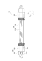
- FIG. 1 is a side view of the hydraulic actuator 10.
- FIG. FIG. 2 is a partially exploded perspective view of the fluid pressure actuator 10.
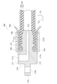
- FIG. 3 is a partial cross-sectional view of the sealing mechanism 200 along the axial direction DAX .
- FIG. 4 is a partial cross-sectional view along the axial direction DAX of the sealing mechanism 200 before assembly.
- 5(a)-(d) are partial cross-sectional and contour views along the axial direction DAX of the sealing mechanism 200 and the sealing mechanism 200P.
- FIG. 1 is a side view of a fluid pressure actuator 10 according to this embodiment.
- the fluid pressure actuator 10 includes an actuator main body 100, a sealing mechanism 200 and a sealing mechanism 300.
- the sealing mechanism 200 As shown in FIG. 1, the sealing mechanism 300 is a sealing mechanism.
- sealing mechanism 200 and the sealing mechanism 300 seal both ends of the actuator main body 100 in the axial direction DAX .
- sealing mechanism 200 includes sealing member 210 and crimp ring 230 .
- the sealing member 210 seals the end of the actuator body 100 in the axial direction DAX .
- the crimping ring 230 crimps the actuator main body 100 together with the sealing member 210 (which may be described as "crimping").
- an indentation 231 is formed as a mark resulting from caulking of the caulking ring 230 by a jig.
- the difference between the sealing mechanism 200 and the sealing mechanism 300 is whether or not a connection port 211a for fluid is provided.
- the actuator main body 100 is composed of a tube 110 and a sleeve 120. A fluid flows into the actuator body 100 through the connection port 211a.
- the actuator main body 100 contracts in the axial direction DAX of the actuator main body 100 and expands in the radial direction DR . Further, the actuator main body 100 expands in the axial direction D AX of the actuator main body 100 and contracts in the radial direction DR due to the outflow of fluid from the tube 110 . Due to such a change in shape of the actuator main body 100, the fluid pressure actuator 10 functions as an actuator.
- the fluid used to drive the fluid pressure actuator 10 may be either a gas such as air or a liquid such as water or mineral oil. It has high durability that can withstand
- Such a fluid pressure actuator 10 is a so-called McKibben type, and can be applied not only to artificial muscles, but also to robot limbs (upper limbs, lower limbs, etc.) that require higher ability (contraction force). It can also be suitably used as
- the fluid pressure actuator 10 can also be used as a power assist device worn on the human body, a walking assist device, and a training device for muscle strength.
- FIG. 2 is a partially exploded perspective view of the fluid pressure actuator 10.
- the fluid pressure actuator 10 includes an actuator main body 100 and a sealing mechanism 200. As shown in FIG.
- the actuator main body 100 is composed of the tube 110 and the sleeve 120 as described above.
- the tube 110 is a cylindrical body that expands and contracts due to fluid pressure.
- the tube 110 is made of an elastic material such as butyl rubber because it repeatedly contracts and expands due to the fluid.
- An inner diameter ⁇ 10 (see FIG. 4) of the tube 110 is not particularly limited, but is about 9 mm in this embodiment.
- the material of the tube 110 is at least one selected from the group consisting of highly oil-resistant NBR (nitrile rubber), hydrogenated NBR, chloroprene rubber, and epichlorohydrin rubber. may be any suitable material of the tube 110.
- the sleeve 120 is cylindrical and covers the outer peripheral surface of the tube 110.
- the sleeve 120 is a structure in which cords oriented in a predetermined direction are woven, and the oriented cords intersect to repeat a rhombic shape. Having such a shape, the sleeve 120 is pantograph-deformed and follows the contraction and expansion of the tube 110 while regulating it.
- the cords forming the sleeve 120 it is preferable to use aromatic polyamide (aramid fiber) or polyethylene terephthalate (PET) fiber cords.
- aromatic polyamide aromatic polyamide
- PET polyethylene terephthalate
- fiber cords it is not limited to these types of fiber cords, and may be, for example, high-strength fibers such as PBO fibers (polyparaphenylenebenzobisoxazole), or metal cords composed of ultrafine filaments.
- the sealing mechanism 200 seals the end of the actuator body 100 in the axial direction DAX .
- the sealing mechanism 200 is composed of a sealing member 210 , a locking ring 220 and a crimping ring 230 .
- the actuator main body 100 is inserted through the sealing member 210 .
- a metal such as stainless steel can be suitably used, but the material is not limited to such a metal, and a hard plastic material or the like may be used.
- Locking ring 220 locks sleeve 120 to sealing member 210 .
- the locking ring 220 constitutes a locking member. Specifically, the sleeve 120 is folded outward in the radial direction D R via the locking ring 220 (not shown in FIG. 2, see FIG. 3).
- the locking ring 220 is formed with a notch 221 that is partly notched so that it can be engaged with the sealing member 210 .
- the same metal as the sealing member 210, hard plastic material, or the like can be used.
- the caulking ring 230 is provided on the outer peripheral surface of the actuator main body 100 inserted through the sealing member 210 and restrains the actuator main body 100 .
- the crimp ring 230 constitutes a restraining member.
- the crimping ring 230 crimps the actuator body 100 together with the sealing member 210 .
- metals such as aluminum alloy, brass and iron can be used.
- an indentation 231 is formed.
- the crimping jig is not particularly limited, but the actuator body 100 is constrained by radially inwardly crimping a plurality of dies (for example, dies divided into seven on the circumference) that come into contact with the outer peripheral surface of the crimping ring 230. and a linear indentation 231 is formed along the axial direction DAX .
- FIG. 3 is a partial cross-sectional view of the sealing mechanism 200 along the axial direction DAX .
- the sealing member 210 includes a head portion 211, a body portion 212 and a neck portion 213.
- the head portion 211 is provided outside the body portion 212 in the axial direction DAX .
- the head 211 is formed with a connection port 211a.
- connection port 211a is connected to a drive pressure source for the fluid pressure actuator 10, specifically, a hose (pipeline) connected to a gas or liquid compressor.
- the trunk portion 212 is a portion through which the tube 110 (see FIGS. 1 and 2) is inserted. Specifically, body portion 212 contacts the inner peripheral surface of tube 110 inserted through sealing member 210 .
- At least part of the body portion 212 more specifically, the inner end portion in the axial direction DAX of the body portion 212, has a tapered shape in which the outer diameter decreases toward the center in the axial direction DAX .
- the inner end portion in the axial direction D AX of the body portion 212 has a tapered shape in which the outer diameter decreases from the outer side to the inner side in the axial direction D AX .
- a stepped portion 212 a is formed on the outer peripheral surface of the body portion 212 to make it difficult for the tube 110 to slip out of the sealing member 210 .
- the stepped portion 212a protrudes outward in the radial direction DR so as to resist the pulling direction of the tube 110 from the body portion 212. As shown in FIG.
- a neck portion 213 is provided between the flange portion 214 and the head portion 211 .
- the diameter ⁇ of the neck portion 213 is smaller than the diameter of the rest of the sealing member 210 .
- the diameter of neck 213 is about 13 mm.
- the size of the neck portion 213 in the radial direction D R is smaller than that of the body portion 212 and the head portion 211 .
- Flange portion 214 is provided between body portion 212 and head portion 211 , specifically, adjacent to body portion 212 and neck portion 213 .
- the flange portion 214 protrudes outward in the radial direction DR from the body portion 212 . More specifically, the flange portion 214 has an annular shape protruding outward in the radial direction D R from the outer peripheral surface of the neck portion 213 .
- the diameter of the flange portion 214 is approximately 16 mm. As described above, since the diameter of neck portion 213 is 13 mm, the step between flange portion 214 and neck portion 213 is about 1.5 mm.
- the flange portion 214 abuts on the end surface 111 (not shown in FIG. 3, see FIG. 2) of the tube 110 in the axial direction DAX .
- a through hole 215 is formed inside the sealing member 210 along the axial direction DAX .
- the through-hole 215 communicates with the connection port 211a, and the fluid flows into the actuator main body 100 through the through-hole 215.
- the diameter ⁇ of the through hole 215 is approximately 5 mm.
- the sealing member 210 is provided with a connecting portion 216 .
- the connecting portion 216 is provided outside the head portion 211 in the axial direction DAX .
- the connecting portion 216 is formed with an engaging hole 216a for engaging a member constituting a device using the fluid pressure actuator 10, or the like.
- the tube 110 is inserted through the body portion 212 . As described above, flange portion 214 abuts end surface 111 of tube 110 . Further, the diameter of the tube 110 is expanded by being inserted through the body portion 212 .
- the stepped portion 212a bites into the inner peripheral surface of the tube 110 by crimping the actuator main body 100 together with the sealing member 210 by the crimping ring 230, thereby more reliably preventing the tube 110 from falling out of the body portion 212. do.
- the locking ring 220 is provided on the outer peripheral surface of the sleeve 120, and the sleeve 120 is folded back toward the center in the axial direction DAX via the locking ring 220. As shown in FIG. Specifically, the sleeve 120 has a folded portion 120a folded back through the locking ring 220. As shown in FIG. In addition, the folded portion 120a is folded outward in the radial direction D R via the locking ring 220 and contacts the inner peripheral surface of the caulking ring 230. As shown in FIG.
- the crimping ring 230 fixes the actuator main body 100 to the sealing member 210 by crimping the sleeve 120 folded back through the tube 110 and the locking ring 220 together with the sealing member 210 .
- An axially D AX outer end face 232 of the crimp ring 230 may be located near the boundary between the head 211 and the neck 213 . Specifically, the end surface 232 may be positioned so as to contact the inner surface 211b of the head 211 in the axial direction DAX .
- FIG. 4 is a partial cross-sectional view along the axial direction DAX of the sealing mechanism 200 before assembly. 4 shows only the actuator body 100 and the sealing member 210, and the illustration of the locking ring 220, the crimping ring 230, the folded portion 120a of the sleeve 120, etc. is omitted for convenience of explanation.
- the diameter of the tube 110 is expanded by being inserted through the body portion 212 . Therefore, the inner diameter ⁇ 10 of the tube 110 before being expanded, in other words, the inner diameter ⁇ 10 of the portion of the tube 110 that is not inserted into the body portion 212 is smaller than the diameter (outer diameter) of the body portion 212 .
- the outer diameter of the body portion 212 may be larger than the inner diameter ⁇ 10 of the portion of the tube 110 that is not inserted through the body portion 212.
- the outer diameter of the inner end of the body portion 212 in the axial direction DAX (about 14 mm in this embodiment) is larger than the inner diameter ⁇ 10 of the tube 110 .
- the outer diameter of the inner end of the body portion 212 is preferably 30 to 70% thicker than the inner diameter ⁇ 10, more preferably 40 to 50% thicker.
- the tube 110 is likely to come off before the actuator body portion 100 is caulked when assembling the fluid pressure actuator 10, resulting in reduced productivity. Also, the rubber (tube 110) of the crimped portion becomes too thin and easily becomes a core of failure. On the other hand, if the outer diameter of the inner end of the body portion 212 is too narrower than the inner diameter ⁇ 10, a sufficient effect of preventing the mesh of the sleeve in the vicinity of the caulking ring 230 from widening cannot be obtained.
- the diameter of the tube 110 is expanded by being inserted into the body portion 212 having a diameter difference in this way, and the diameter expansion rate of the tube 110 is 1.3 times in consideration of the pull-out prevention and durability of the tube 110. It is preferable that it is not less than 1.7 times.
- the diameter expansion rate of the tube 110 may be the ratio of the diameter of the groove bottom of the stepped portion 212a at the maximum outer diameter portion of the body portion 212 to the inner diameter ⁇ 10 of the tube 110 .
- the diameter of the body portion 212 When the diameter of the body portion 212 is increased, the diameter of the groove bottom of the stepped portion 212a is also increased. This increases the outer diameter of the portion to be crimped by the crimping ring 230, thereby increasing the strength of the crimped portion. can be done. As a result, the diameter ⁇ of the through-hole 215 can also be increased, which reduces the flow resistance of the fluid and contributes to the improvement of the response when the fluid pressure actuator 10 is operated.
- FIGS. 5A to 5D are partial cross-sectional and contour views of the sealing mechanism 200 and the sealing mechanism 200P along the axial direction DAX .
- FIGS. 5(a) to (d) as in FIG. 4, illustration of the locking ring 220, the caulking ring 230, etc. is omitted.
- FIG. 5(a) schematically shows the shape of the sealing mechanism 200 when the actuator main body 100 is expanded.
- FIG. 5(b) schematically shows the shape of the sealing mechanism 200P according to the conventional example when the actuator main body 100P is expanded.
- 5(c) and 5(d) show contour views of sealing mechanism 200 and sealing mechanism 200P, respectively.
- the sealing mechanism 200P when the outer diameter of the body portion 212P of the sealing member 210P is the same as or smaller than the inner diameter of the tube 110P, when the actuator body portion 100 is pressurized to expand in the circumferential direction, The portion of the actuator main body 100P that is not crimped by the crimping ring 230 has a larger outer diameter than the actuator main body 100P that is crimped by the crimping ring 230 (see FIG. 3, etc.). When such expansion and contraction operations are repeated, the mesh of the sleeve 120 is shifted.
- the tube 110P expands more than other parts when pressurized, and finally deforms into a distorted shape like a gourd. A large load is applied unevenly to the cords and tubes 110P that make up the sleeve 120, resulting in reduced durability.
- the sealing mechanism 200 can prevent such deformation of the actuator body.
- the diameter ⁇ 31 of the actuator body 100 inserted into the body 212 and the diameter ⁇ 31 of the actuator body 100 inserted into the body 212 The diameter difference D1 between the diameter ⁇ 32 of the actuator body 100 that is not expanded is the diameter ⁇ 31P of the actuator body 100P that is inserted into the body 212P and the diameter ⁇ 31P of the actuator body 100P that is inserted into the body 212 when the actuator body 100P is expanded. It is smaller than the diameter difference D2 between the diameter ⁇ 32P of the actuator main body 100P and the diameter ⁇ 32P.
- the outer diameter (approximately 14 mm) of the inner end of the body portion 212 in the axial direction DAX is made larger than the inner diameter ⁇ 10 (see FIG. 4) of the tube 110.
- the diameter size of the portion of the tube 110 crimped by the crimping ring 230 when the actuator body portion 100 is not pressurized can be made larger in advance than the diameter size of the tube 110 of the actuator main body 100 that is not crimped by the crimping ring 230 .
- the diameter difference D1 can be reduced (that is, the diameter difference D1 can be smaller than the diameter difference D2).
- the bias of the cords (threads) forming the sleeve 120 can be reduced, and finally the actuator main body 100 can be prevented from becoming gourd.
- the mesh of the sleeve 120 in the vicinity of the caulking ring 230 can be prevented from expanding, and durability can be further improved.
- the tube 110 is expanded by being inserted through the body portion 212 of the sealing member 210 . Therefore, due to the contractile force of the tube 110, the tube 110 is more strongly engaged with the stepped portion 212a of the body portion 212, and the pulling out of the tube 110 can be prevented more reliably.
- the diameter expansion rate of the tube 110 is preferably 1.3 times or more and 1.7 times or less. With such a range, it is possible to prevent the tube 110 from being pulled out and to achieve durability while suppressing the shape of the actuator main body 100 from becoming gourd.
- the inner end portion in the axial direction DAX of the body portion 212 is tapered such that the outer diameter decreases toward the center in the axial direction DAX . Therefore, it is easy to insert the tube 110 into the body portion 212 while expanding the diameter of the tube 110 .
- the body portion 212 of the sealing member 210 does not necessarily have a tapered shape in which the outer diameter decreases toward the center in the axial direction DAX .
- the outer diameter of the body portion 212 may be constant as long as it is larger than the inner diameter ⁇ 10 of the tube 110, and a part of the outside in the axial direction DAX may be equal to or smaller than the inner diameter ⁇ 10.
- the connecting portion 216 of the sealing member 210 may not be provided.
- the connecting portion 216 may or may not be provided depending on the application of the fluid pressure actuator 10 .
- a threaded portion may be formed in the connecting portion 216 so that it can be attached to and detached from the head portion 211 .
- the sleeve 120 is folded back via the locking ring 220, but the sleeve 120 does not necessarily have to be folded back toward the center of the DAX in the axial direction.
- Fluid pressure actuator 100 100P Actuator main body 110, 110P Tube 111 End surface 120 Sleeve 120a Folded portion 200, 200P Sealing mechanism 210 Sealing member 211 Head 211a Connection port 211b Inner surface 212, 212P Body portion 212a Stepped portion 21 3 Neck 214 Flange 215 Through hole 216 Connecting part 216a Engaging hole 220 Locking ring 221 Notch 230 Crimping ring 231 Indentation 232 End surface 300 Sealing mechanism
Landscapes
- Engineering & Computer Science (AREA)
- General Engineering & Computer Science (AREA)
- Mechanical Engineering (AREA)
- Physics & Mathematics (AREA)
- Fluid Mechanics (AREA)
- Chemical & Material Sciences (AREA)
- Analytical Chemistry (AREA)
- Actuator (AREA)
Abstract
Priority Applications (3)
| Application Number | Priority Date | Filing Date | Title |
|---|---|---|---|
| CN202280081358.4A CN118369513A (zh) | 2021-12-13 | 2022-10-14 | 流体压驱动器 |
| EP22906994.3A EP4450833A4 (fr) | 2021-12-13 | 2022-10-14 | Actionneur hydraulique |
| US18/717,646 US20250035135A1 (en) | 2021-12-13 | 2022-10-14 | Fluid pressure actuator |
Applications Claiming Priority (2)
| Application Number | Priority Date | Filing Date | Title |
|---|---|---|---|
| JP2021-201735 | 2021-12-13 | ||
| JP2021201735A JP7717597B2 (ja) | 2021-12-13 | 2021-12-13 | 流体圧アクチュエータ |
Publications (1)
| Publication Number | Publication Date |
|---|---|
| WO2023112459A1 true WO2023112459A1 (fr) | 2023-06-22 |
Family
ID=86774406
Family Applications (1)
| Application Number | Title | Priority Date | Filing Date |
|---|---|---|---|
| PCT/JP2022/038447 Ceased WO2023112459A1 (fr) | 2021-12-13 | 2022-10-14 | Actionneur hydraulique |
Country Status (5)
| Country | Link |
|---|---|
| US (1) | US20250035135A1 (fr) |
| EP (1) | EP4450833A4 (fr) |
| JP (1) | JP7717597B2 (fr) |
| CN (1) | CN118369513A (fr) |
| WO (1) | WO2023112459A1 (fr) |
Families Citing this family (1)
| Publication number | Priority date | Publication date | Assignee | Title |
|---|---|---|---|---|
| JP2025129919A (ja) * | 2024-02-26 | 2025-09-05 | 株式会社ブリヂストン | 流体圧アクチュエータ |
Citations (3)
| Publication number | Priority date | Publication date | Assignee | Title |
|---|---|---|---|---|
| JP2010276072A (ja) * | 2009-05-27 | 2010-12-09 | Toyoda Gosei Co Ltd | コネクタ |
| JP2016080130A (ja) * | 2014-10-22 | 2016-05-16 | 日信工業株式会社 | リザーバタンク |
| JP2018035930A (ja) | 2016-09-02 | 2018-03-08 | 株式会社ブリヂストン | 流体圧アクチュエータ |
Family Cites Families (2)
| Publication number | Priority date | Publication date | Assignee | Title |
|---|---|---|---|---|
| DE102018205891B3 (de) * | 2018-04-18 | 2019-02-21 | Festo Ag & Co. Kg | Durch Fluidbeaufschlagung aktivierbare Betätigungseinrichtung mit Rastmechanismus |
| WO2020080545A1 (fr) * | 2018-10-19 | 2020-04-23 | 株式会社ブリヂストン | Actionneur |
-
2021
- 2021-12-13 JP JP2021201735A patent/JP7717597B2/ja active Active
-
2022
- 2022-10-14 CN CN202280081358.4A patent/CN118369513A/zh active Pending
- 2022-10-14 EP EP22906994.3A patent/EP4450833A4/fr active Pending
- 2022-10-14 US US18/717,646 patent/US20250035135A1/en active Pending
- 2022-10-14 WO PCT/JP2022/038447 patent/WO2023112459A1/fr not_active Ceased
Patent Citations (3)
| Publication number | Priority date | Publication date | Assignee | Title |
|---|---|---|---|---|
| JP2010276072A (ja) * | 2009-05-27 | 2010-12-09 | Toyoda Gosei Co Ltd | コネクタ |
| JP2016080130A (ja) * | 2014-10-22 | 2016-05-16 | 日信工業株式会社 | リザーバタンク |
| JP2018035930A (ja) | 2016-09-02 | 2018-03-08 | 株式会社ブリヂストン | 流体圧アクチュエータ |
Also Published As
| Publication number | Publication date |
|---|---|
| EP4450833A4 (fr) | 2025-03-19 |
| JP2023087386A (ja) | 2023-06-23 |
| EP4450833A1 (fr) | 2024-10-23 |
| JP7717597B2 (ja) | 2025-08-04 |
| CN118369513A (zh) | 2024-07-19 |
| US20250035135A1 (en) | 2025-01-30 |
Similar Documents
| Publication | Publication Date | Title |
|---|---|---|
| US3165338A (en) | Hose coupling | |
| EP3508736B1 (fr) | Actionneur hydraulique | |
| EP4446596A1 (fr) | Actionneur hydraulique | |
| CN102459927A (zh) | 偏压单面临时紧固件、系统和方法 | |
| WO2023112459A1 (fr) | Actionneur hydraulique | |
| EP0872664A3 (fr) | Ensemble de serrage pour actionneur pneumatique | |
| US5853203A (en) | Barbed tubular connectors | |
| JP6029096B2 (ja) | 管継手構造 | |
| EP4450829A1 (fr) | Actionneur hydraulique | |
| WO2020129743A1 (fr) | Actionneur hydraulique | |
| JP2023084864A (ja) | 流体圧アクチュエータ | |
| US10393301B1 (en) | Fluid connectors with bellows | |
| JP2023085701A (ja) | 流体圧アクチュエータ | |
| CN118871681A (zh) | 具有盖的流体压力致动器 | |
| US20260098550A1 (en) | Hydraulic actuator | |
| EP4450828A1 (fr) | Actionneur hydraulique | |
| JP3868109B2 (ja) | 管継手 | |
| JP2000110978A (ja) | ホース継手 | |
| JP2005061469A (ja) | 管継手 | |
| WO2025126869A1 (fr) | Actionneur hydraulique | |
| JP2025129919A (ja) | 流体圧アクチュエータ | |
| JP2023090524A (ja) | 流体圧アクチュエータ | |
| TW202403214A (zh) | 管接頭及用於管接頭之套筒 | |
| HK40114473A (zh) | 管接头及用於管接头的套管 |
Legal Events
| Date | Code | Title | Description |
|---|---|---|---|
| 121 | Ep: the epo has been informed by wipo that ep was designated in this application |
Ref document number: 22906994 Country of ref document: EP Kind code of ref document: A1 |
|
| WWE | Wipo information: entry into national phase |
Ref document number: 18717646 Country of ref document: US Ref document number: 202280081358.4 Country of ref document: CN |
|
| WWE | Wipo information: entry into national phase |
Ref document number: 2022906994 Country of ref document: EP |
|
| NENP | Non-entry into the national phase |
Ref country code: DE |
|
| ENP | Entry into the national phase |
Ref document number: 2022906994 Country of ref document: EP Effective date: 20240715 |