WO2023127698A1 - ステータ - Google Patents
ステータ Download PDFInfo
- Publication number
- WO2023127698A1 WO2023127698A1 PCT/JP2022/047461 JP2022047461W WO2023127698A1 WO 2023127698 A1 WO2023127698 A1 WO 2023127698A1 JP 2022047461 W JP2022047461 W JP 2022047461W WO 2023127698 A1 WO2023127698 A1 WO 2023127698A1
- Authority
- WO
- WIPO (PCT)
- Prior art keywords
- stator core
- insulating resin
- busbar
- stator
- phase
- Prior art date
- Legal status (The legal status is an assumption and is not a legal conclusion. Google has not performed a legal analysis and makes no representation as to the accuracy of the status listed.)
- Ceased
Links
Images


Classifications
-
- H—ELECTRICITY
- H02—GENERATION; CONVERSION OR DISTRIBUTION OF ELECTRIC POWER
- H02K—DYNAMO-ELECTRIC MACHINES
- H02K3/00—Details of windings
- H02K3/04—Windings characterised by the conductor shape, form or construction, e.g. with bar conductors
- H02K3/24—Windings characterised by the conductor shape, form or construction, e.g. with bar conductors with channels or ducts for cooling medium between the conductors
-
- H—ELECTRICITY
- H02—GENERATION; CONVERSION OR DISTRIBUTION OF ELECTRIC POWER
- H02K—DYNAMO-ELECTRIC MACHINES
- H02K3/00—Details of windings
- H02K3/32—Windings characterised by the shape, form or construction of the insulation
-
- H—ELECTRICITY
- H02—GENERATION; CONVERSION OR DISTRIBUTION OF ELECTRIC POWER
- H02K—DYNAMO-ELECTRIC MACHINES
- H02K1/00—Details of the magnetic circuit
- H02K1/06—Details of the magnetic circuit characterised by the shape, form or construction
- H02K1/12—Stationary parts of the magnetic circuit
- H02K1/14—Stator cores with salient poles
- H02K1/145—Stator cores with salient poles having an annular coil, e.g. of the claw-pole type
-
- H—ELECTRICITY
- H02—GENERATION; CONVERSION OR DISTRIBUTION OF ELECTRIC POWER
- H02K—DYNAMO-ELECTRIC MACHINES
- H02K1/00—Details of the magnetic circuit
- H02K1/06—Details of the magnetic circuit characterised by the shape, form or construction
- H02K1/12—Stationary parts of the magnetic circuit
- H02K1/20—Stationary parts of the magnetic circuit with channels or ducts for flow of cooling medium
-
- H—ELECTRICITY
- H02—GENERATION; CONVERSION OR DISTRIBUTION OF ELECTRIC POWER
- H02K—DYNAMO-ELECTRIC MACHINES
- H02K3/00—Details of windings
- H02K3/30—Windings characterised by the insulating material
-
- H—ELECTRICITY
- H02—GENERATION; CONVERSION OR DISTRIBUTION OF ELECTRIC POWER
- H02K—DYNAMO-ELECTRIC MACHINES
- H02K3/00—Details of windings
- H02K3/32—Windings characterised by the shape, form or construction of the insulation
- H02K3/38—Windings characterised by the shape, form or construction of the insulation around winding heads, equalising connectors, or connections thereto
-
- H—ELECTRICITY
- H02—GENERATION; CONVERSION OR DISTRIBUTION OF ELECTRIC POWER
- H02K—DYNAMO-ELECTRIC MACHINES
- H02K3/00—Details of windings
- H02K3/46—Fastening of windings on the stator or rotor structure
- H02K3/52—Fastening salient pole windings or connections thereto
- H02K3/521—Fastening salient pole windings or connections thereto applicable to stators only
- H02K3/522—Fastening salient pole windings or connections thereto applicable to stators only for generally annular cores with salient poles
-
- H—ELECTRICITY
- H02—GENERATION; CONVERSION OR DISTRIBUTION OF ELECTRIC POWER
- H02K—DYNAMO-ELECTRIC MACHINES
- H02K2203/00—Specific aspects not provided for in the other groups of this subclass relating to the windings
- H02K2203/09—Machines characterised by wiring elements other than wires, e.g. bus rings, for connecting the winding terminations
-
- Y—GENERAL TAGGING OF NEW TECHNOLOGICAL DEVELOPMENTS; GENERAL TAGGING OF CROSS-SECTIONAL TECHNOLOGIES SPANNING OVER SEVERAL SECTIONS OF THE IPC; TECHNICAL SUBJECTS COVERED BY FORMER USPC CROSS-REFERENCE ART COLLECTIONS [XRACs] AND DIGESTS
- Y02—TECHNOLOGIES OR APPLICATIONS FOR MITIGATION OR ADAPTATION AGAINST CLIMATE CHANGE
- Y02T—CLIMATE CHANGE MITIGATION TECHNOLOGIES RELATED TO TRANSPORTATION
- Y02T10/00—Road transport of goods or passengers
- Y02T10/60—Other road transportation technologies with climate change mitigation effect
- Y02T10/64—Electric machine technologies in electromobility
Definitions
- the present disclosure relates to a stator of a motor.
- Japanese Patent Laying-Open No. 2018-19511 discloses a busbar unit used for energizing excitation coils in an SR motor having a three-phase independent circuit.
- This busbar unit is arranged adjacent to one axial end side of the stator core, and has a configuration in which a plurality of annularly formed metal busbars are insert-molded in an insulating resin.
- the plurality of busbars are integrated with the insulating resin, which improves the ease of assembly of the motor.
- many of the insulating resins described above generally have low thermal conductivity. Although thermal conductivity can be increased by filling fillers, problems arise in formability and cost, so it is not practical.
- a bus bar covered with an insulating resin has a poor heat dissipation property, resulting in a large amount of heat generated during operation of the motor. As a result, the performance of the motor is restricted, and problems such as insufficient torque occur.
- the present disclosure aims to obtain a stator that can improve the heat dissipation of the busbar even with a busbar unit that is integrated with an insulating resin.
- a stator includes a stator core having a yoke and a plurality of teeth, a plurality of coils wound around the plurality of teeth, and arranged adjacent to the stator core, and end portions of the coils are joined.
- a bus bar having a joint portion and an extension portion extending in the circumferential direction of the stator core; an insulating resin molded integrally with the bus bar with the extension portion partially exposed; and a sealing resin that seals at least the exposed portion of the extending portion from the insulating resin.
- stator core arranged adjacent to the stator core
- busbar is arranged outside the teeth (yoke).
- coils are wound around the plurality of teeth of the stator core.
- the ends of each coil are joined to joints of busbars arranged adjacent to the stator core.
- This bus bar has an extension extending in the circumferential direction of the stator core.
- This extension part is partially exposed from the insulating resin integrally molded with the bus bar.
- the exposed portion of the extension is sealed with a sealing resin made of a resin having a higher thermal conductivity than the insulating resin. Since the heat of the busbars can be dissipated through the sealing resin, the heat dissipation of the busbars can be improved even in the busbar unit integrated with the insulating resin.
- stator of the second aspect in the first aspect, a part of the extending portion is exposed from the insulating resin in the axial direction of the stator core.
- part of the extending portion of the busbar is exposed from the insulating resin in the axial direction of the stator core, and the exposed portion is sealed with the sealing resin.
- the portion of the extending portion exposed from the insulating resin is the surface of the extending portion on one side in the plate thickness direction.
- the exposed portion of the extending portion of the bus bar from the insulating resin is the surface of the extending portion on one side in the plate thickness direction, so the area of the exposed portion can be increased.
- a fourth aspect of the stator is such that a portion of the extending portion is exposed from the insulating resin in the radial direction of the stator core.
- part of the extending portion of the busbar is exposed from the insulating resin in the radial direction of the stator core, and the exposed portion is sealed with the sealing resin.
- a fifth aspect of the stator is that in any one of the first to fourth aspects, the stator core, the plurality of coils and the insulating resin are sealed with the sealing resin.
- the stator core, the plurality of coils, and the insulating resin are sealed with the sealing resin that seals the exposed portions of the extending portions of the busbars from the insulating resin. That is, the exposed portion of the extending portion from the insulating resin is sealed with the sealing resin of the resin-molded motor. This eliminates the need for a special sealing resin for improving the heat dissipation of the busbar.
- a stator according to a sixth aspect is the stator according to any one of the first to fifth aspects, wherein a cooling medium flow path is provided near a portion of the extending portion exposed from the insulating resin.
- heat dissipation can be further improved by cooling via the sealing resin with high thermal conductivity, compared to the case where the cooling medium is provided in the insulating resin with low thermal conductivity.
- stator according to the present disclosure it is possible to improve the heat dissipation of the busbar even with the busbar unit integrated with the insulating resin.
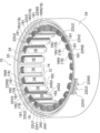
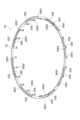
- FIG. 1 is a perspective view showing a stator according to a first embodiment
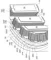
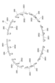
- FIG. FIG. 4 is a perspective view showing a state of the stator according to the first embodiment before the sealing resin is molded
- FIG. 3 is an enlarged perspective view showing an enlarged part of the configuration shown in FIG. 2
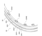
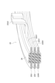
- FIG. 3 is a perspective view showing part of a first busbar unit included in the stator according to the first embodiment
- FIG. 5 is a perspective view of a portion of the first busbar unit viewed from a direction different from that of FIG. 4
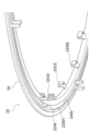
- FIG. 4 is a perspective cross-sectional view showing a state in which a part of the first busbar unit is cut
- FIG. 4 is a perspective view showing a second busbar unit included in the stator according to the first embodiment
- FIG. 8 is a perspective view showing a state in which illustration of insulating resin is omitted in the configuration shown in FIG. 7;
- FIG. 8 is a perspective cross-sectional view showing a state in which a part of a first busbar unit included in the stator according to the second embodiment is cut;
- FIG. 10 A stator 10 according to a first embodiment of the present disclosure will be described below with reference to FIGS. 1 to 8.
- FIG. 1 the scale of drawing is changed suitably.
- some reference numerals may be omitted to make the drawings easier to see.
- the stator 10 includes a stator core 12, a plurality of (here, 24) coils 18, an insulator 19, a first busbar unit 20, and a second busbar. It is an armature (stator) including a unit 26 and a sealing resin 32 .
- the stator core 12 , the plurality of coils 18 , the insulator 19 , the first busbar unit 20 , the second busbar unit 26 and the sealing resin 32 are housed inside a cylindrical case 34 .
- a rotor (not shown) is arranged inside the stator 10 to constitute an inner rotor type motor (rotary electric machine).
- This motor is, for example, a three-phase motor, and is a resin-molded motor in which a stator core 12 , a plurality of coils 18 , an insulator 19 , a first busbar unit 20 and a second busbar unit 26 are sealed with sealing resin 32 .
- the stator core 12 is constructed by laminating a plurality of iron core pieces made of electromagnetic steel sheets.
- This stator core 12 is formed in an annular shape and has a yoke 14 and a plurality of (here, 24) teeth 16 .
- the stator core 12 may be divided into a plurality of parts in the circumferential direction.
- the yoke 14 has a cylindrical shape.
- the plurality of teeth 16 are formed to protrude radially inward of the stator core 12 from the inner peripheral surface of the yoke 14 .
- a plurality of teeth 16 are formed side by side at regular intervals in the circumferential direction of the stator core 12 , and slots (reference numerals omitted) are formed between the plurality of teeth 16 .
- the stator 10 is fitted inside the case 34 .
- the number of poles and the number of slots of the stator 10 shown in FIG. 2 are merely examples, and are not limited to these.
- the plurality of coils 18 are spirally wound around the plurality of teeth 16 respectively.
- An insulator 19 is interposed between each coil 18 and each tooth 16 .
- an insulating material such as insulating paper or varnish may be interposed between each coil 18 and each tooth 16.
- FIG. Each coil 18 is configured such that a wire made of, for example, copper, aluminum, silver, or an alloy wire thereof is coated with an insulator such as enamel.
- this element wire is a round wire here, it may be a rectangular wire, a hexagonal wire, or the like.
- the coil 18 When viewed from the radial direction of the stator core 12 , the coil 18 is wound in a substantially elongated rectangular shape whose longitudinal direction is the axial direction of the stator core 12 .
- the coil 18 has one end 181 at the start of winding and the other end 182 at the end of winding, both of which are arranged on the root side of the teeth 16 .
- One end 181 extends to one side of stator core 12 in the axial direction, and the other end 182 extends to the other side of stator core 12 in the axial direction.
- the plurality of coils 18 includes a plurality (eight in this case) of U-phase coils 18U, a plurality of (eight in this case) of V-phase coils 18V, and a plurality of (eight in this case) of W-phase coils 18W. ing.
- a U-phase coil 18U, a V-phase coil 18V, and a W-phase coil 18W are sequentially arranged along the circumferential direction of the stator core 12 .
- the U-phase coils 18U, the V-phase coils 18V, and the W-phase coils 18W are mounted on the teeth 16 of the stator core 12 at intervals in the circumferential direction of the stator core 12, respectively.
- Adjacent in-phase coils 18 (same phase among U-phase, V-phase, and W-phase) are electrically connected to each other by first bus bar units 20 .
- the first busbar unit 20 is arranged adjacent to the stator core 12 on one side in the axial direction.
- the first busbar unit 20 includes a U-phase busbar 22U, a V-phase busbar 22V, a W-phase busbar 22W, and a first insulating resin 24 .
- the U-phase busbar 22U, the V-phase busbar 22V, and the W-phase busbar 22W correspond to the "busbar" in the present disclosure
- the first insulating resin 24 corresponds to the "insulating resin" in the present disclosure.
- the U-phase busbar 22U, the V-phase busbar 22V, and the W-phase busbar 22W are, for example, manufactured by press-molding a metal plate.
- the U-phase busbar 22U, the V-phase busbar 22V, and the W-phase busbar 22W respectively include first extending portions 22U1, 22V1, and 22W1 extending annularly along the yoke 14 in the circumferential direction of the stator core 12, and first extending portions 22U1, 22V1, and 22W1. It has a plurality of first joint portions 22U2, 22V2 and 22W2 extending from the portions 22U1, 22V1 and 22W1 to the root side of each tooth 16. As shown in FIG.
- the first extensions 22U1, 22V1, 22W1 correspond to the "extensions” in the present disclosure
- the first joints 22U2, 22V2, 22W2 correspond to the "joints” in the present disclosure
- the U-phase bus bar 22U, the V-phase bus bar 22V, and the W-phase bus bar 22W have a U-phase terminal portion 22U3 and a V-phase terminal portion extending radially outward of the stator core 12 from the first extension portions 22U1, 22V1, and 22W1. 22V3 and a W-phase terminal portion 22W3 (see FIGS. 1 and 2).
- the U-phase terminal portion 22U3, the V-phase terminal portion 22V3, and the W-phase terminal portion 22W3 may be configured to extend outward in the axial direction of the stator core 12 from the first extension portions 22U1, 22V1, and 22W1.
- First extension portion 22U1 of U-phase bus bar 22U, first extension portion 22V1 of V-phase bus bar 22V, and first extension portion 221W1 of W-phase bus bar 22W are arranged concentrically with stator core 12. .
- the first extending portions 22U1, 22V1, and 22W1 are plate-shaped with the axial direction of the stator core 12 as the plate thickness direction.
- the first extension portion 22U1 is arranged radially inward of the stator core 12 with respect to the first extension portion 22V1, and the first extension portion 22W1 and the first extension portion 22U1 It is arranged on the other axial side (the stator core 12 side) of the stator core 12 with respect to the first extension portion 22V1.
- the first extension portion 22U1 is displaced from the first extension portion 22V1 to one side in the axial direction of the stator core 12 .
- the first extending portions 22U1, 22V1, 22W1 are arranged in a region overlapping the yoke 14 when viewed from the axial direction of the stator core 12. As shown in FIG. Note that the above-described positional relationship among the first extension portions 22U1, 22V1, and 22W1 is merely an example.
- the first extending portions 22U1, 22V1, and 22W1 are not all around in the circumferential direction, but only partly, and there may be cases where the U-phase busbar 22U, the V-phase busbar 22V, and the W-phase busbar 22W do not overlap in the axial direction. .
- the U-phase busbar 22U, the V-phase busbar 22V, and the W-phase busbar 22W are integrated with the insulating resin 24, but each phase may be individually integrated with the insulating resin.
- the first extension portions 22U1, 22V1, and 22W1 are stacked in the plate thickness direction, but the first extension portions 22U1, 22V1, and 22W1 stand (the plate thickness direction faces the radial direction). can be configured).
- the first joint portions 22U2, 22V2, 22W2 extend from the first extension portions 22U1, 22V1, 22W1 to the radially inner side of the stator core 12 and to one side in the axial direction of the stator core 12. Located near the root. A first insertion portion (reference numerals omitted) is formed at each distal end portion of the first joint portions 22U2, 22V2, and 22W2. Each first insertion portion has a U shape with one side in the circumferential direction of the stator core 12 open when viewed from the axial direction of the stator core 12 . One end portion 181 of each coil 18 is inserted inside each first insertion portion, and each first insertion portion and one end portion 181 of each coil 18 are joined by means such as welding. It should be noted that a configuration in which the first inserting portion is not formed at each distal end portion of the first joint portions 22U2, 22V2, and 22W2 may be employed.
- the first insulating resin 24 is made of insulating resin and is formed in a ring shape.
- the first insulating resin 24 is fitted inside the case 34 .
- First extension portions 22U1, 22V1, 22W1 of the U-phase busbar 22U, the V-phase busbar 22V, and the W-phase busbar 22W are embedded in the first insulating resin 24 described above.
- the first extending portions 22U1, 22V1, 22W1 are embedded in the first insulating resin 24 by insert molding, for example, and the first insulating resin 24 is molded integrally with the first extending portions 22U1, 22V1, 22W1. It is
- the first insulating resin 24 has three openings 24U through which the first extending portions 22U1, 22V1, and 22W1 are partially exposed to the outside of the first insulating resin 24; 24V and 24W are formed.
- the three openings 24U, 24V, and 24W are formed in an annular shape concentric with the first insulating resin 24, for example.
- Two of the three openings 24U, 24V, 24W are formed on one surface of the first insulating resin 24 in the axial direction (the surface opposite to the stator core 12).
- One opening 24W of the openings 24U, 24V, and 24W is formed on the surface of the first insulating resin 24 on the other side in the axial direction (the surface on the stator core 12 side).
- the two openings 24U and 24V are arranged concentrically in the radial direction of the stator core 12, and the opening 24U is located on one side of the stator core 12 in the axial direction (opposite to the stator core 12) with respect to the first extending portion 22U1. side), and the surface of the first extension portion 22U1 on one side in the plate thickness direction is exposed to one side of the stator core 12 in the axial direction.
- the opening 24V is arranged on one side in the axial direction of the stator core 12 with respect to the first extending portion 22V1. exposing.
- the one opening 24W is arranged on the other side in the axial direction of the stator core 12 (the stator core 12 side) with respect to the first extending portion 22W1. It is exposed to the other side of the stator core 12 in the axial direction.
- the arrangement of the three openings 24U, 24V, and 24W can be appropriately changed according to the arrangement of the first extensions 22U1, 22V1, and 22W1. Further, in the present embodiment, the three openings 24U, 24V, 24W are formed in an annular shape. good.
- the second busbar unit 26 is arranged adjacent to the other side of the stator core 12 .
- the second busbar unit 26 is composed of a second busbar 28 and a second insulating resin 30 .
- the second busbar 28 corresponds to the "busbar" in the present disclosure
- the second insulating resin 30 corresponds to the "insulating resin" in the present disclosure.
- the first busbar unit 20 and the second busbar unit 26 are separately arranged on both sides of the stator core 12 in the axial direction in the present embodiment, they may be arranged together on one side. Also, not all busbars need to be integrated, and one or more busbar units may be used.
- the second busbar 28 is, for example, composed of a plurality of (here, eight) busbar divisions 28S.
- the plurality of busbar divisions 28S are arranged side by side at regular intervals in the circumferential direction of the stator core 12 .
- Each of the plurality of busbar divisions 28S includes a second extending portion 28S1 extending in an arc shape in the circumferential direction of the stator core 12 along the yoke 14 and extending from the second extending portion 28S1 to the tip side of each tooth 16. and a plurality of (here, three) second joint portions 28S2.
- the second extension portion 28S1 corresponds to the "extension portion" in the present disclosure
- the second joint portion 28S2 corresponds to the "joint portion" in the present disclosure.
- the second extending portion 28S1 has a plate-like shape curved in an arc concentric with the stator core 12 with the plate thickness direction being the axial direction of the stator core 12 .
- the plurality of second joint portions 28S2 extend from the second extending portion 28S1 to the radially inner side of the stator core 12 and to the other axial direction side of the stator core 12, and each tip portion is arranged near the root of each tooth 16.
- a second insertion portion (not shown) is formed at the tip of each second joint portion 28S2.
- Each second insertion portion has a U shape with one side in the circumferential direction of the stator core 12 open when viewed from the axial direction of the stator core 12 .
- each coil 18 is inserted inside each second insertion portion, and each second insertion portion and the other end 182 of each coil 18 are joined by means such as welding.
- the second insertion portion is not formed at the distal end portion of each second joint portion 28S2 may be employed.
- the second busbar 28 may be integrally formed without being divided into a plurality of busbar divisions 28S.
- the second bus bar 28 is divided into a plurality of parts depending on the motor specifications, but depending on the motor specifications, the second bus bar may not be divided and may be integrally formed.
- the second insulating resin 30 is made of insulating resin and is formed in a ring shape.
- the second insulating resin 30 is fitted inside the case 34 .
- the second extending portions 28S1 of the plurality of busbar divisions 28S are embedded in the second insulating resin 30. As shown in FIG.
- the second extending portion 28S1 is embedded in the second insulating resin 30 by insert molding, for example, and the second insulating resin 30 is molded integrally with the plurality of second extending portions 28S1.
- the second insulating resin 30 is formed with a plurality of (here, eight) openings 30S partially exposing the second extending portions 28S1 to the outside of the second insulating resin 30.
- the plurality of openings 30S are formed on the surface of the second insulating resin 30 on the other side in the axial direction (the surface on the side opposite to the stator core 12).
- the plurality of openings 30 ⁇ /b>S are formed in an arcuate shape concentric with the second insulating resin 30 and are arranged side by side at equal intervals in the circumferential direction of the stator core 12 .
- the plurality of openings 30S are arranged on the other side in the axial direction of the stator core 12 (on the side opposite to the stator core 12) with respect to the second extensions 28S1 of the plurality of second bus bars 28. is exposed to the other side of the stator core 12 in the axial direction.
- the sealing resin 32 is a mold resin sealing the stator core 12, the plurality of coils 18, the insulator 19, the first busbar unit 20 and the second busbar unit 26.
- the sealing resin 32 is a thermosetting resin such as epoxy resin or a thermoplastic resin kneaded with non-magnetic powder as a filler, and has thermal conductivity and insulating properties. .
- the sealing resin 32 has higher thermal conductivity than the first insulating resin 24 and the second insulating resin 30 .
- the sealing resin 32 is molded by, for example, cast molding or transfer molding, and has a cylindrical outer shape. Both axial end faces of the sealing resin 32 are arranged flush with the axial end faces of the case 34 .
- the stator core 12 , the plurality of coils 18 , the insulator 19 , the first busbar unit 20 and the second busbar unit 26 are embedded in the sealing resin 32 .
- a portion of the sealing resin 32 enters the three openings 24U, 24V, and 24W formed in the first insulating resin 24 of the first busbar unit 20 .
- Part of the sealing resin 32 is in close contact with the first extending portions 22U1, 22V1, 22W1 of the U-phase busbar 22U, the V-phase busbar 22V, and the W-phase busbar 22W.
- a portion of the sealing resin 32 enters the plurality of openings 30S formed in the second insulating resin 30 of the second busbar unit 26 .
- a portion of the sealing resin 32 is in close contact with the second extending portions 28S1 of the plurality of busbar divisions 28S.
- the U-phase terminal portion 22U3, the V-phase terminal portion 22V3, and the W-phase terminal portion 22W3 of the U-phase busbar 22U, the V-phase busbar 22V, and the W-phase busbar 22W are connected to a three-phase power supply.
- the stator 10 configured as described above functions as a stator of a three-phase motor.
- this three-phase motor is provided with a flow path for a cooling medium such as oil cooling by a fluid such as Automatic Transmission Fluid, forced air cooling by blowing air, or forced water cooling using a water jacket.
- a cooling medium such as oil cooling by a fluid such as Automatic Transmission Fluid, forced air cooling by blowing air, or forced water cooling using a water jacket.
- the coils 18 are wound around the plurality of teeth 16 of the stator core 12 .
- One end portion 181 of each coil 18 is connected to first joint portions 22U2, 22V2, 22W2 of U-phase busbar 22U, V-phase busbar 22V, and W-phase busbar 22W, which are arranged adjacent to the stator core 12 on one side in the axial direction.
- U-phase busbar 22U, V-phase busbar 22V and W-phase busbar 22W have first extending portions 22U1, 22V1 and 22W1 extending in the circumferential direction of the stator core 12 .
- These first extending portions 22U1, 22V1, 22W1 are partially exposed from the first insulating resin 24 integrally formed with the U-phase busbar 22U, the V-phase busbar 22V, and the W-phase busbar 22W.
- each coil 18 is joined to a second joint 28S2 of a plurality of busbar divisions 28S arranged adjacent to the stator core 12 on the other side in the axial direction.
- These busbar divisions 28S have second extending portions 28S2 extending in the circumferential direction of the stator core 12 along the yoke 14 of the stator core 12. As shown in FIG. These second extending portions 28S1 are partially exposed from the second insulating resin 30 integrally molded with the plurality of busbar divisions 28S.
- the portions of the first extending portions 22U1, 22V1, 22W1 exposed from the first insulating resin 24 are sealed with a sealing resin 32 made of a resin having a higher thermal conductivity than the first insulating resin 24.
- the portion of the second extending portion 28S1 exposed from the second insulating resin 30 is sealed with the sealing resin 32 described above. Since the heat of each of the bus bars 22U, 22V, 22W, and 28S can be radiated through the sealing resin 32, even if the thermal conductivity of the first insulating resin 24 and the second insulating resin 30 is low, each of the bus bars 22U, 22V, 22W, and 28S can 22V, 22W, and 28S heat dissipation can be improved. As a result, it is possible to improve the performance of the motor while ensuring the moldability of the first insulating resin 24 and the second insulating resin 30 and suppressing an increase in the manufacturing cost.
- part of the first extending portions 22U1, 22V1, 22W1 of the U-phase busbar 22U, the V-phase busbar 22V, and the W-phase busbar 22W extends from the first insulating resin 24 in the axial direction of the stator core 12. Exposed. Similarly, a portion of the second extending portions 28S1 of the plurality of busbar divisions 28S are exposed from the second insulating resin 30 in the axial direction of the stator core 12. As shown in FIG. The exposed portions of the first extending portions 22U1, 22V1, 22W1 and the second extending portion 28S1 are sealed with a sealing resin 32. As shown in FIG. As a result, for example, while suppressing an increase in radial space of the stator core 12, the heat dissipation of each of the bus bars 22U, 22V, 22W, and 28S can be enhanced.
- the portions of the extension portions 22U1, 22V1, 22W1 and 28S2 exposed from the insulating resins 24 and 30 are the plate thicknesses of the extension portion extension portions 22U1, 22V1, 22W1 and 28S2. Since it is the surface on one side in the direction, the area of the exposed portion can be increased.
- the portions of the first extension portions 22U1, 22V1, 22W1 exposed from the first insulating resin 24 and the portions of the second extension portions 28S1 exposed from the second insulating resin 30 are sealed.
- the stator core 12 , the plurality of coils 18 , the insulator 19 , the first busbar unit 20 and the second busbar unit 26 are sealed by the sealing resin 32 that has stopped.
- the exposed portions of the first extending portions 22U1, 22V1, 22W1 and the second extending portion 28S1 from the first insulating resin 24 and the second insulating resin 30 are sealed with the sealing resin 32 of the resin-molded motor. It is This eliminates the need for a dedicated sealing resin for improving the heat dissipation of each bus bar 22U, 22V, 22W, 28S.
- the cooling medium flow path is provided near the exposed portions of the extending portions 22U1, 22V1, 22W1, and 28S2 from the insulating resins 24 and 30, insulation with low thermal conductivity is provided. Compared to the case where a cooling medium is provided in the resins 24 and 30, heat dissipation can be further enhanced by cooling via a sealing resin having high thermal conductivity.
- the second embodiment is the same as the first embodiment except that the configuration of the first busbar unit 20 shown in FIG. 9 is different from the configuration of the first busbar unit 20 in the first embodiment.
- the first extending portions 22U1, 22V1, and 22W1 of the U-phase busbar 22U, the V-phase busbar 22V, and the W-phase busbar 22W are arranged in the axial direction of the stator core 12 at intervals.
- These first extending portions 22 U 1 , 22 V 1 , 22 W 1 are embedded in the first insulating resin 24 at intermediate portions in the radial direction of the stator core 12 .
- a plurality of through holes are formed side by side in the circumferential direction of the stator core 12 in the intermediate portions of the first extending portions 22U1, 22V1, 22W1. is entering.
- the through holes are necessary for fixing and integrating the U-phase busbar 22U, the V-phase busbar 22V, and the W-phase busbar 22W, and are not necessarily required if they are integrated in another structure. For example, if only one of the first extending portions 22U1, 22V1, and 22W1 is exposed in the radial direction, and the insulating resin is connected to the other side, the through hole is not necessary.
- the first extending portions 22U1, 22V1, 22W1 of the U-phase busbar 22U, the V-phase busbar 22V, and the W-phase busbar 22W extend from the first insulating resin 24 to the stator core. 12 are exposed in the axial and radial directions, and the exposed portions are sealed with a sealing resin 32 (not shown in FIG. 9).
- a sealing resin 32 not shown in FIG. 9
- the shape of the exposed portions of the bus bars 22U, 22V, and 22W can be freely designed, and the heat dissipation of the bus bars 22U, 22V, and 22W can be enhanced.
- the radially opposite side portions of the first extending portions 22U1, 22V1, and 22W1 protrude from the first insulating resin 24, but only the radially one side portion may protrude.
- the extension portions 22U1, 22V1, and 22W1 may alternately protrude radially inward and outward.
- the U-phase busbar 22U, the V-phase busbar 22V, and the W-phase busbar 22W are formed in a ring shape, but the present invention is not limited to this.
- the U-phase busbar 22U, the V-phase busbar 22V, and the W-phase busbar 22W may be formed in a C shape.
Landscapes
- Engineering & Computer Science (AREA)
- Power Engineering (AREA)
- Insulation, Fastening Of Motor, Generator Windings (AREA)
- Iron Core Of Rotating Electric Machines (AREA)
Abstract
Description
以下、図1~図8を参照して本開示の第1実施形態に係るステータ10について説明する。なお、各図においては図面の縮尺を適宜変更している。また、各図においては図面を見易くする関係から一部の符号を省略している場合がある。
に接続されている。
部が形成されない構成にしてもよい。
三相の電源に接続される。これにより、上記構成のステータ10が、三相モータのステータとして機能する。図示は省略するが、この三相モータでは、例えばAutomatic Transmission Fluid等の流体による油冷、送風による強制空冷、又はウォータージャケットを用いる強制水冷等の冷却媒体の流路が設けられる。この流路は、各延在部22U1、22V1、22W1、28S2の各絶縁樹脂24、30からの露出部分の付近に設けられる。
次に、本実施形態の作用及び効果について説明する。
ける第1絶縁樹脂24からの露出部分と、第2延在部28S1における第2絶縁樹脂30からの露出部分とを封止した封止樹脂32によって、ステータコア12、複数のコイル18、インシュレータ19、第1バスバーユニット20及び第2バスバーユニット26が封止されている。このように、樹脂モールドモータの封止樹脂32によって、第1絶縁樹脂24及び第2絶縁樹脂30からの第1延在部22U1、22V1、22W1及び第2延在部28S1の露出部分が封止されている。これにより、各バスバー22U、22V、22W、28Sの放熱性を高めるための専用の封止樹脂が不要になる。
次に、図9を参照して本開示の第2実施形態について説明する。なお、第1実施形態と基本的に同様の構成及び作用については、第1実施形態と同符号を付与しその説明を省略する。
Claims (6)
- ヨーク及び複数のティースを有するステータコアと、
前記複数のティースにそれぞれ巻回される複数のコイルと、
前記ステータコアに隣接して配置され、前記コイルの端部が接合される接合部及び前記ステータコアの周方向に延在する延在部を有するバスバーと、
前記延在部を部分的に露出させた状態で前記バスバーと一体に成形された絶縁樹脂と、
前記絶縁樹脂よりも熱伝導率が高い樹脂からなり、少なくとも前記絶縁樹脂からの前記延在部の露出部分を封止した封止樹脂と、
を備えるステータ。 - 前記延在部の一部は、前記絶縁樹脂から前記ステータコアの軸線方向に露出している請求項1に記載のステータ。
- 前記延在部の前記絶縁樹脂からの露出部分は、前記延在部の板厚方向一方側の面である請求項2に記載のステータ。
- 前記延在部の一部は、前記絶縁樹脂から前記ステータコアの径方向に露出している請求項1~請求項3の何れか1項に記載のステータ。
- 前記ステータコア、前記複数のコイル及び前記絶縁樹脂が、前記封止樹脂によって封止されている請求項1~請求項4の何れか1項に記載のステータ。
- 前記前記延在部の前記絶縁樹脂からの露出部分の付近に冷却媒体の流路が設けられている請求項1~請求項5の何れか1項に記載のステータ。
Priority Applications (4)
| Application Number | Priority Date | Filing Date | Title |
|---|---|---|---|
| JP2023521769A JP7358681B1 (ja) | 2021-12-27 | 2022-12-22 | ステータ |
| EP22915921.5A EP4425760A4 (en) | 2021-12-27 | 2022-12-22 | STATOR |
| CN202280080492.2A CN118355588A (zh) | 2021-12-27 | 2022-12-22 | 定子 |
| US18/719,232 US20250132625A1 (en) | 2021-12-27 | 2022-12-22 | Stator |
Applications Claiming Priority (2)
| Application Number | Priority Date | Filing Date | Title |
|---|---|---|---|
| JP2021-213133 | 2021-12-27 | ||
| JP2021213133 | 2021-12-27 |
Publications (1)
| Publication Number | Publication Date |
|---|---|
| WO2023127698A1 true WO2023127698A1 (ja) | 2023-07-06 |
Family
ID=86999131
Family Applications (1)
| Application Number | Title | Priority Date | Filing Date |
|---|---|---|---|
| PCT/JP2022/047461 Ceased WO2023127698A1 (ja) | 2021-12-27 | 2022-12-22 | ステータ |
Country Status (5)
| Country | Link |
|---|---|
| US (1) | US20250132625A1 (ja) |
| EP (1) | EP4425760A4 (ja) |
| JP (1) | JP7358681B1 (ja) |
| CN (1) | CN118355588A (ja) |
| WO (1) | WO2023127698A1 (ja) |
Families Citing this family (1)
| Publication number | Priority date | Publication date | Assignee | Title |
|---|---|---|---|---|
| KR102828982B1 (ko) * | 2023-12-11 | 2025-07-03 | 주식회사 신라공업 | 사출방식 모터 기반 액추에이터용 스테이터 절연구성 및 그 절연방법 |
Citations (5)
| Publication number | Priority date | Publication date | Assignee | Title |
|---|---|---|---|---|
| JP2010200400A (ja) * | 2009-02-23 | 2010-09-09 | Nippon Densan Corp | ステータ、バスバーユニット、モータ、及びパワーステアリング装置 |
| WO2015151214A1 (ja) * | 2014-03-31 | 2015-10-08 | 日産自動車株式会社 | ステータアッシ |
| JP2016032316A (ja) * | 2014-07-28 | 2016-03-07 | 株式会社明電舎 | 回転機 |
| JP2018019511A (ja) | 2016-07-28 | 2018-02-01 | 株式会社ミツバ | バスバーユニット及びスイッチドリラクタンスモータ |
| WO2020100253A1 (ja) * | 2018-11-15 | 2020-05-22 | 三菱電機株式会社 | 電動機及び空気調和機 |
Family Cites Families (2)
| Publication number | Priority date | Publication date | Assignee | Title |
|---|---|---|---|---|
| WO2014011783A1 (en) * | 2012-07-11 | 2014-01-16 | Remy Technologies, Llc | Interlocking coil isolators for resin retention in a segmented stator assembly |
| US10630127B1 (en) * | 2017-01-06 | 2020-04-21 | Apple Inc. | Electric motor with bar wound stator and end turn cooling |
-
2022
- 2022-12-22 US US18/719,232 patent/US20250132625A1/en active Pending
- 2022-12-22 EP EP22915921.5A patent/EP4425760A4/en active Pending
- 2022-12-22 JP JP2023521769A patent/JP7358681B1/ja active Active
- 2022-12-22 CN CN202280080492.2A patent/CN118355588A/zh active Pending
- 2022-12-22 WO PCT/JP2022/047461 patent/WO2023127698A1/ja not_active Ceased
Patent Citations (5)
| Publication number | Priority date | Publication date | Assignee | Title |
|---|---|---|---|---|
| JP2010200400A (ja) * | 2009-02-23 | 2010-09-09 | Nippon Densan Corp | ステータ、バスバーユニット、モータ、及びパワーステアリング装置 |
| WO2015151214A1 (ja) * | 2014-03-31 | 2015-10-08 | 日産自動車株式会社 | ステータアッシ |
| JP2016032316A (ja) * | 2014-07-28 | 2016-03-07 | 株式会社明電舎 | 回転機 |
| JP2018019511A (ja) | 2016-07-28 | 2018-02-01 | 株式会社ミツバ | バスバーユニット及びスイッチドリラクタンスモータ |
| WO2020100253A1 (ja) * | 2018-11-15 | 2020-05-22 | 三菱電機株式会社 | 電動機及び空気調和機 |
Non-Patent Citations (1)
| Title |
|---|
| See also references of EP4425760A4 |
Also Published As
| Publication number | Publication date |
|---|---|
| EP4425760A1 (en) | 2024-09-04 |
| EP4425760A4 (en) | 2025-05-07 |
| JPWO2023127698A1 (ja) | 2023-07-06 |
| JP7358681B1 (ja) | 2023-10-10 |
| CN118355588A (zh) | 2024-07-16 |
| US20250132625A1 (en) | 2025-04-24 |
Similar Documents
| Publication | Publication Date | Title |
|---|---|---|
| JP7344807B2 (ja) | コイルボビン、分布巻ラジアルギャップ型回転電機の固定子コア及び分布巻ラジアルギャップ型回転電機 | |
| JP6727457B1 (ja) | ステータおよび電動機 | |
| JP5267091B2 (ja) | 回転電機用ステータ | |
| CN102369651B (zh) | 电机的定子 | |
| US9893594B2 (en) | Armature of rotating electrical machine and method for manufacturing same | |
| WO2014192350A1 (ja) | 回転電機およびその製造方法 | |
| CN104335456A (zh) | 定子以及定子的制造方法 | |
| JP5292973B2 (ja) | 回転電機の固定子及び回転電機 | |
| WO2018147392A1 (ja) | 回転電機 | |
| CN111628592B (zh) | 电能与机械能的转换器 | |
| CN103548242A (zh) | 用于制造尤其是交流电机的电机的定子绕组的方法 | |
| JP7358681B1 (ja) | ステータ | |
| CN111628594A (zh) | 电能与机械能的转换器 | |
| CN115411862B (zh) | 定子 | |
| JP2009131054A (ja) | バスバー用ホルダー及びバスバーユニット、ステータ、モータ | |
| US20240235311A1 (en) | Armature and motor | |
| WO2021111790A1 (ja) | 電機子分割体、電機子、回転電機及び電機子分割体の製造方法 | |
| JP2016127681A (ja) | 回転電機のステータ | |
| JP7216254B2 (ja) | ステータ | |
| JP2024149938A (ja) | 回転電機 | |
| JP7188370B2 (ja) | 電気エネルギーと力学的エネルギーとの変換器 | |
| JP7150171B2 (ja) | 回転電機の固定子、端子台及び回転電機 | |
| JP7205454B2 (ja) | ステータ、ステータアッセンブリ、電気エネルギーと力学的エネルギーとの変換器 | |
| JP2019126178A (ja) | モーターステーター | |
| CN113572279A (zh) | 电机定子组件、电机及电动工具 |
Legal Events
| Date | Code | Title | Description |
|---|---|---|---|
| WWE | Wipo information: entry into national phase |
Ref document number: 2023521769 Country of ref document: JP |
|
| 121 | Ep: the epo has been informed by wipo that ep was designated in this application |
Ref document number: 22915921 Country of ref document: EP Kind code of ref document: A1 |
|
| WWE | Wipo information: entry into national phase |
Ref document number: 2022915921 Country of ref document: EP |
|
| ENP | Entry into the national phase |
Ref document number: 2022915921 Country of ref document: EP Effective date: 20240528 |
|
| WWE | Wipo information: entry into national phase |
Ref document number: 202280080492.2 Country of ref document: CN |
|
| WWE | Wipo information: entry into national phase |
Ref document number: 18719232 Country of ref document: US |
|
| NENP | Non-entry into the national phase |
Ref country code: DE |
|
| WWP | Wipo information: published in national office |
Ref document number: 18719232 Country of ref document: US |