WO2023140141A1 - 端子及びコネクタ - Google Patents
端子及びコネクタ Download PDFInfo
- Publication number
- WO2023140141A1 WO2023140141A1 PCT/JP2023/000280 JP2023000280W WO2023140141A1 WO 2023140141 A1 WO2023140141 A1 WO 2023140141A1 JP 2023000280 W JP2023000280 W JP 2023000280W WO 2023140141 A1 WO2023140141 A1 WO 2023140141A1
- Authority
- WO
- WIPO (PCT)
- Prior art keywords
- terminal
- wall
- bottom wall
- box
- box portion
- Prior art date
- Legal status (The legal status is an assumption and is not a legal conclusion. Google has not performed a legal analysis and makes no representation as to the accuracy of the status listed.)
- Ceased
Links
Images



Classifications
-
- H—ELECTRICITY
- H01—ELECTRIC ELEMENTS
- H01R—ELECTRICALLY-CONDUCTIVE CONNECTIONS; STRUCTURAL ASSOCIATIONS OF A PLURALITY OF MUTUALLY-INSULATED ELECTRICAL CONNECTING ELEMENTS; COUPLING DEVICES; CURRENT COLLECTORS
- H01R43/00—Apparatus or processes specially adapted for manufacturing, assembling, maintaining, or repairing of line connectors or current collectors or for joining electric conductors
- H01R43/20—Apparatus or processes specially adapted for manufacturing, assembling, maintaining, or repairing of line connectors or current collectors or for joining electric conductors for assembling or disassembling contact members with insulating base, case or sleeve
-
- H—ELECTRICITY
- H01—ELECTRIC ELEMENTS
- H01R—ELECTRICALLY-CONDUCTIVE CONNECTIONS; STRUCTURAL ASSOCIATIONS OF A PLURALITY OF MUTUALLY-INSULATED ELECTRICAL CONNECTING ELEMENTS; COUPLING DEVICES; CURRENT COLLECTORS
- H01R13/00—Details of coupling devices of the kinds covered by groups H01R12/70 or H01R24/00 - H01R33/00
- H01R13/46—Bases; Cases
- H01R13/52—Dustproof, splashproof, drip-proof, waterproof, or flameproof cases
- H01R13/5205—Sealing means between cable and housing, e.g. grommet
- H01R13/5208—Sealing means between cable and housing, e.g. grommet having at least two cable receiving openings
-
- H—ELECTRICITY
- H01—ELECTRIC ELEMENTS
- H01R—ELECTRICALLY-CONDUCTIVE CONNECTIONS; STRUCTURAL ASSOCIATIONS OF A PLURALITY OF MUTUALLY-INSULATED ELECTRICAL CONNECTING ELEMENTS; COUPLING DEVICES; CURRENT COLLECTORS
- H01R43/00—Apparatus or processes specially adapted for manufacturing, assembling, maintaining, or repairing of line connectors or current collectors or for joining electric conductors
- H01R43/005—Apparatus or processes specially adapted for manufacturing, assembling, maintaining, or repairing of line connectors or current collectors or for joining electric conductors for making dustproof, splashproof, drip-proof, waterproof, or flameproof connection, coupling, or casing
-
- H—ELECTRICITY
- H01—ELECTRIC ELEMENTS
- H01R—ELECTRICALLY-CONDUCTIVE CONNECTIONS; STRUCTURAL ASSOCIATIONS OF A PLURALITY OF MUTUALLY-INSULATED ELECTRICAL CONNECTING ELEMENTS; COUPLING DEVICES; CURRENT COLLECTORS
- H01R13/00—Details of coupling devices of the kinds covered by groups H01R12/70 or H01R24/00 - H01R33/00
- H01R13/40—Securing contact members in or to a base or case; Insulating of contact members
- H01R13/42—Securing in a demountable manner
- H01R13/436—Securing a plurality of contact members by one locking piece or operation
- H01R13/4361—Insertion of locking piece perpendicular to direction of contact insertion
-
- H—ELECTRICITY
- H01—ELECTRIC ELEMENTS
- H01R—ELECTRICALLY-CONDUCTIVE CONNECTIONS; STRUCTURAL ASSOCIATIONS OF A PLURALITY OF MUTUALLY-INSULATED ELECTRICAL CONNECTING ELEMENTS; COUPLING DEVICES; CURRENT COLLECTORS
- H01R4/00—Electrically-conductive connections between two or more conductive members in direct contact, i.e. touching one another; Means for effecting or maintaining such contact; Electrically-conductive connections having two or more spaced connecting locations for conductors and using contact members penetrating insulation
- H01R4/10—Electrically-conductive connections between two or more conductive members in direct contact, i.e. touching one another; Means for effecting or maintaining such contact; Electrically-conductive connections having two or more spaced connecting locations for conductors and using contact members penetrating insulation effected solely by twisting, wrapping, bending, crimping, or other permanent deformation
- H01R4/18—Electrically-conductive connections between two or more conductive members in direct contact, i.e. touching one another; Means for effecting or maintaining such contact; Electrically-conductive connections having two or more spaced connecting locations for conductors and using contact members penetrating insulation effected solely by twisting, wrapping, bending, crimping, or other permanent deformation by crimping
- H01R4/183—Electrically-conductive connections between two or more conductive members in direct contact, i.e. touching one another; Means for effecting or maintaining such contact; Electrically-conductive connections having two or more spaced connecting locations for conductors and using contact members penetrating insulation effected solely by twisting, wrapping, bending, crimping, or other permanent deformation by crimping for cylindrical elongated bodies, e.g. cables having circular cross-section
- H01R4/184—Electrically-conductive connections between two or more conductive members in direct contact, i.e. touching one another; Means for effecting or maintaining such contact; Electrically-conductive connections having two or more spaced connecting locations for conductors and using contact members penetrating insulation effected solely by twisting, wrapping, bending, crimping, or other permanent deformation by crimping for cylindrical elongated bodies, e.g. cables having circular cross-section comprising a U-shaped wire-receiving portion
- H01R4/185—Electrically-conductive connections between two or more conductive members in direct contact, i.e. touching one another; Means for effecting or maintaining such contact; Electrically-conductive connections having two or more spaced connecting locations for conductors and using contact members penetrating insulation effected solely by twisting, wrapping, bending, crimping, or other permanent deformation by crimping for cylindrical elongated bodies, e.g. cables having circular cross-section comprising a U-shaped wire-receiving portion combined with a U-shaped insulation-receiving portion
-
- H—ELECTRICITY
- H01—ELECTRIC ELEMENTS
- H01R—ELECTRICALLY-CONDUCTIVE CONNECTIONS; STRUCTURAL ASSOCIATIONS OF A PLURALITY OF MUTUALLY-INSULATED ELECTRICAL CONNECTING ELEMENTS; COUPLING DEVICES; CURRENT COLLECTORS
- H01R43/00—Apparatus or processes specially adapted for manufacturing, assembling, maintaining, or repairing of line connectors or current collectors or for joining electric conductors
- H01R43/16—Apparatus or processes specially adapted for manufacturing, assembling, maintaining, or repairing of line connectors or current collectors or for joining electric conductors for manufacturing contact members, e.g. by punching and by bending
Definitions
- the present disclosure relates to terminals and connectors.
- a terminal that does not easily damage the mat seal during insertion is known (Japanese Patent Laid-Open No. 2016-001579).
- a lance engaging portion and a locking portion having inclined portions are formed by bending, so that the broken surface of the metal plate does not come into contact with the mat seal. Further, when the terminal is pulled out from the mat seal and separated, the inclined portion of the locking portion comes into contact with the mat seal, so damage to the mat seal can be suppressed.
- the convex lance engaging portion and locking portion are formed by intricately bending the metal plate. For this reason, there is a risk that the number of man-hours required for molding will increase, or that the cost of raw materials and processing will increase.
- the present disclosure has been completed based on the circumstances as described above, and aims to provide a technique of suppressing damage to the mat seal during detachment with a simple structure.
- the present disclosure is a terminal that is inserted from the rear to the front into a seal hole of a mat seal provided in a housing and that is removed from the front to the rear, the terminal including a substantially box-shaped first box portion, the first box portion having a first bottom wall, a pair of first side walls rising from both ends of the first bottom wall, a first ceiling wall facing the first bottom wall, and a locking wall positioned at a rear end that is a tip in a detachment direction, and the first ceiling wall and the locking wall It is connected via a connecting portion curved from the detachment direction to the direction of the first bottom wall.
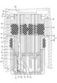
- FIG. 1 is an exploded perspective view of a female connector including terminals according to Embodiment 1.
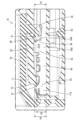
- FIG. FIG. 2 is a side cross-sectional view showing a state in which the terminals are held in their normal positions.
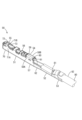
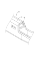
- FIG. 3 is a perspective view of the terminal viewed obliquely from above and behind. 4 is a partially enlarged view of FIG. 3.
- FIG. 5 is a partially enlarged view of FIG. 2.
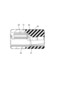
- FIG. FIG. 6 is a side cross-sectional view showing the terminal in contact with the seal hole during the detachment process.
- FIG. 7 is a perspective view showing a conventionally shaped terminal.
- FIG. 8 is a side cross-sectional view showing the terminal in contact with the seal hole in the process of detaching the conventionally-shaped terminal.
- the present disclosure is a terminal that is inserted from the rear to the front into a seal hole of a mat seal provided in a housing and that is removed from the front to the rear, and includes a substantially box-shaped first box portion, the first box portion having a first bottom wall, a pair of first side walls rising from both ends of the first bottom wall, a first ceiling wall facing the first bottom wall, and a locking wall positioned at a rear end that is a tip in a detachment direction, wherein the first ceiling wall and the locking wall are: It is connected via a connecting portion curved in the direction of the first bottom wall from the detachment direction.
- the connecting portion curved from the detachment direction toward the first bottom wall contacts the seal hole before the fractured surface. Since the seal hole is expanded by the connecting portion, contact with, for example, a fractured surface formed at the rear end of the first box portion can be avoided, and damage to the mat seal can be suppressed.
- the load When a load is applied to the terminal in the detachment direction, the load can be received by the plate surface of the locking wall. As a result, the load is distributed over the entire plate surface, and deformation of the terminal can be suppressed.
- At least one of the first side walls has an extension portion extending toward the rear, and the extension end of the extension portion overlaps the plate surface of the locking wall when viewed from the direction perpendicular to the detachment direction.
- the extension end can also receive the load in the detachment direction. As a result, the load is further distributed, and deformation of the terminal can be suppressed.
- the terminal includes a substantially box-shaped second box portion spaced forward from the first box portion.
- the second box portion has a second bottom wall, a pair of second side walls rising from both ends of the second bottom wall, and a second ceiling wall facing the second bottom wall.
- the second box portion passes through the seal hole expanded by the first box portion. Since the height of the second box portion is smaller than the height of the first box portion, the second box portion is less likely to get caught in the seal hole, and the terminal can be easily removed from the housing. Since the load on the terminal is reduced when it is detached, deformation of the second box portion can be suppressed.
- a connector of the present disclosure includes a terminal of the present disclosure and a housing having a cavity in which the terminal is accommodated.
- Embodiment 1 of the present disclosure will be described with reference to FIGS. 1 to 8.
- FIG. 1 An illustration of an example embodiment of the present disclosure.
- the connector according to this embodiment is constructed by assembling a plurality of terminals 50 to a housing 10. As shown in FIG. Note that the number of terminals 50 illustrated in FIG. 1 is one.
- the housing 10 is configured by assembling a housing body 11, a retainer 30, a seal ring 35, a mat seal 40, and a mat seal holder 45. As shown in FIG.
- the housing body 11 is constructed by assembling an inner housing 15 and an outer housing 20 .
- the front-rear direction refers to the side where the connector is mated with the mating connector.
- the diagonally lower left front side in FIG. 1 and the left side in FIGS. 2 and 3 are defined as the front.
- the vertical direction in FIGS. 1 to 3 is defined as upward and downward.
- the front is the direction in which the terminals 50 are inserted into the housing 10 .
- the rear is the direction in which the terminal 50 is detached from the housing 10 .
- the outer housing 20 is made of synthetic resin.
- the outer housing 20 has a terminal accommodating portion 21 and a cylindrical fitting portion 22 .
- the tubular fitting portion 22 protrudes forward from the rear end portion of the outer periphery of the terminal accommodating portion 21 so as to surround the terminal accommodating portion 21 .
- the inner housing 15 is made of synthetic resin and has a substantially rectangular block shape as a whole.
- the inner housing 15 has four engaging portions 18 extending rearward from the rear end surface.
- the housing body 11 is formed by bringing the inner housing 15 closer to the outer housing 20 from the front and engaging the engaging portion 18 with an engaged portion (not shown) provided on the outer wall of the terminal accommodating portion 21 .
- the inner housing 15 is provided with a plurality of cavities 16 penetrating therethrough in the front-rear direction.
- a lance 17 is provided on the inner surface of each cavity 16 so as to protrude forward in a cantilevered manner.
- a terminal 50 connected to an end of a cable 80 is inserted into each cavity 16 from behind. The terminal 50 is elastically locked to the lance 17 and retained in the cavity 16 to prevent it from coming off.
- the retainer 30 consists of a left and right synthetic resin retainer right piece 30A and a retainer left piece 30B.
- the combined retainer 30 has a cap shape with a rear opening.
- the retainer 30 has a substantially rectangular planar front wall 31 and a peripheral wall 32 protruding rearward from the peripheral edge of the front wall 31 .
- the front wall 31 is provided with a plurality of insertion holes 33 through which tabs of male terminals (not shown) attached to a mating connector can be inserted.
- the insertion holes 33 are provided at positions corresponding to the cavities 16 on a one-to-one basis when viewed from the front-rear direction.
- the right retainer piece 30A and the left retainer piece 30B each have a restricting portion 34 extending in the left-right direction.
- the front wall 31 is arranged to face the front surface of the housing body 11, and the peripheral wall 32 is arranged to cover the outer peripheral surface of the inner housing 15.
- the restricting portion 34 is inserted from the left and right toward the rear of the first box portion 54 of the terminal 50, which will be described later.
- the front surface of the restricting portion 34 is arranged at a position facing an engaging wall 61 of the terminal 50, which will be described later, and restricts the terminal 50 from being displaced rearward (withdrawal direction).
- the seal ring 35 is made of rubber. As shown in FIG. 1 , the seal ring 35 has a substantially rectangular annular shape and is fitted and held on the outer peripheral surface of the inner housing 15 . As shown in FIG. 2, the seal ring 35 is arranged in contact with a stepped surface 19 provided on the outer peripheral surface of the inner housing 15 from the front. When the connector is mated with a mating connector (not shown), the seal ring 35 is elastically sandwiched between the hood portion of the mating connector and the inner housing 15 to liquid-tightly seal the two connectors.
- a housing recess 23 is recessed in the rear surface of the outer housing 20 .
- the terminal accommodating portion 21 and the accommodating recess 23 are separated by the rear end portion of the terminal accommodating portion 21 .
- the mat seal 40 is made of rubber and, as shown in FIG. 1, has a plate-like shape with a substantially rectangular cross section and extends in a direction substantially perpendicular to the front-rear direction.
- the mat seal 40 is inserted into the housing recess 23 from the rear, and as shown in FIG.
- the mat seal 40 is provided with substantially circular seal holes 41 penetrating in the front-rear direction at positions corresponding to the cavities 16 on a one-to-one basis.
- a terminal 50 and a cable 80 connected to the terminal 50 are inserted into each seal hole 41 from behind. After the terminal 50 passes through the seal hole 41, the periphery of the cable 80 is liquid-tightly sealed.
- the mat seal holder 45 is made of synthetic resin and has a plate shape with a substantially rectangular cross section as shown in FIG.
- the mat seal holder 45 has holder holes 46 that open at positions corresponding to the seal holes 41 on a one-to-one basis.
- the terminal 50 is formed by, for example, bending after punching a conductive metal plate into a predetermined shape.
- the terminal 50 of this embodiment is a female terminal and has a shape elongated in the front-rear direction. As shown in FIG. 3, the terminal 50 has a main body portion 51 at its front portion and a wire barrel portion 52 and an insulation barrel portion 53 at its rear portion.
- the insulation barrel portion 53 is arranged behind the wire barrel portion 52 .
- the wire barrel portion 52 is crimped and connected to the conductor 81 (twisted wire or the like) exposed by removing the coating 82 at the front end portion of the cable 80 .
- the insulation barrel portion 53 is crimped and connected to the covering 82 at the front end of the cable 80 (the covering 82 located behind the exposed conductor 81).
- the body portion 51 has a first box portion 54 positioned at the rear end of the body portion 51, a second box portion 55 positioned at the front end of the body portion 51, and an intermediate portion 56 positioned between the first box portion 54 and the second box portion 55.
- the first box portion 54 has a first bottom wall 57 located on the lower side, a pair of first side walls 58A and 58B, a first ceiling wall 59 located on the upper side, a connection portion 60 extending downward from the rear starting from the rear end of the first ceiling wall 59, and a locking wall 61 connected to the tip of the connection portion 60.
- the first side walls 58A and 58B are collectively referred to as the first side wall 58.
- the first bottom wall 57 is a part of the lower wall of the main body 51 and extends in the front-rear direction and the left-right direction (width direction).
- the first bottom wall 57 is connected to the wire barrel portion 52 via the connecting portion 62 .
- the first side wall 58 rises from both left and right ends of the first bottom wall 57 .
- the left side is the first side wall 58A
- the right side is the first side wall 58B.
- the first side wall 58 is formed to extend in the vertical direction, and is connected to the side portion 63 of the connecting portion 62 at the lower rear end side (see FIG. 4).
- the first ceiling wall 59 spans from one first side wall 58A toward the other first side wall 58B and constitutes the upper wall of the first box portion 54 .
- the first ceiling wall 59 is arranged parallel to the first bottom wall 57 while being spaced apart from the first bottom wall 57 .
- the right end of the first ceiling wall 59 is bent downward where the first side wall 58B is located.
- a strip-shaped connecting portion 60 is provided that extends rearward on the base end side.
- the connection portion 60 is smoothly curved downward as it moves away from the rear end of the first ceiling wall 59, and the tip of the connection portion 60 is turned 90 degrees from the base end and faces downward.
- the connecting portion 60 is connected to the rear end of the first ceiling wall 59 at substantially the center.
- the lateral width of the connecting portion 60 is smaller than the width of the first ceiling wall 59 .
- a rectangular plate-like locking wall 61 that is elongated in the left-right direction is connected to the tip of the connection portion 60 .
- the plate surface of the locking wall 61 is a plane extending substantially perpendicularly to the front-rear direction.
- the locking wall 61 is arranged to block the upper half of the cylindrical body surrounded by the first bottom wall 57, the first side wall 58, and the first ceiling wall 59 from the rear.
- the connecting portion 60 when the terminal 50 is removed (pulled out) from the housing 10, the connecting portion 60 first comes into contact with the inner peripheral surface of the seal hole 41, as shown in FIG. Since the connecting portion 60 is smoothly curved downward from the rear, the terminal 50 is less likely to get caught in the seal hole 41 and damage the inner peripheral surface of the seal hole 41 .
- the seal hole 41 is expanded by the connecting portion 60 . As a result, contact with, for example, a fractured surface formed at the rear end corner of the first box portion 54 can be avoided during detachment, and damage to the seal hole 41 by the terminal 50 can be suppressed.
- the terminal 50 is prevented from coming off by the restricting portion 34 of the retainer 30 .
- the plate surface of the locking wall 61 abuts against the front surface of the restricting portion 34 to restrict displacement of the terminal 50 .
- one first side wall 58 (first side wall 58A in this embodiment) has an extension 64 extending rearward on the rear end side.
- the extending portion 64 is positioned below the boundary between the first ceiling wall 59 and the first side wall 58A and above the side portion 63 .
- a rear edge (an example of an extending end) 64A of the extending portion 64 extends vertically.
- the length of the extending portion 64 in the front-rear direction is set such that the rear edge 64A overlaps the plate surface of the locking wall 61 when viewed in the left-right direction.
- a rear edge 64A of the extending portion 64 overlaps the plate surface of the locking wall 61 when viewed from the left-right direction. Therefore, when an external force is applied to the terminal 50 in the separating direction, the plate surface of the locking wall 61 and the rear edge 64A come into contact with the front surface of the restricting portion 34 . Thereby, the load is further dispersed, and deformation of the terminals 50 can be suppressed.
- the second box portion 55 is arranged on the front side with a gap from the first box portion 54, and an intermediate portion 56 is arranged between the first box portion 54 and the second box portion 55.
- the second box portion 55 has a second bottom wall 70 located on the lower side, a pair of second side walls 71A and 71B, and a second ceiling wall 72 located on the upper side.
- the second side walls 71A and 71B are collectively referred to as the second side wall 71.
- the 2nd box part 55 of this embodiment is opened in the front-back direction. It is possible to insert the tab of the mating terminal (male terminal) through the front opening and conduct.
- the second bottom wall 70 is a part of the lower wall of the main body 51 and extends in the front-rear direction and the left-right direction (width direction).
- the second side walls 71 are formed to rise from the left and right ends of the second bottom wall 70 and extend vertically.
- the second ceiling wall 72 spans from one second side wall 71A toward the other second side wall 71B and constitutes the upper wall of the second box portion 55 .
- the second ceiling wall 72 is spaced apart from the second bottom wall 70 and is inclined downward toward the front on the front side.
- the rear end of the second ceiling wall 72 forms a notch portion 73 which is recessed from above to below. As shown in FIG. 5, inside the housing 10, the end surface of the notch 73 and the lance 17 are engaged. As a result, the terminal 50 is elastically locked to the lance 17 and prevented from coming out of the cavity 16 .
- the maximum value of the distance between the lower wall (first bottom wall 57) of the main body portion 51 and the first ceiling wall 59 is defined as the height H1 of the first box portion 54.
- the maximum value of the distance between the lower wall (second bottom wall 70) of the body portion 51 and the second ceiling wall 72 is defined as the height H2 of the second box portion 55.
- the height H3 of the intermediate portion 56 is equal to or less than the height H1.
- the vertical lengths of the first side wall 58 and the second side wall 71 are set so that the height H2 of the second box portion 55 is equal to or less than the height H1 of the first box portion 54.
- the first box portion 54 that passes through the seal hole 41 first passes through the seal hole 41 while expanding.
- the intermediate portion 56 and the second box portion 55 pass through the seal hole 41 after being expanded by the first box portion 54 having the height H1. Since both the heights H2 and H3 are equal to or less than H1, the intermediate portion 56 and the second box portion 55 are less likely to get caught in the seal hole 41, and the terminal 50 can be easily pulled out. Moreover, the load applied to the second box portion 55 during the pulling process is reduced, and deformation of the second box portion 55 can be suppressed.
- the terminal 50 is formed by punching a metal plate and then bending it. Fractured surfaces formed by punching have minute burrs and irregularities. When the terminal 50 is pulled out from the housing 10 , if a burr or the like is caught on the inner peripheral surface of the seal hole 41 , the mat seal 40 will be damaged.
- FIG. 7 and 8 show a terminal 90 configured by removing the connecting portion 60 and locking wall 61 from the terminal 50 of this embodiment.
- the terminal 90 When the terminal 90 is pulled out rearward, the rear end surface 92 of the first box portion 91 contacts the seal hole 41 .
- the end surface 92 is a fractured surface that is formed when the metal plate is stamped. In the terminal 90 that does not have the connecting portion 60 and the locking wall 61, the end surface 92 is likely to get caught when the seal hole 41 is expanded, and the mat seal 40 may be damaged.
- the terminal 50 is a terminal 50 that is inserted from the rear to the front into the seal hole 41 of the mat seal 40 provided in the housing 10 and is removed from the front to the rear. 1, and the first ceiling wall 59 and the locking wall 61 are connected via a connecting portion 60 curved in the direction of the first bottom wall 57 from the rear.
- the connecting portion 60 that connects the first ceiling wall 59, which is the upper surface, and the locking wall 61, which is the rear surface, of the first box portion 54 of the terminal 50 first contacts the seal hole 41 (see FIG. 6). Since the curved connection portion 60 contacts the inner peripheral surface of the seal hole 41 and expands the seal hole 41 , the terminal 50 is less likely to get caught in the seal hole 41 . As a result, damage to the mat seal 40 during detachment and deformation of the terminal 50 due to excessive load can be suppressed.
- the plate surface of the locking wall 61 and the restricting portion 34 contact each other, thereby restricting displacement of the terminal 50 .
- the load is dispersed and the deformation of the terminal 50 can be suppressed.
- At least one of the first side walls 58A has an extension 64 extending rearward, and the rear edge 64A of the extension 64 overlaps the plate surface of the locking wall 61 when viewed in the left-right direction.
- the terminal 50 of the present embodiment includes a substantially box-shaped second box portion 55 that is spaced forward from the first box portion 54 .
- the second box portion 55 has a second bottom wall 70 , a pair of second side walls 71 rising from both ends of the second bottom wall 70 , and a second ceiling wall 72 facing the second bottom wall 70 . and the first ceiling wall 59 or less.
- the first box portion 54 (height H1) first passes through the seal hole 41 while expanding.
- the second box portion 55 (height H2) which is smaller in height than the first box portion 54 can easily pass through the enlarged seal hole 41 .
- the second box portion 55 is less likely to get caught in the seal hole 41, and the terminal 50 can be easily detached.
- the load applied to the second box portion 55 is reduced in the pulling process, deformation of the second box portion 55 can be suppressed.
- the first side wall 58A has the extending portion 64, but the first side wall 58B may have the extending portion 64.
- FIG. both of the first side walls 58A and 58B may have extensions 64 respectively.
- the terminal 50 having the second box portion 55 was illustrated, but the terminal 50 may be configured without the second box portion 55 .
- the second box portion 55 has a shape that opens forward, and the terminal 50 is a female terminal.
- the terminal 50 is not limited to a female terminal, and may be a male terminal having a tab extending forward in place of the second box portion 55 .
Landscapes
- Engineering & Computer Science (AREA)
- Manufacturing & Machinery (AREA)
- Connector Housings Or Holding Contact Members (AREA)
Abstract
Description
最初に本開示の実施態様を列挙して説明する。
以下に、本開示の実施形態について説明する。本開示はこれらの例示に限定されるものではなく、特許請求の範囲によって示され、特許請求の範囲と均等の意味および範囲内での全ての変更が含まれることが意図される。
本開示の実施形態1について、図1から図8を参照しつつ説明する。
図1に示されるように、本実施形態に係るコネクタは、ハウジング10に対して、複数の端子50を組付けて構成されている。なお、図1に例示する端子50の数は、1つとしている。ハウジング10は、ハウジング本体11と、リテーナ30と、シールリング35と、マットシール40と、マットシールホルダ45と、を組付けて構成されている。ハウジング本体11は、インナハウジング15と、アウタハウジング20と、を組付けて構成されている。
端子50は、導電性の金属板を所定の形状に打ち抜き加工した後、曲げ加工などにより成形される。本実施形態の端子50は雌端子であり、前後方向に長い形状になっている。端子50は、図3に示すように、前部に本体部51を有し、後部にワイヤバレル部52及びインシュレーションバレル部53を有している。
図3、図4に示すように、第1箱部54は、下方側に位置する第1底壁57と、一対の第1側壁58A、58Bと、上方側に位置する第1天井壁59と、第1天井壁59の後端を起点として後方から下方に向けて延出する接続部60と、接続部60の先端に接続される係止壁61と、を有している。以下の説明において、第1側壁58A、58Bをまとめて第1側壁58と表記する。
図3に示すように、第2箱部55は、第1箱部54とは間隔を空けた前方側に配されており、第1箱部54と第2箱部55との間には、中間部56が配されている。第2箱部55は、下方側に位置する第2底壁70と、一対の第2側壁71A、71Bと、上方側に位置する第2天井壁72と、を有している。以下の説明において、第2側壁71A、71Bをまとめて第2側壁71と表記する。本実施形態の第2箱部55は、前後方向に開口している。前方の開口から相手方端子(雄端子)のタブの挿入及び導通が可能である。
端子50は、金属板を打ち抜き加工して、その後折り曲げ加工等により成形される。打ち抜き加工によってできる破断面には微小なバリや凹凸が存在する。ハウジング10から端子50が引き抜かれる際に、バリ等がシール孔41の内周面に引っかかると、マットシール40が損傷する。
(1)上記実施形態では、第1側壁58Aが延出部64を有する場合を例示したが、第1側壁58Bが延出部64を有する構成でもよい。また、第1側壁58A、58Bの両方がそれぞれ延出部64を有していてもよい。
11: ハウジング本体
12: ワイヤバレル部
15: インナハウジング
16: キャビティ
17: ランス
18: 係合部
19: 段差面
20: アウタハウジング
21: 端子収容部
22: 筒状嵌合部
23: 収容凹部
30: リテーナ
30A: リテーナ右片
30B: リテーナ左片
31: 前面壁
32: 周面壁
33: 挿通孔
34: 規制部
35: シールリング
40: マットシール
41: シール孔
45: マットシールホルダ
46: ホルダ孔
50: 端子
51: 本体部
52: ワイヤバレル部
53: インシュレーションバレル部
54: 第1箱部
55: 第2箱部
56: 中間部
57: 第1底壁
58、58A、58B: 第1側壁
59: 第1天井壁
60: 接続部
61: 係止壁
62: 連結部
63: 側部
64: 延出部
64A: 後端縁
70: 第2底壁
71、71A、71B: 第2側壁
72: 第2天井壁
73: 切り欠き部
80: ケーブル
81: 導体
82: 被覆
90: 端子
91: 第1箱部
92: 端面
Claims (4)
- ハウジングが備えるマットシールのシール孔に対して後方から前方に挿入され、かつ前記前方から前記後方に離脱される端子であって、
略箱型の第1箱部を備え、
前記第1箱部は、第1底壁と、前記第1底壁の両端から立ち上がる一対の第1側壁と、前記第1底壁と対向する第1天井壁と、離脱方向の先端である後端側に位置する係止壁と、を有し、
前記第1天井壁と前記係止壁とは、前記離脱方向から前記第1底壁の方向に湾曲した接続部を介して接続される、端子。 - 請求項1に記載の端子であって、
少なくとも一方の前記第1側壁は、前記後方に向かって延出する延出部を有し、
前記延出部の延出端は、前記離脱方向に垂直な方向から見て、前記係止壁の板面と重畳する、端子。 - 請求項1又は請求項2に記載の端子であって、
前記第1箱部よりも前記前方に間隔を空けて配される、略箱型の第2箱部を備え、
前記第2箱部は、第2底壁と、前記第2底壁の両端から立ち上がる一対の第2側壁と、前記第2底壁と対向する第2天井壁と、を有し、
前記第2底壁と前記第2天井壁との距離は、前記第1底壁と前記第1天井壁との距離以下である、端子。 - 請求項1から請求項3のいずれか一項に記載の端子と、
前記端子が収容されるキャビティを有するハウジングと、を備えるコネクタ。
Priority Applications (2)
| Application Number | Priority Date | Filing Date | Title |
|---|---|---|---|
| EP23741970.0A EP4471994A4 (en) | 2022-01-24 | 2023-01-10 | Terminal and connector |
| CN202380016297.8A CN118525422A (zh) | 2022-01-24 | 2023-01-10 | 端子及连接器 |
Applications Claiming Priority (2)
| Application Number | Priority Date | Filing Date | Title |
|---|---|---|---|
| JP2022-008422 | 2022-01-24 | ||
| JP2022008422A JP7685147B2 (ja) | 2022-01-24 | 2022-01-24 | 端子及びコネクタ |
Publications (1)
| Publication Number | Publication Date |
|---|---|
| WO2023140141A1 true WO2023140141A1 (ja) | 2023-07-27 |
Family
ID=87348724
Family Applications (1)
| Application Number | Title | Priority Date | Filing Date |
|---|---|---|---|
| PCT/JP2023/000280 Ceased WO2023140141A1 (ja) | 2022-01-24 | 2023-01-10 | 端子及びコネクタ |
Country Status (4)
| Country | Link |
|---|---|
| EP (1) | EP4471994A4 (ja) |
| JP (1) | JP7685147B2 (ja) |
| CN (1) | CN118525422A (ja) |
| WO (1) | WO2023140141A1 (ja) |
Cited By (1)
| Publication number | Priority date | Publication date | Assignee | Title |
|---|---|---|---|---|
| DE102024205987A1 (de) * | 2024-06-27 | 2025-12-31 | Robert Bosch Gesellschaft mit beschränkter Haftung | Steckverbinder, Kontaktträger für einen Steckverbinder und Halteplatte für einen Steckverbinder |
Citations (6)
| Publication number | Priority date | Publication date | Assignee | Title |
|---|---|---|---|---|
| JP2007123265A (ja) * | 2005-10-27 | 2007-05-17 | Yazaki Europe Ltd | 電気接点 |
| JP2012256579A (ja) * | 2011-05-19 | 2012-12-27 | Sumitomo Wiring Syst Ltd | 端子金具及びコネクタ |
| JP2014017171A (ja) * | 2012-07-10 | 2014-01-30 | Sumitomo Wiring Syst Ltd | 防水コネクタ |
| JP2016001579A (ja) | 2014-06-12 | 2016-01-07 | 第一精工株式会社 | 導電端子 |
| JP2016213000A (ja) * | 2015-04-30 | 2016-12-15 | 第一精工株式会社 | 導電端子 |
| JP2017228442A (ja) * | 2016-06-23 | 2017-12-28 | 日本圧着端子製造株式会社 | コネクタ |
Family Cites Families (5)
| Publication number | Priority date | Publication date | Assignee | Title |
|---|---|---|---|---|
| JPH10247542A (ja) * | 1997-03-05 | 1998-09-14 | Yazaki Corp | 端 子 |
| US5897405A (en) * | 1997-05-29 | 1999-04-27 | Endo; Hiroshi | Electrical socket contact |
| JP4743109B2 (ja) * | 2006-12-18 | 2011-08-10 | 住友電装株式会社 | 端子金具及びコネクタ |
| JP5396310B2 (ja) * | 2010-03-01 | 2014-01-22 | 住友電装株式会社 | コネクタ |
| JP5644919B1 (ja) * | 2013-08-26 | 2014-12-24 | 第一精工株式会社 | コネクタ端子およびその製造方法 |
-
2022
- 2022-01-24 JP JP2022008422A patent/JP7685147B2/ja active Active
-
2023
- 2023-01-10 CN CN202380016297.8A patent/CN118525422A/zh active Pending
- 2023-01-10 WO PCT/JP2023/000280 patent/WO2023140141A1/ja not_active Ceased
- 2023-01-10 EP EP23741970.0A patent/EP4471994A4/en active Pending
Patent Citations (6)
| Publication number | Priority date | Publication date | Assignee | Title |
|---|---|---|---|---|
| JP2007123265A (ja) * | 2005-10-27 | 2007-05-17 | Yazaki Europe Ltd | 電気接点 |
| JP2012256579A (ja) * | 2011-05-19 | 2012-12-27 | Sumitomo Wiring Syst Ltd | 端子金具及びコネクタ |
| JP2014017171A (ja) * | 2012-07-10 | 2014-01-30 | Sumitomo Wiring Syst Ltd | 防水コネクタ |
| JP2016001579A (ja) | 2014-06-12 | 2016-01-07 | 第一精工株式会社 | 導電端子 |
| JP2016213000A (ja) * | 2015-04-30 | 2016-12-15 | 第一精工株式会社 | 導電端子 |
| JP2017228442A (ja) * | 2016-06-23 | 2017-12-28 | 日本圧着端子製造株式会社 | コネクタ |
Non-Patent Citations (1)
| Title |
|---|
| See also references of EP4471994A4 |
Cited By (1)
| Publication number | Priority date | Publication date | Assignee | Title |
|---|---|---|---|---|
| DE102024205987A1 (de) * | 2024-06-27 | 2025-12-31 | Robert Bosch Gesellschaft mit beschränkter Haftung | Steckverbinder, Kontaktträger für einen Steckverbinder und Halteplatte für einen Steckverbinder |
Also Published As
| Publication number | Publication date |
|---|---|
| JP7685147B2 (ja) | 2025-05-29 |
| JP2023107303A (ja) | 2023-08-03 |
| EP4471994A4 (en) | 2025-05-07 |
| CN118525422A (zh) | 2024-08-20 |
| EP4471994A1 (en) | 2024-12-04 |
Similar Documents
| Publication | Publication Date | Title |
|---|---|---|
| JP5381492B2 (ja) | 雌端子金具 | |
| JP5129880B2 (ja) | コネクタ端子及び該コネクタ端子を備えたコネクタ | |
| JP6393301B2 (ja) | コネクタ | |
| WO2023095552A1 (ja) | コネクタ | |
| WO2023140141A1 (ja) | 端子及びコネクタ | |
| JP2015232927A (ja) | コネクタ | |
| JP2023093120A (ja) | コネクタ及びコネクタ組立体 | |
| CN220774792U (zh) | 连接器和连接器组件 | |
| KR101301625B1 (ko) | 전자기기용 커넥터의 터미널 | |
| JP2013258067A (ja) | コネクタ | |
| CN114389080A (zh) | 连接器 | |
| JP5201101B2 (ja) | コネクタ | |
| JP2009048890A (ja) | 分割式コネクタ | |
| JP7498898B2 (ja) | コネクタ | |
| JP7663078B2 (ja) | コネクタ | |
| US12166309B2 (en) | Connector capable of preventing damage to a seal member | |
| JP7539023B2 (ja) | コネクタ | |
| JP7786909B2 (ja) | コネクタ | |
| JP5810834B2 (ja) | コネクタ | |
| WO2024038745A1 (ja) | コネクタ | |
| JP2026031098A (ja) | 電気接続部品 | |
| JP2023136521A (ja) | 雌端子 | |
| JP2023128744A (ja) | 端子及びコネクタ | |
| WO2022255087A1 (ja) | コネクタ | |
| JP2023092966A (ja) | コネクタ |
Legal Events
| Date | Code | Title | Description |
|---|---|---|---|
| 121 | Ep: the epo has been informed by wipo that ep was designated in this application |
Ref document number: 23741970 Country of ref document: EP Kind code of ref document: A1 |
|
| WWE | Wipo information: entry into national phase |
Ref document number: 202380016297.8 Country of ref document: CN |
|
| WWE | Wipo information: entry into national phase |
Ref document number: 18729882 Country of ref document: US |
|
| NENP | Non-entry into the national phase |
Ref country code: DE |
|
| ENP | Entry into the national phase |
Ref document number: 2023741970 Country of ref document: EP Effective date: 20240826 |