WO2023145304A1 - 操作デバイス - Google Patents
操作デバイス Download PDFInfo
- Publication number
- WO2023145304A1 WO2023145304A1 PCT/JP2022/046737 JP2022046737W WO2023145304A1 WO 2023145304 A1 WO2023145304 A1 WO 2023145304A1 JP 2022046737 W JP2022046737 W JP 2022046737W WO 2023145304 A1 WO2023145304 A1 WO 2023145304A1
- Authority
- WO
- WIPO (PCT)
- Prior art keywords
- rotating body
- driving
- stopper
- force
- operating device
- Prior art date
- Legal status (The legal status is an assumption and is not a legal conclusion. Google has not performed a legal analysis and makes no representation as to the accuracy of the status listed.)
- Ceased
Links
Images


Classifications
-
- G—PHYSICS
- G06—COMPUTING OR CALCULATING; COUNTING
- G06F—ELECTRIC DIGITAL DATA PROCESSING
- G06F3/00—Input arrangements for transferring data to be processed into a form capable of being handled by the computer; Output arrangements for transferring data from processing unit to output unit, e.g. interface arrangements
- G06F3/01—Input arrangements or combined input and output arrangements for interaction between user and computer
- G06F3/016—Input arrangements with force or tactile feedback as computer generated output to the user
-
- A—HUMAN NECESSITIES
- A63—SPORTS; GAMES; AMUSEMENTS
- A63F—CARD, BOARD, OR ROULETTE GAMES; INDOOR GAMES USING SMALL MOVING PLAYING BODIES; VIDEO GAMES; GAMES NOT OTHERWISE PROVIDED FOR
- A63F13/00—Video games, i.e. games using an electronically generated display having two or more dimensions
- A63F13/20—Input arrangements for video game devices
- A63F13/24—Constructional details thereof, e.g. game controllers with detachable joystick handles
-
- A—HUMAN NECESSITIES
- A63—SPORTS; GAMES; AMUSEMENTS
- A63F—CARD, BOARD, OR ROULETTE GAMES; INDOOR GAMES USING SMALL MOVING PLAYING BODIES; VIDEO GAMES; GAMES NOT OTHERWISE PROVIDED FOR
- A63F13/00—Video games, i.e. games using an electronically generated display having two or more dimensions
- A63F13/25—Output arrangements for video game devices
- A63F13/28—Output arrangements for video game devices responding to control signals received from the game device for affecting ambient conditions, e.g. for vibrating players' seats, activating scent dispensers or affecting temperature or light
- A63F13/285—Generating tactile feedback signals via the game input device, e.g. force feedback
-
- G—PHYSICS
- G05—CONTROLLING; REGULATING
- G05G—CONTROL DEVICES OR SYSTEMS INSOFAR AS CHARACTERISED BY MECHANICAL FEATURES ONLY
- G05G5/00—Means for preventing, limiting or returning the movements of parts of a control mechanism, e.g. locking controlling member
- G05G5/03—Means for enhancing the operator's awareness of arrival of the controlling member at a command or datum position; Providing feel, e.g. means for creating a counterforce
-
- G—PHYSICS
- G05—CONTROLLING; REGULATING
- G05G—CONTROL DEVICES OR SYSTEMS INSOFAR AS CHARACTERISED BY MECHANICAL FEATURES ONLY
- G05G5/00—Means for preventing, limiting or returning the movements of parts of a control mechanism, e.g. locking controlling member
- G05G5/04—Stops for limiting movement of members, e.g. adjustable stop
-
- G—PHYSICS
- G05—CONTROLLING; REGULATING
- G05G—CONTROL DEVICES OR SYSTEMS INSOFAR AS CHARACTERISED BY MECHANICAL FEATURES ONLY
- G05G9/00—Manually-actuated control mechanisms provided with one single controlling member co-operating with two or more controlled members, e.g. selectively, simultaneously
- G05G9/02—Manually-actuated control mechanisms provided with one single controlling member co-operating with two or more controlled members, e.g. selectively, simultaneously the controlling member being movable in different independent ways, movement in each individual way actuating one controlled member only
- G05G9/04—Manually-actuated control mechanisms provided with one single controlling member co-operating with two or more controlled members, e.g. selectively, simultaneously the controlling member being movable in different independent ways, movement in each individual way actuating one controlled member only in which movement in two or more ways can occur simultaneously
- G05G9/047—Manually-actuated control mechanisms provided with one single controlling member co-operating with two or more controlled members, e.g. selectively, simultaneously the controlling member being movable in different independent ways, movement in each individual way actuating one controlled member only in which movement in two or more ways can occur simultaneously the controlling member being movable by hand about orthogonal axes, e.g. joysticks
-
- G—PHYSICS
- G06—COMPUTING OR CALCULATING; COUNTING
- G06F—ELECTRIC DIGITAL DATA PROCESSING
- G06F3/00—Input arrangements for transferring data to be processed into a form capable of being handled by the computer; Output arrangements for transferring data from processing unit to output unit, e.g. interface arrangements
- G06F3/01—Input arrangements or combined input and output arrangements for interaction between user and computer
- G06F3/03—Arrangements for converting the position or the displacement of a member into a coded form
- G06F3/033—Pointing devices displaced or positioned by the user, e.g. mice, trackballs, pens or joysticks; Accessories therefor
- G06F3/0338—Pointing devices displaced or positioned by the user, e.g. mice, trackballs, pens or joysticks; Accessories therefor with detection of limited linear or angular displacement of an operating part of the device from a neutral position, e.g. isotonic or isometric joysticks
-
- G—PHYSICS
- G06—COMPUTING OR CALCULATING; COUNTING
- G06F—ELECTRIC DIGITAL DATA PROCESSING
- G06F3/00—Input arrangements for transferring data to be processed into a form capable of being handled by the computer; Output arrangements for transferring data from processing unit to output unit, e.g. interface arrangements
- G06F3/01—Input arrangements or combined input and output arrangements for interaction between user and computer
- G06F3/03—Arrangements for converting the position or the displacement of a member into a coded form
- G06F3/033—Pointing devices displaced or positioned by the user, e.g. mice, trackballs, pens or joysticks; Accessories therefor
- G06F3/0362—Pointing devices displaced or positioned by the user, e.g. mice, trackballs, pens or joysticks; Accessories therefor with detection of one-dimensional [1D] translations or rotations of an operating part of the device, e.g. scroll wheels, sliders, knobs, rollers or belts
-
- G—PHYSICS
- G05—CONTROLLING; REGULATING
- G05G—CONTROL DEVICES OR SYSTEMS INSOFAR AS CHARACTERISED BY MECHANICAL FEATURES ONLY
- G05G9/00—Manually-actuated control mechanisms provided with one single controlling member co-operating with two or more controlled members, e.g. selectively, simultaneously
- G05G9/02—Manually-actuated control mechanisms provided with one single controlling member co-operating with two or more controlled members, e.g. selectively, simultaneously the controlling member being movable in different independent ways, movement in each individual way actuating one controlled member only
- G05G9/04—Manually-actuated control mechanisms provided with one single controlling member co-operating with two or more controlled members, e.g. selectively, simultaneously the controlling member being movable in different independent ways, movement in each individual way actuating one controlled member only in which movement in two or more ways can occur simultaneously
- G05G9/047—Manually-actuated control mechanisms provided with one single controlling member co-operating with two or more controlled members, e.g. selectively, simultaneously the controlling member being movable in different independent ways, movement in each individual way actuating one controlled member only in which movement in two or more ways can occur simultaneously the controlling member being movable by hand about orthogonal axes, e.g. joysticks
- G05G2009/04703—Mounting of controlling member
- G05G2009/04714—Mounting of controlling member with orthogonal axes
-
- G—PHYSICS
- G05—CONTROLLING; REGULATING
- G05G—CONTROL DEVICES OR SYSTEMS INSOFAR AS CHARACTERISED BY MECHANICAL FEATURES ONLY
- G05G9/00—Manually-actuated control mechanisms provided with one single controlling member co-operating with two or more controlled members, e.g. selectively, simultaneously
- G05G9/02—Manually-actuated control mechanisms provided with one single controlling member co-operating with two or more controlled members, e.g. selectively, simultaneously the controlling member being movable in different independent ways, movement in each individual way actuating one controlled member only
- G05G9/04—Manually-actuated control mechanisms provided with one single controlling member co-operating with two or more controlled members, e.g. selectively, simultaneously the controlling member being movable in different independent ways, movement in each individual way actuating one controlled member only in which movement in two or more ways can occur simultaneously
- G05G9/047—Manually-actuated control mechanisms provided with one single controlling member co-operating with two or more controlled members, e.g. selectively, simultaneously the controlling member being movable in different independent ways, movement in each individual way actuating one controlled member only in which movement in two or more ways can occur simultaneously the controlling member being movable by hand about orthogonal axes, e.g. joysticks
- G05G2009/0474—Manually-actuated control mechanisms provided with one single controlling member co-operating with two or more controlled members, e.g. selectively, simultaneously the controlling member being movable in different independent ways, movement in each individual way actuating one controlled member only in which movement in two or more ways can occur simultaneously the controlling member being movable by hand about orthogonal axes, e.g. joysticks characterised by means converting mechanical movement into electric signals
- G05G2009/04762—Force transducer, e.g. strain gauge
-
- G—PHYSICS
- G06—COMPUTING OR CALCULATING; COUNTING
- G06F—ELECTRIC DIGITAL DATA PROCESSING
- G06F2203/00—Indexing scheme relating to G06F3/00 - G06F3/048
- G06F2203/01—Indexing scheme relating to G06F3/01
- G06F2203/015—Force feedback applied to a joystick
Definitions
- the present disclosure relates to an operation device.
- Patent Literature 1 discloses an operation device capable of switching between ON and OFF of the force sense for a trigger that is one-dimensional and can be moved in either the positive or negative direction. ing.
- Patent Document 1 can be applied to a one-dimensional trigger operation, for example, it requires precise control when presenting a force sensation, and also requires two-dimensional or three-dimensional trigger operation. It was difficult to extend to a stick operation that can move in both positive and negative directions.
- the present disclosure proposes a new and improved operation device that can further improve the user's operational feeling when operating a stick that can be moved in both positive and negative directions.
- an operating section that is moved by a user's operation, a first movable section that allows the operating section to move within a predetermined range, a first driving section, and at least one or more and a first driven portion capable of moving the contact portion of the first movable portion according to the driving force of the first driving portion.
- FIG. 1 is an explanatory diagram for explaining an overall overview of an operation device according to the present disclosure
- FIG. FIG. 3 is an explanatory diagram for explaining a functional configuration example of an operation device according to the present disclosure
- It is an explanatory view for explaining an example of functional composition of a control device concerning this indication.
- FIG. 4 is an explanatory diagram for explaining an overview of haptic presentation according to the present disclosure
- FIG. 10 is an explanatory diagram illustrating an example of driving an actuator when a haptic presentation request is set
- FIG. 10 is an explanatory diagram for explaining an example of driving an actuator when a haptic presentation request is set to be disabled
- FIG. 10 is an explanatory diagram for explaining an example related to calculation of a force vector
- FIG. 4 is an explanatory diagram for explaining an outline of a command object
- FIG. FIG. 11 is an explanatory diagram for explaining an example of a force vector when the stick is tilted from "0" toward an area having another number
- FIG. 10 is an explanatory diagram for explaining an example of a force vector when the stick is tilted from "1" to "2" or "8"
- FIG. 10 is an explanatory diagram for explaining an example of a method of presenting an instantaneous haptic sensation
- FIG. 11 is an explanatory diagram for explaining a specific example of command values generated when a ball collides with a character multiple times
- FIG. 11 is an explanatory diagram for explaining a specific example of command values generated when a ball collides with a character multiple times
- FIG. 11 is an explanatory diagram for explaining a specific example of command values generated when a ball collides with a character multiple times
- FIG. 11 is an explanatory diagram for explaining a specific example of command values generated when a ball collides with
- FIG. 11 is an explanatory diagram for explaining an example of a continuous haptic presentation method
- FIG. 10 is an explanatory diagram for explaining an example of stick operation restrictions
- FIG. 10 is an explanatory diagram for explaining another example of stick motion limitation
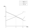
- FIG. 10 is a diagram showing an example of a graph showing changes in haptic vectors over time
- FIG. 4 is an explanatory diagram for explaining an example of a command value including amplitude information
- FIG. 9 is an explanatory diagram for explaining another example of command values including amplitude information
- FIG. 9 is an explanatory diagram for explaining another example of command values including amplitude information
- FIG. 4 is an explanatory diagram for explaining an example of operation processing of a control device according to the present disclosure
- FIG. 10 is an explanatory diagram for explaining an example of stick operation restrictions
- FIG. 10 is an explanatory diagram for explaining another example of stick motion limitation
- FIG. 10 is a diagram showing an example of a graph showing changes in haptic vectors over time
- FIG. 4
- FIG. 3 is an abstract diagram that abstracts a configuration related to haptic presentation of the operation device according to the present disclosure
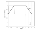
- 4 is a graph showing changes in position of each component in haptic presentation of the operation device according to the present disclosure
- FIG. 11 is an abstract diagram of a configuration related to haptic presentation of an operation device having a stopper composed of two parts
- FIG. 11 is an abstract diagram of a configuration related to haptic presentation of an operation device having a stopper composed of two parts
- FIG. 11 is an abstract diagram of a configuration related to haptic presentation of an operation device having a stopper composed of two parts
- FIG. 11 is an abstract diagram of a configuration related to haptic presentation of an operation device having a stopper composed of two parts
- FIG. 11 is an abstract diagram of a configuration related to haptic presentation of an operation device having a stopper composed of two parts
- FIG. 11 is an abstract diagram of a configuration related to haptic presentation of an operation device having a stopper composed of two parts
- FIG. 11 is
- FIG. 10 is a graph showing changes in position of each component in force presentation of an operation device having a stopper composed of two parts;
- FIG. 4 is a graph showing position changes of each configuration in force presentation of an operation device having a positive actuator that drives a positive stopper and a negative actuator that drives a negative stopper.
- FIG. 11 is an abstract diagram for explaining a modification of the shape of each configuration related to haptic presentation;
- FIG. 11 is an abstract diagram for explaining a modification of the shape of each configuration related to haptic presentation;
- Operation device overview An embodiment of the present disclosure relates to an operation device capable of further improving a user's operational feeling. First, with reference to FIG. 1, an outline of an operation device according to the present disclosure will be described.
- FIG. 1 is an explanatory diagram for explaining an overall overview of an operation device 1 according to the present disclosure. Recently, there is a need to provide a user with a comfortable operational feeling while presenting a haptic sensation to an operation device such as an analog stick.
- a controller used in a game can provide the user with a sense of realism and immersion by presenting haptic sensations corresponding to the character's state and actions when operating the character.
- an operation device that can be set without a haptic presentation request, such as when you want to concentrate on the action instead of always presenting the haptic.
- the operation device it may be desirable for the operation device to be capable of switching between a state in which the force sense is presented and a state in which the force sense is not presented (that is, it is possible to set whether to request the presentation of the force sense).
- the operation device 1 can be set with or without a force sense presentation request, and can improve the user's operational feeling regardless of whether the force sense is presented or not. is.
- the operation device 1 according to the present disclosure may be the entire housing (for example, a controller, etc.) including the analog stick as shown in FIG. 1, or the analog stick portion as shown in FIG. good.
- the analog stick portion as shown in FIG. 1 will be explained as the operation device 1 .
- a functional configuration example of the operation device 1 according to the present disclosure will be described below with reference to FIG. 2 .
- FIG. 2 is an explanatory diagram for explaining a functional configuration example of the operation device 1 according to the present disclosure.
- the operation device 1 is applied to stick operations in two-dimensional directions will be mainly described, but the operation device 1 according to the present disclosure can be applied to stick operations in one-dimensional directions or three-dimensional directions. is also applicable.
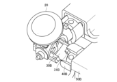
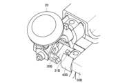
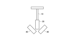
- the operation device 1 includes a stick 10, a limit ring 15, a stick cap 20, a rotator 30, a stopper 40, an actuator 50, an angle sensor 55, an angle sensor 60 and an origin return unit 70 .
- a stick 10 according to the present disclosure is an example of an operation unit that is tilted by a user's operation.
- the stick 10 can be tilted by the rotator 30 .
- the stick 10 can be tilted by the rotator 30 within a predetermined rotation range limited by the limit ring 15 .
- the stick 10 can be tilted by the user with the central axis of the rotating body 30A as the rotation axis. Also, the stick 10 can be tilted by the user with the central axis of the rotating body 30B as the rotation axis.
- the limiting ring 15 is a ring for rotating the rotating body 30 only within a predetermined range. For example, limit ring 15 is contacted when stick 10 is tilted a certain amount. As a result, the rotatable range of the rotating body 30 is also restricted.
- a stick cap 20 is a cap that covers the stick 10 .
- the user can tilt the stick 10 via the stick cap 20 by, for example, finger manipulation.
- the rotating body 30 rotates on the rotation axis of the rotating body 30, thereby enabling the stick 10 to be tilted within a predetermined rotation range.
- the rotating body 30A which is an example of the first movable part, allows the stick 10 to move within a predetermined range. More specifically, by rotating the central axis of the rotating body 30A as the first axis, the stick 10 can be tilted in both positive and negative directions in the rotational direction of the rotating body 30A.
- the rotating body 30B which is an example of the second movable part, rotates about the central axis of the rotating body 30B as a second axis, thereby tilting the stick 10 in both positive and negative directions in the rotation direction of the rotating body 30B.
- the central axis of the rotating body 30A and the central axis of the rotating body 30B may be orthogonal as shown in FIG.
- the rotating body 30A may have an elongated hole that does not interfere with the stick 10 when the stick 10 is tilted by the central axis of the rotating body 30B.
- the rotating body 30 has a contact portion that comes into contact with the movement of the stopper 40, which will be described later.
- the contact portion may have a convex structure as shown in FIG. 2, which will be described later in detail.
- the number of rotating bodies 30 is one, the number of stoppers 40, actuators 50, and angle sensors 55 and 60, which will be described later, may also be one.
- the stopper 40 is an example of a driven portion.
- the stopper 40 can move the contact portion of the rotating body 30 according to the driving force of the actuator 50 . Further, the stopper 40 contacts the contact portion of the rotating body 30 and can apply a load in the rotating direction of the rotating body 30 . As a result, the stick 10 is moved, and a force sensation is presented to the user via the stick 10 .
- the stopper 40 includes at least one or more parts.
- the stopper 40 shown in FIG. 2 is composed of one component. A specific example of the stopper 40 composed of two parts will be described later.
- the stopper 40A is an example of a first driven portion, and can move the contact portion in the rotation direction of the rotating body 30A. Due to the movement of the contact portion, a load is applied in the rotational direction of the rotating body 30A, and the operation device 1 can present the user with a force corresponding to the rotating direction of the rotating body 30A.
- the stopper 40B is an example of a second driven portion, and the contact portion can be moved in the rotation direction of the rotating body 30B. Due to the movement of the contact portion, a load is applied in the rotating direction of the rotating body 30B, and the operation device 1 can present the user with a force corresponding to the rotating direction of the rotating body 30B.
- Actuator 50 is an example of a driving unit driven under control of control device 100, which will be described later.
- the actuator 50A is an example of a first driving section, and can rotate the stopper 40A according to the driving force based on the command value acquired from the control device 100.
- the actuator 50B is an example of a second driving section, and can rotate the stopper 40B according to the driving force based on the command value acquired from the control device 100.
- the actuator 50 may be, for example, a DC rotary motor, but is not limited to such an example.
- the actuator 50 may be a brushless motor, a direct-acting motor, a solenoid, or any actuator that can be restricted from the left and right with a stopper structure.
- the angle sensors 55 and 60 are sensors capable of detecting angle information.
- the angle sensor 55 detects angle information of the stopper 40 .
- the angle sensor 60 detects angle information of the stick 10 .
- the origin return unit 70 has a structure that returns the stick 10 to the origin.
- the return-to-origin unit 70 is composed of a return-to-origin spring, an insert, and a slider.
- FIG. 3 is an explanatory diagram for explaining a functional configuration example of the control device 100 according to the present disclosure.
- the control device 100 according to the present disclosure includes a storage section 110, a power supply section 120, and a control section .
- control device 100 is provided by a housing (for example, a controller) that includes the operation device 1, but the control device 100 is arranged as a server at any place.
- the storage unit 110 holds software and various data.
- the storage unit 110 holds the relationship between the command value generated by the command value generation unit 135 and the voltage applied to the actuator 50 .
- the storage unit 110 may hold the relationship between the applied voltage and the torque generated by the applied voltage.
- torque is an example of driving force.
- the operation device 1 may be equipped with a sensor that detects the torque generated by the contact between the rotating body 30 and the stopper 40 .
- the sensor may then detect the torque generated by the applied voltage.
- the storage unit 110 may hold the relationship between the applied voltage and the torque detected by the sensor.
- the interface unit 131 can control the torque in a feedback manner based on the relationship held by the storage unit 110. For example, it is possible to perform control according to various conditions such as the age and sex of the user. .
- the power supply unit 120 supplies power to each component within the control device 100 .
- FIG. 3 shows an example in which the power supply unit 120 is mounted inside the control device 100 , the power supply unit 120 may be located outside the control device 100 .
- control unit 130 controls overall operations of the control device 100 .
- the control unit 130 according to the present disclosure includes, for example, an interface unit 131, an angle information reception unit 132, a communication unit 133, a setting reception unit 134, and a command value generation unit 135, as shown in FIG. .
- the interface unit 131 is a communication interface that transmits/receives signals including various information to/from the operation device 1 .
- the interface unit 131 receives angle information from the angle sensors 55 and 60 .
- the interface unit 131 also supplies the actuator 50 with a current corresponding to the command value generated by the command value generation unit 135 .
- the angle information acceptance unit 132 accepts angle information received by the interface unit 131.
- the angle information receiving section 132 receives the angle information of the stick 10 and the angle information of the stopper 40 received by the interface section 131 .
- the communication unit 133 performs various communications with other devices. For example, the communication unit 133 receives various signals from a server or a mobile terminal used by a user.
- the communication unit 133 receives information about whether or not there is a haptic presentation request set by the user on the application from the server or the mobile terminal.
- the communication unit 133 receives information about various objects on the application from the server or the mobile terminal. A specific example of information about various objects will be described later.
- the setting acceptance unit 134 accepts setting information received by the communication unit 133 .
- the setting accepting unit 134 accepts information regarding whether or not there is a haptic presentation request set by the user.
- the command value generator 135 generates a command value for driving the actuator 50 based on the angle information received by the angle information receiver 132 and the setting information received by the setting receiver 134 .
- the command value generation unit 135 calculates a force vector, which is an example of a force sense value, when a force sense presentation request is set. Also, the command value generator 135 may generate a command value based on the calculated force vector. Details regarding the calculation of the force vector and the generation of the command value will be described later.
- FIG. 4 is an explanatory diagram for explaining an overview related to haptic presentation according to the present disclosure.
- the rotor 30 has a convex structure 31 as a contact portion as shown in FIG.
- the convex structure 31 may be made of any material, but by using a material that can absorb impact, such as a cushioning material, it is possible to reduce an unintended sense of collision when presenting a force sensation to the user. .
- the user sets, for example, on the application whether or not to request the presentation of the force sensation. Then, the actuator 50B rotates the stopper 40B based on the force sense presentation request.
- FIG. 5A an example of driving the actuator 50 when the force sense presentation request is set to be present will be described.
- FIG. 5A is an explanatory diagram for explaining an example of driving the actuator 50B when the force sense presentation request is set.
- the actuator 50 rotates the stopper 40B under the control of the control device 100 .
- the actuator 50B rotates the stopper 40B according to the driving force based on the command value generated by the control device 100.
- the actuator 50B can apply a load to the rotating body 30B by contact between the end surface of the notch of the stopper 40B and the convex structure 31B of the rotating body 30B. This allows the actuator 50B to move the rotating body 30B.
- the stick 10 is also tilted with respect to the direction in which the rotating body 30B is moved.
- the operation device 1 according to the present disclosure can present the user with a force sensation according to the driving force of the actuator 50B in the direction in which the stick 10 is tilted.
- FIG. 6B an example relating to the driving of the actuator 50B when the haptic presentation request is set to be absent will be described.
- FIG. 5B is an explanatory diagram for explaining an example related to the driving of the actuator 50B when the haptic presentation request is not set.
- the actuator 50 rotates the stopper 40B under the control of the control device 100 .
- the actuator 50B moves the stopper 40B to a position where the protruded structure 31B of the rotating body 30B and the end surface of the notch of the stopper 40 do not come into contact when the stick 10 is tilted, as shown in FIG. may
- a position where the convex structure 31B of the rotating body 30B and the end surface of the notch of the stopper 40 do not contact may be expressed as a non-interfering position.
- the convex structure 31B of the rotating body 30B does not come into contact with the stopper 40B. That is, since the user is not provided with a sense of resistance corresponding to the contact, the user's operability can be further improved even when the haptic presentation request is set to be absent.
- the actuator 50 can provide the user with a haptic sensation by driving force based on the command value generated by the control device 100 .
- the process of generating command values by the control device 100 will be sequentially described.
- FIG. 6 is an explanatory diagram for explaining an example related to calculation of a force vector.
- a character C and a ball B exist in a virtual space S such as a game. Then, the user can operate the character C using the operation device 1 .
- a ball B is flying toward a character C that is at rest.
- Character C is an example of an operation object operated by a user
- ball B is an example of an interfering object that interferes with the operation object (that is, character C).
- the command value generation unit 135 calculates a haptic vector based on the information about various objects on the application received by the communication unit 133 .
- information about various objects on the application may include the characteristics of character C or the characteristics of ball B.
- the characteristics here include, for example, properties such as speed, size, elasticity, friction, electricity and surface roughness, or pre-designed scalar fields and vector fields.
- the properties of ball B may include various properties of ball B, such as flight speed, elasticity, or weight.
- the command value generator 135 calculates the force vector in the right direction. Further, the command value generator 135 calculates the magnitude of the force vector based on various information such as the speed of the ball B and the hardness (ie, elastic modulus) of the ball B.
- FIG. 6 the command value generator 135 calculates the force vector in the right direction. Further, the command value generator 135 calculates the magnitude of the force vector based on various information such as the speed of the ball B and the hardness (ie, elastic modulus) of the ball B.
- the command value generation unit 135 may calculate the magnitude of the haptic vector to be larger when the velocity of the ball B is higher than when the velocity of the ball B is low. As a result, it may be possible to more accurately present the speed and hardness of the ball to the user as a force sensation.
- the information about the target on the application may include the relative positional relationship between the operation object and the interfering object.
- information related to various positional relationships such as the position of the ball B with respect to the position of the character C may be included.
- the command value generation unit 135 may calculate a force vector based on information related to the state change of the operation device 1 .
- the information regarding the state change of the operation device 1 may include information regarding the angle at which the stick 10 is tilted.
- the character C is stopped, but it is possible for the character C to move by tilting the stick 10 by the user.
- the command value generator 135 may calculate the force vector with the angle at which the stick 10 is tilted as a starting point. This allows the command value generator 135 to calculate the force vector even when the ball B collides with the moving character C.
- command value generation unit 135 may calculate the force vector based on the elapsed time from the time when the operation device 1 started presenting the force.
- the command value generator 135 may calculate a force vector corresponding to the collision timing (for example, 0.1 seconds).
- the interfering object may be a field in which character C moves.
- the command value generator 135 may calculate a haptic vector based on a scalar field designed in advance for the field "swamp".
- the command value generation unit 135 may continuously calculate the pre-designed places where the resistance is strong and where the resistance is weak as the magnitude of the haptic vector. good. Thereby, the operation device 1 can present to the user the difficulty of moving peculiar to swamps as a force sensation.
- the command value generator 135 may calculate a force vector directed toward the origin from the angle at which the stick 10 is tilted. This may allow the user to more accurately feel the difficulty and resistance of the swamp.
- the command value generation unit 135 may, for example, select a slope, stairs, a state in which the character C has luggage, a swimming action, or a state in which the character Various states such as C's stamina may be reflected in the haptic vector.
- the command value generating unit 135 may calculate the sense of resistance when manipulating a tool used by character C as a force vector. More specifically, the command value generation unit 135 can thereby provide the user with a sense of resistance when the character C performs an action using a tool (for example, an action of drawing a bow, etc.).
- the command value generator 135 may calculate a force vector in the normal direction of the wall when the character C collides with the wall. Also, the command value generator 135 may calculate the magnitude of the haptic vector from the traveling direction of the character C or the normal line of the wall. In addition, the command value generating unit 135, for example, immediately after the character C collides with the wall (for example, about 0.5 seconds after the collision timing) calculates a large force vector, and then calculates a small force vector. good too.
- the interfering object may be an object related to character C's operation.
- object related to the operation of the character C an example of a ring-shaped command object will be described.
- FIG. 7 is an explanatory diagram for explaining an overview of command objects.
- a command object according to the present disclosure may be, for example, an object having ring-shaped options as shown in FIG.
- the command object consists of, for example, a reference circle (the circle containing "0" shown in FIG. 7) as the center, and a ring-shaped area (see FIG. It may also be an object having a feature surrounded by a region containing "1" to "8").
- the user may be able to display the command object on the application by, for example, performing a predetermined operation on the operation device 1, or display the command object in response to an action such as a voice uttered by the user. It may be possible to display it on the application.
- options are included in each area containing "1" to “8".
- the user can select an option in the tilted direction by tilting the stick 10 from the origin position in a certain direction of an area containing options "1" to "8".
- FIG. 8 is an explanatory diagram for explaining an example of a force vector when the stick 10 is tilted from "0" toward an area with other numbers. For example, when the user wants to select an option in a number area, the user tilts the stick 10 from the origin position toward the number area.
- the command value generation unit 135 may, for example, calculate a force vector in a direction that inhibits movement from "0" in the hatched area VH1 shown in FIG.
- the hatched area VH1 may be an area including a prescribed range from the boundary where "0" transitions to another number.
- the command value generator 135 may calculate the force vector in the direction of the arrow in the hatched area VH1 shown in FIG. . At this time, the command value generator 135 may calculate the magnitude of the force vector to increase as the stick 10 is tilted from "0" to "2" in the hatched area VH1.
- the option in the "2" area may be selected.
- the option in the area "2" may be selected when an operation related to confirmation of the option is performed. .
- FIG. 9 is an explanatory diagram for explaining an example of a force vector when the stick 10 is tilted from “1" to "2" or "8". For example, after tilting the stick 10 to select an option in the "1" area, the user may further select an option adjacent to the "1" area.
- the command value generation unit 135 may, for example, calculate a force vector in a direction that inhibits movement from "1" in the hatched area VH2 shown in FIG.
- the command value generator 135 when the user tilts the stick 10 from the area “1" toward the area "2", the command value generator 135 generates force in the direction of the arrow in the hatched area VH2 shown in FIG. You may calculate a wake vector.
- the command value generator 135 calculates the force vector in the direction of the arrow in the hatched area VH3 shown in FIG. good too.
- the command value generation unit 135 may calculate a haptic vector corresponding to the area containing the option each time the area is moved. As a result, the command value generation unit 135 can provide the user with a feeling of having crossed over the area when moving to another option area, and a feeling of being within the area after crossing over.
- the number of rings surrounding the command object may be double or more.
- the command value generator 135 may calculate a command value for controlling the actuator 50 based on the calculated force vector.
- FIGS. 10 to 16B specific examples of calculation of command values according to the present disclosure will be sequentially described.
- command value> There are, for example, two methods of presenting the haptic sensation to the user: a momentary presentation method and a continuous presentation method.
- the command values for the instantaneous presentation method and the command values for the continuous presentation method will be described below.
- the drive force of the actuator 50 causes the stopper 40 to collide with the convex structure 31.
- FIG. 10 an example of a method of presenting an instantaneous force sense will be described.
- FIG. 10 is an explanatory diagram for explaining an example of a method of presenting an instantaneous force sensation.
- the position of the stopper 40 is indicated by a solid line
- the position of the stick 10 is indicated by a broken line.
- the position of the stick 10 here indicates, more specifically, the position of the convex structure 31 of the rotating body 30 . Since the stick 10 moves in conjunction with the convex structure 31 , for convenience of explanation, the position of the convex structure 31 is assumed to be the position of the stick 10 . Also, the position of the stick 10 and the position of the stopper 40 indicate the positions of the rotor 30 around the axis.
- the violent force generated when the stopper 40 collides with the convex structure 31 increases.
- the position of the stopper 40 and the position of the stick 10 are close to each other (that is, when they are not apart from each other by a certain distance)
- the violent force generated by the collision of the stopper 40 with the convex structure 31 can be reduced.
- the actuator 50 according to the present disclosure may present an instantaneous sense of force using the relationship between the distance between the stopper 40 and the stick 10 and the violent force generated by the collision.
- the actuator 50 shifts the position of the end face of the notch of the stopper 40 to a predetermined offset from the convex structure 31 of the rotating body 30. They may be separated by a distance dx. However, when the end surface of the notch of the stopper 40 and the convex structure 31 are separated by a predetermined offset distance dx or more, the actuator 50 performs control to separate the position of the end surface of the notch of the stopper 40 from the convex structure 31. It doesn't have to be.
- the impact mode is an example of an instantaneous haptic presentation mode.
- the actuator 50 After the end surface of the notch of the stopper 40 collides with the convex structure 31 of the rotating body 30, the actuator 50 returns the position of the stopper 40 to the position before the collision (for example, the original position of the stopper 40). may Thereby, a force sensation with a greater impact can be presented to the user.
- the command value includes the amount of change in the position of the stopper 40 with respect to the time from time t3 when the position of the stopper 40 is separated by the offset distance dx to time t4 when the force is applied to the stick 10 (that is, 10 ) may be included .
- the actuator 50 Under the control of the control device 100 , moves the end face of the notch of the stopper 40 into the convex shape of the rotating body 30 with a force corresponding to the command value. It may also collide with structure 31 .
- the force generated by the collision of the convex structure 31 of the rotating body 30 with the stopper 40 momentarily presents a haptic sensation.
- the stopper 40 may be moved to a position where it does not come into contact with the convex structure 31, thereby instantaneously providing the user with a force sensation. .
- the user can be presented with a more vivid sensation of a collision with an interfering object.
- the direction of the force vector is not only the vertical direction corresponding to either one of the rotating bodies 30A or 30B, or the horizontal direction corresponding to the other, but also oblique directions including both vertical and horizontal components.
- oblique direction is expressed as one collision, it is necessary for the stopper 40A to collide with the rotating body 30A and the stopper 40B to collide with the rotating body 30B at the same timing.
- the command value generation unit 135 generates a command value such that the stoppers 40A and 40B collide with the rotating bodies 30A and 30B within an error range that does not allow the user to perceive the difference in collision timing. may be generated.
- the command value generation unit 135 may control the timing at which the interface unit 131 transmits command values to each of the actuators 50A and 50B.
- the command value generation unit 135 determines the actuator 50A corresponding to the component with the large ratio. Alternatively, a command value for driving only one of the actuators 50B may be generated.
- the command value generation unit 135 may generate a command value that instantaneously presents the user with a sense of force as notification means for notifying that the UI cursor has moved by one square or has moved to the end.
- the command value generator 135 may change the magnitude of the force sense to be presented to the user according to the number of times the force sense due to collision is presented.
- FIGS. 11A and 11B are explanatory diagrams for explaining specific examples of command values generated when the ball B collides with the character C multiple times.
- the user may have a better sense of direction when multiple collisions occur than when the user collides once.
- the command value generator 135 may generate a command value such that the feedback is the strongest for the first collision, and the strength of the feedback is gradually reduced for the second and subsequent collisions.
- the command value generator 135 may generate a command value such that the feedback is the strongest for the first collision, and the strength of the feedback is uniformly reduced for the second and subsequent collisions.
- command value generator 135 may generate a command value in which the strength of feedback from the second time onward is changed as described above, according to the number of balls B that collide with each other per unit time.
- a specific example of an instantaneous presentation method has been described above as a method of presenting a haptic sensation to the user. Vibration can be presented by repeating the momentary presentation of the sense of force due to the collision of the stopper 40 and the rotating body 30 . A specific example of vibration presentation will be described later. Next, a specific example of a continuous presentation method will be described as a method of presenting the haptic sensation to the user.
- continuous presentation method For example, as a continuous presentation method, it is assumed that the above-described character moves through a swamp, or the character draws a bow, or performs an operation using a command object.
- the command value generator 135 may first drive the actuator 50 to a position where the convex structure 31 of the rotating body 30 and the stopper 40 come into contact.
- the command value generator 135 may change the driving force of the actuator 50 according to the tilt of the operation object and the tilt of the stick 10 .
- command value generation unit 135 may switch to continuous presentation after presenting the above-described momentary haptic.
- continuous haptic presentation method an example of a continuous haptic presentation method will be described with reference to FIG. 12 .
- FIG. 12 is an explanatory diagram for explaining an example of a continuous haptic presentation method.
- the actuator 50 may perform control according to the distance between the stopper 40 and the stick 10 .
- the soft collision mode is an example of a continuous haptic presentation mode.
- the actuator 50 when the actuator 50 is set to the soft collision mode, if the distance between the end surface of the notch of the stopper 40 and the convex structure 31 of the rotating body 30 is greater than or equal to the first distance, the actuator 50 moves at the first speed.
- the rotating body 30 may be rotated.
- the first distance is, for example, the distance between the stopper 40 (more specifically, the end face of the notch of the stopper 40) and the stick 10 (more specifically, the rotating body 30) at time t1 shown in FIG. is the distance between the convex structure 31) of
- the first speed is the speed of the stopper 40 during the time t 0 to t 1 shown in FIG. good.
- the stopper 40 and stick 10 may keep a constant distance and not collide. Therefore, when the distance between the end surface of the notch of the stopper 40 and the convex structure 31 of the rotating body 30 is less than the first distance, the actuator 50 rotates at a second speed different from the above-described first speed. Body 30 may be rotated.
- the second speed is the speed of the stopper 40 during the time t 1 to t 2 shown in FIG. 12, and may be a constant speed controlled to such an extent that the collision of the stopper 40 is not perceived by the user.
- the first speed and the second speed are not limited to the examples described above.
- the first speed and the second speed may be constant speeds or speeds defined by a function such as an exponential function.
- a larger voltage is applied to the actuator 50 as the distance increases.
- a constant voltage is applied to the actuator 50 when the distance between the end surface of the notch of the stopper 40 and the convex structure 31 of the rotating body 30 reaches the first distance. Furthermore, after the end face of the notch of the stopper 40 collides with the convex structure 31 of the rotating body 30, the actuator 50 is applied with a large voltage again so that the user is presented with a continuous force sensation.
- the stopper 40 rotates quickly when it is away from the stick 10, and rotates slowly as it approaches the stick 10. It can hit the stick 10 with imperceptibly weak force.
- the command value from the application provides the user with a continuous force sensation.
- a force-related command value may be continuously sent from the application.
- the actuator 50 brings the stopper 40 closer to the stick 10 again in the above-described procedure to cause it to collide with the stick 10, thereby presenting a continuous sense of force to the user.
- actuator 50A and the actuator 50B different control standards may be used for the actuator 50A and the actuator 50B.
- actuator 50A uses the above-described first distance, first speed, and second speed as a reference for control
- actuator 50B uses a second distance and a third speed different from those of actuator 50A.
- Velocity, a fourth velocity may be used as a control criterion.
- the same control reference may be used for the actuator 50A and the actuator 50B.
- the first and second distances, the first and third velocities, and the second and fourth velocities may each indicate the same value.
- the command value generation unit 135 may generate a command value related to the motion restriction of the stick 10 when the motion restriction of the stick 10 is requested.
- FIG. 13A is an explanatory diagram for explaining an example of motion restrictions of the stick 10.
- FIG. FIG. 13A is a circle showing the movable range of the stick 10, and the command value generating section 135 may set motion limits in the hatched area, for example.
- the command value generator 135 may generate a command value that hinders the tilting action. In this case, when the user tries to incline the stick 10 to the hatched area, the user feels as if he or she is being pushed back toward the non-hatched area.
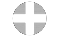
- FIG. 13B is an explanatory diagram for explaining another example of the motion limitation of the stick 10.
- the command value generation unit 135 sets the rotation range of the stick 10 as the non-hatched area of the cross key, as shown in FIG. 13B. You can limit the range. Due to the motion limitation described above, the command value generation unit 135 can provide the user with assistance related to the motion of the stick 10 .
- the command value generation unit 135 may present the user with a force sensation due to vibration.
- the command value generator 135 may generate a command value by converting the force vector into vibration, sound, or the like.
- FIG. 14 is a diagram showing an example of a graph showing changes over time in haptic vectors.
- the magnitude of the force vector shown in FIG. 14 may be, for example, the square root of the sum of the squares of the magnitude of the force vector in the vertical direction and the magnitude in the horizontal direction.
- the command value generator 135 may generate a command value including an amplitude corresponding to the calculated force vector.
- the amplitude may be expressed as an envelope.
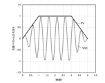
- FIG. 15 is an explanatory diagram for explaining an example of command values including amplitude information.
- the command value generator 135 calculates an envelope based on the force vector FV. Then, the command value generator 135 may generate the sinusoidal vibration VS1 based on the calculated envelope as the command value.
- FIGS. 16A and 16B are explanatory diagrams for explaining other examples of command values including amplitude information.
- the command value generator 135 may generate a command value including amplitude information corresponding to the change amount of the force vector.
- the command value generator 135 calculates the change amount AC of the force vector FV with respect to time.
- the command value generator 135 calculates an envelope based on the calculated amount of change AC. Then, the command value generator 135 may generate the sinusoidal vibration VS2 based on the calculated envelope as the command value.
- the command value generation unit 135 can notify the user of a change in the object operated by the user, for example, when the character C shown in FIG. 6 enters or exits the swamp. can be
- the command value generation unit 135 calculates the envelope based on the force vector
- the command value generation unit 135 may calculate the envelope and the frequency based on the force vector. This increases the degree of freedom related to vibration presentation, and the command value generation unit 135 can present various vibrations to the user according to the situation of the character C and the environment.
- the operation device 1 may further include a vibration motor as an example of a vibration presenting unit.
- the operation device 1 may further include a speaker for outputting a command value obtained by converting a haptic vector into sound.
- vibration may be generated by repeated collisions of a combination of at least one of the stopper 40A and the rotating body 30A and the stopper 40B and the rotating body 30B.
- the stopper 40 is an example of a vibration presenting section.
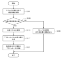
- FIG. 17 is an explanatory diagram for explaining an example of operation processing of the control device 100 according to the present disclosure.
- the communication unit 133 acquires tilt information indicating the tilt of the stick 10 (S101).
- control unit 130 determines whether or not the user has set a haptic presentation request (S105). If no presentation request is set (S105/No), the process proceeds to S109, and if presentation request is set (S105/Yes), the process proceeds to S113.
- the interface unit 131 moves the position of the stopper 40 to a non-interfering position with the stick (S109), and the control device 100 ends the process.
- the command value generation unit 135 calculates a haptic vector based on the information about the target on the application (S113).
- the command value generator 135 calculates a command value for the actuator 50 based on the calculated force vector (S117).
- the interface unit 131 supplies a current corresponding to the calculated command value to the actuator 50 to drive the actuator 50 (S121), and the control device 100 ends the processing.
- the haptic presentation method of the operation device 1 according to the present disclosure is not limited to the examples described above.
- a specific example of the haptic presentation method of the operation device 1 will be described.
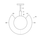
- FIG. 18 is an abstract diagram that abstracts the configuration related to haptic presentation of the operation device 1 according to the present disclosure.
- the stopper 40 can present positive and negative force sensations to the user by the collision of the rotating body 30 against the convex structure 31 .
- the stopper 40 that generates force in the positive direction is referred to as the positive stopper 410
- the stopper 40 that generates force in the negative direction is referred to as the negative stopper 420.
- the stopper 40 configured by one part the right side of the broken line shown in FIG.
- the end surface 411 of the positive stopper 410 contacts (collides with) the convex structure 31 of the rotating body 30
- the user is presented with a force in the positive direction.
- the end surface 421 of the negative stopper 420 contacts (collides with) the convex structure 31 of the rotating body 30, the force in the negative direction is presented to the user.
- FIG. 19 is a graph showing changes in the position of each configuration in haptic presentation of the operation device 1 according to the present disclosure.
- the position of the stick 10 is indicated by a dashed line
- the position of the positive stopper 410 is indicated by a solid line
- the position of the negative stopper 420 is indicated by a dashed line.
- FIG. 19 illustrates an example in which the actuator 50 controls the stopper 40 so as to present a force sensation toward the origin position x0 of the stick 10.
- FIG. 19 illustrates an example in which the actuator 50 controls the stopper 40 so as to present a force sensation toward the origin position x0 of the stick 10.
- the actuator 50 brings the negative stopper 420 into contact with the stick 10 tilted in the positive direction, thereby presenting a force sensation in the negative direction. Then, at time t11 , after the stick 10 reaches the origin position x0, when the stick 10 is further tilted in the negative direction, the actuator 50 controls the positive stopper 410 to contact the stick 10. , presents a force sensation in the positive direction. Then, when a command value for ending the force sense presentation is obtained (time t 13 shown in FIG. 19), the actuator 50 moves the stopper 40 to a position where it does not come into contact with the stick 10 .
- the stopper 40 when the stopper 40 is composed of a single component, the positive stopper 410 and the negative stopper 420 move in conjunction with each other.
- a blank time t 11 to t 12 of haptic presentation may occur according to the width. Occurrence of the blank times t 11 to t 12 may cause an event in which the desired haptic sensation is not presented to the user.
- the stopper 40 may be composed of two separate parts, a positive stopper 410 and a negative stopper 420 .
- the actuator 50 may rotate the positive stopper 410 and the negative stopper 420 in line-symmetrical rotational directions by converting the rotation of the actuator 50 using a gear.
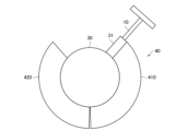
- 20A to 20D are abstract diagrams that abstract the configuration related to the haptic presentation of the operation device 1 having the stopper 40 composed of two parts.
- the positive stopper 410 and the negative stopper 420 have a pinching structure by converting the driving force of the actuator 50 with a gear.
- the pinching configuration of the positive and negative stoppers 410, 420 allows the stoppers 40 to have notches that dynamically open and close, as shown in FIGS. 20A-20D.
- FIG. 21 is a graph showing changes in position of each component in presenting the force sensation of the operation device 1 having the stopper 40 composed of two parts.
- the graph shown in FIG. 21 is a graph showing the position of each configuration (stick 10, positive stopper 410 and negative stopper 420) shown in FIG.
- each component of the operation device 1 shown in FIGS. 20A and 20B is indicated by each line (solid line, dashed line, dashed line) at times t 0 to t 21 shown in FIG. 21, and FIGS. 21 are indicated by lines (solid line, dashed line, dashed-dotted line) at times t 21 to t 22 shown in FIG.
- the positive stopper 410 and the negative stopper 420 that constitute the stopper 40 rotate so as to sandwich the convex structure 31 according to the driving force of the actuator 50 .
- the negative stopper 420 rotates according to the driving force of the actuator 50 so as to push back the position of the convex structure 31 at time t0 to the origin position x0.
- the positive stopper 410 is interlocked with the rotation of the negative stopper 420 and rotates in the direction opposite to the direction of rotation of the negative stopper 420 (that is, in the rotational direction of line symmetry).
- the width of the notch of the stopper 40 is dynamically narrowed, and the blank time of force sense presentation (time t 11 to t 12 shown in FIG. 19) can be reduced. .
- the positive stopper 410 and the negative stopper 420 are driven by the driving force of one actuator 50, but the operation device 1 according to the present disclosure drives the positive stopper 410.
- a positive actuator and a negative actuator driving the negative stopper 420 may each be provided.
- FIG. 22 is a graph showing changes in position of each configuration in force presentation of the operation device 1 having a positive actuator that drives the positive stopper 410 and a negative actuator that drives the negative stopper 420.
- the positive actuator and the negative actuator may be collectively expressed as a plurality of actuators 50 .
- the positive stopper 410 and the negative stopper 420 can operate independently as shown in FIG. can be switched between positive and negative without delay (that is, without blank time). Further, by operating a plurality of actuators 50, an arbitrary stick position ax can be changed as appropriate.
- the actuator 50 moves the positive stopper 410 and the negative stopper 420 to the non-interfering position of the stick 10 .
- the actuator 50 moves the positive stopper 410 and the negative stopper 420 to the non-interfering position of the stick 10 .
- the number of parts constituting the stopper 40 and the number of actuators 50 corresponding to the number of parts are not limited to one or two.
- the number of parts constituting the stopper 40 and the number of actuators 50 corresponding to the number of parts may be three or more.
- each configuration for example, the rotating body 30 and the stopper 40 related to the haptic presentation is not limited to the above examples.
- modified examples of each configuration related to haptic presentation will be described with reference to FIGS. 23A and 23B.
- Modification 23A and 23B are abstract diagrams for explaining a modification of the shape of each configuration (for example, rotating body 30 and stopper 40) related to force presentation.
- each configuration for example, rotating body 30 and stopper 40
- the stopper 40 may have a convex structure. At this time, the stopper 40 may not have a notch.
- each configuration related to the force sense presentation may be a structure capable of limiting the movable range of the stick 10.
- the shape of the stopper 40 has a notch as shown in FIG. 23B. It may be a simpler structure.
- the stopper 40 is made up of two parts, it is possible to reduce the weight of the operation device 1 by reducing the size of the two parts of the stopper 40 .
- the size relationship between the convex structure 31 of the rotating body 30 and the notch of the stopper 40 is not limited to the above example.
- the size of the convex structure 31 is not particularly limited as long as it fits in the notch of the stopper 40 .
- the operation device 1 is used for applications such as games, but the application of the operation device 1 according to the present disclosure is not limited to such examples.
- the operation device 1 according to the present disclosure may be used in applications such as remote controllers, operation of medical equipment, controllers for mobile robots and drones, and operation of electric wheelchairs.
- the stick 10 according to the present disclosure has been described as a rotating stick using the rotating body 30, but the stick 10 may be a sliding stick.
- the stick 10 according to the present disclosure has been described as a two-dimensional stick that can be tilted two-dimensionally. It may even be a three-dimensional stick that is possible. Note that when the stick 10 is two-dimensional or more, the command value generation unit 135 according to the present disclosure decomposes the haptic vector into components in each dimension and calculates the A haptic can be presented to the user.
- each component of the operation device 1 has been described with reference to FIG. 2, the arrangement of the components of the operation device 1 is not limited to this example.
- Each component such as the actuator 50 may be arranged at any position depending on the type and arrangement of gears.
- the actuator 50A rotates the stopper 40A to bring the end surface of the notch of the rotating body 30A into contact with the abutting portion of the rotating body 30A, and the actuator 50B rotates the stopper 40B, causing the stopper to rotate.
- An example of bringing the end face of the notch 40B into contact with the contact portion of the rotating body 30B has been described.
- the actuators 50A and 50B are independently controlled when the rotating bodies 30A and 30B rotate, but the structure for suppressing the tilting motion of the stick 10 is not limited to this example.
- the stopper 40A may be a mechanism that applies a brake to the rotating body 30 by friction instead of contact by the end face of the notch.
- it may be a mechanism that brakes both the rotating shaft by the rotating body 30A and the rotating shaft by the rotating body 30B at the same time.
- one actuator 50 can suppress the rotation of two axes.
- the command value generation unit 135 may perform correction related to erroneous input prevention according to such a situation. Then, the command value generation unit 135 may generate a command value corrected for preventing erroneous input.
- the command value generation unit 135 may provide several seconds of non-operable time with the stick 10 after momentarily presenting the haptic.
- the command value generation unit 135 returns the stick 10 to the vicinity of the position before the contact portion between the stopper 40 and the rotating body 30 collided. It is not necessary to accept the operation input by the stick 10 until.
- the command value generation unit 135 may perform control so that the presentation of the force sense is turned off when a predetermined angle is reached from the angle reference of the stick 10 after presenting the force sense. Specifically, the command value generation unit 135 may perform control such that, after presenting the force sense, presentation of the force sense is turned off at +5° from the origin. This can prevent the stick 10 from rebounding at an unintended angle. Note that the angle reference is not limited to the origin.
- each step in the processing of the control device 100 in this specification does not necessarily have to be processed in chronological order according to the order described as the flowchart.
- each step in the processing of the information processing system may be processed in an order different from the order described as the flowchart or in parallel.
- an operation unit that is moved by a user's operation; a first movable portion that enables the operation portion to move within a predetermined range; a first drive; a first driven part including at least one component and capable of moving a contact part of the first movable part according to the driving force of the first driving part; operating device with (2) a second movable section that allows the operation section to move along a second axis that is different from the first axis along which the operation section can be moved by the first movable section; a second drive; a second driven part that includes at least one or more components and is capable of moving a contact part of the second movable part according to the driving force of the second driving part;
- the operation device according to (1) above, further comprising: (3)
- the first movable part is a first rotating body that enables the operation unit to be tilted with respect to the first axis by the user's operation;
- the second movable part is A second rotating body that allows the operation
- a component included in the first driven portion and the second driven portion has an end surface;
- the first rotating body and the second rotating body are It is movable by contact between the end surface and the contact portion,
- the first driven portion and the second driven portion have cutouts,
- the first rotating body and the second rotating body are It is movable by contact between the end surface of the notch and the contact portion,
- the first driving section and the second driving section are Rotating the first driven part or the second driven part based on the presence or absence of a preset force sense presentation request;
- the operation device according to (4) or (5) are
- the first driving section and the second driving section are rotating the first driven part or the second driven part when the haptic presentation request is set to be present;
- the first driving section and the second driving section are When the haptic presentation request is set to ON, the rotational direction of the first rotating body is changed by the contact between the first driven portion and the contact portion of the first rotating body according to the driving force. and applying a load in the direction of rotation of the second rotating body due to contact between the second driven portion and the contact portion of the second rotating body.
- the operation device according to (7) above.
- the first driving section and the second driving section are The first driven portion and the second driven portion are positioned so as not to come into contact with each other when the operation portion is tilted within the predetermined rotation range when the force sense presentation request is set to none. move the The operation device according to (7) or (8).
- the driving forces of the first driving section and the second driving section are based on a haptic value based on the characteristics of an operation object operated by tilting the operation unit; The operation device according to any one of (3) to (9).
- the haptic value is calculated based on the characteristics of an interfering object that interferes with the operation object; The operation device according to (10) above.
- the haptic value is Calculated based on the angle at which the operation unit is tilted, The operation device according to (10) or (11).
- the haptic value is Calculated based on the elapsed time since the driving force was presented, The operation device according to any one of (10) to (12).
- the driving force is Based on a command value for driving the first driving unit or the second driving unit generated based on the force sense value, The operation device according to any one of (10) to (13).
- the command value is When presenting a momentary haptic, the strength of the feedback varies depending on the number of times the haptic is presented. The operation device according to (14) above.
- the first drive unit When the momentary force sense presentation mode is set, after the end surface of the first driven portion is separated from the contact portion of the first rotating body by a predetermined offset distance, the first driven portion is moved. colliding the end surface of the driving portion with the contact portion of the first rotating body;
- the second drive unit When the momentary force sense presentation mode is set, after the end surface of the second driven part is separated from the contact part of the second rotating body by a predetermined offset distance, the second driven part is moved. causing the end surface of the part to collide with the contact part of the second rotating body;
- the operation device according to (14) or (15).
- the command value is Generated based on the continuously calculated force sense value when continuously presenting the sense of force, The operation device according to any one of (14) to (16).
- the first drive unit When the continuous haptic presentation mode is set, if the distance between the end surface of the first driven portion and the contact portion of the first rotating body is equal to or greater than the first distance, the first and the distance between the end surface of the first driven portion and the contact portion of the first rotating body is less than the first distance, the second speed to rotate the first rotating body with The second drive unit When the continuous haptic presentation mode is set and the distance between the end surface of the second driven portion and the contact portion of the second rotating body is equal to or greater than the second distance, the third A fourth speed when the second rotating body is rotated at a speed and the distance between the end surface of the second driven portion and the contact portion of the second rotating body is less than the second distance rotating the second rotating body with The operation device according to any one of (14) to (17).
Landscapes
- Engineering & Computer Science (AREA)
- Physics & Mathematics (AREA)
- General Physics & Mathematics (AREA)
- General Engineering & Computer Science (AREA)
- Multimedia (AREA)
- Theoretical Computer Science (AREA)
- Automation & Control Theory (AREA)
- Human Computer Interaction (AREA)
- Position Input By Displaying (AREA)
- User Interface Of Digital Computer (AREA)
Abstract
Description
1.操作デバイスの概要
1.1.概要
1.2.操作デバイス1の機能構成例
1.3.制御装置100の機能構成例
2.実施例
2.1.力覚提示に係る概要
2.2.力覚ベクトルの演算
2.3.指令値の生成
3.動作処理例
4.力覚提示方法の具体例
5.補足
本開示の一実施形態は、ユーザの操作感をより向上させることが可能な操作デバイスに関する。まず、図1を参照し、本開示に係る操作デバイスの概要を説明する。
図1は、本開示に係る操作デバイス1の全体概要を説明するための説明図である。昨今、アナログスティック等の操作デバイスに力覚を提示しつつ、ユーザに快適な操作感を提供したいといったニーズがある。
図2は、本開示に係る操作デバイス1の機能構成例を説明するための説明図である。本明細書では、操作デバイス1が二次元方向のスティック操作に対して適用する場合について主に説明するが、本開示に係る操作デバイス1は、一次元方向または三次元方向のスティック操作に対しても適用可能である。
本開示に係るスティック10は、ユーザの操作により傾けられる操作部の一例である。例えば、スティック10は、回転体30により傾けることが可能である。より具体的には、スティック10は、回転体30により制限リング15により制限された所定の回転範囲内で傾けることが可能である。
本開示に係る制限リング15は、回転体30を所定の範囲内でのみ回転させるためのリングである。例えば、制限リング15は、スティック10が一定値傾けられた際に接触される。この結果、回転体30の回転可能な範囲も制限される。
本開示に係るスティックキャップ20は、スティック10に被せるキャップである。ユーザは、例えば手指による操作で、スティックキャップ20を介してスティック10を傾けることが可能である。
本開示に係る回転体30は、当該回転体30の回転軸で回転することにより、所定の回転範囲内でスティック10を傾けることを可能にする。
本開示に係るストッパ40は、被駆動部の一例である。ストッパ40は、アクチュエータ50の駆動力に応じて、回転体30が有する当接部を移動可能である。また、ストッパ40は、回転体30が有する当接部を接触し、回転体30の回転方向に対して荷重を印加することが可能である。これにより、スティック10が移動されることや、スティック10を介してユーザに力覚が提示される。
本開示に係るアクチュエータ50は、後述する制御装置100の制御に従って駆動する駆動部の一例である。例えば、アクチュエータ50Aは、第1の駆動部の一例であり、制御装置100から取得された指令値に基づく駆動力に応じて、ストッパ40Aを回転させることが可能である。
本開示に係る角度センサ55、60は、角度情報を検出可能なセンサである。例えば、角度センサ55は、ストッパ40の角度情報を検出する。また、角度センサ60は、スティック10の角度情報を検出する。
本開示に係る原点復帰部70は、スティック10を原点に復帰させる構造である。例えば、原点復帰部70は、原点復帰用のバネ、インサートおよびスライダにより構成される。
図3は、本開示に係る制御装置100の機能構成例を説明するための説明図である。図3に示すように本開示に係る制御装置100は、記憶部110と、電源部120と、制御部130と、を備える。
本開示に係る記憶部110は、ソフトウェアおよび各種データを保持する。例えば、記憶部110は、指令値生成部135により生成される指令値と、アクチュエータ50への印加電圧との関係を保持する。また、記憶部110は、印加電圧と、当該印加電圧により発生するトルクとの関係を保持してもよい。なお、トルクは、駆動力の一例である。
本開示に係る電源部120は、制御装置100内の各構成に電力を供給する。図3においては、電源部120が制御装置100の内部に搭載される例が示されているが、電源部120は、制御装置100の外部に位置していてもよい。
本開示に係る制御部130は、制御装置100の動作全般を制御する。本開示に係る制御部130は、図3に示すように、例えば、インターフェース部131と、角度情報受入部132と、通信部133と、設定受入部134と、指令値生成部135と、を備える。
<2.1.力覚提示に係る概要>
図4は、本開示に係る力覚提示に係る概要を説明するための説明図である。回転体30は図4に示すような凸状構造31を当接部として有する。
図6は、力覚ベクトルの演算に係る一例を説明するための説明図である。図6に示す一例では、ゲームなどの仮想空間S上にキャラクターCとボールBが存在する。そして、ユーザは操作デバイス1を用いて、キャラクターCを操作することが可能である。
力覚をユーザに提示する方法は、例えば、瞬間的な提示方法と、継続的な提示方法の2通りが挙げられる。以下では、瞬間的な提示方法に係る指令値と、継続的な提示方法に係る指令値をそれぞれ説明する。
まずは、瞬間的な提示方法の具体例を説明する。例えば、瞬間的な提示方法は、図6に示したキャラクターCにボールBが衝突した場合が想定される。
例えば、継続的な提示方法は、上述したキャラクターが沼地を移動する場合や、キャラクターが弓を引く動作や、コマンドオブジェクトによる操作が行われる場合等が想定される。
ユーザは、動作に集中したい場合等において、力覚の提示要求を無しに設定する場合がある。この場合、指令値生成部135は、力覚ベクトルを振動や音などに変換した指令値を生成してもよい。
図17は、本開示に係る制御装置100の動作処理の一例を説明するための説明図である。まず、通信部133は、スティック10の傾きを示す傾き情報を取得する(S101)。
図18は、本開示に係る操作デバイス1の力覚提示に係る構成を抽象化した抽象図である。上述した実施例では、ストッパ40が1部品により構成される例を説明した。ストッパ40は、回転体30の凸状構造31への衝突により正負のそれぞれの力覚をユーザに提示することが可能である。
図23Aおよび図23Bは、力覚提示に係る各構成(例えば、回転体30、ストッパ40)の形状の変形例を説明するための抽象図である。例えば、本明細書では、回転体30が凸状構造31を有し、ストッパ40が切り欠きを有する例を主に説明したが、図23Aに示すように、回転体30が切り欠きを有していてもよく、ストッパ40が凸状構造を有していてもよい。この際に、ストッパ40は、切り欠きを有していなくてもよい。
以上、添付図面を参照しながら本開示の好適な実施形態について詳細に説明したが、本開示はかかる例に限定されない。本開示の属する技術の分野における通常の知識を有する者であれば、請求の範囲に記載された技術的思想の範疇内において、各種の変更例または修正例に想到し得ることは明らかであり、これらについても、当然に本開示の技術的範囲に属するものと了解される。
(1)
ユーザの操作により移動される操作部と、
所定の範囲内で前記操作部を移動させることを可能にする第1の可動部と、
第1の駆動部と、
少なくとも1以上の部品を含み、前記第1の駆動部の駆動力に応じて、前記第1の可動部の当接部を移動可能である第1の被駆動部と、
を有する操作デバイス。
(2)
前記第1の可動部により前記操作部の移動が可能な第1の軸と異なる第2の軸に、前記操作部を移動させることを可能にする第2の可動部と、
第2の駆動部と、
少なくとも1以上の部品を含み、前記第2の駆動部の駆動力に応じて、前記第2の可動部の当接部を移動可能である第2の被駆動部と、
を更に有する、前記(1)に記載の操作デバイス。
(3)
前記第1の可動部は、
前記ユーザの操作により、前記第1の軸に対して前記操作部を傾けることを可能にする第1の回転体であり、
前記第2の可動部は、
前記ユーザの操作により、前記第2の軸に対して前記操作部を傾けることを可能にする第2の回転体である、
前記(2)に記載の操作デバイス。
(4)
前記第1の被駆動部および前記第2の被駆動部に含まれる部品は、端面を有し、
前記第1の回転体および前記第2の回転体は、
前記端面と、前記当接部の接触により移動可能である、
前記(3)に記載の操作デバイス。
(5)
前記第1の被駆動部および前記第2の被駆動部は、切り欠きを有し、
前記第1の回転体および前記第2の回転体は、
前記切り欠きの端面と、前記当接部の接触により移動可能である、
前記(4)に記載の操作デバイス。
(6)
前記第1の駆動部および前記第2の駆動部は、
予め設定された力覚の提示要求の有無に基づき、前記第1の被駆動部または前記第2の被駆動部を回転させる、
前記(4)または前記(5)に記載の操作デバイス。
(7)
前記第1の駆動部および前記第2の駆動部は、
力覚の提示要求が有りに設定された場合、前記第1の被駆動部または前記第2の被駆動部を回転させる、
前記(6)に記載の操作デバイス。
(8)
前記第1の駆動部および前記第2の駆動部は、
前記力覚の提示要求が有りに設定された場合、前記駆動力に応じて前記第1の被駆動部および前記第1の回転体の当接部の接触により前記第1の回転体の回転方向に対して荷重を印加し、前記第2の被駆動部および前記第2の回転体の当接部の接触により前記第2の回転体の回転方向に対して荷重を印加する、
前記(7)に記載の操作デバイス。
(9)
前記第1の駆動部および前記第2の駆動部は、
前記力覚の提示要求が無しに設定された際に、前記操作部が前記所定の回転範囲内で傾けられた際に接触しない位置に前記第1の被駆動部および前記第2の被駆動部を移動させる、
前記(7)または前記(8)に記載の操作デバイス。
(10)
前記第1の駆動部および前記第2の駆動部の駆動力は、
前記操作部を傾けることにより操作される操作オブジェクトの特性に基づく力覚値に基づく、
前記(3)から前記(9)までのうちいずれか一項に記載の操作デバイス。
(11)
前記力覚値は、
前記操作オブジェクトに干渉する干渉オブジェクトの特性に基づき演算される、
前記(10)に記載の操作デバイス。
(12)
前記力覚値は、
前記操作部が傾けられた角度に基づき演算される、
前記(10)または前記(11)に記載の操作デバイス。
(13)
前記力覚値は、
前記駆動力が提示されてからの経過時間に基づき演算される、
前記(10)から前記(12)までのうちいずれか一項に記載の操作デバイス。
(14)
前記駆動力は、
前記力覚値に基づき生成された前記第1の駆動部または前記第2の駆動部を駆動させるための指令値に基づく、
前記(10)から前記(13)までのうちいずれか一項に記載の操作デバイス。
(15)
前記指令値は、
瞬間的な力覚の提示に際して、前記力覚を提示する回数に応じてフィーバックの強さが異なる、
前記(14)に記載の操作デバイス。
(16)
前記第1の駆動部は、
瞬間的な力覚の提示モードが設定されている場合、前記第1の被駆動部の端面を前記第1の回転体の当接部から所定のオフセット距離を離した後、前記第1の被駆動部の端面を前記第1の回転体の当接部に衝突させ、
前記第2の駆動部は、
瞬間的な力覚の提示モードが設定される場合、前記第2の被駆動部の端面を前記第2の回転体の当接部から所定のオフセット距離を離した後、前記第2の被駆動部の端面を前記第2の回転体の当接部に衝突させる、
前記(14)または前記(15)に記載の操作デバイス。
(17)
前記指令値は、
継続的な力覚の提示に際して、連続的に演算された前記力覚値に基づき生成される、
前記(14)から前記(16)までのうちいずれか一項に記載の操作デバイス。
(18)
前記第1の駆動部は、
継続的な力覚の提示モードが設定されている場合、前記第1の被駆動部の端面および前記第1の回転体の当接部の距離が第1の距離以上であった場合、第1の速度で前記第1の回転体を回転させ、前記第1の被駆動部の端面および前記第1の回転体の当接部の距離が第1の距離未満であった場合、第2の速度で前記第1の回転体を回転させ、
前記第2の駆動部は、
継続的な力覚の提示モードが設定される場合、前記第2の被駆動部の端面および前記第2の回転体の当接部の距離が第2の距離以上であった場合、第3の速度で前記第2の回転体を回転させ、前記第2の被駆動部の端面および前記第2の回転体の当接部の距離が前記第2の距離未満であった場合、第4の速度で前記第2の回転体を回転させる、
前記(14)から前記(17)までのうちいずれか一項に記載の操作デバイス。
(19)
前記指令値に基づき振動する振動提示部、
を更に有する、前記(14)から前記(18)までのうちいずれか一項に記載の操作デバイス。
(20)
前記第1の被駆動部と前記第1の回転体または前記第2の被駆動部と前記第2の回転体の接触により生じる前記駆動力を検出するセンサ、
を更に有し、
前記第1の駆動部および前記第2の駆動部は、
前記指令値に対応付けられて保持された前記駆動力に基づき駆動する、
前記(19)に記載の操作デバイス。
10 スティック
15 制限リング
20 スティックキャップ
30 回転体
40 ストッパ
50 アクチュエータ
55、60 角度センサ
70 原点復帰部
100 制御装置
110 記憶部
120 電源部
130 制御部
131 インターフェース部
132 角度情報受入部
133 通信部
134 設定受入部
135 指令値生成部
Claims (20)
- ユーザの操作により移動される操作部と、
所定の範囲内で前記操作部を移動させることを可能にする第1の可動部と、
第1の駆動部と、
少なくとも1以上の部品を含み、前記第1の駆動部の駆動力に応じて、前記第1の可動部の当接部を移動可能である第1の被駆動部と、
を有する操作デバイス。 - 前記第1の可動部により前記操作部の移動が可能な第1の軸と異なる第2の軸に、前記操作部を移動させることを可能にする第2の可動部と、
第2の駆動部と、
少なくとも1以上の部品を含み、前記第2の駆動部の駆動力に応じて、前記第2の可動部の当接部を移動可能である第2の被駆動部と、
を更に有する、
請求項1に記載の操作デバイス。 - 前記第1の可動部は、
前記ユーザの操作により、前記第1の軸に対して前記操作部を傾けることを可能にする第1の回転体であり、
前記第2の可動部は、
前記ユーザの操作により、前記第2の軸に対して前記操作部を傾けることを可能にする第2の回転体である、
請求項2に記載の操作デバイス。 - 前記第1の被駆動部および前記第2の被駆動部に含まれる部品は、端面を有し、
前記第1の回転体および前記第2の回転体は、
前記端面と、前記当接部の接触により移動可能である、
請求項3に記載の操作デバイス。 - 前記第1の被駆動部および前記第2の被駆動部は、切り欠きを有し、
前記第1の回転体および前記第2の回転体は、
前記切り欠きの端面と、前記当接部の接触により移動可能である、
請求項4に記載の操作デバイス。 - 前記第1の駆動部および前記第2の駆動部は、
予め設定された力覚の提示要求の有無に基づき、前記第1の被駆動部または前記第2の被駆動部を回転させる、
請求項4に記載の操作デバイス。 - 前記第1の駆動部および前記第2の駆動部は、
力覚の提示要求が有りに設定された場合、前記第1の被駆動部または前記第2の被駆動部を回転させる、
請求項6に記載の操作デバイス。 - 前記第1の駆動部および前記第2の駆動部は、
前記力覚の提示要求が有りに設定された場合、前記駆動力に応じて前記第1の被駆動部および前記第1の回転体の当接部の接触により前記第1の回転体の回転方向に対して荷重を印加し、前記第2の被駆動部および前記第2の回転体の当接部の接触により前記第2の回転体の回転方向に対して荷重を印加する、
請求項7に記載の操作デバイス。 - 前記第1の駆動部および前記第2の駆動部は、
前記力覚の提示要求が無しに設定された際に、前記操作部が前記所定の回転範囲内で傾けられた際に接触しない位置に前記第1の被駆動部および前記第2の被駆動部を移動させる、
請求項7に記載の操作デバイス。 - 前記第1の駆動部および前記第2の駆動部の駆動力は、
前記操作部を傾けることにより操作される操作オブジェクトの特性に基づく力覚値に基づく、
請求項3に記載の操作デバイス。 - 前記力覚値は、
前記操作オブジェクトに干渉する干渉オブジェクトの特性に基づき演算される、
請求項10に記載の操作デバイス。 - 前記力覚値は、
前記操作部が傾けられた角度に基づき演算される、
請求項10に記載の操作デバイス。 - 前記力覚値は、
前記駆動力が提示されてからの経過時間に基づき演算される、
請求項10に記載の操作デバイス。 - 前記駆動力は、
前記力覚値に基づき生成された前記第1の駆動部または前記第2の駆動部を駆動させるための指令値に基づく、
請求項10に記載の操作デバイス。 - 前記指令値は、
瞬間的な力覚の提示に際して、前記力覚を提示する回数に応じてフィーバックの強さが異なる、
請求項14に記載の操作デバイス。 - 前記第1の駆動部は、
瞬間的な力覚の提示モードが設定されている場合、前記第1の被駆動部の端面を前記第1の回転体の当接部から所定のオフセット距離を離した後、前記第1の被駆動部の端面を前記第1の回転体の当接部に衝突させ、
前記第2の駆動部は、
瞬間的な力覚の提示モードが設定される場合、前記第2の被駆動部の端面を前記第2の回転体の当接部から所定のオフセット距離を離した後、前記第2の被駆動部の端面を前記第2の回転体の当接部に衝突させる、
請求項14に記載の操作デバイス。 - 前記指令値は、
継続的な力覚の提示に際して、連続的に演算された前記力覚値に基づき生成される、
請求項14に記載の操作デバイス。 - 前記第1の駆動部は、
継続的な力覚の提示モードが設定されている場合、前記第1の被駆動部の端面および前記第1の回転体の当接部の距離が第1の距離以上であった場合、第1の速度で前記第1の回転体を回転させ、前記第1の被駆動部の端面および前記第1の回転体の当接部の距離が第1の距離未満であった場合、第2の速度で前記第1の回転体を回転させ、
前記第2の駆動部は、
継続的な力覚の提示モードが設定される場合、前記第2の被駆動部の端面および前記第2の回転体の当接部の距離が第2の距離以上であった場合、第3の速度で前記第2の回転体を回転させ、前記第2の被駆動部の端面および前記第2の回転体の当接部の距離が前記第2の距離未満であった場合、第4の速度で前記第2の回転体を回転させる、
請求項14に記載の操作デバイス。 - 前記指令値に基づき振動する振動提示部、
を更に有する、
請求項14に記載の操作デバイス。 - 前記第1の被駆動部と前記第1の回転体または前記第2の被駆動部と前記第2の回転体の接触により生じる前記駆動力を検出するセンサ、
を更に有し、
前記第1の駆動部および前記第2の駆動部は、
前記指令値に対応付けられて保持された前記駆動力に基づき駆動する、
請求項19に記載の操作デバイス。
Priority Applications (4)
| Application Number | Priority Date | Filing Date | Title |
|---|---|---|---|
| US18/726,422 US20250076916A1 (en) | 2022-01-31 | 2022-12-19 | Operation device |
| CN202280089928.4A CN118633072A (zh) | 2022-01-31 | 2022-12-19 | 操作设备 |
| JP2023576697A JPWO2023145304A1 (ja) | 2022-01-31 | 2022-12-19 | |
| EP22924153.4A EP4474956A4 (en) | 2022-01-31 | 2022-12-19 | OPERATING DEVICE |
Applications Claiming Priority (4)
| Application Number | Priority Date | Filing Date | Title |
|---|---|---|---|
| JP2022013093 | 2022-01-31 | ||
| JP2022-013093 | 2022-01-31 | ||
| JP2022-167743 | 2022-10-19 | ||
| JP2022167743 | 2022-10-19 |
Publications (1)
| Publication Number | Publication Date |
|---|---|
| WO2023145304A1 true WO2023145304A1 (ja) | 2023-08-03 |
Family
ID=87471618
Family Applications (1)
| Application Number | Title | Priority Date | Filing Date |
|---|---|---|---|
| PCT/JP2022/046737 Ceased WO2023145304A1 (ja) | 2022-01-31 | 2022-12-19 | 操作デバイス |
Country Status (4)
| Country | Link |
|---|---|
| US (1) | US20250076916A1 (ja) |
| EP (1) | EP4474956A4 (ja) |
| JP (1) | JPWO2023145304A1 (ja) |
| WO (1) | WO2023145304A1 (ja) |
Citations (5)
| Publication number | Priority date | Publication date | Assignee | Title |
|---|---|---|---|---|
| JPH09134646A (ja) * | 1995-11-10 | 1997-05-20 | Nintendo Co Ltd | ジョイスティック装置 |
| JPH11150807A (ja) * | 1997-09-14 | 1999-06-02 | Honda Motor Co Ltd | ハイブリッド車用電動機制御装置 |
| JPH11156052A (ja) * | 1997-12-01 | 1999-06-15 | Mitsumi Electric Co Ltd | コンピュータゲームコントローラの操作反力発生装置 |
| WO2018020794A1 (ja) | 2016-07-26 | 2018-02-01 | 株式会社ソニー・インタラクティブエンタテインメント | 操作デバイス、及び操作デバイスの制御方法 |
| JP2018110653A (ja) * | 2017-01-10 | 2018-07-19 | 任天堂株式会社 | ゲームシステム、ゲームプログラム、ゲーム装置およびゲーム方法 |
Family Cites Families (3)
| Publication number | Priority date | Publication date | Assignee | Title |
|---|---|---|---|---|
| DE10120618A1 (de) * | 2001-04-26 | 2002-10-31 | Kostal Leopold Gmbh & Co Kg | Drehsteller |
| AU2007339977B2 (en) * | 2006-12-27 | 2013-08-01 | Mako Surgical Corp. | Apparatus and method for providing an adjustable positive stop in space |
| MY199634A (en) * | 2018-01-19 | 2023-11-11 | Sony Interactive Entertainment Inc | Operation input device |
-
2022
- 2022-12-19 EP EP22924153.4A patent/EP4474956A4/en active Pending
- 2022-12-19 US US18/726,422 patent/US20250076916A1/en active Pending
- 2022-12-19 WO PCT/JP2022/046737 patent/WO2023145304A1/ja not_active Ceased
- 2022-12-19 JP JP2023576697A patent/JPWO2023145304A1/ja active Pending
Patent Citations (5)
| Publication number | Priority date | Publication date | Assignee | Title |
|---|---|---|---|---|
| JPH09134646A (ja) * | 1995-11-10 | 1997-05-20 | Nintendo Co Ltd | ジョイスティック装置 |
| JPH11150807A (ja) * | 1997-09-14 | 1999-06-02 | Honda Motor Co Ltd | ハイブリッド車用電動機制御装置 |
| JPH11156052A (ja) * | 1997-12-01 | 1999-06-15 | Mitsumi Electric Co Ltd | コンピュータゲームコントローラの操作反力発生装置 |
| WO2018020794A1 (ja) | 2016-07-26 | 2018-02-01 | 株式会社ソニー・インタラクティブエンタテインメント | 操作デバイス、及び操作デバイスの制御方法 |
| JP2018110653A (ja) * | 2017-01-10 | 2018-07-19 | 任天堂株式会社 | ゲームシステム、ゲームプログラム、ゲーム装置およびゲーム方法 |
Non-Patent Citations (2)
| Title |
|---|
| ANONYMOUS: "Stimulus and Sensation", SANKYOBO PSYCHOLOGY ENCYCLOPEDIA, 26 February 2017 (2017-02-26), XP093082084, Retrieved from the Internet <URL:https://www.sankyobo.co.jp/dicsig.html> [retrieved on 20230914] * |
| See also references of EP4474956A4 |
Also Published As
| Publication number | Publication date |
|---|---|
| JPWO2023145304A1 (ja) | 2023-08-03 |
| EP4474956A1 (en) | 2024-12-11 |
| EP4474956A4 (en) | 2025-06-25 |
| US20250076916A1 (en) | 2025-03-06 |
Similar Documents
| Publication | Publication Date | Title |
|---|---|---|
| US10338681B2 (en) | Systems and methods for multi-output electrostatic haptic effects | |
| EP2778852B1 (en) | Programmable haptic peripheral | |
| EP2502215B1 (en) | Systems and methods for increasing haptic bandwidth in an electronic device | |
| JP5244702B2 (ja) | 触覚フィードバックインターフェースデバイス用の方向接触フィードバック | |
| EP2796965B1 (en) | Gaming device having a haptic enabled trigger | |
| EP3028750B1 (en) | Systems and methods for controlling haptic signals | |
| EP1497819B1 (en) | Haptic feedback using rotary harmonic moving mass | |
| US7084854B1 (en) | Actuator for providing tactile sensations and device for directional tactile sensations | |
| US8847883B2 (en) | Input apparatus, input method, and control system | |
| JP2012022548A (ja) | 入力装置 | |
| US20190212825A1 (en) | Haptic feedback device, method and system | |
| JP2003199974A6 (ja) | 触覚フィードバックインターフェースデバイス用の方向接触フィードバック | |
| CN116438504A (zh) | 信息处理系统、控制器、信息处理方法、信息处理程序 | |
| CN100468294C (zh) | 用于触觉反馈接口设备的有方向触觉反馈 | |
| WO2023145304A1 (ja) | 操作デバイス | |
| CN118633072A (zh) | 操作设备 | |
| US11701578B2 (en) | Information processing apparatus and control method for controller apparatus | |
| EP3297738B1 (en) | Rendering a haptic effect with intra-device mixing | |
| JP7035090B2 (ja) | 操作入力装置及びプログラム | |
| US20200286298A1 (en) | Systems and methods for a user interaction proxy | |
| WO2024176402A1 (ja) | 操作デバイス、その制御方法、情報処理装置、及びプログラム | |
| JP2019207649A (ja) | フィードバック生成装置及びフィードバック生成方法 |
Legal Events
| Date | Code | Title | Description |
|---|---|---|---|
| 121 | Ep: the epo has been informed by wipo that ep was designated in this application |
Ref document number: 22924153 Country of ref document: EP Kind code of ref document: A1 |
|
| WWE | Wipo information: entry into national phase |
Ref document number: 2023576697 Country of ref document: JP |
|
| WWE | Wipo information: entry into national phase |
Ref document number: 18726422 Country of ref document: US |
|
| WWE | Wipo information: entry into national phase |
Ref document number: 202280089928.4 Country of ref document: CN |
|
| WWE | Wipo information: entry into national phase |
Ref document number: 2022924153 Country of ref document: EP |
|
| NENP | Non-entry into the national phase |
Ref country code: DE |
|
| ENP | Entry into the national phase |
Ref document number: 2022924153 Country of ref document: EP Effective date: 20240902 |
|
| WWP | Wipo information: published in national office |
Ref document number: 18726422 Country of ref document: US |