WO2023145838A1 - 鋼部品およびその製造方法 - Google Patents
鋼部品およびその製造方法 Download PDFInfo
- Publication number
- WO2023145838A1 WO2023145838A1 PCT/JP2023/002508 JP2023002508W WO2023145838A1 WO 2023145838 A1 WO2023145838 A1 WO 2023145838A1 JP 2023002508 W JP2023002508 W JP 2023002508W WO 2023145838 A1 WO2023145838 A1 WO 2023145838A1
- Authority
- WO
- WIPO (PCT)
- Prior art keywords
- steel
- less
- ratio
- cooling rate
- average
- Prior art date
- Legal status (The legal status is an assumption and is not a legal conclusion. Google has not performed a legal analysis and makes no representation as to the accuracy of the status listed.)
- Ceased
Links
Classifications
-
- C—CHEMISTRY; METALLURGY
- C21—METALLURGY OF IRON
- C21D—MODIFYING THE PHYSICAL STRUCTURE OF FERROUS METALS; GENERAL DEVICES FOR HEAT TREATMENT OF FERROUS OR NON-FERROUS METALS OR ALLOYS; MAKING METAL MALLEABLE, e.g. BY DECARBURISATION OR TEMPERING
- C21D1/00—General methods or devices for heat treatment, e.g. annealing, hardening, quenching or tempering
- C21D1/02—Hardening articles or materials formed by forging or rolling, with no further heating beyond that required for the formation
-
- C—CHEMISTRY; METALLURGY
- C22—METALLURGY; FERROUS OR NON-FERROUS ALLOYS; TREATMENT OF ALLOYS OR NON-FERROUS METALS
- C22C—ALLOYS
- C22C38/00—Ferrous alloys, e.g. steel alloys
- C22C38/18—Ferrous alloys, e.g. steel alloys containing chromium
- C22C38/38—Ferrous alloys, e.g. steel alloys containing chromium with more than 1.5% by weight of manganese
-
- C—CHEMISTRY; METALLURGY
- C21—METALLURGY OF IRON
- C21D—MODIFYING THE PHYSICAL STRUCTURE OF FERROUS METALS; GENERAL DEVICES FOR HEAT TREATMENT OF FERROUS OR NON-FERROUS METALS OR ALLOYS; MAKING METAL MALLEABLE, e.g. BY DECARBURISATION OR TEMPERING
- C21D8/00—Modifying the physical properties of ferrous metals or ferrous alloys by deformation combined with, or followed by, heat treatment
-
- C—CHEMISTRY; METALLURGY
- C22—METALLURGY; FERROUS OR NON-FERROUS ALLOYS; TREATMENT OF ALLOYS OR NON-FERROUS METALS
- C22C—ALLOYS
- C22C38/00—Ferrous alloys, e.g. steel alloys
- C22C38/001—Ferrous alloys, e.g. steel alloys containing N
-
- C—CHEMISTRY; METALLURGY
- C22—METALLURGY; FERROUS OR NON-FERROUS ALLOYS; TREATMENT OF ALLOYS OR NON-FERROUS METALS
- C22C—ALLOYS
- C22C38/00—Ferrous alloys, e.g. steel alloys
- C22C38/002—Ferrous alloys, e.g. steel alloys containing In, Mg, or other elements not provided for in one single group C22C38/001 - C22C38/60
-
- C—CHEMISTRY; METALLURGY
- C22—METALLURGY; FERROUS OR NON-FERROUS ALLOYS; TREATMENT OF ALLOYS OR NON-FERROUS METALS
- C22C—ALLOYS
- C22C38/00—Ferrous alloys, e.g. steel alloys
- C22C38/02—Ferrous alloys, e.g. steel alloys containing silicon
-
- C—CHEMISTRY; METALLURGY
- C22—METALLURGY; FERROUS OR NON-FERROUS ALLOYS; TREATMENT OF ALLOYS OR NON-FERROUS METALS
- C22C—ALLOYS
- C22C38/00—Ferrous alloys, e.g. steel alloys
- C22C38/04—Ferrous alloys, e.g. steel alloys containing manganese
-
- C—CHEMISTRY; METALLURGY
- C22—METALLURGY; FERROUS OR NON-FERROUS ALLOYS; TREATMENT OF ALLOYS OR NON-FERROUS METALS
- C22C—ALLOYS
- C22C38/00—Ferrous alloys, e.g. steel alloys
- C22C38/06—Ferrous alloys, e.g. steel alloys containing aluminium
-
- C—CHEMISTRY; METALLURGY
- C22—METALLURGY; FERROUS OR NON-FERROUS ALLOYS; TREATMENT OF ALLOYS OR NON-FERROUS METALS
- C22C—ALLOYS
- C22C38/00—Ferrous alloys, e.g. steel alloys
- C22C38/18—Ferrous alloys, e.g. steel alloys containing chromium
- C22C38/24—Ferrous alloys, e.g. steel alloys containing chromium with vanadium
-
- C—CHEMISTRY; METALLURGY
- C22—METALLURGY; FERROUS OR NON-FERROUS ALLOYS; TREATMENT OF ALLOYS OR NON-FERROUS METALS
- C22C—ALLOYS
- C22C38/00—Ferrous alloys, e.g. steel alloys
- C22C38/18—Ferrous alloys, e.g. steel alloys containing chromium
- C22C38/28—Ferrous alloys, e.g. steel alloys containing chromium with titanium or zirconium
-
- B—PERFORMING OPERATIONS; TRANSPORTING
- B21—MECHANICAL METAL-WORKING WITHOUT ESSENTIALLY REMOVING MATERIAL; PUNCHING METAL
- B21J—FORGING; HAMMERING; PRESSING METAL; RIVETING; FORGE FURNACES
- B21J1/00—Preparing metal stock or similar ancillary operations prior, during or post forging, e.g. heating or cooling
- B21J1/06—Heating or cooling methods or arrangements specially adapted for performing forging or pressing operations
-
- C—CHEMISTRY; METALLURGY
- C21—METALLURGY OF IRON
- C21D—MODIFYING THE PHYSICAL STRUCTURE OF FERROUS METALS; GENERAL DEVICES FOR HEAT TREATMENT OF FERROUS OR NON-FERROUS METALS OR ALLOYS; MAKING METAL MALLEABLE, e.g. BY DECARBURISATION OR TEMPERING
- C21D2211/00—Microstructure comprising significant phases
- C21D2211/001—Austenite
-
- C—CHEMISTRY; METALLURGY
- C21—METALLURGY OF IRON
- C21D—MODIFYING THE PHYSICAL STRUCTURE OF FERROUS METALS; GENERAL DEVICES FOR HEAT TREATMENT OF FERROUS OR NON-FERROUS METALS OR ALLOYS; MAKING METAL MALLEABLE, e.g. BY DECARBURISATION OR TEMPERING
- C21D2211/00—Microstructure comprising significant phases
- C21D2211/002—Bainite
-
- C—CHEMISTRY; METALLURGY
- C21—METALLURGY OF IRON
- C21D—MODIFYING THE PHYSICAL STRUCTURE OF FERROUS METALS; GENERAL DEVICES FOR HEAT TREATMENT OF FERROUS OR NON-FERROUS METALS OR ALLOYS; MAKING METAL MALLEABLE, e.g. BY DECARBURISATION OR TEMPERING
- C21D6/00—Heat treatment of ferrous alloys
- C21D6/002—Heat treatment of ferrous alloys containing Cr
-
- C—CHEMISTRY; METALLURGY
- C21—METALLURGY OF IRON
- C21D—MODIFYING THE PHYSICAL STRUCTURE OF FERROUS METALS; GENERAL DEVICES FOR HEAT TREATMENT OF FERROUS OR NON-FERROUS METALS OR ALLOYS; MAKING METAL MALLEABLE, e.g. BY DECARBURISATION OR TEMPERING
- C21D6/00—Heat treatment of ferrous alloys
- C21D6/005—Heat treatment of ferrous alloys containing Mn
-
- C—CHEMISTRY; METALLURGY
- C22—METALLURGY; FERROUS OR NON-FERROUS ALLOYS; TREATMENT OF ALLOYS OR NON-FERROUS METALS
- C22C—ALLOYS
- C22C38/00—Ferrous alloys, e.g. steel alloys
- C22C38/08—Ferrous alloys, e.g. steel alloys containing nickel
-
- C—CHEMISTRY; METALLURGY
- C22—METALLURGY; FERROUS OR NON-FERROUS ALLOYS; TREATMENT OF ALLOYS OR NON-FERROUS METALS
- C22C—ALLOYS
- C22C38/00—Ferrous alloys, e.g. steel alloys
- C22C38/16—Ferrous alloys, e.g. steel alloys containing copper
-
- C—CHEMISTRY; METALLURGY
- C22—METALLURGY; FERROUS OR NON-FERROUS ALLOYS; TREATMENT OF ALLOYS OR NON-FERROUS METALS
- C22C—ALLOYS
- C22C38/00—Ferrous alloys, e.g. steel alloys
- C22C38/60—Ferrous alloys, e.g. steel alloys containing lead, selenium, tellurium, or antimony, or more than 0.04% by weight of sulfur
Definitions
- the present invention relates to steel parts, for example, the undercarriage of automobiles and trucks, more specifically steel parts used for knuckles and front axles, and a method for manufacturing the same.
- Non-tempered parts are roughly divided into two types according to the type of metal structure. That is, the main metal structure consists of so-called two phases of ferrite and pearlite, or the main metal structure consists of bainite.
- Precipitation strengthening with vanadium is exclusively used for the former non-heat treated steel consisting of ferrite and pearlite. That is, in the cooling process after hot forging of the part, fine vanadium carbide precipitates and precipitates to strengthen the structure. be.
- the strengthening mechanism of non-tempered parts with bainite structure is transformation strengthening. That is, a structure excellent in both strength and toughness is created by bainite transformation in the cooling process after hot forging. Which non-heat treated steel is used depends on the required characteristics of the part, but in general, non-heat treated steel with a bainite structure tends to be used for parts that require both strength and toughness.
- Untempered steel with a bainite structure has a good balance of strength and toughness as described above, but generally has a low yield stress, and the ratio of yield stress to tensile strength, which is the maximum strength of steel, is low. There is a tendency. In addition, the yield stress has a greater fluctuation (variation) than the tensile strength. In the design of steel for machine structural use, it goes without saying that the yield stress, which is the strength at which plastic deformation begins, is more important than the maximum strength of the steel material. From such a design point of view, it is difficult to use a steel with a low yield stress no matter how good the tensile strength and toughness are. This is the problem with steel having a bainite structure.
- Patent Document 1 and Patent Document 2 have been proposed.
- the yield ratio and endurance ratio (10 Techniques for improving the ratio of fatigue strength to tensile strength at 7 rotations have been proposed.
- Patent Document 2 proposes a technique for increasing the yield stress by controlling the cooling rate after hot working and tempering at 200° C. to 600° C. after cooling to room temperature.
- Patent Document 3 proposes a technique for improving the yield stress by performing slow cooling at a specified cooling rate between 200°C and 500°C during cooling after hot forging.
- it is essential to invest in equipment that modifies existing cooling equipment.
- assembly plants for automobiles and trucks have been built in countries other than Japan, such as Southeast Asia, and local procurement of hot forged parts is progressing accordingly.
- factories constructed in Southeast Asian countries forged products after hot forging are often stacked in steel boxes. In this case, it is assumed that there is a significant difference in cooling rate between the forging near the bottom of the box and the forging stacked on the top of the box.
- the cooling rate differs among the forged parts near the four corners of the box, the forged parts near the sides of the box, and the forged parts near the center of the box. Since the cooling process after hot forging is the main process for building strength in non-heat treated steel, it is important to control the cooling rate during cooling. The problem with local procurement is that the cooling rate may not be sufficiently controlled. In order to deal with this problem, in order to introduce the technology according to Patent Document 3, it is necessary to install dedicated equipment for slow cooling after hot forging in factories in these countries.
- Patent Document 4 identifies a structural factor that impairs the yield ratio and durability ratio as an island martensite-retained austenite mixed structure, and proposes a technique for reducing the amount of Si added as a method for reducing this.
- Si is reduced to the level specified in Patent Document 4 in an actual ironmaking process
- steel must be produced by a refining method that does not use Si in the steelmaking process, which increases the production cost. It becomes expensive and is not preferable from an economic point of view.
- Patent Literature 5 proposes a technique of simultaneously achieving improved toughness and free-cutting by including 200/mm 2 or more sulfide-based inclusions having a cross-sectional area of 3 ⁇ m 2 or more.
- sulfide-based inclusions having a cross-sectional area of 3 ⁇ m 2 or more.
- it is necessary to precipitate and coarsen sulfides before hot working. It should be kept at high temperature for hours.
- the present invention has been made in view of the above situation. That is, the object of the present invention is to provide a part of a so-called non-heat treated steel that is not heat treated after hot forging, especially a non-heat treated steel part having a bainite structure, with a high yield ratio, specifically 0.60 or more. It is to provide a method for realizing a yield ratio of The target value of the yield ratio is set to 0.60 or more from the viewpoint of suppressing variations in mechanical properties. That is, in the mechanical properties of steel having a bainite structure as a main structure, it can be said that the yield stress is more sensitive to the cooling rate dependence than the tensile stress.
- yield strength has a greater effect on the change in mechanical properties with changes in cooling rate than does tensile strength.
- the tensile stress is the highest stress value in the nominal stress-nominal strain curve determined in the tensile test.
- the yield stress is the 0.2% offset stress from the elastic region on the same curve. That is, if the yield ratio, which is the ratio of yield stress to tensile stress, is a steel with a certain value or more, even if it is a non-heat treated steel having a structure mainly composed of bainite, the variation in yield stress is suppressed. can be regarded as steel that has been From this point of view, if the yield ratio is 0.60 or more in a non-heat treated steel with a bainite structure, it can be considered that the sensitivity to the cooling rate is low.
- the yielding phenomenon of metals under stress is the beginning of large-scale dislocation movement. That is, when the stress applied to the dislocation source exceeds a certain threshold value, dislocations are generated and proliferated from the dislocation source, and the dislocations thus generated move according to the stress field and accumulate at the grain boundary, and the crystal Stress is generated at grain boundaries. When the stress of the grain boundary generated in this way exceeds a certain threshold, dislocations involve not only the grains deposited inside the grain boundary but also the grains adjacent to this grain, and many grains are formed simultaneously. A macro-deformation begins that causes a large-scale deformation developmentally. This is the yield phenomenon.
- the yield stress can be increased by (i) reducing the dislocation density, (ii) reducing the dislocation sources, (iii) making it difficult for dislocations to occur from the dislocation sources, and (iv) dislocating inward.
- a possible method is to raise the deformation threshold of the crystal grains on which is deposited.
- bainite has a large amount of fine cementite that serves as a dislocation source.
- dislocation strengthening obtained during transformation and precipitation strengthening by fine cementite are the strengthening mechanisms of bainite. If the types, shapes, and distributions of precipitates are determined, thresholds for generating dislocations from these dislocation sources are naturally determined.
- the increase in yield stress by controlling dislocation sources is inconsistent with the original concept of developing a bainite structure type non-heat treated steel. If so, it is necessary to allow the generation, multiplication, and accumulation of dislocations at the initial stage of stress loading, and to make the crystal grains difficult to deform even if the dislocations accumulate. That is, in order to obtain a high yield ratio in steel mainly having a bainite structure, the above viewpoint (iv) is important.
- the crystal grain size should basically be fine.
- the average diameter of grains surrounded by grain boundaries having an inclination of 15° or more between the crystal orientations of adjacent grains must be 25 ⁇ m or less. is.
- the lower limit is necessary. This lower limit is 10 ⁇ m in the above average diameter.
- the crystal grains surrounded by the crystal grain boundaries having an angle difference of 15° or more between the crystal orientations of the adjacent crystal grains are specified because the crystal grain boundaries with an angle less than 15° have dislocations. This is because it is easy to pass through, that is, not enough dislocations are deposited.
- the second is the shape of the crystal grains.
- the aspect ratio (minor axis/major axis) of the crystal grains should be as close to 1 as possible.
- the grain aspect ratio (short side/long side) is 0.5 or more, and the average ratio of the grain boundary length to the grain circumference is 60 or less.
- the circumference of a crystal grain should be the circumference of a cut surface (perfect circle) passing through the center of a true sphere, assuming that the crystal grain is a true sphere.
- mathematical processing is required to calculate this volume from the microstructure observation results of the cut surface, which is currently performed in metallographic observation, and the existence of textures like non-heat treated steel is expected. It is extremely difficult to calculate this accurately in an organization that Therefore, as a compromise measure, we decided to use the circumference obtained from the area of an arbitrary cut surface of the crystal grain when the target crystal grain is a perfect sphere. In other words, this is the circumference of a perfect circle based on the area of a crystal grain, assuming that the area of a so-called crystal grain is a perfect circle, which is observed in microstructural observation of metals.
- the amount of retained austenite present in the bainite structure should be 5% or less in area fraction.
- the crystal structure of retained austenite is a face-centered cubic lattice.
- ferrite which is the underlying structure of bainite, has a body-centered cubic lattice, which is easier to deform than a face-centered cubic lattice.
- the retained austenite phase in ferrite is not only finer, but also less deformable than ferrite, and acts as a dislocation source. Therefore, the smaller the amount of retained austenite, the better.
- the inventors After obtaining knowledge of the effect of the structure on the yield stress, the inventors have various combinations of the alloy composition balance of the steel and the cooling rate after hot forging that can obtain the above bainite structure. Through investigation, the scope of each was narrowed down, and the present invention was completed.
- the gist and configuration of the present invention are as follows. 1. % by mass C: 0.21 to 0.24%, Si: 0.11 to 0.25%, Mn: 1.81-1.99%, P: 0.014-0.025%, S: 0.035 to 0.060%, Cr: 0.55-0.65%, Al: 0.010 to 0.050%, Ti: 0.005 to 0.020%, V: 0.15-0.20% and N: 0.0090-0.0150%
- the steel part, wherein the grains of the bainite structure have an average diameter of 10 ⁇ m or more and 25 ⁇ m or less, an average aspect ratio of 0.5 or more, and an average ratio of the length of the grain boundaries to the circumference of the grains of 60 or less.
- F1 C+Si/24+Mn/6+Ni/40+Cr/5+Mo/4+V/14 (1)
- each element symbol in the formula (1) is the content (% by mass) of the element concerned, and F1 is calculated assuming that the element not contained is 0.
- the ratio of the difference between the maximum value Hv 1 and the minimum value Hv 2 of the Vickers hardness at 1 mm below the surface of the steel part to the maximum value Hv 1 ((Hv 1 ⁇ Hv 2 )/Hv 1 ) ⁇ 100 is 10% or less 2.
- the component composition further includes, in mass %, Cu: 0.25% or less, Ni: 0.25% or less, 3.
- a steel material having the chemical composition described in 1 or 3 above is heated and held at 1150 ° C. or higher and then subjected to hot forging to obtain a hot forged material.
- the steel is cooled at an average cooling rate of 0.7 ° C./s or more and 3.5 ° C./s or less, and from 800 ° C. to 550 ° C. at an average cooling rate of 0.5 ° C./s or more and 2.0 ° C./s or less. How the parts are made.
- the cooling from 800 ° C. to 550 ° C. is the ratio of the difference between the maximum value V 1 and the minimum value V 2 of the cooling rate distribution in the hot forged material to the maximum value V 1 ((V 1 -V 2 ) / V 1 )
- % in the component composition means “% by mass” unless otherwise specified.
- C 0.21-0.24%
- C (carbon) is a beneficial element that forms a solid solution or carbides in steel and improves the strength of steel. Since the bainite structure is a structure in which fine cementite is precipitated, unless a certain amount of C is present in the steel, cementite sufficient to obtain sufficient precipitation strengthening cannot be obtained, and the yield stress becomes low and the yield ratio cannot be satisfied. It's gone. Therefore, 0.21% or more of C must be added. On the other hand, if it is added excessively, the amount of cementite, which is a source of dislocation, becomes too large, and this also makes it impossible to maintain the yield stress. Therefore, the upper limit of the amount to be added is 0.24%.
- Si 0.11-0.25%
- Si is an element that dissolves in steel, increases the strength of steel, improves hardenability, and is beneficial for increasing the area ratio of bainite. In order to obtain these effects, addition of 0.11% or more is necessary.
- Si also has the detrimental effect of forming a thick coating during preheating for hot forging and degrading the scale releasability before hot forging. In order to avoid this, addition exceeding 0.25% must be avoided. Preferably, it is 0.13 to 0.23%.
- Mn 1.81-1.99% Mn (manganese) is a solid solution in steel, increases the strength of steel, increases the hardenability of steel, combines with S to form sulfides, and improves the machinability of steel. It is an important element with effects. In order to obtain those effects, addition of 1.81% or more is required. On the other hand, if Mn is excessively added, the amount of retained austenite becomes too large and the yield stress cannot be maintained. Therefore, the upper limit of the amount to be added is 1.99%. Preferably, it is 1.83 to 1.97%.
- P 0.014-0.025%
- P phosphorus
- P is a beneficial element that dissolves in steel and raises the yield stress of steel. In order to obtain the effect, addition of 0.014% or more is necessary.
- P segregates at grain boundaries of austenite after hot forging and has the aspect of deteriorating toughness at room temperature. To avoid this, the P content should be 0.025% or less. Preferably, it is 0.014 to 0.022%.
- S 0.035-0.060%
- S sulfur
- MnS acts as a dislocation source, resulting in a decrease in the yield stress of steel.
- the upper limit of the added amount of S is 0.060%. More preferably, it is less than 0.050%.
- Cr 0.55-0.65% Cr (chromium) is an important element that dissolves in steel and has various beneficial effects such as increasing the strength of steel and increasing the hardenability of steel. In order to obtain those effects, addition of 0.55% or more is necessary. On the other hand, if Cr is added excessively, the amount of retained austenite becomes too large, making it impossible to maintain a high yield stress. Therefore, the upper limit of the amount to be added is 0.65%.
- Al 0.010-0.050%
- Al is a beneficial element that combines with oxygen that inevitably enters molten steel from the air during steel refining and casting, rendering it harmless. If the deoxidation by Al is not sufficient, excess oxygen in the steel is combined with Ti, and the effect of Ti, which will be described later, cannot be sufficiently obtained. Addition of 0.010% or more is necessary to render oxygen harmless. On the other hand, if the addition exceeds 0.050%, a large amount of aluminum oxide itself will be contained in the steel, deteriorating the toughness of the steel, so addition exceeding this should be avoided. Preferably, it is 0.020 to 0.045%.
- Ti 0.005-0.020%
- Ti titanium is a beneficial element that forms extremely fine precipitates in steel and suppresses coarsening of austenite grains before and after hot forging to prevent deterioration of toughness. In order to obtain the effect, addition of 0.005% or more is necessary. On the other hand, when adding more than 0.020%, precipitates become coarse during heating before hot forging, and beneficial effects cannot be obtained. Therefore, addition over 0.020% should be avoided. Preferably, it is 0.006 to 0.017%.
- V 0.15-0.20%
- V vanadium
- V is a beneficial element that forms a solid solution in steel, strengthens the solid solution of the steel, and increases the hardenability of the steel. In order to obtain such an effect, addition of 0.15% or more is necessary.
- V also has the effect of deteriorating the toughness of steel by combining with C to form precipitates. In order to avoid this, the amount of V added should be 0.20% or less. Preferably, it is 0.16 to 0.19%.
- N is a beneficial element that mainly combines with Ti and V to suppress coarsening of austenite grains before and after hot forging, thereby preventing deterioration of toughness.
- addition of 0.0090% or more is necessary.
- strain aging the effect of segregating N around dislocations and forming a Cottrell atmosphere to significantly hinder the mobility of dislocations
- the impact value at °C is significantly reduced.
- the upper limit of the amount of N added is set to 0.0150%. Preferably, it is 0.0095 to 0.0130%.
- each element symbol in the formula (1) is the content (% by mass) of the element concerned, and F1 is calculated assuming that the element not contained is 0.
- the minimum ingredient regulation for obtaining a bainite structure is the type of ingredient and the range of addition for each ingredient.
- F1 the balance of additive alloy elements according to the formula (1) shown as F1. be.
- the formula for determining this balance is F1
- the value must be 0.65% or more. That is, when the above value is less than 0.65%, it becomes difficult to obtain a steel having a yield ratio of 0.60 or more even if a bainite-based structure is obtained.
- Elements considered as unavoidable impurities include O (oxygen), B (boron), Mg (magnesium), Ca (calcium), and REM (rare earth metal). The content of any of these elements is less than 0.0015%.
- any one or more of Cu, Ni, Mo and Nb can be added as necessary.
- Cu 0.25% or less
- Cu copper is an element that solid-solves in steel and solid-solution strengthens the steel, and can be added to ensure strength.
- Cu is added, it is preferably added in an amount of 0.03% or more.
- the upper limit of its addition is set at 0.25%, more preferably 0.20%.
- Ni 0.25% or less
- Ni nickel is an element that solid-solves in steel and solid-solution strengthens the steel, and can be added to ensure strength.
- Ni is added, it is preferably added at 0.03% or more.
- the upper limit of its addition is set at 0.25%, more preferably 0.20%.
- Mo 0.15% or less Mo (molybdenum) is an element that dissolves in steel and has various beneficial effects such as increasing the strength of steel and increasing the hardenability of steel. % or more can be added. However, if Mo is added excessively, the amount of retained austenite becomes too large and the yield stress cannot be maintained. For this reason, the upper limit when added is 0.15%.
- Nb 0.030% or less
- Nb niobium
- Nb niobium
- Nb is a beneficial element that forms extremely fine precipitates in steel and prevents deterioration of toughness by suppressing coarsening of austenite grains before and after hot forging. It can be added preferably in an amount of 0.013% or more. However, when Nb is excessively added, surface defects frequently occur during hot rolling. For this reason, the upper limit when added is 0.030%.
- a bainite structure has a good balance between strength and toughness, and is suitable as a structure for non-heat treated steel. Specifically, if the steel has a bainite structure, the impact value at -50°C determined by the Charpy impact test specified in JIS Z2242 is 35 J/cm 2 or more. In other words, if the impact value at -50°C is 35 J/cm 2 or more, it has sufficient toughness at the temperature assumed in the environment on earth where people use heavy duty vehicles such as automobiles or trucks and trailers. can be secured. In order to obtain such properties, a bainite structure with an area ratio of 85% or more is required. More preferably, it is 90% or more.
- the structure other than the bainite structure is not particularly limited, and may be pearlite, ferrite, or the like, but the area ratio of retained austenite must be 5% or less. [Area ratio of retained austenite: 5% or less] Since the retained austenite becomes a source of dislocation and works to lower the yield stress, the lower the area ratio, the better, and the upper limit is 5%. Of course, it may be 0%.
- the grain size of the bainite structure is a very important factor for making the grains difficult to deform.
- the term "crystal grain” as used herein refers to a crystal grain surrounded by a crystal grain boundary having an inclination of 15° or more between crystal orientations of crystal grains adjacent to the crystal grain boundary.
- the average diameter is the weighted average value of the diameters of all the crystal grains in the field of view in which 20 or more of the above crystal grains are included in any observation plane of the test piece. .
- the diameter of a crystal grain is the diameter obtained from the area of the crystal grain when the shape of the crystal grain observed in the structure observation section is assumed to be a perfect circle.
- the average diameter of the above crystal grains must be 25 ⁇ m or less. This is because the distance from the dislocation source to the grain boundary is short, so the amount of dislocations that can be deposited is limited, and the stress caused by the dislocation deposition is reduced accordingly, resulting in suppression of grain deformation. More preferably, it is 23 ⁇ m or less.
- the crystal grain boundary itself acts as a dislocation source, so the lower limit is set to 10 ⁇ m. Preferably, it is 12 ⁇ m or more.
- the aspect ratio of crystal grains In order for the crystal grains to be difficult to deform, the shape of the crystal grains should be close to a perfect sphere. Therefore, the aspect ratio of crystal grains must be 0.5 or more. Preferably, it is 0.55 or more.
- the aspect ratio of crystal grains is determined as follows. First, the position of the center of gravity of the crystal grain obtained by observation is obtained. Any two orthogonal straight lines are drawn on the crystal grain at this center of gravity position. In addition, when the center of gravity is not in the grain plane as in a C shape, the center of gravity is set to the point on the grain boundary closest to the obtained center of gravity.
- the distance between the two intersection points on the same straight line that intersects the periphery of the crystal grain is defined as the inter-intersection distance.
- the longer distance between the intersections is the longest side and the shorter distance between the intersections is the shortest. side.
- the value obtained by dividing the specified shortest side by the longest side is the aspect ratio of the crystal grain.
- the average aspect ratio is the calculated average of the aspect ratios of all crystal grains in a field of view containing 20 or more crystal grains on an arbitrary observation plane of the test piece.
- the ratio of the circumference of the crystal grain to the length of the grain boundary determined from the diameter of the crystal grain should be 60 or less on average.
- the length of the grain boundary is the length of the grain boundary obtained by converting the total number of pixels determined to be the grain boundary in the grain measured by EBSD, which will be described later, into the length by the observation magnification. It's about length.
- the ratio of the grain boundary length to the circumference of the grain is referred to as the grain boundary length ratio. This averaging of the grain boundary length ratio is also the ratio of the grain boundary lengths of all the grains in the field of view containing 20 or more grains in any observation plane of the test piece.
- the average ratio of the length of the crystal grain boundary to the circumference of the crystal grain (hereinafter also referred to as the average ratio of the length of the crystal grain boundary) can also be obtained by EBSD as described above. If the average ratio of grain boundary lengths exceeds 60, the area of the grain boundaries that reduce dislocation release becomes too large, making it difficult to obtain a sufficient yield ratio. A more preferable average grain boundary length ratio is 55 or less.
- a steel part that satisfies the above conditions will have the desired mechanical properties.
- the mechanical properties thus obtained are preferably uniform in each steel part.
- the difference in hardness under the surface of the component ((Hv 1 ⁇ Hv 2 )/Hv 1 ) ⁇ 100 (hereinafter also referred to as the difference in hardness under the surface) is 10% or less. That is, since the deformation of the part is rate-determined by the surface hardness, if the subsurface hardness difference is 10% or less, the performance as the part becomes more uniform.
- the subsurface hardness difference can be obtained according to the measurement method in Examples described later.
- the steel ingot is heated and held at a temperature of 1150° C. or higher, and then hot forged into a desired part shape.
- the hot forged material after this hot forging has 0.7 ° C./s or more and 3.5 ° C./s or less from 1000 ° C. to 800 ° C. and 0.5 ° C./s from 800 ° C. to 550 ° C. It is important to apply cooling at an average cooling rate of 2.0° C./s or less.
- Step material heating temperature 1150°C or higher
- the steel material is heated to 1150° C. or higher. This is because, in order to ensure forgeability during hot forging, it is necessary to heat to 1150° C. or higher in order to dissolve carbides and nitrides, which are precipitates that deteriorate forgeability.
- the upper limit is not particularly limited, it is preferably 1300° C. or less from the viewpoint of yield deterioration due to the surface oxide film.
- the steel material After heating and holding the steel material to a temperature of 1150 ° C. or higher, it is hot forged into the desired part shape, but the conditions for hot forging are not particularly limited, and the general hot forging for forming each part should be followed. Just do it. After this hot forging, it is necessary to perform the following two stages of cooling.
- the two-stage cooling is particularly well suited for boxing after hot forging, which is practiced in the above-mentioned foreign factories. That is, the cooling rate from the end of hot forging to 800° C., which is the cooling in the first stage, agrees with the regulation at the stage until the forged product is placed in a box. Then, the cooling rate at 800° C.
- the cooling method may be air cooling, but it is necessary to design the cooling method so that the entire part can be cooled at a specified cooling rate.
- the steel with the composition range specified in the present invention has coarse prior austenite grains before the bainite transformation, resulting in The average grain size of bainite exceeds 25 ⁇ m. Therefore, the average cooling rate from 1000° C. to 800° C. should be 0.7° C./s or more. It is preferably 0.9° C./s or more, more preferably 1.0° C./s or more.
- the cooling rate from 1000°C to 800°C is set to 3.5°C/s or less. It is preferably 3.2° C./s or less, more preferably 3.0° C./s or less.
- the average cooling rate from 1000 ° C. to 800 ° C. is controlled in the range of 0.7 ° C./s or more and 3.5 ° C./s or less from the viewpoint of imparting robustness to the cooling rate to the steel for non-heat treatment.
- the average cooling rate from 800° C. to 550° C. is set to 2.0° C./s or less. It is preferably 1.7° C./s or less, more preferably 1.5° C./s or less.
- the cooling from 800 ° C. to 550 ° C. is for the maximum value V 1 of the difference between the maximum value V 1 and the minimum value V 2 of the cooling rate distribution in the hot forged material given the part shape by hot forging It is preferable that the ratio ((V 1 -V 2 )/V 1 ) ⁇ 100 is 25% or less. [((V 1 ⁇ V 2 )/V 1 ) ⁇ 100 is 25% or less]
- the mechanical properties are uniform in each steel part, and that the structure and hardness of the parts are uniform, particularly in terms of the performance of the parts. Therefore, it is advantageous to keep the cooling rate within a certain range even if the shape of the part is complicated.
- the cooling rate difference (V 1 ⁇ V 2 )/V 1 (hereinafter also referred to as cooling rate difference) in the hot forged material is preferably 25% or less. If the cooling rate difference is 25% or less, the differences in structure and hardness are small and the mechanical performance of the part is more uniform.
- the cooling rate difference can be obtained according to the measurement method in Examples described later.
- the starting temperature for hot swaging is 1100°C or higher.
- the finishing temperature of the swaging process was about 1000° C. or higher.
- a round bar with a diameter of 25 mm after swaging has an average cooling rate from 1000 ° C to 800 ° C in the range of 0.7 ° C / s to 3.5 ° C / s, and from 800 ° C to 550 ° C
- a steel part was obtained by cooling at an average cooling rate of 0.5°C/s to 2.0°C/s. Table 2 shows each manufacturing condition.
- thermoviewer was used to measure temperature changes over time at five points spaced apart from the tip of the round bar in the axial direction at intervals of 50 mm to determine the average cooling rate at each measurement point.
- the cooling rate from 1000° C. to 800° C. and the cooling rate from 800° C. to 550° C. shown in Table 2 are the average values of the average cooling rates calculated at each of the five locations.
- the cooling rate difference ((V 1 ⁇ V 2 )/V 1 ) ⁇ 100 in the temperature range from 800° C. to 550° C. in the above cooling process is the average of the five locations from 800° C. to 550° C. It was obtained from the highest value V1 and the lowest value V2 of the cooling rate.
- the microstructure was investigated by using the radial cross-sections of the five cooling rate measurement positions described above as observation planes. That is, the bainite area ratio was obtained by point counting from an optical microscope photograph of an observed surface moderately etched with a nital solution.
- the point counting method is a method for measuring area ratios, in which the ratio of points lying on the tissue for which the area ratio is to be obtained is obtained out of the total number of points appropriately arranged on an optical micrograph.
- grid points are generally formed with lines having a thickness of 0.5 to 0.75 pt on a slide of Microsoft's PowerPoint application, for example.
- the lattice point group constructed in this way is superimposed on the tissue photograph, and the ratio of the total number of lattice points on the tissue to be measured for the area ratio obtained as described above to the total number of lattice points is expressed as the area. It can be considered as a fraction or a volume fraction. If a grid point overlaps a tissue boundary, it can be counted as 0.5 grid points.
- the bainite area ratio of the steel part was obtained by subtracting the retained austenite area ratio obtained by EBSD, which will be described later, from the bainite area ratio thus obtained.
- the obtained bainite area ratios are shown in Table 2 as average values at five cooling rate measurement positions.
- the retained austenite area ratio, the average grain size of the bainite structure, the average aspect ratio of the crystal grains, and the average ratio of the grain boundary length were measured using EBSD (Electron Backscatter Diffraction). Also for these measurements by EBSD, each of the above items was measured in 5 randomly selected fields of view, the average of each was determined at 5 cooling rate measurement positions, and the average value at the 5 cooling rate measurement positions was calculated. It is the value for parts. As for the definition of a crystal grain in this EBSD structure investigation, as described above, a crystal grain surrounded by a crystal grain boundary with a crystal orientation angle difference of 15° or more between adjacent crystal grains.
- measurement corresponding positions five positions corresponding to the five cooling rate measurement positions (hereinafter referred to as measurement corresponding positions) Of these, from the D/2 position (D: round bar diameter) on one end side and the other end side of the round bar bordering on the 3rd measurement corresponding position, one No. 4 tensile test piece specified in JIS Z2241 each A total of 2 samples were collected. Accordingly, one test piece includes the first and second measurement corresponding positions, and the other test piece includes the fourth and fifth measurement corresponding positions.
- the tensile test was performed at a tensile speed of 0.167 mm/s in accordance with JIS Z2241.
- the yield stress stress obtained by offsetting the straight line obtained from the slope at the time of elastic deformation by 0.2% from the elastic limit, so-called 0.2% proof stress
- the maximum attained strength nominal obtained by the tensile test
- the yield stress and tensile strength obtained were average values for the two specimens. If the yield ratio, which is the ratio of the yield stress to the tensile strength, is 0.60 or more, it can be said that the steel part has suppressed variations in mechanical properties.
- the impact value at -50°C was determined according to JIS Z2242.
- the impact value obtained was taken as the minimum value of the five specimens. If this impact value is 35 J/cm 2 or more, it can be said that the steel part has excellent toughness. Table 2 also shows the above measurement results.
- Steel No. Steels 1 to 34 are examples satisfying the composition of the present invention. These steel nos. Steel parts Nos. 1 to 34 were used as raw materials and cooled after hot forging within the cooling rate range according to the present invention. 1 to 34 have the texture defined by the invention and excellent mechanical properties.
- Steel part No. Comparative Example No. 35 has a sufficiently high Cr content, but C and P deviate from the stipulations of the present invention, so a sufficient yield stress cannot be obtained and the steel part has a low yield ratio.
- Steel part No. Comparative Example No. 40 has a steel part with a low yield ratio as a result of the addition of C, Mn and V exceeding the limits of the present patent so that the area ratio of retained austenite exceeds the limits of the present invention.
- Steel part No. Comparative Example No. 41 has a steel part with a low yield ratio as a result of the area ratio of retained austenite exceeding the specification of this patent because Mn is added in excess of the specification of the present invention.
- Steel part No. Comparative Example No. 42 has C, Mn, P, and Cr below the limits of the present invention, so that a sufficient yield stress cannot be obtained, resulting in a steel component with a low yield ratio.
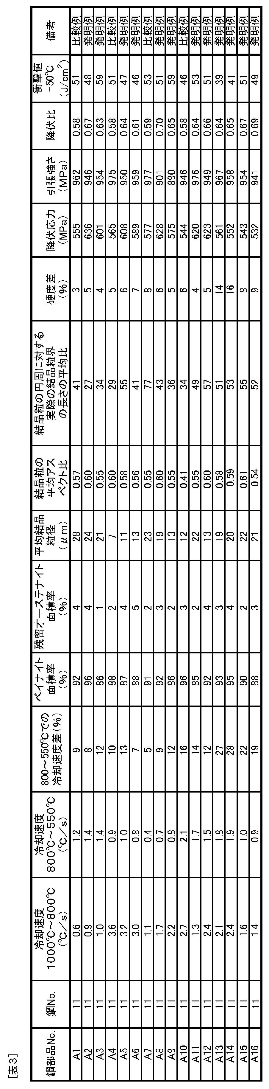
- steel No. shown in Table 1 About a round bar with a diameter of 25 mm obtained by melting steel having a chemical composition of 11 in a vacuum melting furnace, casting a 50 kg steel ingot (steel material), and swaging under the same conditions as in Example 1. , After hot swaging, cooling was performed under various cooling rate conditions shown in Table 3 to obtain steel parts. Some of the round bars (steel part Nos. A13, A14, A15 and A16) had a diameter of 30 mm at the tip length of 150 mm. That is, in order to simulate the case where the part has a complicated shape and investigate the effect of the cooling rate difference on the characteristics, the cooling rate difference was intentionally given.
- Example 1 For the steel parts thus obtained, the steel structure, subsurface hardness and mechanical properties were investigated in the same manner as in Example 1, and the results are also shown in Table 3. Here, the cooling rate difference was obtained in the same manner as in Example 1.
- A2, A3, A5, A6, A8, A9, A11, and A12 are invention examples that satisfy the composition of the present invention and the cooling rate conditions after hot forging.
- steel part No. A1 is an example in which the cooling rate from 1000 ° C. to 800 ° C. is below the stipulations of the present invention, the average grain size of bainite exceeds the upper limit of 25 ⁇ m of the range stipulated in the present invention, and is 0.60 or more. This is a comparative example in which a yield ratio was not obtained.
- steel part No. A4 is an example in which the cooling rate from 1000° C. to 800° C. exceeds the specified range of the present invention, and as a result, the average grain size of bainite falls below the lower limit of 10 ⁇ m of the range specified in the present invention.
- This is a comparative example in which a yield ratio of 60 or more was not obtained.
- the average of the ratio of the crystal grain length to the circumference length when the crystal grain is a perfect circle is within the specified range of the present invention. is an example exceeding the upper limit of 60, and is a comparative example in which a yield ratio of 0.60 or more was not obtained.
- Steel part No. A10 is an example in which the average aspect ratio of the crystal grains is less than the lower limit of 0.5 of the range specified in the present invention as a result of the cooling rate from 800 ° C. to 550 ° C. falling below the provisions of this patent, and 0.60 or more. This is a comparative example in which the yield ratio of was not obtained.
- Steel part No. Part of A13, A14, A15, and A16 has a diameter of 30 mm.
- Steel part no. A13 and A14 are cases where the difference in subsurface hardness in the part exceeded 10% due to the cooling rate difference from 800°C to 550°C exceeding 25%.
- steel part No. A15 and A16 are cases where the subsurface hardness difference in the part was suppressed to 10% or less because the cooling rate difference was less than 25%.
Landscapes
- Chemical & Material Sciences (AREA)
- Engineering & Computer Science (AREA)
- Mechanical Engineering (AREA)
- Materials Engineering (AREA)
- Metallurgy (AREA)
- Organic Chemistry (AREA)
- Physics & Mathematics (AREA)
- Thermal Sciences (AREA)
- Crystallography & Structural Chemistry (AREA)
- Heat Treatment Of Steel (AREA)
Abstract
Description
1つ目は、結晶粒径を微細にすることである。結晶粒径が微細であれば、転位源から結晶粒界までの距離が短いため、堆積する転位の量が限定され、転位堆積による応力もその分低く抑えられる。つまり、結晶粒径は基本的に微細である方がよい。
1.質量%で
C: 0.21~0.24%、
Si:0.11~0.25%、
Mn:1.81~1.99%、
P: 0.014~0.025%、
S: 0.035~0.060%、
Cr:0.55~0.65%、
Al:0.010~0.050%、
Ti:0.005~0.020%、
V: 0.15~0.20%および
N: 0.0090~0.0150%
を、以下の(1)式で得られるF1の値が0.65%以上となる範囲にて含み、残部がFeおよび不可避的不純物である成分組成と、ベイナイト組織の面積率が85%以上かつ残留オーステナイトの面積率が5%以下である組織とを有し、
前記ベイナイト組織の結晶粒は、平均径が10μm以上25μm以下、平均アスペクト比が0.5以上、および、結晶粒の円周に対する結晶粒界の長さの平均比が60以下である、鋼部品。
F1=C+Si/24+Mn/6+Ni/40+Cr/5+Mo/4+V/14…(1)
ここで、(1)式中の各元素記号は、当該元素の含有量(質量%)であり、含有されない元素については0としてF1を算出するものとする。
Cu:0.25%以下、
Ni:0.25%以下、
Mo:0.15%以下および
Nb:0.030%以下
のいずれか1種以上を含有する前記1または2に記載の鋼部品。
C(炭素)は、鋼中に固溶または炭化物を形成し、鋼の強度を向上する有益な元素である。ベイナイト組織は微細なセメンタイトが析出した組織であるため、ある程度のCが鋼中に存在しないと、十分な析出強化を得られるだけのセメンタイトが得られず、降伏応力が低くなり降伏比を満足できなくなってしまう。そのため、Cは0.21%以上添加されている必要がある。一方で、過剰に添加すると、転位源であるセメンタイト量が多くなりすぎるため、これも降伏応力を維持できなくなる。このため添加量の上限は0.24%である。
Si(珪素)は、鋼に固溶し、鋼の強度を高めると同時に焼き入れ性を向上し、ベイナイト面積率を上げるのに有益な元素である。これらの効果を得るためには、0.11%以上の添加が必要である。一方で、Siは熱間鍛造のための前加熱時に厚い被膜を形成し、熱間鍛造前のスケール剥離性を劣化させる、有害な効果も有する。これを避けるためには0.25%を超えた添加は避けなければならない。好ましくは、0.13~0.23%である。
Mn(マンガン)は、鋼中に固溶し鋼の強度を上げる、鋼の焼き入れ性を上げる、Sと結合して硫化物を形成し鋼の被削性を向上させる、などの多様な有益効果を有する重要な元素である。それらの効果を得るためには、1.81%以上の添加が必要である。一方で、Mnを過剰に添加すると、残留オーステナイト量が多くなりすぎ、降伏応力を維持できなくなる。このため添加量の上限は1.99%である。好ましくは、1.83~1.97%である。
P(リン)は、鋼中に固溶し鋼の降伏応力を上げる有益な元素である。その効果を得るためには0.014%以上の添加が必要である。一方で、Pは熱間鍛造後のオーステナイトの結晶粒界に偏析し、室温での靭性を悪化させる側面を持つ。これを避けるためPの含有量は0.025%以下とする。好ましくは、0.014~0.022%である。
S(硫黄)は、Mnと結合して鋼中に硫化物を形成し、鋼の被削性を上げる効果を有する有益な元素である。その効果を得るためには、0.035%以上の添加が必要である。一方で、Sを過剰に添加しすぎると、多量のMnSを形成してFe中に固溶するMnの量を低下させMnの有益な効果である強度向上や焼き入れ性向上の効果が削がれるだけでなく、MnSが転位源としても働き、鋼の降伏応力を下げる結果になってしまう。これを避けるために、Sの添加量は0.060%を上限とする。より好ましくは、0.050%未満である。
Cr(クロム)は、鋼中に固溶し鋼の強度を上げる、鋼の焼き入れ性を上げる、などの多様な有益効果を有する重要な元素である。それらの効果を得るためには、0.55%以上の添加が必要である。一方で、Crを過剰に添加すると、残留オーステナイト量が多くなりすぎ、高い降伏応力を維持できなくなる。このため、添加量の上限は0.65%である。
Al(アルミニウム)は、鋼の精練や鋳造時に空気から溶鋼中に不可避的に侵入してくる酸素と結びつき無害化する有益な元素である。Alによる脱酸が十分でなければ鋼中で過剰となった酸素はTiと結びつき、後述のTiの効果が十分に得られなくなってしまう。酸素の無害化のためには、0.010%以上の添加が必要である。一方で、0.050%を超えて添加すると、逆にアルミニウム酸化物自体が鋼中に多量に含まれるようになり、鋼の靭性を悪化させるため、これを超えた添加は避けるべきである。好ましくは、0.020~0.045%である。
Ti(チタン)は、鋼中で極めて微細な析出物を形成し、熱間鍛造前後でのオーステナイト粒の粗大化を抑制することで靭性の悪化を防ぐ有益な元素である。その効果を得るためには0.005%以上の添加が必要である。一方で、0.020%を超えて添加すると、熱間鍛造前の加熱時に析出物が粗大化し有益な効果が得られなくなる。従って、0.020%を超えての添加は避ける必要がある。好ましくは、0.006~0.017%である。
V(バナジウム)は、鋼中に固溶し鋼を固溶強化するとともに、鋼の焼き入れ性を上げる有益な元素である。そのような効果を得るためには、0.15%以上の添加が必要である。一方で、VはCと結合し析出物を形成することで鋼の靭性を悪化させる作用も有する。これを避けるために、Vの添加量は0.20%以下とする。好ましくは、0.16~0.19%である。
N(窒素)は、主にTiやVと結合して熱間鍛造前後でのオーステナイト粒の粗大化を抑制することによって、靭性の悪化を防ぐ有益な元素である。その効果を得るためには、0.0090%以上の添加が必要である。一方で、0.0150%を超えて添加すると、常温でひずみ時効(転位のまわりにNが偏析しコットレル雰囲気を形成して転位の易動度を著しく妨げる効果)を発現し、後述の-50℃での衝撃値が著しく低下する。これを避けるためには、Nの添加量の上限は0.0150%とする。好ましくは、0.0095~0.0130%である。
F1=C+Si/24+Mn/6+Ni/40+Cr/5+Mo/4+V/14
ここで、(1)式中の各元素記号は、当該元素の含有量(質量%)であり、含有されない元素については0としてF1を算出するものとする。
ベイナイト組織を得るための最低限の成分規制は、上記の通り、成分の種類と成分毎の添加範囲で行っている。さらに、実際の熱間鍛造後の冷却において冷却速度に幅があるときに得られる機械的特性のロバスト性を高めるために、F1として示す式(1)に従って、添加合金元素バランスも規定する必要がある。このバランスを定める式をF1としたときに、その値は0.65%以上である必要がある。すなわち、上記の値が0.65%未満であると、たとえベイナイト主体の組織が得られたとしても、降伏比で0.60以上となる鋼を得ることが難しくなる。
ここで、不可避的不純物として考えられる元素として、O(酸素)、B(ホウ素)、Mg(マグネシウム)、Ca(カルシウム)、REM(レアアースメタル)などがある。これらいずれの元素にしても、含有量は0.0015%未満である。
Cu(銅)は、鋼中に固溶し鋼を固溶強化する元素であり、強度確保のために添加することができる。Cuを添加する場合は、0.03%以上で添加することが好ましい。しかし、Cuを過度に添加すると、残留オーステナイトを増やし降伏応力が低下する結果、所定の降伏比が得られなくなる。これを避けるためには、その添加の上限を0.25%、より好ましくは0.20%とする。
Ni(ニッケル)は、鋼中に固溶し鋼を固溶強化する元素であり、強度確保のために添加することができる。Niを添加する場合は、0.03%以上で添加することが好ましい。しかし、Niを過度に添加すると、残留オーステナイトを増やし降伏応力が低下する結果、所定の降伏比が得られなくなる。これを避けるためには、その添加の上限を0.25%、より好ましくは0.20%とする。
Mo(モリブデン)は、鋼中に固溶し鋼の強度を上げる、鋼の焼き入れ性を上げる、などの多様な有益効果を有する元素であり、好ましくは0.10%以上で添加することができる。しかし、Moを過剰に添加すると、残留オーステナイト量が多くなりすぎ、降伏応力を維持できなくなる。このために、添加する場合の上限は0.15%である。
Nb(ニオブ)は、鋼中で極めて微細な析出物を形成し、熱間鍛造前後でのオーステナイト粒の粗大化を抑制することで靭性の悪化を防ぐ有益な元素であり、好ましくは0.013%以上で添加することができる。しかし、Nbを過剰に添加すると、熱間圧延において表面疵が多発するようになる。このために、添加する場合の上限は0.030%である。
[ベイナイト組織の面積率:85%以上]
ベイナイト組織は、強度と靭性のバランスが良いため、非調質鋼の組織として適切である。具体的には、ベイナイト組織の鋼であれば、JIS Z2242に定めるシャルピー衝撃試験によって求まる、-50℃での衝撃値が35J/cm2以上となる。すなわち、-50℃での衝撃値が35J/cm2以上であれば、人間が自動車またはトラックやトレーラーなどのヘビーデューティービークルを使用する地球上の環境で想定される使用温度において、十分な靭性を確保することができる。このような特性を得るためには、面積率で85%以上のベイナイト組織が必要である。より好ましくは90%以上である。
[残留オーステナイトの面積率:5%以下]
残留オーステナイトは転位源となり降伏応力を下げる働きをするため、その面積率は低ければ低いほど良く、その上限は5%である。0%であってもよいのは勿論である。
ベイナイト組織の結晶粒径は、変形しづらい結晶粒とするために非常に重要な因子である。ここでいう結晶粒とは、結晶粒界に隣接する結晶粒の結晶方位の角度差が15°以上の傾きを有する結晶粒界に囲まれる結晶粒のことである。また、平均径とは、試験片の任意の観察平面において上記のような結晶粒が20個以上含まれる範囲の視野における、その視野内のすべての結晶粒の径の加重平均値のことである。また、結晶粒の径とは、組織観察断面において観察される結晶粒の形状を真円と仮定したときの、その結晶粒の面積から求まる直径のことである。
変形しづらい結晶粒であるためには結晶粒の形状が真球に近い方がよい。従って、結晶粒のアスペクト比は0.5以上である必要がある。好ましくは、0.55以上である。
ここで、結晶粒のアスペクト比とは、以下のように求める。まず、観察によって得られた結晶粒の重心位置を求める。この重心位置で直交する任意の2本の直線を結晶粒上に引く。なお、Cの字形状のように重心位置が結晶粒面内に無い場合は、求めた重心位置に最も近い結晶粒界上の点を重心位置とする。このようにして引いた任意の2直線の各直線において、結晶粒の周縁と交わる2つの交点の同直線上の離間距離を交点間距離とする。上記の任意の2直線の一方の直線における交点間距離と他方の直線における交点間距離との差が最大となるときの、長い方の交点間距離を最長辺および短い方の交点間距離を最短辺とする。かように特定した、最短辺を最長辺で割った値が、結晶粒のアスペクト比である。また、アスペクト比の平均とは、試験片の任意の観察平面において、結晶粒が20個以上含まれる範囲の視野における、同視野内のすべての結晶粒のアスペクト比の算出平均である。
上記の結晶粒の径、から求まる結晶粒の円周と結晶粒界の長さの比が平均で60以下である必要がある。ここで、結晶粒界の長さとは、後述するEBSDによって測定された結晶粒において、結晶粒界と判定されたピクセル数の合計数を、観察倍率によって長さに換算して求まる結晶粒界の長さのことである。以下、結晶粒の円周に対する結晶粒界の長さの比を、結晶粒界長さの比という。この結晶粒界長さの比の平均化も、試験片の任意の観察平面において結晶粒が20個以上含まれる範囲の視野における、その視野内のすべての結晶粒の結晶粒界長さの比の加重平均である。上述の結晶粒の円周に対する結晶粒界の長さの平均比(以下、結晶粒界長さの平均比ともいう)も、上述の通りEBSDにて求めることができる。そして、この結晶粒界長さの平均比が60を超えると、転位の放出減となる結晶粒界の面積が大きくなりすぎるため、十分な降伏比を得ることが難しくなる。より好ましい結晶粒界長さの平均比は、55以下である。
[((Hv1-Hv2)/Hv1)×100:10%以下]
以上の条件を満足する鋼部品は所望の機械的特性を有するものになる。かくして得られる機械的特性は、各鋼部品において均一であることが好ましい。そのためには、部品表面下の硬さの差((Hv1-Hv2)/Hv1)×100(以下、表面下硬度差ともいう)を10%以下ですることが好ましい。すなわち、部品の変形は表面硬度に律速されるため、表面下硬度差が10%以下であれば、部品としての性能がより均一となる。
なお、表面下硬度差は、後述の実施例における測定手法に従って求めることができる。
すなわち、上記した成分組成に従う鋼を溶製して鋼素材、例えば鋼塊に鋳造したのち、この鋼塊を1150℃以上の温度に加熱、保持してから、所望の部品形状に熱間鍛造する。さらに、この熱間鍛造後の熱間鍛造材に、1000℃から800℃までを0.7℃/s以上3.5℃/s以下、かつ800℃から550℃までを0.5℃/s以上2.0℃/s以下の平均冷却速度にて、冷却を施すことが肝要である。
まず、鋼素材を1150℃以上に加熱する。なぜなら、熱間鍛造時の鍛造性を確保するために、鍛造性を悪化させる析出物である炭化物と窒化物を溶解させるには、1150℃以上に加熱する必要があるからである。上限は特に限定する必要はないが、表面酸化被膜による歩留まり悪化の観点からは、1300℃以下とすることが好ましい。
非調質鋼の部品に所望の強度を与える工程は、熱間鍛造後の部品の冷却過程における、冷却速度が非常に重要である。ここで、熱間鍛造部品の形状は一様ではなく様々であることから、冷却中の部品には冷却速度が遅い部分もあれば逆に早い部分もある。このように一つの部品の中で冷却速度にばらつきが生じるときに、部品全体にわたってある程度一様な特性を冷却過程で得るためには、素材となる非調質用鋼に冷却速度に対するロバスト性がなければならない。そのような観点から、本発明で規定した成分範囲の鋼は1000℃から800℃までの平均冷却速度が0.7℃/s未満になると、ベイナイト変態前の旧オーステナイト粒が粗大となり、結果としてベイナイトの平均結晶粒径が25μmを超えてしまう。従って、1000℃から800℃までの平均冷却速度を0.7℃/s以上とする。好ましくは、0.9℃/s以上、より好ましくは1.0℃/s以上である。
上記の通り、非調質用鋼に冷却速度に対するロバスト性を付与する観点から、1000℃から800℃までの平均冷却速度を0.7℃/s以上3.5℃/s以下の範囲に制御するが、この条件を満足した場合であっても、その後の800℃から550℃までの温度域における平均冷却速度も規定する必要がある。すなわち、800℃から550℃までの平均冷却速度が0.5℃/s未満の場合、上記した結晶粒界長さの平均比が60を超えてしまうことになる。そこで、800℃から550℃までの平均冷却速度を0.5℃/s以上とする。好ましくは0.7℃以上、より好ましくは0.8℃/s以上である。
[((V1-V2)/V1)×100が25%以下]
上述したように、機械的特性は、各鋼部品において均一であること、特に部品の性能としては、組織および硬さが均一であることが好ましい。従って、部品形状が複雑であっても冷却速度をある一定の範囲に収めることが有利である。そのためには、熱間鍛造材における冷却速度差(V1-V2)/V1(以下、冷却速度差ともいう)が25%以下であることが好ましい。冷却速度差が25%以下であれば、組織および硬さの差が小さく、部品の機械的性能がより均一となる。
なお、冷却速度差は、後述の実施例における測定手法に従って求めることができる。


表面下硬度は上記5つの冷却速度測定位置の半径方向断面(いわゆるC断面)のそれぞれにおいて、表面から半径方向へ1mmの位置の周方向任意2箇所、丸棒全体で10箇所を対象に、ビッカース硬度計で硬さを測定した。この測定結果の最大値Hv1と最小値Hv2を用いて、((Hv1-Hv2)/Hv1)×100を算出し、表面下硬度差とした。得られた表面下硬度差は、5つの冷却速度測定位置における最大値として、表2に示す。
すなわち、ベイナイト面積率は、ナイタール溶液により適度にエッチングした観察面の光学顕微鏡写真から点算法により求めた。点算法とは、光学顕微鏡写真上に適度に配置した点の総数のうち、面積率を求めたい組織の上にある点の割合を求める面積率測定方法である。点の大きさや配置方法に特に好ましい条件は無いが、一般的には、組織写真上に等間隔且つ直交するように複数配置した線が交わる点、いわゆる格子点とするのが一般的である。線の太さに規定は無いが、例えばマイクロソフト社のパワーポイント アプリケーションのスライド上で太さが0.5~0.75ptとした線で格子点を構成するのが一般的である。このようにして構成した格子点群を、組織写真上に重ね、上記のようにして求めた面積率を測定したい組織上にあった格子点の数の合計が格子点総数に占める割合を、面積率または体積率と見做すことができる。格子点が組織の境目上に重なっている場合は、0.5個の格子点として数えればよい。そして、このようにして求めたベイナイトの面積率から、後述するEBSDで求めた残留オーステナイト面積率を引いた値を、その鋼部品のベイナイト面積率とした。得られたベイナイト面積率は、5つの冷却速度測定位置における平均値として、表2に示す。
このようにして得られた試験片から、以下の通りに機械的特性を調査した。
以上の測定結果を表2に併記する。


Claims (5)
- 質量%で
C: 0.21~0.24%、
Si:0.11~0.25%、
Mn:1.81~1.99%、
P: 0.014~0.025%、
S: 0.035~0.060%、
Cr:0.55~0.65%、
Al:0.010~0.050%、
Ti:0.005~0.020%、
V: 0.15~0.20%および
N: 0.0090~0.0150%
を、以下の(1)式で得られるF1の値が0.65%以上となる範囲にて含み、残部がFeおよび不可避的不純物である成分組成と、ベイナイト組織の面積率が85%以上かつ残留オーステナイトの面積率が5%以下である組織とを有し、
前記ベイナイト組織の結晶粒は、平均径が10μm以上25μm以下、平均アスペクト比が0.5以上、および、結晶粒の円周に対する結晶粒界の長さの平均比が60以下である、鋼部品。
F1=C+Si/24+Mn/6+Ni/40+Cr/5+Mo/4+V/14…(1)
ここで、(1)式中の各元素記号は、当該元素の含有量(質量%)であり、含有されない元素については0としてF1を算出するものとする。 - 前記鋼部品の表面下1mmにおけるビッカース硬さの最大値Hv1と最小値Hv2との差の最大値Hv1に対する比((Hv1-Hv2)/Hv1)×100が10%以下である、請求項1に記載の鋼部品。
- 前記成分組成は、さらに質量%で
Cu:0.25%以下、
Ni:0.25%以下、
Mo:0.15%以下および
Nb:0.030%以下
のいずれか1種以上を含有する請求項1または2に記載の鋼部品。 - 請求項1または3に記載の成分組成を有する鋼素材を、1150℃以上に加熱・保持後に熱間鍛造を施して熱間鍛造材とし、次いで、前記熱間鍛造材に、1000℃から800℃までを0.7℃/s以上3.5℃/s以下、かつ800℃から550℃までを0.5℃/s以上2.0℃/s以下の平均冷却速度にて、冷却を施す、鋼部品の製造方法。
- 前記800℃から550℃までの冷却は、前記熱間鍛造材における冷却速度分布の最高値V1と最低値V2との差の最大値V1に対する比((V1-V2)/V1)×100が25%以下にて行う、請求項4に記載の鋼部品の製造方法。
Priority Applications (5)
| Application Number | Priority Date | Filing Date | Title |
|---|---|---|---|
| KR1020247022086A KR20240118819A (ko) | 2022-01-28 | 2023-01-26 | 강 부품 및 그 제조 방법 |
| JP2023535787A JP7380957B1 (ja) | 2022-01-28 | 2023-01-26 | 鋼部品およびその製造方法 |
| US18/727,884 US20250230530A1 (en) | 2022-01-28 | 2023-01-26 | Steel component and method of producing same |
| CN202380017976.7A CN118591647A (zh) | 2022-01-28 | 2023-01-26 | 钢部件及其制造方法 |
| EP23747048.9A EP4464810A4 (en) | 2022-01-28 | 2023-01-26 | STEEL COMPONENT AND ITS PRODUCTION PROCESS |
Applications Claiming Priority (2)
| Application Number | Priority Date | Filing Date | Title |
|---|---|---|---|
| JP2022012396 | 2022-01-28 | ||
| JP2022-012396 | 2022-01-28 |
Publications (1)
| Publication Number | Publication Date |
|---|---|
| WO2023145838A1 true WO2023145838A1 (ja) | 2023-08-03 |
Family
ID=87471532
Family Applications (1)
| Application Number | Title | Priority Date | Filing Date |
|---|---|---|---|
| PCT/JP2023/002508 Ceased WO2023145838A1 (ja) | 2022-01-28 | 2023-01-26 | 鋼部品およびその製造方法 |
Country Status (6)
| Country | Link |
|---|---|
| US (1) | US20250230530A1 (ja) |
| EP (1) | EP4464810A4 (ja) |
| JP (1) | JP7380957B1 (ja) |
| KR (1) | KR20240118819A (ja) |
| CN (1) | CN118591647A (ja) |
| WO (1) | WO2023145838A1 (ja) |
Families Citing this family (3)
| Publication number | Priority date | Publication date | Assignee | Title |
|---|---|---|---|---|
| KR102705357B1 (ko) | 2019-12-23 | 2024-09-09 | 제이에프이 스틸 가부시키가이샤 | 쾌삭강 및 그의 제조 방법 |
| JP7024921B1 (ja) * | 2020-03-31 | 2022-02-24 | Jfeスチール株式会社 | 快削鋼およびその製造方法 |
| US12562415B1 (en) | 2024-10-29 | 2026-02-24 | Sumitomo Riko Company Limited | Thermal insulation sheet between battery cells for electric automobile |
Citations (5)
| Publication number | Priority date | Publication date | Assignee | Title |
|---|---|---|---|---|
| JPH05279788A (ja) * | 1992-03-31 | 1993-10-26 | Sumitomo Metal Ind Ltd | 強度および靱性に優れた熱間鍛造用非調質鋼 |
| JPH09111412A (ja) * | 1995-10-19 | 1997-04-28 | Sumitomo Metal Ind Ltd | 高強度・高降伏比・低延性非調質鋼 |
| KR20040037738A (ko) * | 2002-10-30 | 2004-05-07 | 현대자동차주식회사 | 고강도 고인성 로워 암 커넥터 제조방법 |
| KR20140056767A (ko) * | 2012-10-31 | 2014-05-12 | 현대제철 주식회사 | 액슬빔 및 그 제조 방법 |
| WO2018155610A1 (ja) * | 2017-02-24 | 2018-08-30 | 新日鐵住金株式会社 | 熱間鍛造用棒鋼 |
Family Cites Families (7)
| Publication number | Priority date | Publication date | Assignee | Title |
|---|---|---|---|---|
| JPH04285118A (ja) | 1991-03-13 | 1992-10-09 | Nippon Steel Corp | 高強度高靭性熱間鍛造非調質鋼の製造方法 |
| JP3339587B2 (ja) | 1991-12-04 | 2002-10-28 | 愛知製鋼株式会社 | 熱間鍛造用焼入省略鋼の製造方法 |
| JPH05287373A (ja) | 1992-04-14 | 1993-11-02 | Nippon Steel Corp | 高強度高靱性熱間加工非調質鋼の製造方法 |
| JPH10298703A (ja) | 1997-04-21 | 1998-11-10 | Mitsubishi Seiko Muroran Tokushuko Kk | 降伏比、耐久比に優れたベイナイト型高強度高靭性熱間鍛造用非調質鋼 |
| JP2001200332A (ja) | 2000-01-21 | 2001-07-24 | Sanyo Special Steel Co Ltd | 高靱性非調質鋼 |
| US20140283954A1 (en) * | 2013-03-22 | 2014-09-25 | Caterpiller Inc. | Bainitic microalloy steel with enhanced nitriding characteristics |
| ES2733805T3 (es) * | 2015-11-16 | 2019-12-03 | Deutsche Edelstahlwerke Specialty Steel Gmbh & Co Kg | Acero fino estructural con estructura bainitica, pieza forjada fabricada a partir del mismo y procedimiento para fabricar una pieza forjada |
-
2023
- 2023-01-26 EP EP23747048.9A patent/EP4464810A4/en active Pending
- 2023-01-26 WO PCT/JP2023/002508 patent/WO2023145838A1/ja not_active Ceased
- 2023-01-26 KR KR1020247022086A patent/KR20240118819A/ko active Pending
- 2023-01-26 JP JP2023535787A patent/JP7380957B1/ja active Active
- 2023-01-26 CN CN202380017976.7A patent/CN118591647A/zh active Pending
- 2023-01-26 US US18/727,884 patent/US20250230530A1/en active Pending
Patent Citations (5)
| Publication number | Priority date | Publication date | Assignee | Title |
|---|---|---|---|---|
| JPH05279788A (ja) * | 1992-03-31 | 1993-10-26 | Sumitomo Metal Ind Ltd | 強度および靱性に優れた熱間鍛造用非調質鋼 |
| JPH09111412A (ja) * | 1995-10-19 | 1997-04-28 | Sumitomo Metal Ind Ltd | 高強度・高降伏比・低延性非調質鋼 |
| KR20040037738A (ko) * | 2002-10-30 | 2004-05-07 | 현대자동차주식회사 | 고강도 고인성 로워 암 커넥터 제조방법 |
| KR20140056767A (ko) * | 2012-10-31 | 2014-05-12 | 현대제철 주식회사 | 액슬빔 및 그 제조 방법 |
| WO2018155610A1 (ja) * | 2017-02-24 | 2018-08-30 | 新日鐵住金株式会社 | 熱間鍛造用棒鋼 |
Non-Patent Citations (1)
| Title |
|---|
| See also references of EP4464810A4 * |
Also Published As
| Publication number | Publication date |
|---|---|
| US20250230530A1 (en) | 2025-07-17 |
| EP4464810A4 (en) | 2025-11-19 |
| KR20240118819A (ko) | 2024-08-05 |
| CN118591647A (zh) | 2024-09-03 |
| EP4464810A1 (en) | 2024-11-20 |
| JPWO2023145838A1 (ja) | 2023-08-03 |
| JP7380957B1 (ja) | 2023-11-15 |
Similar Documents
| Publication | Publication Date | Title |
|---|---|---|
| JP7654559B2 (ja) | 高硬度鋼材およびその製造方法 | |
| KR101367350B1 (ko) | 냉간 가공성, 절삭성, 침탄 담금질 후의 피로 특성이 우수한 표면 경화 강 및 그 제조 방법 | |
| JP7380957B1 (ja) | 鋼部品およびその製造方法 | |
| JP4709944B2 (ja) | 肌焼鋼、浸炭部品、及び肌焼鋼の製造方法 | |
| JP5778055B2 (ja) | 熱間鍛造用圧延棒鋼および熱間鍛造素形材ならびにコモンレールおよびその製造方法 | |
| JP5736936B2 (ja) | 熱間圧延棒鋼または線材、および冷間鍛造用鋼線の製造方法 | |
| JP7697499B2 (ja) | 鋼部品およびその製造方法 | |
| JP7018510B2 (ja) | 優れた硬度と衝撃靭性を有する耐摩耗鋼及びその製造方法 | |
| WO2015029553A1 (ja) | ステアリングラックバー用圧延丸鋼材およびステアリングラックバー | |
| WO2014132968A1 (ja) | 焼き付け硬化性と低温靭性に優れた引張最大強度980MPa以上の高強度熱延鋼板 | |
| JPWO2017022025A1 (ja) | 高強度熱延鋼板 | |
| EP3385400A1 (en) | Rolling rod for cold-forged thermally refined article | |
| CN105189801A (zh) | 不锈钢板 | |
| JP6819198B2 (ja) | 冷間鍛造調質品用圧延棒線 | |
| WO2021254719A1 (en) | High strength steel product and method of manufacturing the same | |
| JPWO2019198415A1 (ja) | 浸炭処理が行われる部品用の鋼材 | |
| CN107371369A (zh) | 具有高强度特性的具有贝氏体组织的部件和制造方法 | |
| JPWO2018061101A1 (ja) | 鋼 | |
| JP5799917B2 (ja) | 熱間圧延棒鋼または線材 | |
| EP3859028A1 (en) | Railway wheel | |
| US20180094345A1 (en) | Case-hardened steel component | |
| US12276005B2 (en) | Steel shaft component | |
| JP5489497B2 (ja) | 焼入性に優れたボロン鋼鋼板の製造方法 | |
| JP5601861B2 (ja) | ボロン鋼圧延焼鈍鋼板の製造法 | |
| JP7705065B2 (ja) | 熱延鋼板 |
Legal Events
| Date | Code | Title | Description |
|---|---|---|---|
| WWE | Wipo information: entry into national phase |
Ref document number: 2023535787 Country of ref document: JP |
|
| 121 | Ep: the epo has been informed by wipo that ep was designated in this application |
Ref document number: 23747048 Country of ref document: EP Kind code of ref document: A1 |
|
| ENP | Entry into the national phase |
Ref document number: 20247022086 Country of ref document: KR Kind code of ref document: A |
|
| WWE | Wipo information: entry into national phase |
Ref document number: 18727884 Country of ref document: US |
|
| WWE | Wipo information: entry into national phase |
Ref document number: 202380017976.7 Country of ref document: CN |
|
| WWE | Wipo information: entry into national phase |
Ref document number: 202417056314 Country of ref document: IN |
|
| WWE | Wipo information: entry into national phase |
Ref document number: 2023747048 Country of ref document: EP |
|
| ENP | Entry into the national phase |
Ref document number: 2023747048 Country of ref document: EP Effective date: 20240813 |
|
| NENP | Non-entry into the national phase |
Ref country code: DE |
|
| WWP | Wipo information: published in national office |
Ref document number: 18727884 Country of ref document: US |