WO2023157295A1 - Dispositif d'estimation de qualité de réseau, procédé d'estimation de qualité de réseau et programme - Google Patents
Dispositif d'estimation de qualité de réseau, procédé d'estimation de qualité de réseau et programme Download PDFInfo
- Publication number
- WO2023157295A1 WO2023157295A1 PCT/JP2022/006948 JP2022006948W WO2023157295A1 WO 2023157295 A1 WO2023157295 A1 WO 2023157295A1 JP 2022006948 W JP2022006948 W JP 2022006948W WO 2023157295 A1 WO2023157295 A1 WO 2023157295A1
- Authority
- WO
- WIPO (PCT)
- Prior art keywords
- network quality
- time
- series data
- qos
- learning
- Prior art date
- Legal status (The legal status is an assumption and is not a legal conclusion. Google has not performed a legal analysis and makes no representation as to the accuracy of the status listed.)
- Ceased
Links
Images






Classifications
-
- H—ELECTRICITY
- H04—ELECTRIC COMMUNICATION TECHNIQUE
- H04L—TRANSMISSION OF DIGITAL INFORMATION, e.g. TELEGRAPHIC COMMUNICATION
- H04L41/00—Arrangements for maintenance, administration or management of data switching networks, e.g. of packet switching networks
- H04L41/16—Arrangements for maintenance, administration or management of data switching networks, e.g. of packet switching networks using machine learning or artificial intelligence
Definitions
- the present invention relates to a network quality estimation device, a network quality estimation method and a program.
- QoE Quality of Experience
- QoS Quality of Service
- Network control commonly used in commercial networks includes routing protocols such as RIP and OSPF. These protocols calculate a detour route when communication becomes impossible, but do not have the function of changing the route to satisfy the QoS condition in consideration of network congestion.
- RIP RIP
- OSPF OSPF
- the present invention has been made in view of the above points, and aims to contribute to highly feasible estimation of network quality while increasing user satisfaction.
- the network quality estimation device includes a conversion unit configured to convert a request regarding the quality of experience of a user using a network service into a first network quality, 2, time-series data that does not satisfy the first network quality in a front portion and satisfies the first network quality in a rear portion from among a plurality of time-series data relating to network quality of 2. and the time-series data extracted by the extraction unit, the third network quality at a certain time is input, and the time-series data of the fourth network quality targeted in the period after the time a learning unit configured to train a model that outputs
- FIG. 1 is a diagram showing a hardware configuration example of a QoS condition estimation device 10 according to an embodiment of the present invention
- FIG. 3 is a diagram showing an example of the functional configuration of a target QoS estimation device 10a
- FIG. 4 is a diagram showing a configuration example of QoS states
- FIG. 4 is a diagram showing a configuration example of QoS time-series data
- 2 is a diagram showing an example of the functional configuration of a target QoS learning device 10b
- FIG. FIG. 4 is a diagram showing an example of a quantization criterion for QoS values
- 4 is a flowchart for explaining an example of a procedure of estimation processing executed by the target QoS estimation device 10a
- FIG. 3 is a diagram showing an example of the functional configuration of a target QoS estimation device 10a
- FIG. 4 is a diagram showing a configuration example of QoS states
- FIG. 4 is a diagram showing a configuration example of QoS time-series data
- FIG. 4 is a diagram showing an example of quantized QoS time-series data
- FIG. 10 is a diagram showing an example of data after One-hot Encoding
- 6 is a flow chart for explaining an example of a processing procedure executed by a satisfaction level requirement conversion unit 13; , and shows a correspondence table for converting intent ID to network quality.
- 4 is a flowchart for explaining an example of a processing procedure executed by a filtering unit 14
- 5 is a flowchart for explaining an example of a processing procedure executed by a learning data shaping unit 15
- 4 is a flowchart for explaining an example of a processing procedure executed by a learning unit 16;
- QoS Quality of Service
- network quality such as network delay, packet loss, and jitter.
- a machine learning method is used as a means for achieving versatility that does not depend on the nature of a specific service, and in order to respond to various service usage conditions, machine learning input and output is time-series data.
- time-series data As data representing the usage of a service, in addition to information on how many users use the service and where, time-series data that includes information on when each user starts and ends using the service is used. handle.
- LSTM which is a time-series learning method for neural networks. Furthermore, based on the Seq2Seq approach of learning time-series data and predicting time-series data using LSTM, the realizable target QoS for achieving the satisfaction request from the time series representing the current QoS situation It is characterized by having a device for estimating a time series.
- FIG. 1 is a diagram showing a hardware configuration example of the QoS condition estimation device 10 according to the embodiment of the present invention.
- the QoS condition estimating device 10 of FIG. 1 has a drive device 100, an auxiliary storage device 102, a memory device 103, a processor 104, an interface device 105, etc., which are interconnected by a bus B, respectively.
- a program that implements processing in the QoS condition estimation device 10 is provided by a recording medium 101 such as a CD-ROM.
- a recording medium 101 such as a CD-ROM.
- the program is installed from the recording medium 101 to the auxiliary storage device 102 via the drive device 100 .
- the program does not necessarily need to be installed from the recording medium 101, and may be downloaded from another computer via the network.
- the auxiliary storage device 102 stores installed programs, as well as necessary files and data.
- the memory device 103 reads and stores the program from the auxiliary storage device 102 when a program activation instruction is received.
- Processor 104 is a CPU or GPU (Graphics Processing Unit), or CPU and GPU, and executes functions related to QoS condition estimation device 10 according to a program stored in memory device 103 .
- the interface device 105 is used as an interface for connecting to a network.
- the QoS condition estimation device 10 executes an estimation process of estimating the target QoS and a learning process of learning parameters used in the estimation process.
- the QoS condition estimating device 10 when executing the estimation process will be referred to as the "target QoS estimating device 10a”
- the QoS condition estimating device 10 when executing the learning process will be referred to as the "target QoS learning device 10b”.
- the target QoS estimation device 10a and the target QoS learning device 10b may be implemented using different computers.
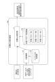
- FIG. 2 is a diagram showing a functional configuration example of the target QoS estimation device 10a.
- a target QoS estimating device 10a includes a target QoS estimating unit 11 and an ID converting unit 12 in order to satisfy a network service user's satisfaction request (intent) and estimate a target QoS that can be achieved in network control.
- tent network service user's satisfaction request
- Each of these units is implemented by processing that one or more programs installed in the target QoS estimation device 10a cause the processor 104 to execute.
- the target QoS estimation device 10 a also uses the intent ID storage unit 121 and the learning parameter storage unit 122 .
- Each of these storage units can be implemented using, for example, the auxiliary storage device 102 or a storage device or the like that can be connected to the target QoS estimation device 10a via a network.
- the target QoS estimating unit 11 inputs the “current QoS situation”, and among the parameters (learning parameters) obtained by machine learning stored in the learning parameter storage unit 122, the learning parameter corresponding to the input intent is calculated. is used to estimate the target QoS in the period after the present and output the target QoS.
- the input data "current QoS status" is, for example, time-series data of observed values of QoS indicators such as delay, packet loss, and jitter from the current time to a certain past time.
- the types of QoS indices are defined as q1, q2, . . . qk. k is the number of types of QoS indicators.
- edge routers that bundle users having some commonality such as connecting regions are defined as zones z1, z2, ... zi.
- services such as video distribution and web conferences used in each zone zi are defined as s1, s2, . . . sj. Assuming that each service uses a server and each zone zi communicates with the server of each service sj on the network, i ⁇ j ⁇ k QoS information is required per hour.
- the time-series data representing the "current QoS status" is time-series data of the QoS status with a predetermined length L_in.
- the time-series data of the QoS status is hereinafter referred to as "QoS time-series data".
- FIG. 4 shows an example of QoS time-series data with delay as an example.
- the output data from the target QoS estimating unit 11 is QoS time series data with a predetermined length L_out.
- the ID conversion unit 12 receives as input a network service user satisfaction request (intent), and outputs an ID corresponding to the intent (hereinafter referred to as "intent ID").
- An intent is a request regarding a user's QoE (Quality of Experience) when using a network service, which is set by a network service provider in order to guarantee a certain level of user satisfaction.
- Intents are generally given for each service, and there are various forms of expression for the intents. For example, in a video distribution service, there is a satisfaction level requirement such that a video QoE evaluation of 5 and an audio QoE evaluation of 4 are required.
- An intent ID is assigned to each intent as A, B, C, .
- the learning parameter storage unit 122 stores learning parameters learned under the intent ID for each intent of the intent ID output by the ID conversion unit 12 .
- the target QoS estimation unit 11 uses the learning parameter corresponding to the intent ID output by the ID conversion unit 12 to estimate the target QoS.
- the target QoS estimation unit 11 inputs QoS time-series data actually measured from (current time-L_in) to the current time and the ID of the intent output by the ID conversion unit 12, and Output QoS time-series data of (current time + L_out).
- the output QoS time-series data becomes the QoS control target for satisfying the input intent (satisfaction level request).
- FIG. 5 is a diagram showing a functional configuration example of the target QoS learning device 10b.
- the target QoS learning device 10b has an ID converter 12, a satisfaction request converter 13, a filtering unit 14, a learning data shaping unit 15, and a learning unit 16.
- FIG. Each of these units is implemented by processing that one or more programs installed in the target QoS learning device 10b cause the processor 104 to execute.
- the target QoS learning device 10 b also uses an intent ID storage unit 121 , a past QoS time-series data storage unit 123 and a learning parameter storage unit 122 .
- Each of these storage units can be implemented using, for example, the auxiliary storage device 102 or a storage device or the like that can be connected to the target QoS learning device 10b via a network.
- the satisfaction request conversion unit 13 converts the intent ID output by the ID conversion unit 12 into network quality (QoS conditions) corresponding to the intent (satisfaction request) associated with the intent ID.
- QoS conditions network quality
- the filtering unit 14 inputs a plurality of QoS time-series data observed in the past stored in the past QoS time-series data storage unit 123, and outputs QoS time-series data suitable for learning.
- Past QoS time-series data as input data is QoS time-series data of length L_in+L_out.
- the learning data shaping unit 15 divides QoS time-series data of length L (L_in+L_out) into a front part or first half (data up to L_in counting from the front) and a rear part or latter half (L_out counting from the back). data up to the second).
- the first half is used as input data to the learning device of the learning unit 16, and the second half is used as label data for the learning device.
- the QoS value is quantized into n steps for each service according to a predetermined rule according to the given intent ID (output by the ID conversion unit 12) before being input to the learner. .
- FIG. 6 is a diagram showing an example of quantization criteria for QoS values.
- a quantization criteria are shown.
- the QoS condition threshold that satisfies the intent of the given intent ID is used as the threshold for quantization.
- the learning unit 16 receives time-series data, learns the learning parameters of the learning device based on the time-series data, and stores the learned learning parameters in the learning parameter storage unit 122 .
- a Seq2Seq model is used for the learner.
- Seq2Seq is a learning model that receives time-series data as learning data and outputs time-series data corresponding to the learning data.
- Seq2Seq is a model in which English sentences (time-series data with words as elements) are input, and corresponding Japanese sentences are output for translation.
- a learning parameter is learned for each intent ID.
- the learned learning parameters are stored in the learning parameter storage unit 122 as learning parameters A, B, C, . . . for each intent ID (A, B, C, . . . ). That is, each learning parameter is stored associated with an intent ID.
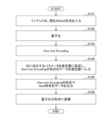
- FIG. 7 is a flowchart for explaining an example of the estimation process performed by the target QoS estimation device 10a.
- step S101 the target QoS estimating unit 11 inputs the intent ID corresponding to the network service user's satisfaction request and the time-series data from time 1 to L_in indicating the current QoS status.
- the intent ID the output from the ID conversion unit 12 that has input the intent is input.
- the target QoS estimation unit 11 quantizes the current QoS situation based on the criteria shown in FIG. 6 (S102).
- FIG. 8 shows an example of quantized QoS time series data.
- the target QoS estimation unit 11 uses One-hot Encoding to set only one element to 1 for each row (time) of the matrix representation of the quantized QoS time-series data (see FIG. M4), and the other Convert to a one-hot vector whose elements are 0 (S103).
- the number of elements of the One-hot vector is the number of all values that one row of the quantized QoS time-series data can take.
- Each element corresponds to one of all values that one row of the quantized QoS time-series data can take, and the values corresponding to each element are different from each other.
- the one-hot vector converted from the value of a certain row the element corresponding to the value indicated by the row becomes 1, and the other elements become 0.
- One-hot Encoding is detailed in, for example, ⁇ Francois Chollet (2016), Deep Learning with Python and Keras, pp.190-192, Mynavi Publishing''.
- FIG. 9 is a diagram showing an example of data after One-hot Encoding. Since there are n values that one element can take in the matrix representation of the quantized QoS time-series data, one row containing j ⁇ i elements can have n j ⁇ i values. . Therefore, the size (row, column) of the matrix indicated by the data after One-hot Encoding is (L_in, n j ⁇ i , k).
- the target QoS estimation unit 11 acquires the learning parameter corresponding to the intent ID input in step S101 from the learning parameter storage unit 122, sets it in the estimator, and estimates the data after One-hot encoding. input to the device (S104).
- An estimator is a learned learner (Seq2Seq).
- the estimator outputs the QoS time-series data, which is the future control target, in the same One-hot Encoding format as the input to the estimator. (S105) That is, the QoS condition (target QoS) that will be the future control target is estimated.
- the target QoS estimation unit 11 converts the time-series data in the One-hot Encoding expression format output in step S105 into data in the quantization expression format (S105).
- This conversion result is a time series of target QoS that can be achieved by network control to achieve the intent associated with the input intent ID.
- FIG. 10 is a flow chart for explaining an example of a processing procedure executed by the satisfaction level request conversion unit 13. As shown in FIG.
- step S201 the satisfaction request conversion unit 13 receives the intent ID output from the ID conversion unit 12 that has received the network service user's satisfaction request (intent).
- the satisfaction request conversion unit 13 converts the input intent ID into network quality (QoS conditions) for satisfying the satisfaction request corresponding to the intent ID for each combination of QoS index qk and service sj. ) (S202).
- FIG. 11 is a diagram showing a correspondence table for converting intent IDs into network quality.
- FIG. 11 shows an example of a correspondence table for converting intent IDs into network quality (QoS conditions) for delay, which is one of QoS indicators.
- the network quality required to achieve each QoE is indicated by the range for each service.
- an intent has an expression format such as "QoE of service 1>4 and QoE of service 2>3". Therefore, the satisfaction request conversion unit 13 can convert the intent ID related to the intent into network quality using the correspondence table shown in FIG.
- the satisfaction level request conversion unit 13 outputs the converted network quality (S203).
- FIG. 12 is a flowchart for explaining an example of a processing procedure executed by the filtering unit 14.
- FIG. 12 is a flowchart for explaining an example of a processing procedure executed by the filtering unit 14.
- step S301 the filtering unit 14 receives the network quality (QoS conditions) output by the satisfaction level request conversion unit 13.
- variable l is a variable for storing the number of QoS time-series data extracted as learning data from the QoS time-series data group stored in the past QoS time-series data storage unit 123 .
- a sufficient number of sample data of QoS time-series data observed in the past are stored in the past QoS time-series data storage unit 123 .
- the filtering unit 14 acquires one piece of unprocessed QoS time-series data from the past QoS time-series data storage unit 123 (S303).
- the length of the QoS time-series data is L (L_in+L_out).
- the T-th data counted from the beginning is called time T.
- the filtering unit 14 determines that the acquired QoS time-series data (hereinafter referred to as “target QoS time-series data”) is a It is determined whether or not the input network quality (QoS condition) is satisfied at all times (S304). If the target QoS time-series data satisfies the network quality at all the times (No in S304), the filtering unit 14 determines that the target QoS time-series data is not a learning target, and uses the target QoS time-series data as Discard and return to step S303.
- target QoS time-series data the acquired QoS time-series data
- the filtering unit 14 adds the target QoS time-series data to the learning data (S306).
- the filtering unit 14 adds 1 to l.
- the filtering unit 14 repeats step S303 and subsequent steps until l becomes equal to N.
- N is a predetermined required number of samples.
- N pieces of QoS time-series data are extracted as learning data.
- FIG. 13 is a flowchart for explaining an example of a processing procedure executed by the learning data shaping section 15.
- step S401 the learning data shaping unit 15 inputs the N pieces of QoS time series data extracted by the filtering unit 14.
- the learning data shaping unit 15 executes quantization processing for each input QoS time-series data (S402).
- the quantization processing procedure is as described above.
- the learning data shaping unit 15 converts each quantized QoS time-series data into a matrix in which only one element in each row (each time) is 1 and the other elements are 0 by One-hot Encoding. Convert (S403).
- the size (row, column) of the matrix representing each QoS time-series data is (L, n j ⁇ i , k).
- the size of the matrix representing the input data is (L_in, njxi , k), and the size of the matrix representing the label data is (L_out, njxi , k).
- FIG. 14 is a flowchart for explaining an example of a processing procedure executed by the learning unit 16.
- step S501 the learning unit 16 inputs the intent ID output by the ID conversion unit 12 and the N pieces of learning data (sets of input data and label data) generated by the learning data shaping unit 15.
- the learning unit 16 learns the learning device (Seq2Seq) based on the N pieces of learning data (S502). At this time, the learning unit 16 inputs the input data of the learning data to the learning device for each learning data, and updates the learning parameter of the learning device so that the output from the learning device approaches the output data of the learning data ( learn.
- the learning unit 16 stores the learning parameters of the learning device at that time in the learning parameter storage unit 122 in association with the intent ID input in step S501 (S503).
- the present embodiment it is possible to estimate a controllable target value while satisfying the user's satisfaction request (intent) and considering various network conditions. That is, it is possible to contribute to estimation of network quality with high feasibility while increasing user satisfaction. As a result, for example, setting an unrealizable control target and searching for useless control can be avoided, and improvement in control efficiency can be expected.
- the QoS condition estimation device 10 is an example of a network quality estimation device.
- the filtering unit 14 is an example of an extraction unit.
- the target QoS estimator 11 is an example of an estimator.
Landscapes
- Engineering & Computer Science (AREA)
- Artificial Intelligence (AREA)
- Computer Vision & Pattern Recognition (AREA)
- Databases & Information Systems (AREA)
- Evolutionary Computation (AREA)
- Medical Informatics (AREA)
- Software Systems (AREA)
- Computer Networks & Wireless Communication (AREA)
- Signal Processing (AREA)
- Data Exchanges In Wide-Area Networks (AREA)
Abstract
L'invention concerne un dispositif d'estimation de qualité de réseau qui contribue à estimer une qualité de réseau hautement faisable tout en augmentant une évaluation de satisfaction d'utilisateur en ayant : une unité de conversion configurée de façon à convertir une demande se rapportant à la qualité d'expérience d'un utilisateur à l'aide d'un service de réseau à une première qualité de réseau ; une unité d'extraction configurée de façon à extraire, d'une pluralité de données de séries chronologiques se rapportant à une deuxième qualité de réseau qui a été observée dans le passé, des données de séries chronologiques qui ne satisfont pas la première qualité de réseau dans une partie antérieure et qui satisfont la première qualité de réseau dans une partie ultérieure ; et une unité d'apprentissage configurée de façon à former, à l'aide des données de séries chronologiques extraites par l'unité d'extraction, un modèle qui accepte une troisième qualité de réseau à un instant donné en tant qu'entrée et qui délivre en sortie des données de séries chronologiques d'une quatrième qualité de réseau souhaitée pendant une période après l'instant donné.
Priority Applications (1)
| Application Number | Priority Date | Filing Date | Title |
|---|---|---|---|
| PCT/JP2022/006948 WO2023157295A1 (fr) | 2022-02-21 | 2022-02-21 | Dispositif d'estimation de qualité de réseau, procédé d'estimation de qualité de réseau et programme |
Applications Claiming Priority (1)
| Application Number | Priority Date | Filing Date | Title |
|---|---|---|---|
| PCT/JP2022/006948 WO2023157295A1 (fr) | 2022-02-21 | 2022-02-21 | Dispositif d'estimation de qualité de réseau, procédé d'estimation de qualité de réseau et programme |
Publications (1)
| Publication Number | Publication Date |
|---|---|
| WO2023157295A1 true WO2023157295A1 (fr) | 2023-08-24 |
Family
ID=87578194
Family Applications (1)
| Application Number | Title | Priority Date | Filing Date |
|---|---|---|---|
| PCT/JP2022/006948 Ceased WO2023157295A1 (fr) | 2022-02-21 | 2022-02-21 | Dispositif d'estimation de qualité de réseau, procédé d'estimation de qualité de réseau et programme |
Country Status (1)
| Country | Link |
|---|---|
| WO (1) | WO2023157295A1 (fr) |
Citations (5)
| Publication number | Priority date | Publication date | Assignee | Title |
|---|---|---|---|---|
| JP2019522422A (ja) * | 2016-06-21 | 2019-08-08 | アルカテル・ルーセント | ネットワーク体感品質の評価を自動化するための方法およびシステム |
| CN110166305A (zh) * | 2019-06-04 | 2019-08-23 | 电子科技大学 | 一种基于意图的应用QoE管理方法及系统 |
| WO2021001958A1 (fr) * | 2019-07-03 | 2021-01-07 | 日本電信電話株式会社 | Dispositif de commande de qualité de service, procédé de commande de qualité de service, et programme |
| US20210314238A1 (en) * | 2020-04-07 | 2021-10-07 | Assia Spe, Llc | Systems and methods for remote collaboration |
| US20210337555A1 (en) * | 2018-09-07 | 2021-10-28 | NEC Laboratories Europe GmbH | System and method for network automation in slice-based network using reinforcement learning |
-
2022
- 2022-02-21 WO PCT/JP2022/006948 patent/WO2023157295A1/fr not_active Ceased
Patent Citations (5)
| Publication number | Priority date | Publication date | Assignee | Title |
|---|---|---|---|---|
| JP2019522422A (ja) * | 2016-06-21 | 2019-08-08 | アルカテル・ルーセント | ネットワーク体感品質の評価を自動化するための方法およびシステム |
| US20210337555A1 (en) * | 2018-09-07 | 2021-10-28 | NEC Laboratories Europe GmbH | System and method for network automation in slice-based network using reinforcement learning |
| CN110166305A (zh) * | 2019-06-04 | 2019-08-23 | 电子科技大学 | 一种基于意图的应用QoE管理方法及系统 |
| WO2021001958A1 (fr) * | 2019-07-03 | 2021-01-07 | 日本電信電話株式会社 | Dispositif de commande de qualité de service, procédé de commande de qualité de service, et programme |
| US20210314238A1 (en) * | 2020-04-07 | 2021-10-07 | Assia Spe, Llc | Systems and methods for remote collaboration |
Non-Patent Citations (1)
| Title |
|---|
| DINAKI ET AL.: "Forecasting Video QoE With Deep Learning From Multivariate Time- Series", IEEE OPEN JOURNAL OF SIGNAL PROCESSING, vol. 2, 26 July 2021 (2021-07-26), pages 512 - 521, XP011880161, Retrieved from the Internet <URL:https://ieeexplore.ieee.org/document/9495207> DOI: 10.1109/OJSP.2021.3099065 * |
Similar Documents
| Publication | Publication Date | Title |
|---|---|---|
| US11068655B2 (en) | Text recognition based on training of models at a plurality of training nodes | |
| US11411865B2 (en) | Network resource scheduling method, apparatus, electronic device and storage medium | |
| JP6572245B2 (ja) | 体感品質最適化システム、体感品質最適化装置、レコメンド要求装置、体感品質最適化方法、レコメンド要求方法及びプログラム | |
| US8547851B1 (en) | System and method for reporting traffic information for a network | |
| KR20220053658A (ko) | 데이터 스트림 분류 방법 및 관련 장치 | |
| JP2017097807A (ja) | 学習方法、学習プログラムおよび情報処理装置 | |
| CN117499297B (zh) | 数据包传输路径的筛选方法及装置 | |
| Alt et al. | CBA: Contextual quality adaptation for adaptive bitrate video streaming | |
| US11729106B2 (en) | Service quality control device, method, and program | |
| Naresh et al. | Ppo-abr: Proximal policy optimization based deep reinforcement learning for adaptive bitrate streaming | |
| CN112543145A (zh) | 发送数据的设备节点通信路径选择方法及装置 | |
| CN114866790A (zh) | 直播流调度方法及装置 | |
| JP6660283B2 (ja) | トラヒック需要予測装置、トラヒック需要予測方法、及びプログラム | |
| CN113271253B (zh) | 一种路径确定方法及其相关设备 | |
| WO2023157295A1 (fr) | Dispositif d'estimation de qualité de réseau, procédé d'estimation de qualité de réseau et programme | |
| CN111475671B (zh) | 语音文案处理方法、装置以及服务器 | |
| CN119865841B (zh) | 自组网的网络状态预测方法和系统 | |
| CN115378828A (zh) | 一种配电物联网业务多优先级数据通信带宽预测方法 | |
| JP5655188B2 (ja) | トラヒック制御装置及びトラヒック制御方法 | |
| US20230396537A1 (en) | Macro-flow generation apparatus, macro-flow generation method and program | |
| WO2017169948A1 (fr) | Système de communication, appareil d'estimation de largeur de bande disponible, procédé d'estimation de largeur de bande disponible et support d'enregistrement sur lequel est stocké un programme d'estimation de largeur de bande disponible | |
| Alt et al. | Cba: Contextual quality adaptation for adaptive bitrate video streaming (extended version) | |
| CN113821655A (zh) | 样本处理方法及装置 | |
| JP5361001B2 (ja) | 経路制御装置、経路制御方法、およびプログラム | |
| Buranova et al. | Analysis of the correlated queue in the G/G/1 system |
Legal Events
| Date | Code | Title | Description |
|---|---|---|---|
| 121 | Ep: the epo has been informed by wipo that ep was designated in this application |
Ref document number: 22927194 Country of ref document: EP Kind code of ref document: A1 |
|
| NENP | Non-entry into the national phase |
Ref country code: DE |
|
| 122 | Ep: pct application non-entry in european phase |
Ref document number: 22927194 Country of ref document: EP Kind code of ref document: A1 |
|
| NENP | Non-entry into the national phase |
Ref country code: JP |