WO2023170808A1 - クリーンルーム施設 - Google Patents
クリーンルーム施設 Download PDFInfo
- Publication number
- WO2023170808A1 WO2023170808A1 PCT/JP2022/010208 JP2022010208W WO2023170808A1 WO 2023170808 A1 WO2023170808 A1 WO 2023170808A1 JP 2022010208 W JP2022010208 W JP 2022010208W WO 2023170808 A1 WO2023170808 A1 WO 2023170808A1
- Authority
- WO
- WIPO (PCT)
- Prior art keywords
- room
- chamber
- rooms
- preparation
- clean
- Prior art date
- Legal status (The legal status is an assumption and is not a legal conclusion. Google has not performed a legal analysis and makes no representation as to the accuracy of the status listed.)
- Ceased
Links
Images






Classifications
-
- A—HUMAN NECESSITIES
- A61—MEDICAL OR VETERINARY SCIENCE; HYGIENE
- A61L—METHODS OR APPARATUS FOR STERILISING MATERIALS OR OBJECTS IN GENERAL; DISINFECTION, STERILISATION OR DEODORISATION OF AIR; CHEMICAL ASPECTS OF BANDAGES, DRESSINGS, ABSORBENT PADS OR SURGICAL ARTICLES; MATERIALS FOR BANDAGES, DRESSINGS, ABSORBENT PADS OR SURGICAL ARTICLES
- A61L2/00—Disinfection or sterilisation of materials or objects, in general; Accessories therefor
- A61L2/16—Disinfection or sterilisation of materials or objects, in general; Accessories therefor using chemical substances
- A61L2/20—Gaseous substances, e.g. vapours
-
- A—HUMAN NECESSITIES
- A61—MEDICAL OR VETERINARY SCIENCE; HYGIENE
- A61L—METHODS OR APPARATUS FOR STERILISING MATERIALS OR OBJECTS IN GENERAL; DISINFECTION, STERILISATION OR DEODORISATION OF AIR; CHEMICAL ASPECTS OF BANDAGES, DRESSINGS, ABSORBENT PADS OR SURGICAL ARTICLES; MATERIALS FOR BANDAGES, DRESSINGS, ABSORBENT PADS OR SURGICAL ARTICLES
- A61L2/00—Disinfection or sterilisation of materials or objects, in general; Accessories therefor
- A61L2/24—Apparatus using programmed or automatic operation
-
- C—CHEMISTRY; METALLURGY
- C12—BIOCHEMISTRY; BEER; SPIRITS; WINE; VINEGAR; MICROBIOLOGY; ENZYMOLOGY; MUTATION OR GENETIC ENGINEERING
- C12M—APPARATUS FOR ENZYMOLOGY OR MICROBIOLOGY; APPARATUS FOR CULTURING MICROORGANISMS FOR PRODUCING BIOMASS, FOR GROWING CELLS OR FOR OBTAINING FERMENTATION OR METABOLIC PRODUCTS, i.e. BIOREACTORS OR FERMENTERS
- C12M23/00—Constructional details, e.g. recesses, hinges
- C12M23/34—Internal compartments or partitions
-
- C—CHEMISTRY; METALLURGY
- C12—BIOCHEMISTRY; BEER; SPIRITS; WINE; VINEGAR; MICROBIOLOGY; ENZYMOLOGY; MUTATION OR GENETIC ENGINEERING
- C12M—APPARATUS FOR ENZYMOLOGY OR MICROBIOLOGY; APPARATUS FOR CULTURING MICROORGANISMS FOR PRODUCING BIOMASS, FOR GROWING CELLS OR FOR OBTAINING FERMENTATION OR METABOLIC PRODUCTS, i.e. BIOREACTORS OR FERMENTERS
- C12M37/00—Means for sterilizing, maintaining sterile conditions or avoiding chemical or biological contamination
-
- F—MECHANICAL ENGINEERING; LIGHTING; HEATING; WEAPONS; BLASTING
- F24—HEATING; RANGES; VENTILATING
- F24F—AIR-CONDITIONING; AIR-HUMIDIFICATION; VENTILATION; USE OF AIR CURRENTS FOR SCREENING
- F24F3/00—Air-conditioning systems in which conditioned primary air is supplied from one or more central stations to distributing units in the rooms or spaces where it may receive secondary treatment; Apparatus specially designed for such systems
- F24F3/12—Air-conditioning systems in which conditioned primary air is supplied from one or more central stations to distributing units in the rooms or spaces where it may receive secondary treatment; Apparatus specially designed for such systems characterised by the treatment of the air otherwise than by heating and cooling
- F24F3/16—Air-conditioning systems in which conditioned primary air is supplied from one or more central stations to distributing units in the rooms or spaces where it may receive secondary treatment; Apparatus specially designed for such systems characterised by the treatment of the air otherwise than by heating and cooling by purification, e.g. by filtering; by sterilisation; by ozonisation
- F24F3/167—Clean rooms, i.e. enclosed spaces in which a uniform flow of filtered air is distributed
-
- F—MECHANICAL ENGINEERING; LIGHTING; HEATING; WEAPONS; BLASTING
- F24—HEATING; RANGES; VENTILATING
- F24F—AIR-CONDITIONING; AIR-HUMIDIFICATION; VENTILATION; USE OF AIR CURRENTS FOR SCREENING
- F24F7/00—Ventilation
- F24F7/04—Ventilation with ducting systems, e.g. by double walls; with natural circulation
- F24F7/06—Ventilation with ducting systems, e.g. by double walls; with natural circulation with forced air circulation, e.g. by fan positioning of a ventilator in or against a conduit
-
- A—HUMAN NECESSITIES
- A61—MEDICAL OR VETERINARY SCIENCE; HYGIENE
- A61L—METHODS OR APPARATUS FOR STERILISING MATERIALS OR OBJECTS IN GENERAL; DISINFECTION, STERILISATION OR DEODORISATION OF AIR; CHEMICAL ASPECTS OF BANDAGES, DRESSINGS, ABSORBENT PADS OR SURGICAL ARTICLES; MATERIALS FOR BANDAGES, DRESSINGS, ABSORBENT PADS OR SURGICAL ARTICLES
- A61L2103/00—Materials or objects being the target of disinfection or sterilisation
- A61L2103/75—Room floors or walls
-
- C—CHEMISTRY; METALLURGY
- C12—BIOCHEMISTRY; BEER; SPIRITS; WINE; VINEGAR; MICROBIOLOGY; ENZYMOLOGY; MUTATION OR GENETIC ENGINEERING
- C12M—APPARATUS FOR ENZYMOLOGY OR MICROBIOLOGY; APPARATUS FOR CULTURING MICROORGANISMS FOR PRODUCING BIOMASS, FOR GROWING CELLS OR FOR OBTAINING FERMENTATION OR METABOLIC PRODUCTS, i.e. BIOREACTORS OR FERMENTERS
- C12M23/00—Constructional details, e.g. recesses, hinges
- C12M23/58—Reaction vessels connected in series or in parallel
-
- C—CHEMISTRY; METALLURGY
- C12—BIOCHEMISTRY; BEER; SPIRITS; WINE; VINEGAR; MICROBIOLOGY; ENZYMOLOGY; MUTATION OR GENETIC ENGINEERING
- C12M—APPARATUS FOR ENZYMOLOGY OR MICROBIOLOGY; APPARATUS FOR CULTURING MICROORGANISMS FOR PRODUCING BIOMASS, FOR GROWING CELLS OR FOR OBTAINING FERMENTATION OR METABOLIC PRODUCTS, i.e. BIOREACTORS OR FERMENTERS
- C12M37/00—Means for sterilizing, maintaining sterile conditions or avoiding chemical or biological contamination
- C12M37/02—Filters
-
- C—CHEMISTRY; METALLURGY
- C12—BIOCHEMISTRY; BEER; SPIRITS; WINE; VINEGAR; MICROBIOLOGY; ENZYMOLOGY; MUTATION OR GENETIC ENGINEERING
- C12M—APPARATUS FOR ENZYMOLOGY OR MICROBIOLOGY; APPARATUS FOR CULTURING MICROORGANISMS FOR PRODUCING BIOMASS, FOR GROWING CELLS OR FOR OBTAINING FERMENTATION OR METABOLIC PRODUCTS, i.e. BIOREACTORS OR FERMENTERS
- C12M41/00—Means for regulation, monitoring, measurement or control, e.g. flow regulation
- C12M41/12—Means for regulation, monitoring, measurement or control, e.g. flow regulation of temperature
- C12M41/14—Incubators; Climatic chambers
Definitions
- the present invention relates to clean room facilities.
- Patent Document 1 states, ⁇ A unit type cell culture facility installed in a building, which has an indoor section divided into a plurality of rooms, and a ceiling-embedded air conditioner that takes in outside air. and an in-ceiling chamber supplied with air from the ceiling-embedded air conditioner.
- a safety cabinet for operating cultured cells is installed in the operation room where work related to cell culture is performed, and it is also shown that it is preferable to install an incubator related to cell culture. .
- the operation room is a cell culture room dedicated to a certain patient. Therefore, when cell culture of a certain patient is completed in an incubator in the operation room and then cell culture of a different patient is performed, the inside of the operation room is often sterilized.
- the technique described in Patent Document 1 does not take into consideration the efficiency of sample preparation related to cell culture and the like.
- an object of the present invention is to provide a clean room facility that improves the efficiency of sample preparation.
- the clean room facility includes a preparation room in which a first device used for preparing a sample is placed, and a plurality of rooms in which second devices related to culturing or testing the sample are placed.
- a room is provided, and includes a partition that partitions the preparation room from each of the rooms, and a door or window that can be opened and closed and is provided in the partition and used for moving the sample, and one of the plurality of rooms.
- a clean room facility with improved sample preparation efficiency can be provided.
- FIG. 2 is an explanatory diagram showing the floor plan of each room of the clean room facility according to the first embodiment.
- FIG. 1 is a schematic cross-sectional view of a clean room facility according to a first embodiment.
- FIG. 2 is a configuration diagram related to control of a fan filter unit on the supply air side and a fan filter unit on the return air side in the clean room facility according to the first embodiment.
- FIG. 2 is an explanatory diagram showing an example of processing during sterilization of a room in the clean room facility according to the first embodiment.
- FIG. 7 is an explanatory diagram showing another example of processing during sterilization of a room in the clean room facility according to the first embodiment.
- FIG. 7 is an explanatory diagram showing a floor plan of each room of a clean room facility according to a second embodiment.
- FIG. 3 is a schematic cross-sectional view of a clean room facility according to a first modification.
- FIG. 7 is a schematic cross-sectional view of a clean room facility according to a second modification.
- FIG. 3 is an explanatory diagram showing the floor plan of each room in a clean room facility according to a comparative example.
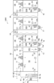
- FIG. 1 is an explanatory diagram showing the floor plan of each room of a clean room facility 100 according to the first embodiment.
- the clean room facility 100 is a facility that adjusts the temperature, room pressure, cleanliness, etc. of multiple clean rooms such as the pretreatment room R2 and the preparation room R3. etc.).
- the clean room facility 100 shown in FIG. 1 includes a changing room R1, a pretreatment room R2, a preparation room R3, a changing room R4, a undressing room R5, and three rooms R6, R7, and R8 as clean rooms. It is provided.
- a plurality of clean rooms with different air cleanliness levels are often provided.
- a difference is created between the room pressures of adjacent clean rooms.
- the preparation room R3 shown in FIG. 1 has higher air purity than the dressing room R4, and also has a higher room pressure. Therefore, when a worker opens the door D7 when entering the preparation room R3 from the dressing room R4, air flows from the preparation room R3 on the high pressure side to the dressing room R4 on the low pressure side, as shown by the dashed arrow in FIG. However, reverse flow rarely occurs. This prevents aerosols and dust from entering the preparation chamber R3 from the dressing room R4, and keeps the preparation chamber R3 clean. Note that the cleanliness of the dressing room R4 and the cleanliness of the adjustment room R3 may be made equal.
- the changing room R1 shown in FIG. 1 is a room where workers change clothes before and after work in the pretreatment room R2. Workers can come and go between the changing room R1 and the pretreatment room R2 via a door D1.
- the pretreatment room R2 is a clean room where workers perform sample pretreatment.
- a safety cabinet 31 for handling samples is provided in the pretreatment chamber R2.
- the pass box PB1 shown in FIG. 1 is a box with double doors that is used when moving a sample between the pretreatment chamber R2 and the preparation chamber R3. By moving the sample using such a pass box PB1, sample contamination can be suppressed.
- a door through which a person can enter and exit is not particularly provided between the pretreatment chamber R2 and the preparation chamber R3, but such a door may be provided as appropriate.
- Preparation room R3 is a clean room where samples are prepared.
- sample preparation means performing predetermined operations and processing on the sample. Examples of such a “sample” include, but are not limited to, cells and sterile preparations.
- the cleanliness of the preparation chamber R3 is higher than that of the pretreatment chamber R2. Further, the chamber pressure in the preparation chamber R3 is higher than the chamber pressure in the pretreatment chamber R2.
- the preparation room R3 may be provided with an equipment loading door 71 that is opened and closed when carrying in predetermined equipment.
- a safety cabinet 32 (first equipment) used for sample preparation is arranged in the preparation room R3.
- the safety cabinet 32 is a box-shaped device configured to allow an operator to process samples in a clean environment where contamination with foreign substances, microorganisms, etc. is suppressed.
- the safety cabinet 32 includes a casing (not shown) whose front and side surfaces are made of transparent glass or resin, for example, so that the work area inside the casing can be viewed from the outside.
- the safety cabinet 32 is an open type device in which the work area inside the housing communicates with the outside space through the opening described above.
- the sample processed in the safety cabinet 32 is carried out via the pass box PB2.
- an isolator (first device: not shown) may be used for sample preparation.
- the isolator includes a housing (not shown) whose front and side surfaces are made of transparent glass or resin, and the work area inside the housing is visible from the outside.
- the structure is such that the worker can handle the sample with his or her hand in a glove (not shown) installed in the front of the housing.
- Such an isolator is a so-called closed system device, and the work area is in a sealed state.
- the pressure inside the isolator housing may be positive or negative relative to the room pressure of the preparation chamber R3.
- a dressing room R4 and a dressing room R5 are provided adjacent to the preparation room R3.
- the changing room R4 is a room where workers change into predetermined clean room wear.
- the worker who has changed into clean room wear in the changing room R4, opens the door D7 and enters the preparation room R3.
- the changing room R5 is a room where workers take off their clean room wear and change into predetermined clothes. After finishing work in the preparation room R3, the worker opens the door D9 and enters the dressing room R5.
- the duct shaft DS1 shown in FIG. 1 is a wind pipe that guides a portion of the air flowing out from the preparation chamber R3 to the chamber C3 (see FIG. 2) in the attic.
- duct shafts are also appropriately provided in other clean rooms such as the pretreatment chamber R2.
- three rooms R6, R7, and R8 are provided so as to be successively adjacent to each other. These rooms R6, R7, and R8 are spaces in which equipment (second equipment) related to sample culture or testing is placed, respectively.
- an incubator 41 (second device) for culturing a sample is provided in room R6.
- another room R7 is provided with an incubator 42 (second device), and the remaining room R8 is provided with an incubator 43 (second device).
- the incubator 41 provided in the room R6 is a device for culturing the sample, as described above.
- the incubator 41 has a box shape, and the inside thereof is adjusted to a temperature and humidity suitable for culturing a sample.
- Such an incubator 41 includes a housing (not shown) and a door (not shown) installed in the housing.
- the aforementioned housing is provided with a plurality of shelves (not shown) on which containers containing samples are placed.
- the carbon dioxide concentration and the like may be adjusted as appropriate.
- the other incubators 42 and 43 have similar configurations.
- the room R6 includes a partition 6a, a door 6b, and a pair of side walls 6c and 6d.
- the partition 6a is a plate (or wall) that partitions the preparation room R3 and the room R6, and extends from the floor to the ceiling of the room R6.
- the door 6b is an openable/closable door used for moving the sample, and is provided in the partition 6a.
- the pair of side walls 6c and 6d form the right and left sides of the room R6 when viewed from a person directly facing the door 6b.
- One side wall 6c faces the wall of the preparation chamber R3.
- the other side wall 6d is a "wall" that partitions adjacent rooms R6, R7 out of the plurality of rooms R6, R7, R8.
- the pair of side walls 6c and 6d both extend from the floor to the ceiling of the room R6.
- the wall opposite to the partition 6a where the door 6b is provided is formed substantially integrally with the wall of the preparation room R3.
- the room R6 When the door 6b shown in FIG. 1 is closed, the room R6 is separated from the preparation room R3 and the other rooms R7 and R8. Thereby, even if sample contamination occurs during work in room R6, it is possible to suppress sample contamination from reaching preparation room R3 and other rooms R7 and R8. Further, when sterilizing room R6, there is no particular need to sterilize preparation room R3 and other rooms R7 and R8, so the effort and cost required for sterilization can be reduced.
- a duct shaft DS6 is provided in the room R6.
- the duct shaft DS6 is a wind conduit that guides the air flowing out from the room R6 to the chamber C3 (see FIG. 2) in the attic of the preparation room R3.
- the other rooms R7 and R8 also have the same configuration as the above-described room R6.
- the partition 6a of the room R6, the partition 7a of the room R7, and the partition 8a of the room R8 may be integrally formed.
- the cleanliness of the preparation chamber R3 and the cleanliness of each of the rooms R6, R7, and R8 may be made equal. Note that the greater the number of ventilations per unit time in the preparation room R3, etc., the higher the cleanliness.
- the chamber pressure of the preparation chamber R3 and the chamber pressure of each of the plurality of chambers R6, R7, and R8 may be different. In particular, it is preferable that the pressure in the preparation chamber R3 be higher than the pressure in each of the plurality of chambers R6, R7, and R8. As a result, even if sample contamination occurs in the room R6, for example, it is possible to suppress dust and aerosol from leaking from the room R6 to the preparation room R3 through the small gap in the door 6b.
- the cleanliness levels and set pressures of the rooms R6, R7, and R8 may be the same or different.
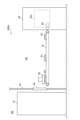
- FIG. 2 is a schematic cross-sectional view of the clean room facility 100.
- the preparation chamber R3 and three chambers R6, R7, and R8 are shown, and illustration of the pretreatment chamber R2 (see FIG. 1) and the like is appropriately omitted.
- the flow of air is shown by solid line arrows.
- FIG. 2 is a schematic cross-sectional view focusing on the flow of air, for example, air being guided from the preparation chamber R3 to the chamber C3 via the duct shaft DS1.
- illustration of the safety cabinet 32 (see FIG. 1) and the incubators 41 to 43 (see FIG. 1) is omitted.
- the clean room facility 100 includes an air conditioner 9, fan filter units 11-19, and pressure sensors 21-24.
- the air conditioner 9 is a device that adjusts the temperature of air, etc., and includes a filter 9a, a cooling coil 9b, and a fan 9c. Note that the air conditioner 9 may include an inverter 9d.
- the filter 9a collects dust from the air flowing from the preparation chamber R3 through a predetermined gap 61 toward the cooling coil 9b.
- the cooling coil 9b is a heat exchanger that exchanges heat between the air that has passed through the filter 9a and the refrigerant that flows through heat transfer tubes (not shown).
- the fan 9c is a blower that forcefully sends air whose temperature etc. have been adjusted by the cooling coil 9b to the chamber C3 via the duct K1.
- the inverter 9d is a power converter that drives a motor (not shown) of the fan 9c.
- the chamber C3 shown in FIG. 2 is a space under the ceiling of the preparation room R3.
- the chamber C3 includes a ceiling 51 of the preparation chamber R3, an upper plate 52 having a higher height than the ceiling 51, and also includes a side plate 53 and a partition wall 54.
- the side plate 53 is installed at one edge of the ceiling 51 and the upper plate 52 in the lateral direction.
- the partition wall 54 is a wall that partitions the preparation chamber R3 from the respective rooms R6, R7, and R8, and is installed at the edge of the ceiling 51 and the upper plate 52 on the other side in the lateral direction. Note that the space behind the ceiling of the preparation chamber R3 and the space behind the ceiling of the pretreatment chamber R2 (see FIG. 1) may be formed as one chamber.
- the fan filter units 11 and 12 shown in FIG. 2 are devices that supply air from the chamber C3 to the preparation chamber R3, and are embedded in the ceiling 51 of the preparation chamber R3.
- the fan filter unit 11 includes an air supply fan 11a and a filter 11b.
- the air supply fan 11a is a blower that supplies air from the chamber C3 to the preparation chamber R3.
- the filter 11b collects dust from the air flowing from the air supply fan 11a toward the preparation chamber R3, and is provided on the blowing side of the air supply fan 11a.
- a filter 11b for example, HEPA (High Efficiency Particulate Air Filter) or ULPA (Ultra Low Penetration Air Filter) is used.
- HEPA High Efficiency Particulate Air Filter
- ULPA Ultra Low Penetration Air Filter
- the fan filter unit 13 shown in FIG. 2 is a device that exhausts and returns air from the preparation chamber R3, and includes a return air fan 13a and a filter 13b.
- return air from the preparation chamber R3 means that at least a portion of the air flowing out from the preparation chamber R3 is returned to the preparation chamber R3 via the duct shaft DS1 or the like.
- air is guided from the preparation chamber R3 to the duct shaft DS1 through a predetermined gap 73 as the return air fan 13a is driven.
- a part of the air guided to the duct shaft DS1 is returned to the chamber C3 via the duct shaft DS1, and the remaining air is exhausted.
- a perforated plate 74 (or grating) is provided at the downstream end of the duct shaft DS1.
- the pressure sensor 21 shown in FIG. 2 is a sensor that detects the chamber pressure in the preparation chamber R3, and is provided in the preparation chamber R3. Then, the supply air fans 11a and 12a and the return air fan 13a are controlled so that the pressure in the preparation chamber R3 is set to a predetermined set pressure (target pressure).
- the clean room facility 100 includes a room chamber C6, fan filter units 14 and 15, a pressure sensor 22, a duct shaft DS6, a first damper 56a, and a first damper 56a as a configuration corresponding to the room R6 (see also FIG. 1). 2 damper 56b.
- the room chamber C6 is a space under the ceiling of the room R6.
- the room chamber C6 is partitioned from the adjacent room chamber C7 by a wall member (not shown), and is partitioned from the chamber C3 in the attic of the preparation room R3 by a partition wall 54.
- three room chambers C6, C7, and C8 are individually provided in the ceiling space in one-to-one correspondence with the three rooms R6, R7, and R8.
- the fan filter unit 14 shown in FIG. 2 includes an air supply fan 14a and a filter 14b, and is buried in the ceiling of the room R6.
- the air supply fan 14a is a blower that supplies air to the room R6 (the room corresponding to the room chamber C6), and is provided in the room chamber C6.
- the filter 14b collects dust from the air flowing from the room chamber C6 toward the room R6, and is provided on the blowing side of the air supply fan 14a.
- the fan filter unit 15 shown in FIG. 2 includes a return air fan 15a and a filter 15b, and is embedded in the side wall of the room R6.
- the return air fan 15a is a blower that returns air flowing out of the room R6 to the chamber C3 in the attic of the preparation room R3 via the duct shaft DS6.
- the filter 15b collects dust from the air sucked into the return air fan 15a from the room R6, and is provided on the suction side of the return air fan 15a.
- the pressure sensor 22 shown in FIG. 2 is a sensor that detects the room pressure in the room R6, and is provided in the room R6. Then, the supply air fan 14a and the return air fan 15a are controlled so that the room pressure in the room R6 is set to a predetermined set pressure (target pressure).
- the duct shaft DS6 is a wind conduit that guides the air flowing out from the room R6 to the chamber C3 in the attic of the preparation room R3.
- a perforated plate 74 (or grating) is provided at the downstream end of the duct shaft DS6.
- the first damper 56a shown in FIG. 2 communicates or blocks communication between the chamber C3 in the ceiling of the preparation room R3 and the room chamber C6. 54.
- the second damper 56b switches communication or isolation between the duct shaft DS6 and the chamber C3, and is provided near the downstream end of the duct shaft DS6, corresponding to the room R6. Note that the configurations corresponding to the remaining two rooms R7 and R8 are also similar to those corresponding to the above-mentioned room R6.
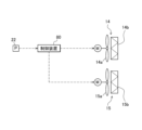
- FIG. 3 is a configuration diagram regarding control of the fan filter unit 14 on the supply air side and the fan filter unit 15 on the return air side.
- the clean room facility 100 includes a control device 80 in addition to the fan filter units 14 and 15 and the pressure sensor 22 described above, as a configuration corresponding to the room R6 (see FIG. 2).
- the control device 80 is a device that controls the supply air fan 14a and the return air fan 15a.
- the control device 80 includes electronic circuits such as a CPU (Central Processing Unit), a ROM (Read Only Memory), a RAM (Random Access Memory), and various interfaces. Then, the program stored in the ROM is read out and expanded to the RAM, and the CPU executes various processes.
- a CPU Central Processing Unit
- ROM Read Only Memory
- RAM Random Access Memory
- the input side of the control device 80 is connected to the pressure sensor 22 via wiring, and the output side is connected to the supply air fan 14a and the return air fan 15a via wiring.
- the control device 80 controls the supply air fan 14a and the return air fan 15a in a predetermined manner based on the detected value of the pressure sensor 22 so that the room pressure in the room R6 (see FIG. 2) becomes a predetermined set pressure. Note that one of the supply air fan 14a and the return air fan 15a may rotate at a constant speed.
- FIG. 3 shows the configuration related to air supply and return air in room R6 (see FIG. 2), one control device can control multiple clean rooms (preparation room R3 and rooms R6, R7, R8: FIG. 2). It may also be possible to control the supply air fan and return air fan (see ).
- FIG. 10 is an explanatory diagram showing the floor plan of each room in the clean room facility 100F according to the comparative example.
- three incubators 41 to 43 are provided in the preparation room R3, but rooms R6, R7, and R8 (see FIG. 1) that accommodate these incubators 41 to 43 are not provided.
- workers take cells in and out of the incubators 41 to 43 there is a possibility that aerosol may adhere to the equipment or floor (sample contamination), so cells from multiple patients may be placed in one preparation room R3.
- the conventional clean room facility 100F after a worker processes one patient's cells etc. in the preparation room R3, the worker sterilizes the preparation room R3 (or wipes it with alcohol) and then processes another patient's cells. I was trying to handle things like that.
- the incubators 41 to 43 are individually housed in three rooms R6, R7, and R8. Thereby, even if sample contamination occurs in room R6, for example, it is possible to suppress the sample contamination from spreading to preparation room R3 and other rooms R7 and R8. Furthermore, since the area to be sterilized (for example, room R6) is narrow, the effort and cost required for sterilization can be reduced.
- the air conditioner 9 and fan filter units 11 to 19 shown in FIG. 2 are driven in a predetermined manner.
- the first damper 56a is in an open state during normal use of the room R6 corresponding to the first damper 56a, and communicates between the chamber C3 and the room chamber C6. As a result, clean air is supplied from the chamber C3 to the room R6 via the first damper 56a and the room chamber C6 in sequence.
- the second damper 56b is in an open state during normal use of the room R6 corresponding to the second damper 56b, allowing communication between the duct shaft DS6 and the chamber C3.
- air is returned from the room R6 to the chamber C3 via the duct shaft DS6 and the second damper 56b in sequence. This air is purified in the process of passing through the fan filter units 11 and 12 on the air supply side and the filter 9a of the air conditioner 9.
- FIG. 4 is an explanatory diagram showing an example of processing during sterilization of room R8.
- a decontamination device 81 that injects a predetermined sterilizing gas (hydrogen peroxide gas, etc.) is placed in room R8.
- a predetermined sterilizing gas hydrogen peroxide gas, etc.
- the operation switch (not shown) of the decontamination device 81 is pressed with the door 8b (see FIG. 1) of the room R8 closed
- sterilization gas is injected from the decontamination device 81 and enters the room R8. Filled with sterile gas.
- the room is filled with a predetermined sterilization gas.
- the air supply fan 18a that supplies air to this room R8 is stopped, and the return air fan 19a that returns air from room R8 is also stopped.
- the room R8 is partitioned off from the preparation room R3 and the other rooms R6 and R7, and the door 6b is closed and hermetically sealed. Furthermore, since the volume and surface area of the room R8 are relatively small, sterilization can be completed in a short time.
- first damper 58a is in a closed state during sterilization of the room R8 corresponding to the first damper 58a, and blocks the chamber C3 and the room chamber C8.
- second damper 58b is in a closed state during sterilization of the room R8 corresponding to the second damper 58b, and blocks the duct shaft DS8 and the chamber C3. This can prevent sterilization gas from flowing into the preparation chamber R3 from the chamber R8 through the duct shaft DS8 and the chamber C3 in sequence during the sterilization of the chamber R8.
- the supply air fan 18a and return air fan 19a corresponding to this room R8 are stopped, and the supply air fans 14a and 16a and return air fans corresponding to other rooms R6 and R7 are stopped. 15a and 17a may be driven.
- the air conditioner 9 and the fan filter units 11 to 13 in the preparation room R3 may be driven while the room R8 is being sterilized. As a result, while the room R8 is being sterilized, the other rooms R6 and R7 and the preparation room R3 can be used, thereby increasing work efficiency when processing samples.
- FIG. 5 is an explanatory diagram showing another example of the process during sterilization of room R8.
- the decontamination device 82 shown in FIG. 5 fills a room R8 to be sterilized with a predetermined sterilizing gas (hydrogen peroxide gas, etc.), and then fills the room R8 with a predetermined catalytic gas (for example, platinum or palladium) to make the sterilizing gas harmless.
- a predetermined sterilizing gas hydrogen peroxide gas, etc.
- a predetermined catalytic gas for example, platinum or palladium
- This is a device for filling a catalyst (containing a catalyst).
- the decontamination device 82 is connected to an air supply side hose 82a and an exhaust side hose 82b.
- the air supply side hose 82a is a pipe that guides predetermined sterilization gas and catalyst gas from the decontamination device 82 to the room R8.
- the exhaust side hose 82b is a pipe that guides exhaust gas from the room R8 to the decontamin
- the decontamination device 82 When sterilizing the room R8, the decontamination device 82 supplies a predetermined sterilization gas to the room R8 via the air supply side hose 82a, and exhausts the gas from the room R8 via the exhaust side hose 82b. Further, after sterilizing room R8, the decontamination device 82 supplies a predetermined catalyst gas that renders the sterilization gas harmless to room R8 through the air supply hose 82a, and exhausts the gas from room R8 through the exhaust hose 82b. do. Note that similar processing is performed when sterilizing the other rooms R6 and R7. Further, a predetermined catalytic filter (not shown) that renders the sterilization gas harmless may be incorporated into the decontamination device 82. Further, a decomposition device (not shown) including a catalyst filter (not shown) may be separately provided.
- ⁇ Effect> According to the first embodiment, by separately providing the rooms R6, R7, and R8 in which the incubators 41 to 43 (see FIG. 1) are arranged, work can be performed in the three rooms R6, R7, and R8 in addition to the preparation room R3. It is possible to do this in parallel. This increases work efficiency when handling samples. Moreover, when a worker processes a predetermined sample in room R8 and then sterilizes this room R8, there is no particular need to sterilize the preparation room R3 or the other rooms R6 and R7. Therefore, the time and cost required for sterilization can be reduced.
- the structure of the clean room facility 100 is not particularly complicated, and the worker can efficiently process samples with a relatively simple structure. Further, since there is no particular need to provide the incubators 41 to 43 with a sterilization function, it is possible to reduce costs. Furthermore, while a worker is handling cells, etc. of a certain patient in room R6, it becomes possible for another worker to handle cells, etc. of another patient in room R7. As described above, according to the first embodiment, it is possible to provide a clean room facility 100 that is easy to use and has improved sample preparation efficiency.
- the second embodiment differs from the first embodiment in that a shutter 6e (see FIG. 6) is provided in the room R6, and shutters 7e and 8e (see FIG. 6) are provided in the rooms R7 and R8. . Furthermore, the second embodiment differs from the first embodiment in that a transport machine 90 (see FIG. 6) is used to move the sample. Note that other aspects are the same as those in the first embodiment. Therefore, the parts that are different from the first embodiment will be explained, and the explanation of the overlapping parts will be omitted.
- FIG. 6 is an explanatory diagram showing the floor plan of each room of the clean room facility 100A according to the second embodiment.
- the arrow near the transport machine 90 in FIG. 6 indicates the direction in which the sample container N1 (see FIG. 7) moves.
- Room R6 of the clean room facility 100A shown in FIG. 6 is provided with a shutter 6e that can be opened and closed.
- This shutter 6e is an openable/closable window used for moving the sample, and is provided in the partition 6a of the room R6.
- shutters 7e and 8e are also provided in other rooms R7 and R8. For example, when the sample container N1 (see FIG. 7) is transferred between the transport machine 90 and the incubator 41, the shutter 6e of the room R6 is automatically opened.
- the sizes of the shutters 6e, 7e, and 8e are preferably large enough to prevent people from entering and exiting.
- the shutters 6e, 7e, and 8e have rectangular openings, a horizontal length of 40 cm or less, and a height direction of 40 cm or less.
- the clean room facility 100A includes a transport machine 90.
- the transport machine 90 is a machine that transports the sample container N1 (see FIG. 7).
- the transport machine 90 has a function of transporting the sample container N1 (see FIG. 7) between the safety cabinet 32 (first device) and the incubators 41 to 43 (second device).
- the transport machine 90 includes a belt conveyor 91, a sorting robot 92, and a belt conveyor 93 (see FIG. 7) provided inside the safety cabinet 32.
- automatic warehouses 33a and 33b for consumable supplies and the like are provided.
- FIG. 7 is an explanatory diagram including the transport machine 90 of the clean room facility 100A.
- a sample container N1 is transported from the safety cabinet 32 to the incubator 41. Note that it is also possible to move the cultured container N1 from any of the incubators 41 to 43 to the safety cabinet 32.
- the belt conveyor 93 shown in FIG. 7 is a device that moves the sample container N1 processed in the safety cabinet 32 to the belt conveyor 91 on the downstream side.
- a belt conveyor 93 is provided in the work area 32a of the safety cabinet 32.
- Another belt conveyor 91 conveys the container N1 conveyed from the upstream belt conveyor 93 to the vicinity of the sorting robot 92.
- the sorting robot 92 grips (or suctions) the container N1 transported by the belt conveyor 91, and stores this container N1 on one of the shelves (not shown) of the incubators 41 to 43.
- an incubator for example, the incubator 41
- a shutter is provided in a housing (not shown) surrounding the movement area of the sorting robot 92, and the sorting robot 92 sorts the container N1 received through this shutter to one of the incubators 41 to 43. You can do it like this.
- ⁇ Effect> since the transport machine 90 is used to move the sample container N1, the effort and time required to move the container N1 can be reduced. Furthermore, since the number of people working in the preparation room R3 and the like can be reduced, sample contamination such as spilling samples on the floor is less likely to occur. As a result, the frequency of sterilization of the preparation room R3 and the rooms R6 to R8 is reduced, so that costs can be reduced.
- FIG. 8 is a schematic cross-sectional view of a clean room facility 100B according to a first modification.
- the clean room facility 100B shown in FIG. 8 includes, for example, a room chamber C6, fan filter units 14, 76, a duct shaft DS6, and a first damper 56a as a configuration corresponding to the room R6.
- the room chamber C6 is a space under the ceiling of the room R6.
- This room chamber C6 is partitioned from the adjacent room chamber C7 by a wall member (not shown), and from the preparation room R3 by a partition wall 54.
- a first damper 56a is provided on the partition wall 54 of the room chamber C6. Note that during normal use of the room R6, the first damper 56a is in an open state.
- the air supply fan 14a of the fan filter unit 14 is a blower that supplies air to the room R6, and is provided in the room chamber C6.
- the return air fan 76a (first return air fan) of another fan filter unit 76 has a function of returning at least a portion of the air flowing out from the room R6 to the room chamber C6 via the duct shaft DS6. There is. That is, the return air fan 76a (first return air fan) has a function of guiding a part of the air flowing out from the room R6 through a predetermined gap 79a to the duct shaft DS6 and exhausting the remaining air. .
- a perforated plate 74 (or grating) may be provided at the downstream end of the duct shaft DS6.
- the first modification shown in FIG. 8 is different from the first embodiment (see FIG. 2) in that, for example, a part of the air in the room R6 is returned to the room chamber C6 via the duct shaft DS6. It's different. According to such a configuration, since there is almost no movement of air from room R6 to preparation chamber R3, it is possible to reliably prevent aerosol from flowing into preparation chamber R3 immediately after sample contamination occurs in room R6.
- FIG. 9 is a schematic cross-sectional view of a clean room facility 100C according to a second modification.
- the second modification shown in FIG. 9 has a configuration in which fan filter units 86, 87, and 88 are added to the first modification (see FIG. 8) described above.
- the fan filter unit 86 corresponding to room R6 includes a return air fan 86a (second return air fan) and a filter 86b.
- the return air fan 86a has a function of returning at least a portion of the air flowing out from the room R6 to the room chamber C6 via the duct shaft DS6.
- the return air fan 86a (second return air fan) is a blower that guides the air flowing out from the room R6 to the duct shaft DS6 via itself (that is, the return air fan 86a). Note that the same applies to the configurations corresponding to the other rooms R7 and R8. According to such a configuration, for example, by driving the return air fans 76a and 86a together, the flow rate of air flowing from the room R6 via the duct shaft DS6 can be appropriately adjusted.
- the preparation room R3 and rooms R6, R7, and R8 are positive pressure rooms, but depending on the application, the preparation room R3 and rooms R6, R7, and R8 may be negative pressure rooms. It's okay.
- a case has been described in which the room pressure in the preparation chamber R3 and the room pressure in the rooms R6, R7, and R8 are different, but the present invention is not limited to this. That is, the pressure in the preparation chamber R3 and the pressure in the chambers R6, R7, and R8 may be made equal.
- a duct (not shown) may be separately provided to guide the air supplied through the ducts K1 and K2 (see FIG. 2) to each fan filter unit on the air supply side.
- the preparation room R3 may have a configuration in which a partition (not shown) with a window or door that is not connected to the room is provided in advance, and the above-mentioned room can be added to the preparation room R3 later. good.
- the present invention is not limited to this. That is, as “secondary equipment” related to culturing or testing samples, in addition to image capturing devices and inspection devices, subculture devices, seeding devices, cell collection devices, etc. are arranged in rooms R6, R7, and R8. Good too.
- the incubator 41 may be provided in the room R6, the image capturing device may be provided in another room R7, and the inspection device may be provided in the remaining room R8.
- different types of "second devices” installed in rooms R6, R7, and R8 may coexist.
- a plurality of "second devices” may be provided in one room (for example, room R6).
- the return air fan 15a is installed so as to return the air flowing out from the room R6 (see FIG. 2) to the chamber C3 in the ceiling of the preparation room R3 via the duct shaft DS6.
- the return air fan 15a is not limited to this.
- at least a portion of the air flowing out of the room R6 is returned to the chamber C3 in the attic of the preparation room R3 via the duct shaft DS6, and a return air fan (not shown) is used to exhaust the remaining air. ) may also be installed.
- the same thing can be said about the return air fans 17a and 19a in the other rooms R7 and R8.
- the transport machine 90 includes belt conveyors 91 and 93 and a sorting robot 92, but the present invention is not limited to this.
- the belt conveyors 91, 93 and the sorting robot 92 may be omitted, and a human being may intervene to move the container N1.
- each embodiment and the first to third modified examples can be combined as appropriate.
- the second embodiment configuration including the transport machine 90: see FIG. 7 and the first modification (see FIG. 8) may be combined.
- various combinations are possible, such as a combination of the second embodiment (see FIG. 7) and the second modification (see FIG. 9).
- each embodiment a case has been described in which the clean room facilities 100 and 100A are used for cell preparation, etc., but the present invention is not limited to this. That is, each embodiment can be applied to various other fields such as manufacturing of semiconductors, precision machinery, food industry, etc. in addition to manufacturing of pharmaceuticals.
Landscapes
- Health & Medical Sciences (AREA)
- Life Sciences & Earth Sciences (AREA)
- Engineering & Computer Science (AREA)
- Chemical & Material Sciences (AREA)
- General Health & Medical Sciences (AREA)
- Zoology (AREA)
- Bioinformatics & Cheminformatics (AREA)
- Organic Chemistry (AREA)
- Wood Science & Technology (AREA)
- General Engineering & Computer Science (AREA)
- Public Health (AREA)
- Epidemiology (AREA)
- Veterinary Medicine (AREA)
- Animal Behavior & Ethology (AREA)
- Genetics & Genomics (AREA)
- Biochemistry (AREA)
- Biomedical Technology (AREA)
- Sustainable Development (AREA)
- Biotechnology (AREA)
- Microbiology (AREA)
- Mechanical Engineering (AREA)
- Combustion & Propulsion (AREA)
- General Chemical & Material Sciences (AREA)
- Molecular Biology (AREA)
- Chemical Kinetics & Catalysis (AREA)
- Clinical Laboratory Science (AREA)
- Apparatus Associated With Microorganisms And Enzymes (AREA)
- Ventilation (AREA)
- Devices For Use In Laboratory Experiments (AREA)
Abstract
Description
<クリーンルーム施設の構成>
図1は、第1実施形態に係るクリーンルーム施設100の各部屋の間取りを示す説明図である。
なお、図1では、所定のドア(例えば、ドアD1)が開かれた場合に空気が流れる向きを白抜きの破線矢印で示している。クリーンルーム施設100は、前処理室R2や調製室R3といった複数のクリーンルームの温度や室圧、清浄度等を調整する施設であり、例えば、細胞の培養加工や無菌製剤(ワクチン、注射剤、点眼剤等)の製造に用いられる。図1に示すクリーンルーム施設100には、クリーンルームとして、更衣室R1と、前処理室R2と、調製室R3と、着衣室R4と、脱衣室R5と、3つの部屋R6,R7,R8と、が設けられている。
なお、図2では、調製室R3や3つの部屋R6,R7,R8を示し、前処理室R2(図1参照)等の図示を適宜に省略している。また、図2では、空気の流れを実線矢印で示している。図2は、例えば、調製室R3からダクトシャフトDS1を介して、チャンバC3に空気が導かれるといったように、空気の流れに着目した模式的な断面図になっている。図2では、安全キャビネット32(図1参照)やインキュベータ41~43(図1参照)の図示を省略している。
クリーンルーム施設100(図2参照)は、部屋R6(図2参照)に対応する構成として、前記したファンフィルタユニット14,15や圧力センサ22の他に、制御装置80を備えている。制御装置80は、給気ファン14aや還気ファン15aを制御する装置である。制御装置80は、図示はしないが、CPU(Central Processing Unit)、ROM(Read Only Memory)、RAM(Random Access Memory)、各種インタフェース等の電子回路を含んで構成されている。そして、ROMに記憶されたプログラムを読み出してRAMに展開し、CPUが各種処理を実行するようになっている。
図10は、比較例に係るクリーンルーム施設100Fの各部屋の間取りを示す説明図である。
図10の比較例では、調製室R3に3台のインキュベータ41~43が設けられているが、これらのインキュベータ41~43を収容する部屋R6,R7,R8(図1参照)が設けられていない。なお、インキュベータ41~43で作業員が細胞等を出し入れする過程で、機材や床面にエアロゾルが付着する(試料汚染が生じる)可能性があるため、一つの調製室R3に複数の患者の細胞等が混在している状態で処理が行われケースは少なかった。つまり、これまでのクリーンルーム施設100Fでは、作業員が調製室R3で1人の患者の細胞等を処理した後、調製室R3を滅菌(又はアルコールで清拭)した上で、別の患者の細胞等を扱うようにしていた。
クリーンルーム施設100の通常使用時には、図2に示す空調機9やファンフィルタユニット11~19が所定に駆動される。第1ダンパ56aは、この第1ダンパ56aに対応する部屋R6の通常使用時には開状態であり、チャンバC3と部屋用チャンバC6との間を連通させる。これによって、チャンバC3から第1ダンパ56a及び部屋用チャンバC6を順次に介して、清浄な空気が部屋R6に供給される。
例えば、作業員が部屋R8で作業しているときに試料をこぼすといったことがある。また、ある患者の細胞等が試料として処理された後、別の患者の細胞等が処理される際(いわゆるチェンジオーバーの際)にも滅菌が行われることが多い。
例えば、部屋R8の滅菌時には、所定の滅菌ガス(過酸化水素ガス等)を噴射する除染装置81が部屋R8に載置される。そして、部屋R8のドア8b(図1参照)が閉められた状態で、除染装置81の運転スイッチ(図示せず)が押されると、除染装置81から滅菌ガスが噴射され、部屋R8に滅菌ガスが充填される。このように、複数の部屋R6,R7,R8のうち少なくとも一つの部屋(例えば、部屋R8)の滅菌が行われる際には、当該部屋に所定の滅菌ガスが充填される。
図5に示す除染装置82は、滅菌対象の部屋R8に所定の滅菌ガス(過酸化水素ガス等)を充填した後、この滅菌ガスを無害化する所定の触媒ガス(例えば、白金やパラジウムを含む触媒)を充填する装置である。除染装置82には、給気側ホース82aが接続されるとともに、排気側ホース82bが接続される。給気側ホース82aは、除染装置82から部屋R8に所定の滅菌ガスや触媒ガスを導く管である。排気側ホース82bは、部屋R8から除染装置82に排気ガスを導く管である。
また、滅菌ガスを無害化する所定の触媒フィルタ(図示せず)を除染装置82の中に組み込むようにしてもよい。また、触媒フィルタ(図示せず)を備える分解装置(図示せず)を別途設けてもよい。
第1実施形態によれば、インキュベータ41~43(図1参照)を配置する部屋R6,R7,R8を個別に設けることで、調製室R3の他、3つの部屋R6,R7,R8で作業を並行して行うことが可能になる。これによって、試料を扱う際の作業効率が高められる。また、作業員が所定の試料を部屋R8で処理した後、この部屋R8を滅菌する際、調製室R3や他の部屋R6,R7の滅菌を行う必要が特にない。したがって、滅菌に要する時間やコストを削減できる。
第2実施形態は、部屋R6にシャッタ6e(図6参照)が設けられる他、部屋R7,R8にシャッタ7e,8e(図6参照)が設けられる点が、第1実施形態とは異なっている。また、第2実施形態は、試料の移動に搬送機械90(図6参照)が用いられる点が、第1実施形態とは異なっている。なお、その他については、第1実施形態と同様である。したがって、第1実施形態とは異なる部分について説明し、重複する部分については説明を省略する。
なお、図6の搬送機械90の付近の矢印は、試料の容器N1(図7参照)が移動する方向を示している。図6に示すクリーンルーム施設100Aの部屋R6には、開閉可能なシャッタ6eが設けられている。このシャッタ6eは、試料の移動に用いられる開閉可能な窓であり、部屋R6の仕切6aに設けられている。同様に、他の部屋R7,R8にもシャッタ7e,8eが設けられている。例えば、搬送機械90とインキュベータ41との間で試料の容器N1(図7参照)の受け渡しが行われる際には、部屋R6のシャッタ6eが自動で開くようになっている。
以下の説明では、一例として、安全キャビネット32からインキュベータ41に試料の容器N1が搬送される場合について説明する。なお、インキュベータ41~43のいずれかから安全キャビネット32に培養済みの容器N1を移動させることも可能である。
第2実施形態によれば、試料の容器N1の移動に搬送機械90が用いられることで、容器N1を移動させる際の手間や時間を削減できる。また、調製室R3等で作業を行う人の人数が少なくてすむため、試料を床にこぼすといった試料汚染が生じにくくなる。その結果、調製室R3や部屋R6~R8の滅菌の頻度が少なくなるため、低コスト化を図ることができる。
以上、本発明に係るクリーンルーム施設100,100Aについて各実施形態で説明したが、本発明はこれらの記載に限定されるものではなく、種々の変更を行うことができる。例えば、各実施形態では、部屋R6(図2参照)からダクトシャフトDS6を介して、調製室R3に空気が導かれる構成について説明したが、これに限らず、例えば、図8や図9の各変形例のようにしてもよい。
図8に示すクリーンルーム施設100Bは、例えば、部屋R6に対応する構成として、部屋用チャンバC6と、ファンフィルタユニット14,76と、ダクトシャフトDS6と、第1ダンパ56aと、を備えている。部屋用チャンバC6は、部屋R6の天井裏の空間である。この部屋用チャンバC6は、隣り合う部屋用チャンバC7との間が壁部材(図示せず)で仕切られるとともに、調製室R3との間が隔壁54で仕切られている。部屋用チャンバC6の隔壁54には、第1ダンパ56aが設けられている。なお、部屋R6の通常使用時には、第1ダンパ56aは開状態になっている。
ファンフィルタユニット14の給気ファン14aは、部屋R6への給気を行う送風機であり、部屋用チャンバC6に設けられている。別のファンフィルタユニット76の還気ファン76a(第1還気ファン)は、部屋R6から流出する空気の少なくとも一部を、ダクトシャフトDS6を介して、部屋用チャンバC6に戻す機能を有している。すなわち、還気ファン76a(第1還気ファン)は、部屋R6から所定の隙間79aを介して流出する空気の一部をダクトシャフトDS6に導き、残りの空気を排気する機能を有している。ダクトシャフトDS6の下流端には、多孔板74(又はグレーチング)が設けられていてもよい。なお、他の部屋R7,R8に対応する構成についても同様である。
要するに、図8に示す第1の変形例は、例えば、部屋R6の空気の一部がダクトシャフトDS6を介して部屋用チャンバC6に戻される点が、第1実施形態(図2参照)とは異なっている。このような構成によれば、部屋R6から調製室R3への空気の移動がほとんどないため、部屋R6で試料汚染が生じた直後に、エアロゾルが調製室R3に流入することを確実に防止できる。
図9に示す第2の変形例は、前記した第1の変形例(図8参照)にファンフィルタユニット86,87,88を追加した構成になっている。例えば、部屋R6に対応するファンフィルタユニット86は、還気ファン86a(第2還気ファン)と、フィルタ86bと、を備えている。還気ファン86aは、部屋R6から流出する空気の少なくとも一部を、ダクトシャフトDS6を介して、部屋用チャンバC6に戻す機能を有している。すなわち、還気ファン86a(第2還気ファン)は、部屋R6から流出する空気を自身(つまり、還気ファン86a)を介して、ダクトシャフトDS6に導く送風機である。なお、他の部屋R7,R8に対応する構成についても同様である。このような構成によれば、例えば、還気ファン76a,86aが共に駆動することで、部屋R6からダクトシャフトDS6を介して通流する空気の流量を適切に調整できる。
また、各実施形態では、調製室R3の室圧と、部屋R6,R7,R8の室圧と、が異なる場合について説明したが、これに限らない。すなわち、調製室R3の室圧と、部屋R6,R7,R8の室圧と、が等しくなるようにしてもよい。
また、各実施形態では、チャンバC3や部屋用チャンバC6,C7,C8にダクトが特に設けられない構成について説明したが、これに限らない。すなわち、ダクトK1,K2(図2参照)を介して供給される空気を給気側の各ファンフィルタユニットに導くダクト(図示せず)が別途設けられてもよい。
また、クリーンルーム施設100の建設時に部屋R6,R7,R8が設けられていてもよいが、これらの部屋R6,R7,R8が後付けで設置されてもよい。この場合において、調製室R3には、部屋に繋がっていない窓や扉付きの仕切(図示せず)が予め設けられ、前記した部屋を調製室R3に後から追加可能とする構成であってもよい。
また、前記した機構や構成は説明上必要と考えられるものを示しており、製品上必ずしも全ての機構や構成を示しているとは限らない。
32 安全キャビネット(第1機器)
41,42,43 インキュベータ(第2機器)
6a,7a,8a 仕切
6b,7b,8b ドア(扉)
6d,7d 側壁(壁)
6e,7e,8e シャッタ(窓)
14a,16a,18a 給気ファン
15a,17a,19a 還気ファン
54 隔壁
56a,57a,58a 第1ダンパ
56b,57b,58b 第2ダンパ
76a,77a,78a 還気ファン(第1還気ファン)
86a,87a,88a 還気ファン(第2還気ファン)
79a,79b,79c 隙間
90 搬送機械
C3 チャンバ
C6,C7,C8 部屋用チャンバ
DS6,DS7,DS8 ダクトシャフト
N1 容器
R3 調製室
R6,R7,R8 部屋
Claims (13)
- 試料の調製に用いられる第1機器が配置される調製室と、試料の培養又は検査に関わる第2機器が配置される複数の部屋と、が設けられ、
前記調製室とそれぞれの前記部屋とを仕切る仕切を備えるとともに、
前記仕切に設けられ、試料の移動に用いられる開閉可能な扉又は窓と、
複数の前記部屋のうちの隣り合っている部屋を仕切る壁と、を備えるクリーンルーム施設。 - 複数の前記部屋のうち少なくとも一つの部屋の滅菌が行われる際には、当該部屋に所定の滅菌ガスが充填されること
を特徴とする請求項1に記載のクリーンルーム施設。 - 前記調製室の清浄度と、複数の前記部屋のそれぞれの清浄度と、が等しく、
前記調製室の室圧と、複数の前記部屋のそれぞれの室圧と、が異なっていること
を特徴とする請求項1に記載のクリーンルーム施設。 - 前記調製室の室圧は、複数の前記部屋のそれぞれの室圧よりも高いこと
を特徴とする請求項3に記載のクリーンルーム施設。 - 試料の容器を搬送する搬送機械を備え、
前記搬送機械は、前記第1機器と、所定の前記部屋に設けられる前記第2機器と、の間で前記容器を搬送すること
を特徴とする請求項1に記載のクリーンルーム施設。 - 複数の前記部屋のそれぞれの天井裏に設けられる部屋用チャンバと、
前記部屋用チャンバに設けられ、当該部屋用チャンバに対応する前記部屋への給気を行う給気ファンと、
当該部屋から流出する空気の少なくとも一部を、ダクトシャフトを介して、前記調製室の天井裏のチャンバに戻す還気ファンと、を備え、
それぞれの前記部屋用チャンバは、隣り合う前記部屋用チャンバとの間が壁部材で仕切られるとともに、前記調製室との間が隔壁で仕切られていること
を特徴とする請求項1に記載のクリーンルーム施設。 - それぞれの前記部屋に対応するように、前記隔壁に設けられ、前記チャンバと前記部屋用チャンバとの間を連通又は遮断する第1ダンパと、
それぞれの前記部屋に対応するように、前記ダクトシャフトの下流端付近に設けられ、前記ダクトシャフトと前記チャンバとの間の連通又は遮断を切り替える第2ダンパと、を備えること
を特徴とする請求項6に記載のクリーンルーム施設。 - 前記第1ダンパは、当該第1ダンパに対応する前記部屋の通常使用時には、前記チャンバと前記部屋用チャンバとの間を連通させ、
前記第2ダンパは、当該第2ダンパに対応する前記部屋の通常使用時には、前記ダクトシャフトと前記チャンバとの間を連通させること
を特徴とする請求項7に記載のクリーンルーム施設。 - 前記第1ダンパは、当該第1ダンパに対応する前記部屋の滅菌中には、前記チャンバと前記部屋用チャンバとの間を遮断し、
前記第2ダンパは、当該第2ダンパに対応する前記部屋の滅菌中には、前記ダクトシャフトと前記チャンバとの間を遮断すること
を特徴とする請求項7に記載のクリーンルーム施設。 - 複数の前記部屋のうちの所定の部屋の滅菌中には、当該部屋に対応する前記給気ファン及び前記還気ファンは停止され、他の部屋に対応する前記給気ファン及び前記還気ファンは駆動されること
を特徴とする請求項6に記載のクリーンルーム施設。 - 複数の前記部屋のそれぞれの天井裏に設けられる部屋用チャンバと、
前記部屋用チャンバに設けられ、当該部屋用チャンバに対応する前記部屋への給気を行う給気ファンと、
当該部屋から流出する空気の少なくとも一部を、ダクトシャフトを介して、当該部屋に対応する前記部屋用チャンバに戻す還気ファンと、を備え、
それぞれの前記部屋用チャンバは、隣り合う前記部屋用チャンバとの間が壁部材で仕切られるとともに、前記調製室との間が隔壁で仕切られていること
を特徴とする請求項1に記載のクリーンルーム施設。 - 前記還気ファンとして、前記部屋から所定の隙間を介して流出する空気の一部を前記ダクトシャフトに導き、残りの空気を排気する第1還気ファンを備えること
を特徴とする請求項11に記載のクリーンルーム施設。 - 前記還気ファンとして、前記部屋から流出する空気を自身を介して前記ダクトシャフトに導く第2還気ファンをさらに備えること
を特徴とする請求項12に記載のクリーンルーム施設。
Priority Applications (7)
| Application Number | Priority Date | Filing Date | Title |
|---|---|---|---|
| CN202280066990.1A CN118056095A (zh) | 2022-03-09 | 2022-03-09 | 洁净室设施 |
| JP2024505713A JP7746535B2 (ja) | 2022-03-09 | 2022-03-09 | クリーンルーム施設 |
| US18/703,433 US20240410603A1 (en) | 2022-03-09 | 2022-03-09 | Clean Room Facility |
| PCT/JP2022/010208 WO2023170808A1 (ja) | 2022-03-09 | 2022-03-09 | クリーンルーム施設 |
| CA3235769A CA3235769A1 (en) | 2022-03-09 | 2022-03-09 | Clean room facility |
| EP22930792.1A EP4491958A4 (en) | 2022-03-09 | 2022-03-09 | CLEANROOM INSTALLATION |
| TW111139806A TWI911489B (zh) | 2022-03-09 | 2022-10-20 | 無塵室設施 |
Applications Claiming Priority (1)
| Application Number | Priority Date | Filing Date | Title |
|---|---|---|---|
| PCT/JP2022/010208 WO2023170808A1 (ja) | 2022-03-09 | 2022-03-09 | クリーンルーム施設 |
Publications (1)
| Publication Number | Publication Date |
|---|---|
| WO2023170808A1 true WO2023170808A1 (ja) | 2023-09-14 |
Family
ID=87936285
Family Applications (1)
| Application Number | Title | Priority Date | Filing Date |
|---|---|---|---|
| PCT/JP2022/010208 Ceased WO2023170808A1 (ja) | 2022-03-09 | 2022-03-09 | クリーンルーム施設 |
Country Status (7)
| Country | Link |
|---|---|
| US (1) | US20240410603A1 (ja) |
| EP (1) | EP4491958A4 (ja) |
| JP (1) | JP7746535B2 (ja) |
| CN (1) | CN118056095A (ja) |
| CA (1) | CA3235769A1 (ja) |
| TW (1) | TWI911489B (ja) |
| WO (1) | WO2023170808A1 (ja) |
Cited By (2)
| Publication number | Priority date | Publication date | Assignee | Title |
|---|---|---|---|---|
| WO2025062587A1 (ja) * | 2023-09-21 | 2025-03-27 | 日立グローバルライフソリューションズ株式会社 | クリーンルーム施設 |
| WO2025154283A1 (ja) * | 2024-01-19 | 2025-07-24 | 日立グローバルライフソリューションズ株式会社 | クリーンルーム施設 |
Families Citing this family (1)
| Publication number | Priority date | Publication date | Assignee | Title |
|---|---|---|---|---|
| EP4267070A4 (en) * | 2020-12-28 | 2024-12-18 | Seegene, Inc. | MOBILE DIAGNOSIS STRUCTURE |
Citations (7)
| Publication number | Priority date | Publication date | Assignee | Title |
|---|---|---|---|---|
| JP2005030628A (ja) * | 2003-07-08 | 2005-02-03 | Hitachi Plant Eng & Constr Co Ltd | クリーンルーム |
| JP2007195772A (ja) * | 2006-01-27 | 2007-08-09 | Daikin Ind Ltd | 滅菌システム |
| JP2008014523A (ja) * | 2006-07-03 | 2008-01-24 | Daikin Ind Ltd | 空調システム |
| JP2013240358A (ja) * | 2013-08-26 | 2013-12-05 | Regene Pharm:Kk | ユニット型細胞培養施設 |
| JP2014054229A (ja) * | 2012-09-13 | 2014-03-27 | Dainippon Printing Co Ltd | 細胞培養方法及び装置 |
| JP2015092849A (ja) * | 2013-11-12 | 2015-05-18 | 東京エレクトロン株式会社 | 多能性幹細胞の培養方法及び施設 |
| WO2021111550A1 (ja) * | 2019-12-04 | 2021-06-10 | 日立グローバルライフソリューションズ株式会社 | 空調システム |
Family Cites Families (7)
| Publication number | Priority date | Publication date | Assignee | Title |
|---|---|---|---|---|
| KR100524875B1 (ko) * | 2003-06-28 | 2005-10-31 | 엘지.필립스 엘시디 주식회사 | 청정시스템 |
| JP2009002634A (ja) * | 2007-06-25 | 2009-01-08 | Unitec Inc | ユニット型クリーンルーム |
| JP5592080B2 (ja) * | 2009-05-08 | 2014-09-17 | 株式会社日立製作所 | 細胞培養方法、細胞培養システム |
| JP6955450B2 (ja) * | 2018-01-17 | 2021-10-27 | 日立グローバルライフソリューションズ株式会社 | 空調制御システム及び空調制御方法 |
| JP7339528B2 (ja) * | 2019-10-25 | 2023-09-06 | ノイルイミューン・バイオテック株式会社 | 遺伝子改変細胞作製システム |
| US12455083B2 (en) * | 2019-12-16 | 2025-10-28 | Cuorips Inc. | Facility and implementation method for manufacturing of article using said facility |
| CN214740889U (zh) * | 2021-03-02 | 2021-11-16 | 广州市嘉润实业有限公司 | 一种实验室洁净杀菌隔离门 |
-
2022
- 2022-03-09 EP EP22930792.1A patent/EP4491958A4/en active Pending
- 2022-03-09 WO PCT/JP2022/010208 patent/WO2023170808A1/ja not_active Ceased
- 2022-03-09 CA CA3235769A patent/CA3235769A1/en active Pending
- 2022-03-09 US US18/703,433 patent/US20240410603A1/en active Pending
- 2022-03-09 JP JP2024505713A patent/JP7746535B2/ja active Active
- 2022-03-09 CN CN202280066990.1A patent/CN118056095A/zh active Pending
- 2022-10-20 TW TW111139806A patent/TWI911489B/zh active
Patent Citations (7)
| Publication number | Priority date | Publication date | Assignee | Title |
|---|---|---|---|---|
| JP2005030628A (ja) * | 2003-07-08 | 2005-02-03 | Hitachi Plant Eng & Constr Co Ltd | クリーンルーム |
| JP2007195772A (ja) * | 2006-01-27 | 2007-08-09 | Daikin Ind Ltd | 滅菌システム |
| JP2008014523A (ja) * | 2006-07-03 | 2008-01-24 | Daikin Ind Ltd | 空調システム |
| JP2014054229A (ja) * | 2012-09-13 | 2014-03-27 | Dainippon Printing Co Ltd | 細胞培養方法及び装置 |
| JP2013240358A (ja) * | 2013-08-26 | 2013-12-05 | Regene Pharm:Kk | ユニット型細胞培養施設 |
| JP2015092849A (ja) * | 2013-11-12 | 2015-05-18 | 東京エレクトロン株式会社 | 多能性幹細胞の培養方法及び施設 |
| WO2021111550A1 (ja) * | 2019-12-04 | 2021-06-10 | 日立グローバルライフソリューションズ株式会社 | 空調システム |
Non-Patent Citations (1)
| Title |
|---|
| See also references of EP4491958A4 * |
Cited By (4)
| Publication number | Priority date | Publication date | Assignee | Title |
|---|---|---|---|---|
| WO2025062587A1 (ja) * | 2023-09-21 | 2025-03-27 | 日立グローバルライフソリューションズ株式会社 | クリーンルーム施設 |
| WO2025154283A1 (ja) * | 2024-01-19 | 2025-07-24 | 日立グローバルライフソリューションズ株式会社 | クリーンルーム施設 |
| JPWO2025154283A1 (ja) * | 2024-01-19 | 2025-07-24 | ||
| JP7825739B2 (ja) | 2024-01-19 | 2026-03-06 | 日立グローバルライフソリューションズ株式会社 | クリーンルーム施設 |
Also Published As
| Publication number | Publication date |
|---|---|
| US20240410603A1 (en) | 2024-12-12 |
| JP7746535B2 (ja) | 2025-09-30 |
| CA3235769A1 (en) | 2023-09-14 |
| JPWO2023170808A1 (ja) | 2023-09-14 |
| TWI911489B (zh) | 2026-01-11 |
| CN118056095A (zh) | 2024-05-17 |
| EP4491958A4 (en) | 2026-01-14 |
| TW202336225A (zh) | 2023-09-16 |
| EP4491958A1 (en) | 2025-01-15 |
Similar Documents
| Publication | Publication Date | Title |
|---|---|---|
| JP7746535B2 (ja) | クリーンルーム施設 | |
| CN107073469B (zh) | 向洁净室、隔离或容纳隔间、隔舱提供辅助设备的模块化部件或模块 | |
| JP6081269B2 (ja) | アイソレータシステム | |
| CA3150088C (en) | Air conditioning system | |
| JP6338521B2 (ja) | アイソレータ | |
| JPWO2019012696A1 (ja) | 安全キャビネットおよびその滅菌方法 | |
| CN110479388B (zh) | 一种用于干细胞制备的无菌操作装置 | |
| JP7027239B2 (ja) | 滅菌ガス浄化閉鎖系装置 | |
| CN113308338A (zh) | 能够连续运行的组合式实验平台及其管理方法 | |
| JP2018114202A (ja) | 除染装置及びそれを備える空気清浄システム | |
| JP2003047457A (ja) | ベクター作製施設およびベクター作製方法 | |
| JP4632737B2 (ja) | 細胞培養施設 | |
| CN215162569U (zh) | 能够连续运行的组合式实验平台 | |
| JP2005326093A (ja) | 簡易型バイオクリーンルーム | |
| KR20220113452A (ko) | 설비 및 이를 이용한 물품의 제조방법 | |
| JP7330611B2 (ja) | 試料保管装置及び試料保管システム | |
| TWI893499B (zh) | 無塵室設施 | |
| JP7425647B2 (ja) | クリーンルーム及びクリーンルームの使用方法 | |
| CN220737602U (zh) | 具备等离子消杀功能的ⅱ级生物安全柜 | |
| CN210385941U (zh) | 一种多层结构的净化工作台 | |
| WO2025215829A1 (ja) | クリーンルーム施設 | |
| TW202530602A (zh) | 無塵室設施 | |
| CA3219696A1 (en) | Air conditioning system | |
| HK1242648A1 (en) | Modular parts that supply utilities to cleanroom, isolation or containment cubicles, pods, or modules | |
| JP2018068945A (ja) | 物品処理システム |
Legal Events
| Date | Code | Title | Description |
|---|---|---|---|
| 121 | Ep: the epo has been informed by wipo that ep was designated in this application |
Ref document number: 22930792 Country of ref document: EP Kind code of ref document: A1 |
|
| ENP | Entry into the national phase |
Ref document number: 2024505713 Country of ref document: JP Kind code of ref document: A |
|
| WWE | Wipo information: entry into national phase |
Ref document number: 202280066990.1 Country of ref document: CN |
|
| WWE | Wipo information: entry into national phase |
Ref document number: 3235769 Country of ref document: CA |
|
| WWE | Wipo information: entry into national phase |
Ref document number: 18703433 Country of ref document: US |
|
| WWE | Wipo information: entry into national phase |
Ref document number: 2022930792 Country of ref document: EP |
|
| NENP | Non-entry into the national phase |
Ref country code: DE |
|
| ENP | Entry into the national phase |
Ref document number: 2022930792 Country of ref document: EP Effective date: 20241009 |