WO2023176435A1 - 2サイクルエンジン - Google Patents
2サイクルエンジン Download PDFInfo
- Publication number
- WO2023176435A1 WO2023176435A1 PCT/JP2023/007374 JP2023007374W WO2023176435A1 WO 2023176435 A1 WO2023176435 A1 WO 2023176435A1 JP 2023007374 W JP2023007374 W JP 2023007374W WO 2023176435 A1 WO2023176435 A1 WO 2023176435A1
- Authority
- WO
- WIPO (PCT)
- Prior art keywords
- fuel
- crank
- piston
- stroke engine
- large end
- Prior art date
- Legal status (The legal status is an assumption and is not a legal conclusion. Google has not performed a legal analysis and makes no representation as to the accuracy of the status listed.)
- Ceased
Links
Images



Classifications
-
- F—MECHANICAL ENGINEERING; LIGHTING; HEATING; WEAPONS; BLASTING
- F02—COMBUSTION ENGINES; HOT-GAS OR COMBUSTION-PRODUCT ENGINE PLANTS
- F02B—INTERNAL-COMBUSTION PISTON ENGINES; COMBUSTION ENGINES IN GENERAL
- F02B33/00—Engines characterised by provision of pumps for charging or scavenging
- F02B33/02—Engines with reciprocating-piston pumps; Engines with crankcase pumps
- F02B33/04—Engines with reciprocating-piston pumps; Engines with crankcase pumps with simple crankcase pumps, i.e. with the rear face of a non-stepped working piston acting as sole pumping member in co-operation with the crankcase
-
- F—MECHANICAL ENGINEERING; LIGHTING; HEATING; WEAPONS; BLASTING
- F02—COMBUSTION ENGINES; HOT-GAS OR COMBUSTION-PRODUCT ENGINE PLANTS
- F02M—SUPPLYING COMBUSTION ENGINES IN GENERAL WITH COMBUSTIBLE MIXTURES OR CONSTITUENTS THEREOF
- F02M61/00—Fuel-injectors not provided for in groups F02M39/00 - F02M57/00 or F02M67/00
- F02M61/14—Arrangements of injectors with respect to engines; Mounting of injectors
-
- F—MECHANICAL ENGINEERING; LIGHTING; HEATING; WEAPONS; BLASTING
- F01—MACHINES OR ENGINES IN GENERAL; ENGINE PLANTS IN GENERAL; STEAM ENGINES
- F01M—LUBRICATING OF MACHINES OR ENGINES IN GENERAL; LUBRICATING INTERNAL COMBUSTION ENGINES; CRANKCASE VENTILATING
- F01M3/00—Lubrication specially adapted for engines with crankcase compression of fuel-air mixture or for other engines in which lubricant is contained in fuel, combustion air, or fuel-air mixture
-
- F—MECHANICAL ENGINEERING; LIGHTING; HEATING; WEAPONS; BLASTING
- F02—COMBUSTION ENGINES; HOT-GAS OR COMBUSTION-PRODUCT ENGINE PLANTS
- F02B—INTERNAL-COMBUSTION PISTON ENGINES; COMBUSTION ENGINES IN GENERAL
- F02B25/00—Engines characterised by using fresh charge for scavenging cylinders
- F02B25/14—Engines characterised by using fresh charge for scavenging cylinders using reverse-flow scavenging, e.g. with both outlet and inlet ports arranged near bottom of piston stroke
-
- F—MECHANICAL ENGINEERING; LIGHTING; HEATING; WEAPONS; BLASTING
- F02—COMBUSTION ENGINES; HOT-GAS OR COMBUSTION-PRODUCT ENGINE PLANTS
- F02B—INTERNAL-COMBUSTION PISTON ENGINES; COMBUSTION ENGINES IN GENERAL
- F02B75/00—Other engines
- F02B75/02—Engines characterised by their cycles, e.g. six-stroke
-
- F—MECHANICAL ENGINEERING; LIGHTING; HEATING; WEAPONS; BLASTING
- F02—COMBUSTION ENGINES; HOT-GAS OR COMBUSTION-PRODUCT ENGINE PLANTS
- F02F—CYLINDERS, PISTONS OR CASINGS, FOR COMBUSTION ENGINES; ARRANGEMENTS OF SEALINGS IN COMBUSTION ENGINES
- F02F7/00—Casings, e.g. crankcases
-
- F—MECHANICAL ENGINEERING; LIGHTING; HEATING; WEAPONS; BLASTING
- F02—COMBUSTION ENGINES; HOT-GAS OR COMBUSTION-PRODUCT ENGINE PLANTS
- F02M—SUPPLYING COMBUSTION ENGINES IN GENERAL WITH COMBUSTIBLE MIXTURES OR CONSTITUENTS THEREOF
- F02M69/00—Low-pressure fuel-injection apparatus ; Apparatus with both continuous and intermittent injection; Apparatus injecting different types of fuel
- F02M69/10—Low-pressure fuel-injection apparatus ; Apparatus with both continuous and intermittent injection; Apparatus injecting different types of fuel peculiar to scavenged two-stroke engines, e.g. injecting into crankcase-pump chamber
-
- F—MECHANICAL ENGINEERING; LIGHTING; HEATING; WEAPONS; BLASTING
- F02—COMBUSTION ENGINES; HOT-GAS OR COMBUSTION-PRODUCT ENGINE PLANTS
- F02B—INTERNAL-COMBUSTION PISTON ENGINES; COMBUSTION ENGINES IN GENERAL
- F02B75/00—Other engines
- F02B75/02—Engines characterised by their cycles, e.g. six-stroke
- F02B2075/022—Engines characterised by their cycles, e.g. six-stroke having less than six strokes per cycle
- F02B2075/025—Engines characterised by their cycles, e.g. six-stroke having less than six strokes per cycle two
-
- F—MECHANICAL ENGINEERING; LIGHTING; HEATING; WEAPONS; BLASTING
- F02—COMBUSTION ENGINES; HOT-GAS OR COMBUSTION-PRODUCT ENGINE PLANTS
- F02B—INTERNAL-COMBUSTION PISTON ENGINES; COMBUSTION ENGINES IN GENERAL
- F02B2710/00—Gas engines
- F02B2710/03—Two stroke engines
- F02B2710/036—Scavenging or charging channels or openings
-
- Y—GENERAL TAGGING OF NEW TECHNOLOGICAL DEVELOPMENTS; GENERAL TAGGING OF CROSS-SECTIONAL TECHNOLOGIES SPANNING OVER SEVERAL SECTIONS OF THE IPC; TECHNICAL SUBJECTS COVERED BY FORMER USPC CROSS-REFERENCE ART COLLECTIONS [XRACs] AND DIGESTS
- Y02—TECHNOLOGIES OR APPLICATIONS FOR MITIGATION OR ADAPTATION AGAINST CLIMATE CHANGE
- Y02T—CLIMATE CHANGE MITIGATION TECHNOLOGIES RELATED TO TRANSPORTATION
- Y02T10/00—Road transport of goods or passengers
- Y02T10/10—Internal combustion engine [ICE] based vehicles
- Y02T10/12—Improving ICE efficiencies
Definitions
- the present disclosure relates to a piston-valve two-stroke engine.
- a fuel injection type two-stroke engine in which a main scavenging passage and an auxiliary scavenging passage are formed in a cylinder block.
- a fuel injection device is attached to the crankcase.
- the fuel injector is oriented to inject fuel toward the scavenging inlet of the auxiliary scavenging passage.
- Other known fuel injection methods include a method in which fuel is injected into an intake path leading to the crank chamber, and a method in which fuel is directly injected into a combustion chamber.
- the present inventors have discovered that in a piston-valve type two-stroke engine, lubrication and cooling at the large end of the connecting rod located in the crankcase are important. Fuel such as gasoline is mixed with oil and supplied (injected) as a mixed fuel. From the viewpoint of low fuel consumption and environmental considerations, a two-stroke engine that can perform lubrication and cooling with a small amount of mixed fuel is desired.
- This disclosure describes a two-stroke engine that can provide big end lubrication and cooling with a small amount of mixed fuel.
- One aspect of the present disclosure is a piston-valve two-stroke engine (1) in which an intake port is opened and closed by a piston (4) that reciprocates along the axial direction within a bore (3) of a cylinder (2).
- a crankcase connected to a cylinder (2) and having a crank chamber (6a), a crank mechanism (7) arranged in the crank chamber (6a) and rotating around a crankshaft (7a), and a piston (4).
- a connecting rod having a connected small end (21) and a large end (22) connected to the crank mechanism (7); It includes a fuel injector (30) that injects mixed fuel in the tangential direction of the orbit and sprays the mixed fuel onto the large end (22).
- the fuel injector (30) attached to the crankcase sprays the mixed fuel onto the large end (22) of the connecting rod.
- the fuel injector (30) injects the mixed fuel in the tangential direction of the circumferential trajectory of the large end (22).
- the oil contained in the mixed fuel lubricates and cools the big end (22).
- the large end (22) is also cooled by the fuel (eg, gasoline) contained in the mixed fuel. Thereby, the large end (22) can be lubricated and cooled with a small amount of mixed fuel.
- the mixed fuel is injected into the crankcase rather than into the combustion chamber or the bore portion (3), there is no need to consider pressure resistance and heat resistance with respect to the peripheral configuration of the fuel injector (30).
- the injection port (31) of the fuel injector (30) may protrude into the crank chamber (6a). According to this configuration, the mixed fuel can be injected from a position closer to the large end (22), making it easier to obtain the desired lubrication and cooling effects described above.
- the crank mechanism (7) has a pair of crank webs (7b) connected to the crankshaft (7a) and spaced apart in the axial direction of the crankshaft (7a), and includes an injection port (31) of the fuel injector (30). may be disposed at a position passing through the gap (G) between the pair of crank webs (7b). According to this configuration, the injection port (31) can be brought closer to the large end (22), and the large end (22) can be cooled more reliably and effectively.
- the fuel injector (30) may be configured to inject the mixed fuel into the big end (22) at least when the piston (4) is located at top dead center. According to this configuration, since the fuel injection is timed with the scavenging timing, it is easy to introduce the fuel sprayed onto the large end (22) into the scavenging hole.
- a scavenging hole (14) is formed in the cylinder (2), and the inlet (14a) of the scavenging hole (14) that opens toward the crank chamber (6a) is connected to the injection hole of the fuel injector (30) in the axial direction. It may be located at the same height as the mouth (31). According to this configuration, the fuel sprayed onto the large end (22) is easily introduced into the scavenging hole (14). Since the mixed fuel remains near the entrance (14a) of the scavenging hole (14), the fuel is easily introduced into the scavenging hole (14). This makes it possible to reduce wasted fuel that is not introduced into the scavenging hole (14), and also provides the effect of reducing fuel consumption. Furthermore, transient response and startability are improved.
- lubrication and cooling at the big end can be performed with a small amount of mixed fuel.
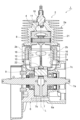
- FIG. 1 is a longitudinal sectional view of a two-stroke engine according to an embodiment of the present disclosure.
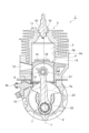
- FIG. 2 is a sectional view taken along line II-II in FIG.
- FIG. 3 is a longitudinal sectional view showing a state in which the piston is located at the bottom dead center.
- FIG. 4 is a cross-sectional view taken along line IV-IV in FIG.
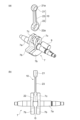
- FIG. 5(a) is an exploded perspective view showing the crank mechanism and the connecting rod
- FIG. 5(b) is a side view showing the crank mechanism and the connecting rod.
- FIG. 6 is a block diagram showing a schematic configuration related to injection control of mixed fuel in a fuel injector.
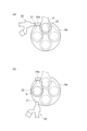
- FIG. 7(a) is a diagram showing the injection timing of the mixed fuel in the two-stroke engine of FIG. 1
- FIG. 7(b) is a diagram showing the injection timing of the mixed fuel in the two-stroke engine according to a modification.
- an engine (2-cycle engine) 1 is a 2-stroke engine that employs a cinere system as a scavenging method, and is installed, for example, in brush cutters, backpack power spreaders, etc. .
- the engine 1 includes a cylinder 2, a piston 4 that reciprocates within a bore 3 within the cylinder 2, a crankcase 6 connected below the cylinder 2 and having a crank chamber 6a, and a crankcase 6 having a crank chamber 6a.
- a crank mechanism 7 is provided.
- a piston pin 8 provided within the piston 4 and a crank pin 9 of a crank mechanism 7 provided within the crankcase 6 are connected by a connecting rod 10.
- the piston 4 is disposed within the bore portion 3 and is capable of reciprocating along the axis L direction between the combustion chamber 11 and the crank chamber 6a.
- the connecting rod 10 will be referred to as a connecting rod 10.
- the cylinder 2 includes a combustion chamber 11, a cylindrical bore part 3 that is connected to the combustion chamber 11 and into which the piston 4 is inserted, an intake port 12 and an exhaust port 13 that communicate with the bore part 3, and a pair of intake sides.
- a scavenging hole 14 and a pair of exhaust side scavenging holes 16 are formed.
- the cylinder 2 has a cylinder body 2a and a pair of scavenging cassettes 2b fitted into the lower part of the cylinder body 2a.
- the pair of scavenging cassettes 2b are fitted into two openings formed to face each other in the radial direction of the bore portion 3 and are fixed.
- the pair of intake side scavenging holes 14 and the pair of exhaust side scavenging holes 16 are formed by, for example, the cylinder body 2a and the pair of scavenging cassettes 2b (see FIG. 2).
- the bore portion 3 has a cylindrical bore surface 3a and extends inside the cylinder 2 along the axis L direction.
- the bore portion 3 is open at its bottom dead center side (lower side in the figure) and communicates with the crank chamber 6a.
- a recessed combustion chamber 11 is formed at the end of the bore portion 3 on the top dead center side, and a discharge electrode such as a spark plug 18 is disposed inside the combustion chamber 11.
- a spark plug mounting hole 19 into which a spark plug 18 is mounted is provided near the combustion chamber 11 of the cylinder body 2a.
- the intake port 12 and the exhaust port 13 are each communicated with the bore portion 3, and the exhaust port 13 is arranged slightly closer to the top dead center than the intake port 12 in the direction of the axis L.
- the intake port 12 and the exhaust port 13 are arranged to be offset from each other by approximately 180° in the circumferential direction of the bore portion 3 so as to face each other in the radial direction of the bore portion 3 .
- the intake side scavenging hole 14 is for introducing fresh gas containing fuel into the bore portion 3 and the combustion chamber 11 during the scavenging process, and extends inside the side wall of the cylinder 2 along the axis L direction. ing.
- Fresh air gas is a fuel mixture for engine operation, which is a mixture of air and a fuel mixture consisting of gasoline and oil.
- the ends of the intake side scavenging holes 14 on the top dead center side communicate with the bore portions 3 at substantially the same positions as the exhaust ports 13 in the axis L direction.
- the intake side scavenging holes 14 are spaced apart from each other in the circumferential direction of the bore portion 3 .
- the intake side scavenging holes 14 are arranged approximately symmetrically with respect to a virtual line connecting the intake port 12 and the exhaust port 13 in the radial direction.
- the intake side scavenging hole 14 is provided so that fresh gas introduced into the bore portion 3 is directed toward the intake port 12.
- An end of the intake side scavenging hole 14 on the bottom dead center side communicates with the crank chamber 6a.
- An end (not shown) on the bottom dead center side of the exhaust side scavenging hole 16 communicates with the above-mentioned crank chamber 6a.
- the exhaust side scavenging hole 16 is for introducing EGR (Exhaust Gas Recirculation) gas, which is exhaust gas after combustion with a lower fuel content than the working gas, into the bore part 3 and the combustion chamber 11 during the scavenging process. It extends inside the side wall of the cylinder 2 along the axis L direction. The ends of the exhaust scavenging holes 16 on the top dead center side communicate with the bore portion 3 at substantially the same positions as the exhaust ports 13 in the direction of the axis L. The exhaust scavenging holes 16 are spaced apart from each other in the circumferential direction of the bore portion 3 .
- EGR exhaust Gas Recirculation
- the exhaust side scavenging holes 16 are arranged approximately symmetrically with respect to a virtual line connecting the intake port 12 and the exhaust port 13 in the radial direction.
- the exhaust side scavenging hole 16 is provided so that the EGR gas introduced into the bore portion 3 is directed toward the intake port 12.
- the exhaust port 13 and the exhaust side scavenging hole 16 are connected, and the exhaust gas after combustion is passed from the exhaust port 13 as EGR gas to the exhaust side scavenging hole. 16 may be provided.
- the engine 1 is a piston-valve type two-stroke engine in which the intake port 12 is opened and closed by the piston 4 that reciprocates within the bore portion 3.
- air is introduced from the intake port 12, while a mixed fuel containing gasoline and oil is introduced into the crank chamber 6a for cooling the large end 22 of the connecting rod 10. Injected inside.
- air and the mixed fuel are mixed in the crank chamber 6a of the crankcase 6, and the fuel mixture is generated.
- the crank mechanism 7 includes a crankshaft 7a, a pair of crank webs 7b connected to the crankshaft 7a, and a pair of crank webs 7b provided on opposite sides of the crank webs 7b in the radial direction. It has a connecting part 7c.
- the connecting rod 10 has a small end 21 rotatably connected to the piston 4 via the piston pin 8 by inserting the piston pin 8 into the pin insertion hole 21a, and a crank pin 9 into the pin insertion hole 22a. It has a large end 22 that is inserted through and rotatably connected to the connecting part 7c of the crank mechanism 7 via the crank pin 9, and a rod body 23 that connects the small end 21 and the large end 22. .
- crank web 7b, the connecting portion 7c, and the crankshaft 7a are integrally molded.
- the crank pin 9 inserted through the pair of connecting portions 7c is joined and fixed to these connecting portions 7c, and the crank mechanism 7 as a whole forms a rigid body.
- the pair of crank webs 7b have a fan shape centered around the crankshaft 7a, and rotate around the crankshaft 7a while being guided by the cylindrical wall surface of the crank chamber 6a.
- the pair of crank webs 7b extend parallel to each other and are spaced apart in the axial direction of the crankshaft 7a.
- a gap G is formed between the pair of crank webs 7b.
- the engine 1 includes a fuel injection nozzle (fuel injector) 30 that sprays mixed fuel toward the large end 22 of the connecting rod 10.
- the fuel injection nozzle 30 is attached to the upper part of the crankcase 6 near the position where it is connected to the cylinder body 2a.
- a tip portion of a fuel injection nozzle 30 including an injection port 31 through which mixed fuel is injected is fitted into the crankcase 6 from the outside to the inside.
- the injection port 31 of the fuel injection nozzle 30 is oriented, for example, in a direction that intersects both the axis L direction of the bore portion 3 and the axial direction of the crankshaft 7a. More specifically, the injection port 31 of the fuel injection nozzle 30 is oriented in a direction perpendicular to both the axis L direction of the bore portion 3 and the axial direction of the crankshaft 7a.
- FIG. 4 is a cross-sectional view taken along line IV-IV in FIG. 1.
- the fuel injection nozzle 30 is arranged in the diametrical direction of the bore portion 3 (bore surface 3a) in plan view.
- the injection port 31 of the fuel injection nozzle 30 slightly protrudes into the crank chamber 6a.
- the injection port 31 is arranged at a position that passes through a gap G between the pair of crank webs 7b (see FIG. 5(b)) while the crank mechanism 7 is rotating. Due to this structure in which the injection port 31 faces (faces) the gap G, there is a positional relationship in which no other member exists between the injection port 31 and the pin insertion hole 22a.
- the inlets 14a of the pair of intake side scavenging holes 14 are located near the side of the injection port 31.
- the pair of inlets 14a are open toward the crank chamber 6a.
- the pair of inlets 14a also communicate with a pair of exhaust side scavenging holes 16.
- the distance between the injection port 31 and the inlet 14a along the circumferential direction is shorter than one quarter of the length of the circumferential surface of the bore surface 3a (inner circumferential surface of the bore portion 3). That is, the injection port 31 and one of the intake side scavenging holes 14 are arranged within a range of 90° in terms of central angle with respect to the axis L of the bore portion 3 as a reference.
- the injection port 31 and the other intake-side scavenging hole 14 are arranged within a range of 90° in terms of central angle with respect to the axis L of the bore portion 3 .
- the inlet 14a of the intake side scavenging hole 14 is located at the same height as the injection port 31 of the fuel injection nozzle 30 in the direction of the axis L. In other words, the injection port 31 of the fuel injection nozzle 30 is located at the height of the upper end of the crankcase 6.
- the fuel injection nozzle 30 injects the mixed fuel in the tangential direction of the circumferential trajectory of the large end 22.
- the period during which the mixed fuel is injected from the fuel injection nozzle 30 includes at least the time when the piston 4 is located at the top dead center (at that time, the pin large end 22 is also located at the uppermost position). Injection of the mixed fuel from the fuel injection nozzle 30 may be continued until, for example, 30 degrees after top dead center. In other words, the period during which the mixed fuel is injected from the fuel injection nozzle 30 is when the piston 4 is located at the top dead center (at 0°) or slightly before it (about several degrees to 15 degrees). It may start at 30° after top dead center.
- the fuel injection nozzle 30 is configured to spray mixed fuel onto the large end 22 of the connecting rod 10 . The fuel injection nozzle 30 injects the mixed fuel while the large end 22 passes in front of the injection port 31 .
- the injection timing of the mixed fuel in the fuel injection nozzle 30 is controlled by the ECU 40 that controls the engine 1, as shown in FIG.
- the ECU 40 controls the valve 50 and the fuel injection nozzle 30 to open and close the intake path to the intake port 12 based on the throttle opening information input from the throttle sensor S1 and the rotation angle information of the crank mechanism 7 input from the angle sensor S2. control.
- the above-described injection timing (injection period) can be adjusted as appropriate by the ECU 40 based on the state of the engine 1.
- the fuel injection nozzle 30 is an electronically controlled injector, and can adjust the injection amount of the mixed fuel with high precision.
- the ECU 40 causes the fuel injection nozzle 30 to inject a mixed fuel corresponding to a controllable limit value (minimum amount).
- the fuel injection nozzle 30 is configured to spray the mixed fuel onto the large end portion 22 at least when the piston 4 is located at the top dead center.
- the mixed fuel line (path) connected to the fuel injection nozzle 30 is omitted.
- the mixed fuel injected from the injection port 31 may be radial or linear.
- the type of nozzle may be selected as appropriate.
- the injection direction (center axis direction of injection) of the fuel injection nozzle 30 intersects the axis L and crosses the bore portion 3 in plan view.
- the central axis direction of the injection of the fuel injection nozzle 30 is perpendicular to the axis L, for example.
- the central axis direction of the injection of the fuel injection nozzle 30 is also perpendicular to the axial direction of the crankshaft 7a.
- the crank chamber 6a when the piston 4 is located near the top dead center, the mixed fuel is injected from the fuel injection nozzle 30 under the control of the ECU 40. The mixed fuel is sprayed onto the large end 22 of the connecting rod 10, thereby lubricating and cooling the large end 22. The injection of the mixed fuel is stopped immediately after the piston 4 starts descending (at the latest by 30° after the above-mentioned top dead center). Air and mixed fuel are mixed in the crank chamber 6a to generate fresh air gas.
- the exhaust port 13 is opened and the combustion gas is exhausted (see FIG. 3). Then, a little later than the opening of the exhaust port 13, the intake side scavenging hole 14 and the exhaust side scavenging hole 16 are exposed in the bore portion 3, and the scavenging stroke is started.
- the injection of the mixed fuel is close to the timing of the start of the scavenging process. Further, the distance from the injection port 31 to the inlet 14a of the intake side scavenging hole 14 is also short.
- the mixed fuel fresh air gas
- the exhaust side scavenging holes 16 are filled with EGR gas
- the intake side scavenging holes 14 are filled with fresh air gas.
- the fuel injection nozzle 30 attached to the crankcase 6 sprays the mixed fuel onto the large end 22 of the connecting rod 10. At this time, the fuel injection nozzle 30 injects the mixed fuel in the tangential direction of the circumferential trajectory of the large end portion 22 .
- the oil contained in the mixed fuel lubricates and cools the big end 22.
- the large end portion 22 is also cooled by the gasoline contained in the mixed fuel. Thereby, the large end portion 22 can be lubricated and cooled with a small amount of mixed fuel. Further, since the mixed fuel is injected into the crankcase 6 rather than into the combustion chamber 11 or the bore portion 3, there is no need to consider pressure resistance and heat resistance regarding the peripheral configuration of the fuel injection nozzle 30.
- the injection port 31 of the fuel injection nozzle 30 projects into the crank chamber 6a. This allows the mixed fuel to be injected from a position closer to the large end 22, making it easier to obtain the desired lubrication and cooling effects described above.
- the injection port 31 of the fuel injection nozzle 30 is arranged at a position passing through the gap G between the pair of crank webs 7b. Thereby, the injection port 31 can be brought closer to the large end 22, and the large end can be cooled more reliably and effectively.
- the fuel injection nozzle 30 is configured to inject the mixed fuel into the large end portion 22 at least when the piston 4 is located at the top dead center. As a result, the fuel injection is synchronized with the scavenging timing, so that the fuel sprayed onto the large end portion 22 can be easily introduced into the intake side scavenging hole 14.
- the inlet 14a of the intake side scavenging hole 14 is located at the same height as the injection port 31 of the fuel injection nozzle 30 in the direction of the axis L. This makes it easy to introduce the fuel sprayed onto the large end portion 22 into the intake side scavenging hole 14. Since the mixed fuel remains near the inlet 14a of the intake side scavenging hole 14, the fuel is easily introduced into the intake side scavenging hole 14. Thereby, it is possible to reduce wasted fuel that is not introduced into the intake side scavenging hole 14, and it is also possible to obtain the effect of reducing fuel consumption. Furthermore, transient response and startability are improved.
- the fuel injection nozzle 30 is not limited to a configuration in which the fuel injection nozzle 30 injects the mixed fuel to the large end portion 22 at least when the piston 4 is located at the top dead center.
- the fuel injection nozzle 30 may spray the mixed fuel onto the large end portion 22 of the connecting rod 10 while the piston 4 is on its way to the top dead center.
- the fuel injection nozzle 30 may be attached to the lower part of the crankcase 6, for example, in order to inject the mixed fuel in the tangential direction of the circumferential orbit of the large end portion 22.
- the injection port 31 may be directed upward.
- the cylinder 2 is not limited to the case where four scavenging holes, ie, a pair of intake side scavenging holes 14 and a pair of exhaust side scavenging holes 16, are provided, and one intake side scavenging hole 14 and one exhaust side scavenging hole are provided. 16 may be provided.
- the present invention is not limited to the configuration in which the intake side scavenging hole 14 introduces fresh gas and the exhaust side scavenging hole 16 introduces EGR gas.
- the present invention is also applicable to stratified scavenging engines of the type that use air. Further, only a pair of scavenging holes facing each other in the radial direction may be provided between the intake port 12 and the exhaust port 13. Only one scavenging hole may be provided for the cylinder 2.
Landscapes
- Engineering & Computer Science (AREA)
- Mechanical Engineering (AREA)
- General Engineering & Computer Science (AREA)
- Chemical & Material Sciences (AREA)
- Combustion & Propulsion (AREA)
- Fuel-Injection Apparatus (AREA)
- Cylinder Crankcases Of Internal Combustion Engines (AREA)
- Lubrication Of Internal Combustion Engines (AREA)
Abstract
Description
Claims (5)
- シリンダ(2)と、前記シリンダ(2)のボア部(3)内を軸線方向に沿って往復動するピストン(4)とを備え、前記ピストン(4)により吸気口が開閉されるピストンバルブ方式の2サイクルエンジン(1)において、
前記シリンダ(2)に連結され、クランク室(6a)を有するクランクケースと、
前記クランク室(6a)に配置され、クランクシャフト(7a)を中心に回転するクランク機構(7)と、
前記ピストン(4)に連結された小端部(21)と、前記クランク機構(7)に連結された大端部(22)とを有するコネクティングロッドと、
前記クランクケースに取り付けられ、前記大端部(22)の円周状の軌道の接線方向に向けて混合燃料を噴射して前記大端部(22)に前記混合燃料を吹き付ける燃料噴射器(30)と、を備える2サイクルエンジン。 - 前記燃料噴射器(30)の噴射口(31)は前記クランク室(6a)内に突出している、請求項1に記載の2サイクルエンジン。
- 前記クランク機構(7)は、前記クランクシャフト(7a)に連結されて前記クランクシャフト(7a)の軸方向に離間する一対のクランクウェブ(7b)を有し、
前記燃料噴射器(30)の噴射口(31)は、前記一対のクランクウェブ(7b)の間の隙間(G)を通る位置に配置されている、請求項2に記載の2サイクルエンジン。 - 前記燃料噴射器(30)は、少なくとも前記ピストン(4)が上死点に位置するときに前記大端部(22)に前記混合燃料を吹き付けるように構成されている、請求項1~3の何れか一項に記載の2サイクルエンジン。
- 前記シリンダ(2)には掃気孔(14)が形成されており、
前記クランク室(6a)に向けて開口する前記掃気孔(14)の入口(14a)は、前記軸線方向において前記燃料噴射器(30)の噴射口(31)と同じ高さに位置している、請求項1~4の何れか一項に記載の2サイクルエンジン。
Priority Applications (4)
| Application Number | Priority Date | Filing Date | Title |
|---|---|---|---|
| EP23770393.9A EP4474636A4 (en) | 2022-03-18 | 2023-02-28 | TWO-STROKE ENGINE |
| KR1020247028766A KR20240138519A (ko) | 2022-03-18 | 2023-02-28 | 2사이클 엔진 |
| CN202380026356.XA CN118984909A (zh) | 2022-03-18 | 2023-02-28 | 二冲程发动机 |
| US18/822,492 US12429020B2 (en) | 2022-03-18 | 2024-09-03 | Two-stroke engine with crankcase fuel injector |
Applications Claiming Priority (2)
| Application Number | Priority Date | Filing Date | Title |
|---|---|---|---|
| JP2022043649A JP7827505B2 (ja) | 2022-03-18 | 2022-03-18 | 2サイクルエンジン |
| JP2022-043649 | 2022-03-18 |
Related Child Applications (1)
| Application Number | Title | Priority Date | Filing Date |
|---|---|---|---|
| US18/822,492 Continuation US12429020B2 (en) | 2022-03-18 | 2024-09-03 | Two-stroke engine with crankcase fuel injector |
Publications (1)
| Publication Number | Publication Date |
|---|---|
| WO2023176435A1 true WO2023176435A1 (ja) | 2023-09-21 |
Family
ID=88023527
Family Applications (1)
| Application Number | Title | Priority Date | Filing Date |
|---|---|---|---|
| PCT/JP2023/007374 Ceased WO2023176435A1 (ja) | 2022-03-18 | 2023-02-28 | 2サイクルエンジン |
Country Status (6)
| Country | Link |
|---|---|
| US (1) | US12429020B2 (ja) |
| EP (1) | EP4474636A4 (ja) |
| JP (1) | JP7827505B2 (ja) |
| KR (1) | KR20240138519A (ja) |
| CN (1) | CN118984909A (ja) |
| WO (1) | WO2023176435A1 (ja) |
Cited By (1)
| Publication number | Priority date | Publication date | Assignee | Title |
|---|---|---|---|---|
| WO2025069509A1 (ja) * | 2023-09-29 | 2025-04-03 | 株式会社丸山製作所 | 2サイクルエンジン |
Citations (5)
| Publication number | Priority date | Publication date | Assignee | Title |
|---|---|---|---|---|
| JPS61164029A (ja) * | 1985-01-12 | 1986-07-24 | Nippon Clean Engine Res | 2サイクルエンジン |
| JPH07224741A (ja) | 1994-02-15 | 1995-08-22 | Yamaha Motor Co Ltd | 燃料噴射式2サイクルエンジン |
| JP2000283008A (ja) * | 1999-03-31 | 2000-10-10 | Suzuki Motor Corp | 二サイクルエンジンの燃料噴射装置 |
| JP2013119861A (ja) * | 2011-12-07 | 2013-06-17 | Andreas Stihl Ag & Co Kg | 燃料供給装置を備えた内燃エンジン |
| WO2021177010A1 (ja) * | 2020-03-02 | 2021-09-10 | 株式会社やまびこ | 2サイクル内燃エンジン及びエンジン作業機 |
Family Cites Families (8)
| Publication number | Priority date | Publication date | Assignee | Title |
|---|---|---|---|---|
| US4967712A (en) * | 1987-11-12 | 1990-11-06 | Injection Research Specialists, Inc. | Two-cycle engine with electronic fuel injection |
| JP2789443B2 (ja) | 1995-09-08 | 1998-08-20 | 川崎重工業株式会社 | 2サイクルエンジン |
| JPH10122102A (ja) * | 1996-10-16 | 1998-05-12 | Kioritz Corp | 2サイクル内燃エンジン |
| US7093570B2 (en) * | 2003-12-31 | 2006-08-22 | Nagesh S Mavinahally | Stratified scavenged two-stroke engine |
| EP2021606B1 (en) * | 2006-05-12 | 2019-06-12 | Husqvarna AB | Method for adjusting the air-fuel ratio of an internal combustion engine |
| JP6276724B2 (ja) | 2015-03-02 | 2018-02-07 | 株式会社丸山製作所 | 2サイクルエンジン |
| DE102020000989A1 (de) * | 2020-02-15 | 2021-08-19 | Andreas Stihl Ag & Co. Kg | Zweitaktmotor und Verfahren zum Betrieb eines Zweitaktmotors |
| US11946408B2 (en) * | 2020-03-02 | 2024-04-02 | Yamabiko Corporation | Two-stroke internal combustion engine and engine working machine |
-
2022
- 2022-03-18 JP JP2022043649A patent/JP7827505B2/ja active Active
-
2023
- 2023-02-28 KR KR1020247028766A patent/KR20240138519A/ko active Pending
- 2023-02-28 CN CN202380026356.XA patent/CN118984909A/zh active Pending
- 2023-02-28 WO PCT/JP2023/007374 patent/WO2023176435A1/ja not_active Ceased
- 2023-02-28 EP EP23770393.9A patent/EP4474636A4/en active Pending
-
2024
- 2024-09-03 US US18/822,492 patent/US12429020B2/en active Active
Patent Citations (5)
| Publication number | Priority date | Publication date | Assignee | Title |
|---|---|---|---|---|
| JPS61164029A (ja) * | 1985-01-12 | 1986-07-24 | Nippon Clean Engine Res | 2サイクルエンジン |
| JPH07224741A (ja) | 1994-02-15 | 1995-08-22 | Yamaha Motor Co Ltd | 燃料噴射式2サイクルエンジン |
| JP2000283008A (ja) * | 1999-03-31 | 2000-10-10 | Suzuki Motor Corp | 二サイクルエンジンの燃料噴射装置 |
| JP2013119861A (ja) * | 2011-12-07 | 2013-06-17 | Andreas Stihl Ag & Co Kg | 燃料供給装置を備えた内燃エンジン |
| WO2021177010A1 (ja) * | 2020-03-02 | 2021-09-10 | 株式会社やまびこ | 2サイクル内燃エンジン及びエンジン作業機 |
Non-Patent Citations (1)
| Title |
|---|
| See also references of EP4474636A4 |
Cited By (1)
| Publication number | Priority date | Publication date | Assignee | Title |
|---|---|---|---|---|
| WO2025069509A1 (ja) * | 2023-09-29 | 2025-04-03 | 株式会社丸山製作所 | 2サイクルエンジン |
Also Published As
| Publication number | Publication date |
|---|---|
| JP2023137435A (ja) | 2023-09-29 |
| US20240426266A1 (en) | 2024-12-26 |
| JP7827505B2 (ja) | 2026-03-10 |
| US12429020B2 (en) | 2025-09-30 |
| CN118984909A (zh) | 2024-11-19 |
| EP4474636A4 (en) | 2026-01-14 |
| KR20240138519A (ko) | 2024-09-20 |
| EP4474636A1 (en) | 2024-12-11 |
Similar Documents
| Publication | Publication Date | Title |
|---|---|---|
| CN104747272B (zh) | 带燃料喷射的二冲程发动机 | |
| JP7762277B2 (ja) | 2サイクル内燃エンジン及びエンジン作業機 | |
| JP4340470B2 (ja) | 2サイクルエンジンの運転方法と2サイクルエンジン | |
| US12429020B2 (en) | Two-stroke engine with crankcase fuel injector | |
| US5448971A (en) | Internal combustion engine and an improved rotary inlet valve for use therewith | |
| JPH04276182A (ja) | 2サイクルエンジンの燃料噴射装置 | |
| EP0535122B1 (en) | Internal combustion engine and an improved rotary inlet valve for use therewith | |
| WO2004038195A1 (ja) | 空気掃気型の2サイクルエンジン | |
| JPH10122102A (ja) | 2サイクル内燃エンジン | |
| CN104747271A (zh) | 具有可变扫气口的二冲程发动机 | |
| CN1084430C (zh) | 二冲程内燃机 | |
| US5769050A (en) | Prechamber for diesel engine | |
| US5983851A (en) | Method for lubricating a two-cycle internal combustion engine | |
| US6234120B1 (en) | Two-stroke engine | |
| US20110030628A1 (en) | Two-cycle dry-sump fuel-injected engine | |
| JP2000283008A (ja) | 二サイクルエンジンの燃料噴射装置 | |
| US6530349B2 (en) | Two-cycle internal combustion engine | |
| JPH02125961A (ja) | 2サイクル内燃機関用燃料供給装置 | |
| JP2979007B2 (ja) | 2サイクルエンジンの潤滑装置 | |
| JP2000205060A (ja) | エンジンの吸気装置 | |
| JP3922402B2 (ja) | 2サイクル内燃機関 | |
| KR20260058871A (ko) | 2사이클 엔진 | |
| CA2352622C (en) | Two-cycle internal combustion engine | |
| JPS6365122A (ja) | 2サイクルデイ−ゼルエンジン | |
| JPH01277612A (ja) | 内燃機関の潤滑装置 |
Legal Events
| Date | Code | Title | Description |
|---|---|---|---|
| 121 | Ep: the epo has been informed by wipo that ep was designated in this application |
Ref document number: 23770393 Country of ref document: EP Kind code of ref document: A1 |
|
| ENP | Entry into the national phase |
Ref document number: 20247028766 Country of ref document: KR Kind code of ref document: A |
|
| WWE | Wipo information: entry into national phase |
Ref document number: 2023770393 Country of ref document: EP |
|
| ENP | Entry into the national phase |
Ref document number: 2023770393 Country of ref document: EP Effective date: 20240902 |
|
| WWE | Wipo information: entry into national phase |
Ref document number: 202380026356.X Country of ref document: CN |
|
| NENP | Non-entry into the national phase |
Ref country code: DE |