WO2023190018A1 - 鋼の連続鋳造方法 - Google Patents
鋼の連続鋳造方法 Download PDFInfo
- Publication number
- WO2023190018A1 WO2023190018A1 PCT/JP2023/011463 JP2023011463W WO2023190018A1 WO 2023190018 A1 WO2023190018 A1 WO 2023190018A1 JP 2023011463 W JP2023011463 W JP 2023011463W WO 2023190018 A1 WO2023190018 A1 WO 2023190018A1
- Authority
- WO
- WIPO (PCT)
- Prior art keywords
- slab
- section
- continuous casting
- steel
- center
- Prior art date
- Legal status (The legal status is an assumption and is not a legal conclusion. Google has not performed a legal analysis and makes no representation as to the accuracy of the status listed.)
- Ceased
Links
Images




Classifications
-
- B—PERFORMING OPERATIONS; TRANSPORTING
- B22—CASTING; POWDER METALLURGY
- B22D—CASTING OF METALS; CASTING OF OTHER SUBSTANCES BY THE SAME PROCESSES OR DEVICES
- B22D11/00—Continuous casting of metals, i.e. casting in indefinite lengths
- B22D11/12—Accessories for subsequent treating or working cast stock in situ
- B22D11/124—Accessories for subsequent treating or working cast stock in situ for cooling
-
- B—PERFORMING OPERATIONS; TRANSPORTING
- B22—CASTING; POWDER METALLURGY
- B22D—CASTING OF METALS; CASTING OF OTHER SUBSTANCES BY THE SAME PROCESSES OR DEVICES
- B22D11/00—Continuous casting of metals, i.e. casting in indefinite lengths
- B22D11/12—Accessories for subsequent treating or working cast stock in situ
- B22D11/128—Accessories for subsequent treating or working cast stock in situ for removing
-
- B—PERFORMING OPERATIONS; TRANSPORTING
- B22—CASTING; POWDER METALLURGY
- B22D—CASTING OF METALS; CASTING OF OTHER SUBSTANCES BY THE SAME PROCESSES OR DEVICES
- B22D11/00—Continuous casting of metals, i.e. casting in indefinite lengths
- B22D11/16—Controlling or regulating processes or operations
- B22D11/20—Controlling or regulating processes or operations for removing cast stock
-
- B—PERFORMING OPERATIONS; TRANSPORTING
- B22—CASTING; POWDER METALLURGY
- B22D—CASTING OF METALS; CASTING OF OTHER SUBSTANCES BY THE SAME PROCESSES OR DEVICES
- B22D11/00—Continuous casting of metals, i.e. casting in indefinite lengths
- B22D11/16—Controlling or regulating processes or operations
- B22D11/22—Controlling or regulating processes or operations for cooling cast stock or mould
Definitions
- the present invention relates to a continuous casting method for steel, and particularly proposes a continuous casting method for steel that is effective in reducing center segregation that occurs in slabs.
- solute elements such as carbon, phosphorus, sulfur, and manganese are concentrated in the unsolidified liquid phase by redistribution during solidification, and as a result, micro-segregation occurs between dendrite trees. is known to be formed.
- the continuously cast slab (hereinafter also simply referred to as "slab") that is solidifying is affected by solidification shrinkage, heat shrinkage, and the formation of solidified shells that occur between the rolls of the continuous casting machine. Due to bulging, etc., voids may be formed in the center of the thickness of the slab, or negative pressure may occur. Therefore, molten steel is drawn into the center of the thickness of the slab. However, since there is not a sufficient amount of molten steel in the unsolidified layer at the final stage of solidification, the molten steel between the dendrite trees, where the solute elements are concentrated, is attracted to the center of the thickness and solidifies there. .
- the concentration of solute elements is much higher than the initial concentration of molten steel. This phenomenon is generally called “macro segregation” and is also called “central segregation” due to its location.
- the center segregation of the slab significantly reduces the quality of steel materials, for example, the quality of line pipe materials for transportation of crude oil, natural gas, etc.
- quality deterioration of steel materials is caused by, for example, hydrogen penetrating into the steel due to a corrosion reaction, which diffuses and accumulates around manganese sulfide (MnS) and niobium carbide (NbC) generated in the central segregation area, resulting in an increase in the internal pressure.
- MnS manganese sulfide
- NbC niobium carbide
- This is caused by the occurrence of cracks caused by Moreover, since such a central segregation part is hardened by a high concentration of solute elements, the crack further propagates and expands to the periphery. This cracking is called hydrogen induced cracking (HIC). Therefore, reducing center segregation at the center of the thickness of a slab is extremely important in improving the quality of steel products.
- HIC hydrogen induced cracking
- Patent Document 1 and Patent Document 2 in a continuous casting machine, a slab at the final stage of solidification having an unsolidified layer is reduced by a slab support roll to an extent equivalent to the sum of the amount of solidification shrinkage and the amount of heat shrinkage.
- a technique has been proposed in which the material is cast while being gradually reduced. This technique is called the light reduction method.
- this light reduction method when the slab is pulled out using multiple pairs of slab support rolls lined up in the casting direction, the slab is gradually rolled down by a reduction amount commensurate with the sum of the amount of solidification shrinkage and the amount of heat shrinkage.
- the formation of voids and negative pressure areas at the center of the slab is prevented.
- the concentrated molten steel between the dendrite trees is prevented from being sucked from the dendrite trees to the center of the thickness of the slab, and the center segregation that occurs within the slab is prevented. It reduces it.
- Patent Document 3 discloses that by setting the specific water amount at a specific position in the casting direction of the secondary cooling zone of a continuous casting machine to 0.5 L/kg-steel or more, the solidification structure is refined and the equiaxed crystallization is achieved. Techniques have been proposed to promote this and reduce center segregation.
- Patent Document 4 proposes a technique for reducing center segregation by appropriately adjusting rolling conditions and cooling conditions to make the primary dendrite arm spacing at the center of slab thickness 1.6 mm or less. There is.
- Patent Document 5 proposes a technique for heating the surface of slabs to increase the temperature as a method for controlling the temperature of slabs in a continuous casting machine. are doing.
- the technique proposed in Patent Document 5 prevents surface cracking during straightening of the slab by heating the surface layer of the slab at an average rate of 30° C./min or more within the straightening zone of the continuous casting machine.
- Patent Document 1 and Patent Document 2 state that center segregation can be reduced by adopting a light reduction method.
- these techniques are not sufficient as methods for reducing center segregation to the level of quality required for steel pipes such as line pipes in recent years.
- the secondary cooling conditions are adjusted to refine the solidified structure and reduce center segregation.
- the level of segregation reduction required for steel pipes such as line pipe materials is increasing year by year, and it is still insufficient to reduce the degree of segregation to the level that will be required in the future.
- the slab heating device of Patent Document 5 can be used as a local heating method, but it cannot control the temperature of the entire slab to be uniform. .
- the present invention is a method developed in view of the above-mentioned problems faced by the conventional technology, and its purpose is to develop a new steel that can effectively reduce the center segregation that occurs in slabs.
- the objective is to propose a continuous casting method.
- the inventors conducted intensive studies to solve the above-mentioned problems faced by the conventional technology. As a result, they discovered that in the cooling process of slabs in continuous steel casting, if the slabs are cooled in specific sections with a preferred water flow density, center segregation within the slabs can be significantly reduced, and the present invention was developed. I ended up doing it.
- the present invention has been made based on the above findings, and the gist and structure thereof are as follows.
- the first section is defined as the range up to the end point where the average value of the solid phase percentage along the thickness direction in the solidified part is larger than the solid phase percentage at the starting point and 1.0 or less, within this first section
- a continuous casting method for steel characterized in that the slab is cooled at a water density per slab surface area of 50 L/(m 2 ⁇ min) or more and 2000 L/(m 2 ⁇ min) or less. .
- a second section is defined as a section located downstream of the first section in which the average value of the solid fraction in the width direction at the end point is 1.0 or less, Cooling the slab within the range of water flow density per surface area of 50 L/(m 2 ⁇ min) to 300 L/(m 2 ⁇ min);
- the slab is cast while maintaining a nucleate boiling state where the surface temperature is 200°C or less, and the thickness of the slab at the final stage of solidification is The temperature gradient in the vicinity should be 1.7 to 3.5 K/mm
- the first section and the second section are installed within an area limited to a horizontal segment or a vertical segment within the continuous casting machine; (4) applying a light reduction in the first section and the second section, and rolling down the long side surface of the slab at a reduction rate of 0.3 to 2.0 mm/min; (5) By increasing the roll opening degree of the plurality of pairs
- FIG. 1 is a schematic diagram showing an example of a continuous casting machine that is effective for carrying out the continuous steel casting method according to the present invention. It is a figure explaining the final solidification position in the slab width direction.
- FIG. 3 is a cross-sectional view of the slab cut along a plane perpendicular to the slab drawing direction.
- 2 is a graph showing the relationship between the temperature gradient near the center of slab thickness and the number of segregated grains in Experiment 1.
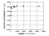
- 3 is a graph showing the relationship between the water flow density and the temperature gradient near the center of slab thickness in Experiment 2.
- 3 is a graph showing the relationship between water volume density and temperature drop time in Experiment 3.
- 3 is a graph showing the relationship between the average value of the solid fraction at the start of strong cooling and the temperature gradient near the center of slab thickness in Experiment 4. It is a graph showing the influence of reduction speed during strong cooling and light reduction on the degree of segregation.
- FIG. 1 is a schematic diagram showing an example of a continuous casting machine that is effective for implementing the continuous steel casting method according to the present invention.
- the continuous casting machine 11 illustrated in FIG. 1 is an example of a vertical bending type continuous casting machine.
- a curved type or completely vertical type continuous casting machine can also be used instead of the vertical bending type.
- the continuous casting machine 11 shown in FIG. 1 includes a mold 13, a tundish 14, a plurality of pairs of slab support rolls 16, a plurality of spray nozzles 17, and the like. As shown in this figure, the slab 18 is pulled out in the slab drawing direction D1.
- the tundish 14 side along the slab drawing direction D1 will be referred to as the upstream side, and the side from which the slab 18 is pulled out will be referred to as the downstream side in the following description.
- the tundish 14 is disposed above the mold 13 and is used to supply molten steel 12 to the mold 13.
- Molten steel 12 supplied from a ladle (not shown) is stored in this tundish 14.
- a sliding nozzle (not shown) for adjusting the flow rate of the molten steel 12 is installed at the bottom of the tundish 14, and an immersion nozzle 15 is installed at the bottom of this sliding nozzle.
- the continuous casting mold 13 is installed below the tundish 14, and molten steel 12 is injected into the mold 13 from the tundish 14 through an immersion nozzle 15.
- the injected molten steel 12 is cooled (primary cooling) in the mold 13, thereby forming the outer shell shape of the slab 18.
- a plurality of pairs of slab support rolls 16 are arranged to support the slab 18 from both sides along the slab drawing direction D1.
- the plurality of pairs of slab support rolls 16 are composed of a plurality of pairs of support rolls, for example, a pair of support rolls, a pair of guide rolls, and a pair of pinch rolls. Further, as shown in this figure, a plurality of pairs of slab support rolls 16 are assembled to form one segment 20.
- the plurality of spray nozzles 17 are arranged between adjacent slab support rolls 16 along the slab drawing direction D1. These spray nozzles 17 are nozzles for secondary cooling of the slab 18 by spraying cooling water toward the slab 18 .
- a nozzle such as a water spray nozzle (one-fluid spray nozzle) or an air mist spray nozzle (two-fluid spray nozzle) can be used.
- the slab 18 is cooled by cooling water (secondary cooling water) sprayed from the plurality of spray nozzles 17 while being pulled out along the slab drawing direction D1.
- cooling water secondary cooling water
- FIG. 1 the unsolidified portion 18a of molten steel in the slab 18 is shown with diagonal lines.
- FIG. 1 the solidification completion position where the unsolidified portion 18a is eliminated and solidification is completed is indicated by the reference numeral 18b.
- the downstream part of this continuous casting machine 11 is a light rolling zone 19 that lightly rolls down the slab 18.
- This light reduction band 19 is provided with a plurality of segments 20a and 20b each of which is constituted by a plurality of pairs of slab support rolls 16.
- the plurality of slab support rolls 16 of this light reduction band 19 are arranged so that the roll interval in the thickness direction of the slab 18 of each roll pair gradually narrows toward the slab drawing direction D1. , the slab 18 passing through the light rolling zone 19 is lightly rolled down.
- the reference numeral 22 in FIG. 1 indicates a lower correction position provided within the area of the light compression zone 19.
- a plurality of transport rolls 21 for transporting the completely solidified slab 18 are provided downstream of the horizontal band area A1.
- a slab cutting machine (not shown) that cuts the slab 18 into a predetermined length is disposed above the conveyance roll 21 .
- the solid phase rate along the thickness direction in the final solidified part in the width direction has the lowest solid phase rate in the width direction of the slab. From the starting point where the average value of is within the range of 0.8 or less, particularly 0.1 or more and 0.8 or less, the section up to the end point in which the average value of the solid phase ratio is larger than the average value of the solid phase ratio at the starting point and within the range of 1.0 or less is defined as the first section.
- a section following the first section is referred to as a second section, and this second section refers to a state where the surface temperature state (nucleate boiling state) cooled in the first section has a central solid fraction of 1.0. This is the interval that is complemented until .
- the slab is cooled by water spray sprayed from a water spray nozzle in the first section, and at this time, the water density per slab surface area is set to 50 L/(m 2 ⁇ min) or more and 2000 L/(m 2 ⁇ min) or less.
- the temperature gradient at the center of the thickness of the slab is greatly increased, the solidification structure at the center of the thickness of the slab is refined, and center segregation can be efficiently reduced.
- the slab is cooled with cooling water, with the water density per slab surface area being within the range of 50 L/(m 2 ⁇ min) to 2000 L/(m 2 ⁇ min). This is called "strong cooling.”
- FIG. 2 is a diagram in which the final solidified portion position in the width direction where the solid phase ratio is lowest in the width direction of the slab is defined as C1.
- FIG. 2 shows a plan view of the slab 18 when the upper and lower surfaces of the slab 18 are supported by slab support rolls 16.
- the direction “rear ⁇ front” corresponds to the slab drawing direction D1
- the direction “right ⁇ left” corresponds to the width direction D2 of the slab 18.
- the position C1 of the final solidified portion in the width direction where the solid fraction is lowest in the width direction of the slab is located along the slab drawing direction D1 at a position near the center of the slab 18 in the width direction.
- FIG. 3 is a cross-sectional view of the slab 18 cut along a plane perpendicular to the slab drawing direction D1.
- the direction “left ⁇ right” corresponds to the width direction D2 of the slab 18, and the direction “top ⁇ bottom” corresponds to the thickness direction D3 of the slab 18.
- the position C2 in the thickness direction of the final solidified part in the width direction with the lowest solid phase ratio in the width direction of the slab is a position parallel to the thickness direction D3 at C1 in the cross section of the slab 18, and is shown in FIG. Indicated by a broken line.
- the heat transfer coefficient for cooling from the slab surface by water spray is calculated using a regression equation
- the physical property values for other steels are calculated using the physical property values corresponding to each temperature from the data book.
- the heat transfer coefficient on the slab surface due to water spray is, for example, Publication 2 (Masashi Mitsuka, Tetsu to Hagane, Vol. 91, 2005, p. 685-693, Japan Iron and Steel Institute)
- Publication 3 Toshio Teshima et al., Tetsu to Hagane, Vol. 74, 1988, p. 1282-1289, Japan Iron and Steel Institute
- the solidus ratio at a certain position arbitrarily selected in the thickness direction of the slab cross section is calculated using the temperature at the arbitrarily selected position, the solidus temperature of molten steel, and the liquidus temperature of molten steel.
- the temperature at the arbitrarily selected position was determined using the above-mentioned cross-sectional temperature distribution of the slab. Also, when the temperature at that location is below the solidus temperature of molten steel, the solidus fraction is 1.0, and when the temperature at that location is above the liquidus temperature of molten steel, the solidus fraction is 0. be. Furthermore, when the temperature at that position is higher than the solidus temperature of molten steel and lower than the liquidus temperature of molten steel, the solidus fraction is greater than 0 and smaller than 1.0. It is determined by the temperature at that location.
- the water density per slab surface area is set to 50 L/(m 2 ⁇ min) or more and 2000 L/(m 2 ⁇ min) or less. within the range of In order to more efficiently obtain the effect of reducing segregation, the water density per slab surface area in this first section is more preferably 300 L/(m 2 ⁇ min) or more. Furthermore, according to the findings of the inventors, within this first section, when the water density per slab surface area is 2000L/(m 2 ⁇ min) and when it is 1000L/(m 2 ⁇ min), It was found that there were no significant differences in the temperature gradient at the final stage of solidification or the number of segregated grains. In addition, if the water density is reduced, the required amount of water can be reduced and the cost can be reduced, so it is desirable to set it to 1000 L/(m 2 ⁇ min) or less.
- the effect of the present invention can be obtained if the slab is cooled with the water volume density that is compatible with the present invention. From the viewpoint of effectively obtaining the above effect, it is preferable that the difference in the solid fraction average value between the starting point and the ending point is 0.2 or more, and more preferably 0.4 or more.
- the starting point of the first section is located either in a horizontal band in which the slab is conveyed horizontally within the continuous casting machine, or in a curved band located upstream of the horizontal band.
- the first section is within a region A1 of a horizontal band that horizontally conveys slabs in a continuous casting machine. The reason for this is that strong cooling within the horizontal band region allows uniform cooling and suppresses the influence of thermal stress, making it more difficult for internal cracks to occur in the slab.
- the starting point of the first section is a curved zone
- the effects of the present invention can be obtained, but there is a possibility that problems such as temperature drop and correction becoming impossible or cracking due to surface stress may occur.
- the starting point of the first section is located within the curved band, it is within the allowable range of the present invention.
- the flow rate is set to a flow rate that can maintain the surface temperature of the slab at 200°C or less at a water density per slab surface area that is smaller than the water density per slab surface area in the first section.
- the reason for this is that cooling with the same water density as in the first section would result in expensive equipment. However, by doing so, it is possible to suppress equipment investment costs and obtain the same effect as when strong cooling is performed only in the first section. Furthermore, it is possible to obtain the effect of suppressing rapid recuperation and preventing internal cracking of the slab due to recuperation.
- the water density per slab surface area is set within the range of 50 L/(m 2 ⁇ min) or more and 300 L/(m 2 ⁇ min) or less.
- the slab is cooled by spraying.
- the surface temperature of the slab refers to the temperature at the center of the width of the outermost surface of the slab, out of the cross-sectional temperature distribution of the slab determined by the above-mentioned unsteady heat transfer solidification analysis. Although this calculated value is used for the surface temperature in the present invention, the surface temperature of the slab can also be actually measured. When actually measuring the surface temperature, the temperature of the outermost surface of the slab is measured as the surface temperature using, for example, a radiation thermometer or a thermocouple.
- the roll opening degrees of the multiple pairs of slab support rolls were changed to a range that does not include the straightening point (starting after the upper straightening and ending before the lower straightening, and narrowing down the opening degree as much as possible by keeping the opening degree flat at the straightening point. (not) stepwise toward the downstream side, bulging the long sides of the slab with a total bulging amount of 2 to 20 mm, and then changing the roll opening of the multiple pairs of slab supporting rolls toward the downstream side in the casting direction. Further improvement in efficiency can be expected by reducing the amount in stages and lightly reducing the amount to a total amount that is less than the short side heat shrinkage.
- medium-carbon aluminum killed steel was cast using the vertical bending type continuous casting machine shown in Figure 1.
- the machine length of the continuous casting machine is 49 m
- the thickness of the slab is 250 mm
- the width of the slab is 2100 mm
- air mist spray is used for secondary cooling except for the first and second sections, and the range of secondary cooling is The distance was from just below the mold to the exit of the continuous casting machine.
- the chemical component concentration of medium carbon aluminum killed steel is 0.20% by mass of carbon (C), 0.25% by mass of silicon (Si), 1.1% by mass of manganese (Mn), and 0.0% by mass of phosphorus (P). 01% by mass and 0.002% by mass of sulfur (S) were used.
- the temperature gradient near the thickness center at the completed solidification position of the slab and at the final stage of solidification is defined as follows.
- the number of segregated grains, internal crack length, and roughness of the slab were measured as follows, and used to evaluate the degree of segregation, internal cracks, and roughness, respectively.
- “zaku” refers to voids that remain in the closed spaces between dendrites during solidification and appear as voids in the slab due to volumetric contraction of molten steel with concentrated segregated components during solidification.
- the average temperature of an area within a range of 1 mm in the thickness direction and 10 mm in the width direction from the center position of the slab was calculated in the cross section of the slab 1 m upstream in the slab drawing direction D1 from the solidification completion position.
- the cross section of the slab 1 m upstream in the slab drawing direction D1 from the solidification completion position with a position 10 mm in the thickness direction from the center position of the slab, ⁇ 1 mm in the thickness direction and 10 mm in the width direction
- the average temperature in the area within the range was calculated, and the difference between these two average temperatures was divided by 10 mm, which was taken as the temperature gradient (K/mm) near the center of the thickness of the slab at the final stage of solidification.
- the slab perpendicular to the slab drawing direction D1 In the cross section of the slab perpendicular to the slab drawing direction D1, it has a width of 15 mm, includes a central segregation part in the center, and has a triple point on one side from the center of the width (solidified shells on the short side and long side have grown).
- a slab sample with a length up to the point where the specimen met was taken.
- the cross section of the collected slab sample perpendicular to the slab drawing direction D1 is polished, and the surface is corroded with a saturated aqueous solution of picric acid to reveal a segregation zone, and the slab thickness is ⁇ 7 from the center of the segregation zone.
- the range of .5 mm was defined as the central segregation area.
- the slab sample in the segregation zone near the center of the thickness (near the solidified part) into small pieces in the width direction of the slab was divided into pieces with an electron beam diameter of 100 ⁇ m using an Electron Probe Micro Analyzer (EPMA).
- the manganese (Mn) concentration of the sample was analyzed over the entire surface. Then, the distribution of manganese (Mn) segregation degree was determined, and those in which regions with Mn segregation degree of 1.33 or more were connected were defined as one segregated grain.
- the number of segregated grains was counted, and the number of segregated grains divided by the length of the sample in the width direction of the slab was defined as the number of segregated grains (pieces/mm).
- the Mn segregation degree is the Mn concentration in the segregated portion divided by the Mn concentration at a position 10 mm away from the center of thickness.
- the internal crack length (mm). If no internal cracks were confirmed, the internal crack length was set to 0.
- the water density per slab surface area should be 2000 L/(m 2 ⁇ min).
- it is preferably 1000 L/(m 2 ⁇ min) or less.
- the lower limit is 50 L/(m 2 ⁇ min) or more, more preferably 300 L/(m 2 ⁇ min) or more.
- the temperature drop time for the slab surface temperature to drop from 800°C to 300°C is 200 seconds. Therefore, it was found that the water density per slab surface area is preferably 50 L/(m 2 ⁇ min) or more. Furthermore, when the water density per slab surface area was greater than 2000 L/(m 2 ⁇ min), there was no significant change in the falling time.
- the water density per slab surface area, particularly in the first section be 2000 L/(m 2 ⁇ min) or less.
- the inventors also investigated the starting position of strong cooling that can effectively increase the temperature gradient at the center of the thickness of the slab.
- the slab is cooled by changing the conditions of the average solid fraction along the thickness direction of the slab at the start of intense cooling, and the average solid fraction at the start of intense cooling is The relationship between this value and the temperature gradient near the center of thickness of the slab at the final stage of solidification was investigated.
- the thickness of the slab was 250 mm
- the water density per slab surface area during strong cooling was 300 L/(m 2 ⁇ min)
- strong cooling was continued until the slab was completely solidified.
- FIG. 7 shows a graph plotting the results of the relationship between the average solid fraction at the start of strong cooling and the temperature gradient near the center of thickness at the final stage of solidification of the slab.
- Medium carbon aluminum killed steel was cast using a vertical bending type continuous casting machine shown in FIG.
- the machine length of the continuous casting machine is 49 m
- the thickness of the slab is 250 mm
- the width of the slab is 2100 mm
- air mist spray is used for secondary cooling except for the first and second sections, and the range of secondary cooling is The distance was from just below the mold to the exit of the continuous casting machine.
- the chemical component concentration of medium carbon aluminum killed steel is 0.20% by mass of carbon (C), 0.25% by mass of silicon (Si), 1.1% by mass of manganese (Mn), and 0.0% by mass of phosphorus (P). 01% by mass and 0.002% by mass of sulfur (S) were used.
- Example 1 the solid phase rate at the starting point in the "first section”, the solid phase rate at the end point, the water density per slab surface area (L/(m 2 ⁇ min)), the first section exit surface Temperature (°C), solid fraction at the start point in the “second section”, solid phase fraction at the end point, water density per slab surface area (L/(m 2 ⁇ min)), maximum surface temperature in the second section (°C) was investigated under the conditions shown in Table 1.
- the degree of segregation is evaluated when the number of segregated grains is 1.3 particles/mm or less as good, marked with " ⁇ ", and more than 1.3 particles/mm and less than 3.5 particles/mm as acceptable. , and 3.5 pieces/mm or more were judged as unacceptable and evaluated as " ⁇ ".
- the length of the internal crack is 1.0 mm or less, it is considered good and marked with " ⁇ ", if it is more than 1.0 mm but less than 10 mm, it is marked with " ⁇ ", and if it is 10 mm or more, it is marked as unacceptable, and marked with "x". It was evaluated by
- No. 1 to 7 and No. All of Nos. 10 to 14 are examples in which operations were carried out within the range of conditions required for the operation in the first section that are compatible with the present invention. As a result, both the segregation degree and internal crack evaluation were good.
- No. 1 shown as a comparative example No. 8 is an example in which the water volume density in the first section is off. 9 is an example in which the solid phase ratio at the starting point is off. No. 1 with low water density. In No. 8, the nucleate boiling state could not be maintained and the evaluation of the number of segregated grains and the evaluation of internal cracks were also poor.
- Example 2 In this example, the conditions required for the second section treatment in the present invention (water density per slab surface area (L/(m 2 ⁇ min)) and the second section maximum surface temperature (°C) were investigated. In this example, the conditions required for the second section were studied based on the conditions required for the first section of [Example 1] above.The conditions and results are summarized in Table 2. Each evaluation was performed in the same manner as in [Example 1].As is clear from Table 2, Nos. 20 to 26 satisfied the conditions of the present invention, while Nos. 27 and 28 were evaluated in this second section. Therefore, although Nos. 27 and 28 satisfy the conditions of the present invention required in the first section, evaluation of segregation degree and internal Both crack evaluations were slightly inferior to Nos. 20 to 26.
- Example 3 In this example, the temperature gradient (K/mm) at the center of the thickness of the slab at the end of solidification, the reduction rate (m/min) as a light reduction condition, and the total amount of bulging (mm) are determined in the first section and the second section described above.
- the conditions required for this are studied on the assumption that the conditions are compatible with the present invention.
- the conditions and results are summarized in Table 3.
- Each evaluation was performed in the same manner as in [Example 1]. As is clear from Table 3, No. Nos. 30 to 37 are all cases that are suitable as invention examples, and the evaluations of segregation degree and internal cracking were generally good. However, No. Regarding Nos.
- the present invention assumes that the water density per slab surface area in at least the first section is within a predetermined range, and the water density per slab surface area in the second section is adjusted as necessary. It was confirmed that continuous casting slabs can be effectively cooled by controlling the It has also been found that it is more desirable to consider the temperature gradient near the center of slab thickness at the final stage of solidification and the conditions of light reduction in the first and second sections.
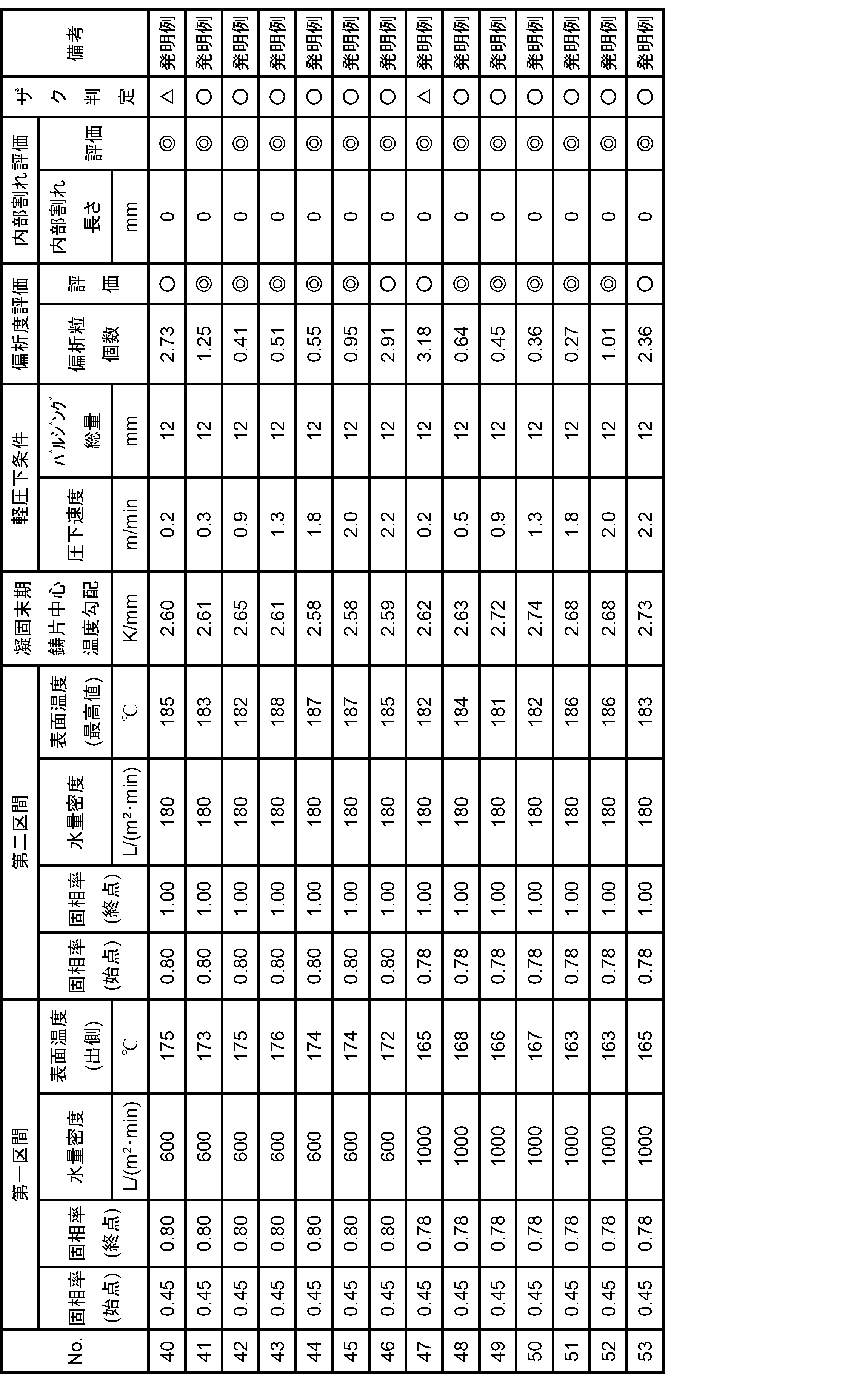
- Example 4 In this example, the cooling conditions required for the first section described above were set to a stronger cooling range, the cooling conditions required for the second section were set to 180 L/(m 2 ⁇ min), and the total amount of bulging was kept constant. The influence of rolling speed (m/min) was also investigated as a light rolling condition. The conditions and results are summarized in Table 4, and FIG. 8 shows the relationship between the reduction rate and the degree of segregation during light reduction. Each evaluation was performed in the same manner as in [Example 1]. In addition, for the evaluation of blemishes, those in which no blemishes were observed were evaluated as good ( ⁇ ), and those in which slight burrs were observed that did not affect the quality of the product were judged to be fair ( ⁇ ).
- the unit of volume “L” herein is 10 ⁇ 3 m 3 .
- “x to y” representing a range of numerical values represents a value greater than or equal to x and less than or equal to y, and includes boundary values.
Landscapes
- Engineering & Computer Science (AREA)
- Mechanical Engineering (AREA)
- Continuous Casting (AREA)
Abstract
Description
連続鋳造機内の鋳片引抜き方向に沿って、鋳片幅方向の最終凝固部での厚み方向に沿った固相率の平均値が0.8以下である始点から、前記鋳片幅方向の最終凝固部での厚み方向に沿った固相率の平均値が前記始点での固相率よりも大きくかつ1.0以下である終点までの範囲を第1区間とするとき、この第1区間内における鋳片表面積当たりの水量密度を、50L/(m2×min)以上2000L/(m2×min)以下の範囲内で、鋳片の冷却を行うことを特徴とする、鋼の連続鋳造方法。
(1)前記終点での幅方向の固相率の平均値が1.0以下である、前記第1区間よりも下流に位置する区間を第2区間とするとき、この第2区間における、鋳片表面積当たりの水量密度を50L/(m2×min)以上300L/(m2×min)以下の範囲内にて鋳片の冷却を行うこと、
(2)少なくとも、前記第1区間の終了時点から第2区間通過の間においては、鋳片の表面温度が200℃以下である核沸騰状態を維持しながら鋳造し、凝固末期における鋳片厚み中心付近の温度勾配を1.7~3.5K/mmとすること、
(3)前記第1区間及び第2区間は、連続鋳造機内での水平方向セグメント、もしくは垂直方向セグメントに限定する領域内に設置すること、
(4)前記第1区間及び第2区間において、軽圧下を付与し、0.3~2.0mm/minの圧下速度で、鋳片長辺面を圧下すること、
(5)複数対の鋳片支持ロールのロール開度を鋳造方向下流側に向かって段階的に増加させることにより、鋳片長辺面を2~20mmのバルジング総量でバルジングさせ、その後、複数対の鋳片支持ロールのロール開度を鋳造方向下流側に向かって段階的に減少させて鋳片を軽圧下すること。
鋳片の凝固完了位置は、非定常伝熱凝固解析によって算出した。
凝固末期における鋳片の厚み中心付近の温度勾配は、上述した非定常伝熱凝固解析を用いて算出した。
偏析粒個数は以下の方法で測定し、偏析の評価に用いた。
鋳片の内部割れ長さを以下の方法で測定し、内部割れの評価に用いた。
完全凝固後の鋳片の鋳片引抜き方向D1に垂直な断面をフライス加工後、塩酸エッチングの後に、マクロプリントを採取し、目視の官能検査でザクを確認した。ザクが確認されなかったものを良好(○)とし、製品の品質に影響のない軽微なザクが確認されたものを可(△)と判定した。
[実験1]
この実験においては、鋳片の凝固末期における鋳片厚み中心付近の温度勾配と、偏析粒個数とを、上述した方法で算出または測定し、これらの関係を考察した。その結果をプロットしたグラフを図4に示した。図4に示す結果より、凝固末期における鋳片厚み中心付近の温度勾配(K/mm)を大きくすると、偏析粒個数が少なくなって、中心偏析を低減できる傾向のあることが分かった。凝固末期における鋳片厚み中心付近の温度勾配としては1.7~3.5、より好ましくは2.0~3.5である。中心偏析を低減できる理由は、温度勾配を大きくすることによって、鋳片厚み中心部の凝固組織を微細化することができたためであると考えられる。
この実験においては、連続鋳造機を用いて鋳片を二次冷却する際に、水スプレーでの鋳片表面積当たりの水量密度の条件を変更して鋳片を製造し、当該水量密度と、鋳片の凝固末期における厚み中心付近の温度勾配との関係を調べた。そして、中心偏析を低減できる鋳片厚み中心部の温度勾配を実現するために最適な水量密度の範囲についても調べた。その結果をプロットしたグラフを図5に示した。
この実験では、鋳片冷却の効果について検討した。発明者らの知見では、鋳片冷却の効果は、鋳片の表面温度が大きく影響を及ぼしていることが分かった。これは鋳片表面温度により冷却水の沸騰形態が変化するためであると考えられる。鋳片の表面温度が十分に降下していれば、表層での沸騰形態は核沸騰となり、安定的な冷却が実現できる。そこで、連続鋳造機を用いて鋳片を二次冷却する際に、水スプレーでの鋳片表面積当たりの水量密度の条件を変更して、鋳片の表面温度が800℃から300℃まで降下するまでに費やした時間(温度降下時間)を計算し、温度降下時間に及ぼす水量密度の影響を調査した。これらの結果をプロットしたグラフを図6に示す。
次に、発明者らは、鋳片厚み中心部の温度勾配を効率的に大きくすることができる強冷却の開始位置についても調査した。連続鋳造機を用いて、強冷却開始時での、鋳片の厚み方向に沿った固相率の平均値の条件を変化させて鋳片を冷却し、強冷却開始時での固相率平均値と、鋳片の凝固末期における厚み中心付近の温度勾配との関係を調べた。鋳片の厚さは250mmであり、強冷却での鋳片表面積当たりの水量密度は300L/(m2×min)であり、強冷却は鋳片の完全凝固位置まで継続した。強冷却開始時での固相率平均値と、鋳片の凝固末期における厚み中心付近の温度勾配との関係について、その結果をプロットしたグラフを図7に示す。
図1に示した垂直曲げ型の連続鋳造機を用い、中炭素アルミキルド鋼を鋳造した。連続鋳造機の機長は49m、鋳片の厚さは250mm、鋳片の幅は2100mm、二次冷却は、第1区間及び第2区間を除き、エアーミストスプレーを用い、二次冷却の範囲は鋳型直下から連続鋳造機の出口までとした。中炭素アルミキルド鋼の化学成分濃度は、炭素(C)が0.20質量%、ケイ素(Si)が0.25質量%、マンガン(Mn)が1.1質量%、リン(P)が0.01質量%、硫黄(S)が0.002質量%のものを用いた。
この実施例においては、「第1区間」における始点での固相率、終点での固相率、鋳片表面積当たりの水量密度(L/(m2×min))、第1区間出側表面温度(℃)、および「第2区間」における始点での固相率、終点での固相率、鋳片表面積当たりの水量密度(L/(m2×min))、第2区間最高表面温度(℃)について、表1に示すような条件を与えて調べた。

この実施例は、本発明における第2区間の処理として求められる条件(鋳片表面積当たりの水量密度(L/(m2×min))、第2区間最高表面温度(℃)について検討した。即ち、この例では、上記[例1]の第1区間に求められる条件を前提とした上で、第2区間で求められる条件について検討したものである。その条件および結果について表2にまとめた。各評価は[例1]と同様に行った。この表2から明らかなとおり、No.20~26については本発明条件を満足する一方、No.27、28については、この第2区間で求められている鋳片表面積当たりの水量密度が不足している。そのため、No.27、28は、第1区間で求められている本発明の条件は満足しているものの、偏析度の評価および内部割れの評価とも、No.20~26に比べるとやや劣るという結果になった。

この実施例は、凝固末期の鋳片厚み中心部の温度勾配(K/mm)、軽圧下条件として圧下速度(m/min)、バルジング総量(mm)に関して、前述した第1区間、第2区間に求められる条件については本発明に適合することを前提とした例について検討したものである。その条件および結果について表3にまとめた。各評価は[例1]と同様に行った。この表3から明らかなとおり、No.30~37は、いずれも発明例として適合する場合であり、偏析度の評価、内部割れの評価とも概ね良好であった。しかし、No.38、39については第2区間の水量密度が不足するために凝固末期における鋳片厚み中心付近の温度勾配(K/mm)が小となり、また第2区間最高表面温度も高く(>200℃)なった。そのため、No.38、39は、No.30~37と同様の効果までは得られないことが分かった。

この実施例は、前述した第1区間に求められる冷却条件をより強冷却の範囲とし、第2区間に求められる冷却条件を180L/(m2×min)とし、バルジング総量を一定とした。そして、軽圧下条件として圧下速度(m/min)の影響を検討したものである。その条件および結果について表4にまとめ、図8に軽圧下時の圧下速度と偏析度との関係を示した。各評価は[例1]と同様に行った。また、ザクの判定は、ザクが確認されなかったものを良好(○)とし、製品の品質に影響のない軽微なザクが確認されたものを可(△)と判定した。この表4から明らかなとおり、No.41~45、48~52は、いずれも発明例として適合する場合であり、偏析度の評価およびザク判定の評価とも概ね良好であった。しかし、No.40および47については、軽圧下条件として圧下速度が過小のため、偏析粒個数が、No.41~45、48~52より多くなり、軽微なザクが見られた。一方、No.46および53については、軽圧下条件として圧下速度が過大のため、偏析粒個数が、No.41~45、48~52より多くなった。なお、表4の条件で内部割れの発生はなかった。この結果から、図8に示すように、第1区間の冷却条件をより強冷却の範囲とし、軽圧下条件として圧下速度を0.3~2.0m/minとすることで偏析度の評価、内部割れおよびザク判定の評価に優れた鋳片を製造できることが判った。
12 溶鋼
13 鋳型
14 タンディッシュ
15 浸漬ノズル
16 鋳片支持ロール
17 スプレーノズル
18 鋳片
18a 鋳片内の未凝固部
18b 凝固完了位置
19 軽圧下帯
20 セグメント
20a セグメント
20b セグメント
21 搬送ロール
Claims (6)
- 連続鋳造機内の鋳片引抜き方向に沿って、鋳片幅方向の最終凝固部での厚み方向に沿った固相率の平均値が0.8以下である始点から、前記鋳片幅方向の最終凝固部での厚み方向に沿った固相率の平均値が前記始点での固相率よりも大きくかつ1.0以下である終点までの範囲を第1区間とするとき、この第1区間内における鋳片表面積当たりの水量密度を、50~2000L/(m2×min)の範囲内で、鋳片の冷却を行う、鋼の連続鋳造方法。
- 前記終点での幅方向の固相率の平均値が1.0以下である、前記第1区間よりも下流に位置する区間を第2区間とするとき、この第2区間における、鋳片表面積当たりの水量密度を50~300L/(m2×min)の範囲内にて鋳片の冷却を行う、請求項1に記載の鋼の連続鋳造方法。
- 少なくとも、前記第1区間の終了時点から第2区間通過の間においては、鋳片の表面温度が200℃以下である核沸騰状態を維持しながら鋳造し、凝固末期における鋳片厚み中心付近の温度勾配を1.7~3.5K/mmとする、請求項1または2に記載の鋼の連続鋳造方法。
- 前記第1区間及び第2区間は、連続鋳造機内での水平方向セグメント、もしくは垂直方向セグメントに限定する領域内に設置する、請求項1~3にいずれか1に記載の鋼の連続鋳造方法。
- 前記第1区間及び第2区間において、軽圧下を付与し、0.3~2.0mm/minの圧下速度で、鋳片長辺面を圧下する、請求項1~4のいずれか1に記載の鋼の連続鋳造方法。
- 複数対の鋳片支持ロールのロール開度を鋳造方向下流側に向かって段階的に増加させることにより、鋳片長辺面を2~20mmのバルジング総量でバルジングさせ、その後、複数対の鋳片支持ロールのロール開度を鋳造方向下流側に向かって段階的に減少させて鋳片を軽圧下する、請求項1~5のいずれか1に記載の鋼の連続鋳造方法。
Priority Applications (5)
| Application Number | Priority Date | Filing Date | Title |
|---|---|---|---|
| CN202380030669.2A CN119053396A (zh) | 2022-03-28 | 2023-03-23 | 钢的连续铸造方法 |
| KR1020247034145A KR20240162540A (ko) | 2022-03-28 | 2023-03-23 | 강의 연속 주조 방법 |
| US18/730,104 US20250144702A1 (en) | 2022-03-28 | 2023-03-23 | Steel continuous casting method |
| EP23780029.7A EP4450185A4 (en) | 2022-03-28 | 2023-03-23 | Method for continuous casting of steel |
| JP2023538740A JP7355285B1 (ja) | 2022-03-28 | 2023-03-23 | 鋼の連続鋳造方法 |
Applications Claiming Priority (2)
| Application Number | Priority Date | Filing Date | Title |
|---|---|---|---|
| JP2022051592 | 2022-03-28 | ||
| JP2022-051592 | 2022-03-28 |
Publications (1)
| Publication Number | Publication Date |
|---|---|
| WO2023190018A1 true WO2023190018A1 (ja) | 2023-10-05 |
Family
ID=88202026
Family Applications (1)
| Application Number | Title | Priority Date | Filing Date |
|---|---|---|---|
| PCT/JP2023/011463 Ceased WO2023190018A1 (ja) | 2022-03-28 | 2023-03-23 | 鋼の連続鋳造方法 |
Country Status (1)
| Country | Link |
|---|---|
| WO (1) | WO2023190018A1 (ja) |
Citations (7)
| Publication number | Priority date | Publication date | Assignee | Title |
|---|---|---|---|---|
| JPH08132203A (ja) | 1994-11-10 | 1996-05-28 | Sumitomo Metal Ind Ltd | 連続鋳造方法 |
| JPH08192256A (ja) | 1995-01-12 | 1996-07-30 | Nippon Steel Corp | 連続鋳造方法 |
| JPH08224650A (ja) | 1995-02-22 | 1996-09-03 | Nippon Steel Corp | 鋼の連鋳鋳片の偏析、センターポロシティ改善方法 |
| JP2008100249A (ja) | 2006-10-18 | 2008-05-01 | Nippon Steel Corp | 鋼の連続鋳造方法及び連続鋳造設備 |
| JP2016028827A (ja) | 2014-07-25 | 2016-03-03 | Jfeスチール株式会社 | 鋼の連続鋳造方法 |
| JP2019155419A (ja) * | 2018-03-13 | 2019-09-19 | 日本製鉄株式会社 | 鋳片の連続鋳造方法 |
| WO2020203715A1 (ja) * | 2019-04-02 | 2020-10-08 | Jfeスチール株式会社 | 鋼の連続鋳造方法 |
-
2023
- 2023-03-23 WO PCT/JP2023/011463 patent/WO2023190018A1/ja not_active Ceased
Patent Citations (7)
| Publication number | Priority date | Publication date | Assignee | Title |
|---|---|---|---|---|
| JPH08132203A (ja) | 1994-11-10 | 1996-05-28 | Sumitomo Metal Ind Ltd | 連続鋳造方法 |
| JPH08192256A (ja) | 1995-01-12 | 1996-07-30 | Nippon Steel Corp | 連続鋳造方法 |
| JPH08224650A (ja) | 1995-02-22 | 1996-09-03 | Nippon Steel Corp | 鋼の連鋳鋳片の偏析、センターポロシティ改善方法 |
| JP2008100249A (ja) | 2006-10-18 | 2008-05-01 | Nippon Steel Corp | 鋼の連続鋳造方法及び連続鋳造設備 |
| JP2016028827A (ja) | 2014-07-25 | 2016-03-03 | Jfeスチール株式会社 | 鋼の連続鋳造方法 |
| JP2019155419A (ja) * | 2018-03-13 | 2019-09-19 | 日本製鉄株式会社 | 鋳片の連続鋳造方法 |
| WO2020203715A1 (ja) * | 2019-04-02 | 2020-10-08 | Jfeスチール株式会社 | 鋼の連続鋳造方法 |
Non-Patent Citations (1)
| Title |
|---|
| TOSHIO TESHIMA ET AL.: "Tetsu-to-Hagane", vol. 74, 1988, THE IRON AND STEEL INSTITUTE OF JAPAN, pages: 1282 - 1289 |
Similar Documents
| Publication | Publication Date | Title |
|---|---|---|
| JP7004086B2 (ja) | 鋼の連続鋳造方法 | |
| JP6115735B2 (ja) | 鋼の連続鋳造方法 | |
| JP6384679B2 (ja) | 熱延鋼板の製造方法 | |
| CN105598407A (zh) | 提高铸坯中心致密度的方法 | |
| JP5444807B2 (ja) | 連続鋳造鋳片の表面割れ防止方法 | |
| JP2000042700A (ja) | 鋼片の水冷方法および水冷用水槽 | |
| EP3981526A1 (en) | Secondary cooling method and device for continuously cast slab | |
| US6905558B2 (en) | Billet by continuous casting and manufacturing method for the same | |
| JP2002086252A (ja) | 連続鋳造方法 | |
| JPH09285856A (ja) | 連続鋳造方法 | |
| JP3401785B2 (ja) | 連続鋳造における鋳片の冷却方法 | |
| JP7355285B1 (ja) | 鋼の連続鋳造方法 | |
| JPH038864B2 (ja) | ||
| WO2023190018A1 (ja) | 鋼の連続鋳造方法 | |
| JP6788232B2 (ja) | 鋼の連続鋳造方法 | |
| JP2000237858A (ja) | 連続鋳造方法 | |
| RU2779384C1 (ru) | Способ непрерывной разливки стали | |
| JP2950152B2 (ja) | スラブ用連続鋳造鋳型 | |
| JPH078421B2 (ja) | 連続鋳造方法 | |
| JPH0436776B2 (ja) | ||
| CN101351285B (zh) | 用于连铸的方法和装置 | |
| JP2018171650A (ja) | 鋼板の製造方法 | |
| JP7644344B2 (ja) | スラブ鋳片の連続鋳造方法 | |
| JP2001137901A (ja) | 連続鋳造鋳片のホットチャージ圧延方法 | |
| JP2016179490A (ja) | 連続鋳造方法 |
Legal Events
| Date | Code | Title | Description |
|---|---|---|---|
| WWE | Wipo information: entry into national phase |
Ref document number: 2023538740 Country of ref document: JP |
|
| 121 | Ep: the epo has been informed by wipo that ep was designated in this application |
Ref document number: 23780029 Country of ref document: EP Kind code of ref document: A1 |
|
| WWE | Wipo information: entry into national phase |
Ref document number: 18730104 Country of ref document: US |
|
| ENP | Entry into the national phase |
Ref document number: 2023780029 Country of ref document: EP Effective date: 20240716 |
|
| REG | Reference to national code |
Ref country code: BR Ref legal event code: B01A Ref document number: 112024016987 Country of ref document: BR |
|
| WWE | Wipo information: entry into national phase |
Ref document number: 202417065296 Country of ref document: IN |
|
| WWE | Wipo information: entry into national phase |
Ref document number: 202380030669.2 Country of ref document: CN |
|
| ENP | Entry into the national phase |
Ref document number: 20247034145 Country of ref document: KR Kind code of ref document: A |
|
| WWE | Wipo information: entry into national phase |
Ref document number: 1020247034145 Country of ref document: KR |
|
| NENP | Non-entry into the national phase |
Ref country code: DE |
|
| ENP | Entry into the national phase |
Ref document number: 112024016987 Country of ref document: BR Kind code of ref document: A2 Effective date: 20240820 |
|
| WWP | Wipo information: published in national office |
Ref document number: 18730104 Country of ref document: US |