WO2023190367A1 - センサー配置決定装置およびセンサー配置決定方法 - Google Patents
センサー配置決定装置およびセンサー配置決定方法 Download PDFInfo
- Publication number
- WO2023190367A1 WO2023190367A1 PCT/JP2023/012255 JP2023012255W WO2023190367A1 WO 2023190367 A1 WO2023190367 A1 WO 2023190367A1 JP 2023012255 W JP2023012255 W JP 2023012255W WO 2023190367 A1 WO2023190367 A1 WO 2023190367A1
- Authority
- WO
- WIPO (PCT)
- Prior art keywords
- sensor
- information
- space
- placement
- air conditioner
- Prior art date
- Legal status (The legal status is an assumption and is not a legal conclusion. Google has not performed a legal analysis and makes no representation as to the accuracy of the status listed.)
- Ceased
Links
Images







Classifications
-
- F—MECHANICAL ENGINEERING; LIGHTING; HEATING; WEAPONS; BLASTING
- F24—HEATING; RANGES; VENTILATING
- F24F—AIR-CONDITIONING; AIR-HUMIDIFICATION; VENTILATION; USE OF AIR CURRENTS FOR SCREENING
- F24F11/00—Control or safety arrangements
- F24F11/30—Control or safety arrangements for purposes related to the operation of the system, e.g. for safety or monitoring
-
- F—MECHANICAL ENGINEERING; LIGHTING; HEATING; WEAPONS; BLASTING
- F24—HEATING; RANGES; VENTILATING
- F24F—AIR-CONDITIONING; AIR-HUMIDIFICATION; VENTILATION; USE OF AIR CURRENTS FOR SCREENING
- F24F11/00—Control or safety arrangements
- F24F11/30—Control or safety arrangements for purposes related to the operation of the system, e.g. for safety or monitoring
- F24F11/46—Improving electric energy efficiency or saving
-
- F—MECHANICAL ENGINEERING; LIGHTING; HEATING; WEAPONS; BLASTING
- F24—HEATING; RANGES; VENTILATING
- F24F—AIR-CONDITIONING; AIR-HUMIDIFICATION; VENTILATION; USE OF AIR CURRENTS FOR SCREENING
- F24F11/00—Control or safety arrangements
- F24F11/89—Arrangement or mounting of control or safety devices
-
- G—PHYSICS
- G01—MEASURING; TESTING
- G01N—INVESTIGATING OR ANALYSING MATERIALS BY DETERMINING THEIR CHEMICAL OR PHYSICAL PROPERTIES
- G01N33/00—Investigating or analysing materials by specific methods not covered by groups G01N1/00 - G01N31/00
- G01N33/0004—Gaseous mixtures, e.g. polluted air
- G01N33/0009—General constructional details of gas analysers, e.g. portable test equipment
- G01N33/0073—Control unit therefor
- G01N33/0075—Control unit therefor for multiple spatially distributed sensors, e.g. for environmental monitoring
-
- G—PHYSICS
- G05—CONTROLLING; REGULATING
- G05B—CONTROL OR REGULATING SYSTEMS IN GENERAL; FUNCTIONAL ELEMENTS OF SUCH SYSTEMS; MONITORING OR TESTING ARRANGEMENTS FOR SUCH SYSTEMS OR ELEMENTS
- G05B15/00—Systems controlled by a computer
- G05B15/02—Systems controlled by a computer electric
-
- F—MECHANICAL ENGINEERING; LIGHTING; HEATING; WEAPONS; BLASTING
- F24—HEATING; RANGES; VENTILATING
- F24F—AIR-CONDITIONING; AIR-HUMIDIFICATION; VENTILATION; USE OF AIR CURRENTS FOR SCREENING
- F24F2110/00—Control inputs relating to air properties
- F24F2110/50—Air quality properties
- F24F2110/64—Airborne particle content
-
- F—MECHANICAL ENGINEERING; LIGHTING; HEATING; WEAPONS; BLASTING
- F24—HEATING; RANGES; VENTILATING
- F24F—AIR-CONDITIONING; AIR-HUMIDIFICATION; VENTILATION; USE OF AIR CURRENTS FOR SCREENING
- F24F2120/00—Control inputs relating to users or occupants
- F24F2120/10—Occupancy
-
- G—PHYSICS
- G05—CONTROLLING; REGULATING
- G05B—CONTROL OR REGULATING SYSTEMS IN GENERAL; FUNCTIONAL ELEMENTS OF SUCH SYSTEMS; MONITORING OR TESTING ARRANGEMENTS FOR SUCH SYSTEMS OR ELEMENTS
- G05B2219/00—Program-control systems
- G05B2219/20—Pc systems
- G05B2219/26—Pc applications
- G05B2219/2614—HVAC, heating, ventillation, climate control
Definitions
- It relates to a sensor placement determination device and a sensor placement determination method.
- the temperature at a predetermined position is predicted using the value of an environmental sensor installed in a space, and the predicted temperature is used to control an air conditioner (Patent Document 1 (Japanese Patent No. 3,548,114)).
- the accuracy of predicting the temperature at a given location may decrease, and the air conditioner may not be able to be controlled appropriately.
- the sensor placement determining device is a sensor placement determining device that determines the placement of sensors that measure the environment in a space, and includes an acquisition unit and a determining unit.
- the acquisition unit acquires first information and second information.
- the first information is information that associates factors that affect the environment with the effects of distance from the factors that affect the environment.
- the second information is information regarding the arrangement of factors in space.
- the determining unit determines candidates for sensor placement in space based on the first information and the second information.
- This sensor placement determination device considers the influence of factors in the space on the environment and determines sensor placement candidates, making it possible to accurately predict the environment in the space using the placed sensors. I can do it.
- the sensor placement determining device of the second aspect is the device of the first aspect, and the second information includes information regarding at least one of a building design model, an analysis model, an architectural drawing, and an instrumentation drawing.
- This sensor placement determination device can acquire spatial information about buildings.
- the sensor placement determining device is the device according to the first aspect or the second aspect, and the factor that affects the environment is an air conditioner having an indoor unit.
- the first information is determined according to at least one of the following: the model of the air conditioner, the shape of the indoor unit, the capacity of the air conditioner, the volume of conditioned air supplied by the indoor unit, and the system information of the air conditioner; Contains information on the environmental impact depending on the distance from the indoor unit.
- candidates for sensor placement can be determined by taking into consideration the influence of the air conditioner on the environment within the space.
- the sensor placement determining device is the device according to the third aspect, and the first information is at least one of the wind direction, blowout temperature, blowout range, and wind speed of the conditioned air supplied by the indoor unit, and a combination thereof. It further includes information regarding the impact on the environment depending on the distance from the indoor unit, which is determined depending on the indoor unit.
- candidates for sensor placement can be determined in consideration of the influence of the conditioned air supplied by the indoor unit on the environment within the space.
- the sensor placement determining device is the device according to the first aspect or the second aspect, and the factor that affects the environment is a ventilation device.
- the first information is the model of the ventilation system, the shape of the ventilation system, the ventilation volume of the ventilation system, the volume of air supplied by the ventilation system, the presence or absence of a total heat exchanger, the heat exchange efficiency of the total heat exchanger, and the temperature of the ventilation system. It includes information regarding the impact on the environment depending on the distance from the ventilation device, which is determined depending on at least one of the presence or absence of an adjustment function and a combination thereof.
- candidates for sensor placement in a space can be determined in consideration of the influence of the ventilation system on the environment within the space.
- the sensor placement determining device is the device according to the first aspect or the second aspect, and the factors that influence the environment are fixtures.
- the first information includes information about the influence on the environment depending on the distance from the fixture, which is determined depending on the type of fixture.
- candidates for sensor placement can be determined by taking into account the influence of fixtures on the environment within the space.
- the sensor placement determining device is the device according to the first aspect or the second aspect, and the factor that influences the environment is a window.
- the first information is the impact on the environment depending on the distance from the window, which is determined depending on at least one of the window size, heat transmission coefficient, solar gain coefficient, and the presence or absence of a shield, or a combination thereof. .
- candidates for sensor placement can be determined by taking into consideration the influence of windows on the environment within the space.
- the sensor placement determining device of the eighth viewpoint is the device of the first viewpoint or the second viewpoint, and the factor that affects the environment is a door.
- the first information is the influence on the environment depending on the distance from the door, which is determined depending on at least one of the door size, heat insulation performance, and opening/closing frequency, and a combination thereof.
- candidates for sensor placement can be determined by taking into consideration the impact of the door on the environment within the space.
- the sensor placement determining device is a device according to the first aspect or the second aspect, and the determining unit calculates the volume or floor area of the space from the second information, and , determine the quantity of sensors to be placed in the space.
- this sensor placement determination device by determining the numerical values of the sensors in consideration of the size of the space, it is possible to reduce costs without arranging a large number of sensors.
- the sensor placement determining device is a device according to the third or fourth aspect, and the first information is determined according to the distance from the indoor unit, which is determined according to the quantity of indoor units or the quantity of refrigerant systems. Further includes information regarding environmental impacts.
- the determining unit determines the number of sensors to be arranged in the space according to the number of indoor units or the number of refrigerant systems.
- This sensor placement determining device can determine the number of sensors suitable for the space in which the indoor unit is installed by determining the numerical values of the sensors in consideration of the air conditioner information.
- the sensor placement determining device is the device according to any one of the first to ninth aspects, and the determining unit determines the number of sensors to be placed in the space according to the number of factors that affect the environment. Determine.
- This sensor placement determination device determines the sensor value by considering the number of factors that influence the space, so it is possible to determine the optimal value for the sensor regardless of the number of factors in the space. .
- the sensor placement determining device is the device according to any one of the first to eighth aspects, and further includes an output unit.
- the output unit outputs the candidate placement of the sensor in space determined by the determination unit.
- the output unit outputs the sensor placement candidates, so that the user can easily obtain the sensor placement candidates.
- the sensor placement determining device is the device according to the twelfth aspect, and includes a plurality of sensors arranged in a space with different purposes.
- the output unit distinguishes among a plurality of sensors having different purposes and outputs candidates for placement of the sensors in space.
- placement candidates can be obtained for each purpose-specific sensor.
- the sensor placement determining device is a device according to the twelfth or thirteenth aspect, and the determining unit is configured to select a position influenced by the distance from the factor or a position influenced by the distance from the factor for each purpose of arranging the sensor. Any position that is not affected by distance is determined as a candidate for sensor placement in space.
- the output unit outputs candidates for placement of the sensor in space or positions of inappropriate placement of the sensor in space for each purpose of placement of the sensor.
- this sensor placement determination device by acquiring the inappropriately placed positions of the sensors, it is possible to determine the sensor placement by taking the inappropriately placed positions into consideration.
- the sensor placement determining device is a device according to the thirteenth viewpoint or the fourteenth viewpoint, and the sensors having different purposes include a first sensor and a second sensor.
- the first sensor is always installed in the space.
- the second sensor is retrieved after acquiring data regarding the environment within the space.
- the output unit outputs a notification of the timing at which the second sensor is retrieved from the space or a notification of the timing at which data acquisition by the second sensor ends.
- the sensor placement determination method is a sensor placement determination method for determining the placement of sensors that measure the environment in a space, and includes an acquisition step and a determination step.
- the acquisition step acquires first information and second information.
- the first information is information that associates factors that affect the environment with the effects of distance from the factors that affect the environment.
- the second information is information regarding the arrangement of factors in space.
- the determining step determines candidates for sensor placement in space based on the first information and the second information.
- the environment in the space can be accurately predicted by determining sensor placement candidates in consideration of the influence of factors in the space on the environment.
- the sensor placement determination device includes an analysis section and a determination section.
- the analysis unit performs thermal airflow analysis of the space regarding the influence of factors that affect the environment within the space.
- the determining unit determines candidates for sensor installation in the space based on the results of the thermal airflow analysis of the space.
- This sensor placement determination device can accurately predict the environment in a space by determining sensor placement candidates in consideration of the results of thermal air flow analysis of the space.
- FIG. 2 is a functional block diagram of an air conditioning control system.
- FIG. 3 is a diagram showing an example of a target space. It is a figure showing an example of arrangement of an air conditioner in target space. It is a flow chart of an air conditioning control system.
- FIG. 3 is a diagram for explaining an example of air conditioner information and spatial information.
- FIG. 3 is a diagram for explaining an example of a location where a sensor is not always installed.
- FIG. 3 is a diagram for explaining an example of a sensor installation range.
- FIG. 7 is a diagram showing another example of the target space.
- FIG. 7 is a diagram illustrating another example of a location where it is inappropriate to always install a sensor.
- FIG. 7 is a diagram illustrating another example of a location where it is inappropriate to always install a sensor.
- the air conditioning control system 100 of this embodiment is a system provided to perform air conditioning control of a room, which is the target space 80. As shown in FIG. 1, the air conditioning control system 100 includes an air conditioner A and a sensor placement determining device 10.
- the air conditioning control system 100 of this embodiment corresponds to the sensor placement determining device 10.
- the sensor placement determining device 10 is a device for implementing the sensor placement candidate determining method described in the claims.
- the sensor placement determining device 10 communicates with equipment related to air conditioning of the target space 80 via the network 90.
- the device related to air conditioning of the target space 80 is the air conditioner A.
- Air conditioner A is an air conditioning indoor unit (indoor unit) installed in a space.
- the sensor placement determination device 10 determines sensor placement candidates in the target space 80.
- the sensors include a constant sensor S1 and a teacher data acquisition sensor S2.
- the sensor placement determining device 10 is realized by a computer.
- the sensor placement determination device 10 includes an acquisition section 20 and a determination section 30, as shown in FIG.
- the computer 10 includes a control calculation device and a storage device.
- a processor such as a CPU or a GPU can be used as the control calculation device.
- the control arithmetic device reads a program stored in the storage device, and performs predetermined image processing and arithmetic processing according to this program. Furthermore, the control calculation device can write calculation results to the storage device and read information stored in the storage device according to the program.
- the acquisition unit 20 and determination unit 30 shown in FIG. 1 are various functional blocks realized by a control calculation device. These functional blocks appear when the control arithmetic unit executes the program.
- the acquisition unit 20 acquires air conditioner information, which is information that associates factors that affect the environment within the target space 80 with the effects of distance from the factors that affect the environment within the target space 80.
- (First information) 21 is acquired.
- the environment within the target space 80 is temperature.
- the factor that affects the temperature is the air conditioner (indoor unit) A.
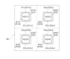
- the air conditioning control system 100 of this embodiment includes a plurality of air conditioners A1 to A4 in the target space 80.
- each of the plurality of air conditioners A1 to A4 is provided with four air outlets A1a to A4d along four sides.
- the air conditioners A1 to A4 have flaps 61a to 64d that adjust the direction of air blown out from the air outlets A1a to A4d.
- the air conditioner information 21 is information that associates the air conditioner A with the influence of the distance from the air conditioner A.
- the distance from the air conditioner A is small, the influence of the air conditioner A on the temperature within the target space 80 becomes large.
- the straight line distance from the air conditioner A is about 3 m or less, the influence of the air conditioner A on the temperature within the target space 80 will be large, but the straight line distance from the air conditioner A is not limited to this.
- the air conditioner information 21 includes the model of the air conditioner A, the shape of the indoor unit (air conditioner) A, the capacity of the air conditioner A, the volume of conditioned air supplied by the air conditioner A, and the refrigerant system information (system information) of the air conditioner A. , and information regarding the influence on temperature according to the distance from the air conditioner A, which is determined according to at least one of the following and combinations.
- the types of air conditioner A include room air conditioners for residences, air conditioners for stores or offices, multi-air conditioners for buildings, etc. Further, the shape of the indoor unit (air conditioner) A includes a ceiling-embedded cassette type, a ceiling-suspended type, a floor-standing type, and the like. In this embodiment, the indoor unit A has a ceiling-embedded cassette shape.
- the influence of the air conditioner A on the temperature within the target space 80 becomes large.
- the capacity of the air conditioner A is about 2.8 kW or more, the influence of the air conditioner A on the temperature within the target space 80 becomes large, but the capacity of the air conditioner A is not limited to this.
- the influence of air conditioner A on the temperature within target space 80 becomes large.
- the volume of conditioned air supplied by air conditioner A is approximately 300 m3/min or more, the influence of air conditioner A on the temperature within the target space 80 will be large; however, the volume of conditioned air supplied by air conditioner A will be It is not limited to this.
- the refrigerant system information of air conditioner A is information regarding the connection between the indoor unit and the outdoor unit. It is assumed that a plurality of indoor units connected to one outdoor unit by refrigerant piping belong to the same refrigerant system.
- the first refrigerant system has a first outdoor unit connected to a plurality of indoor units A1 to A4 through refrigerant piping
- the second refrigerant system has a second outdoor unit connected to a plurality of indoor units A5 to A8 (Fig. ) are connected by refrigerant piping.
- the refrigerant system information of air conditioner A includes information regarding which system the indoor unit belongs to among a plurality of refrigerant systems.
- the refrigerant system information of air conditioner A includes information that indoor units A1 to A4 belong to the first refrigerant system.
- the air conditioner information 21 is determined according to the distance from the air conditioner A, which is determined according to at least one of the following: wind direction, blowout temperature, blowout range, and wind speed of the conditioned air supplied by the air conditioner A. Information regarding the influence on temperature may also be included.
- the flaps 61a to 64d of the air conditioners (indoor units) A1 to A4 are placed inside the four outer circumferential sides of the bottom surface of one indoor unit A1 to A4 in parallel with each side. They are extended and provided at positions corresponding to the respective air outlets A1a to A4d.
- a control unit (not shown) controls to change the angle of each flap 61a to 64d of each indoor unit A with respect to each air outlet A1a to A4d, and directs the airflow to a predetermined position within the target space 80. I can do it.
- a fan (not shown) is provided in each of the indoor units A1 to A4, and the speed of the airflow sent out from the air outlets A1a to A4d is adjusted by a control unit.
- the air conditioners A1 to A4 blow out conditioned air from four directions of each outlet A1a to A4d.
- the air conditioners A1 to A4 may blow out conditioned air from, for example, any two directions among the air outlets A1a to A4d.
- the influence of the air conditioner A on the temperature in the target space 80 becomes greater depending on the direction in which conditioned air is blown out.
- the influence of air conditioner A on the temperature in target space 80 due to the outlet temperature of air conditioner A becomes large.
- the temperature difference between the outlet temperature of air conditioner A and the indoor temperature of target space 80 is about 10°C or more, the influence of air conditioner A on the temperature in target space 80 due to the outlet temperature of air conditioner A is large.
- the temperature difference between the blowout temperature of the air conditioner A and the indoor temperature of the target space 80 is not limited to this.
- the indoor units A1 to A4 can be operated by changing the blowing range of the indoor unit A in the range of 30 degrees to 90 degrees when viewed from the ceiling by changing the orientation of the flaps 61a to 64d.
- the influence of the air conditioner A on the temperature within the target space 80 becomes large.
- the wind speed of the indoor unit A is approximately 1 m/s or more at a distance of 0 m from the air outlet A1a to A4d of the air conditioner A, the influence of the air conditioner A on the temperature in the target space 80 becomes large;
- the wind speed of aircraft A is not limited to this.
- the acquisition unit 20 acquires spatial information (second information) 22 that is information regarding the arrangement of factors that affect the environment within the target space 80.
- the spatial information 22 is information regarding the arrangement of the air conditioner A in the target space 80.
- the space information 22 includes information regarding the design model 70 of the building in which the target space 80 is included.
- the acquisition unit 20 acquires information regarding the arrangement of the air conditioners A in the target space 80 of the building from the building design model 70.
- the spatial information 22 is not limited to the building design model 70, and may include information regarding at least one of a building analytical model, an architectural drawing, and an instrumentation drawing.
- the determination unit 30 determines the arrangement candidate 31 for the constant sensor S1 in the target space 80 and the teacher data acquisition sensor S2 in the target space 80 based on the air conditioner information 21 and the spatial information 22.
- the arrangement candidates 32 are determined.
- the determining unit 30 is based on air conditioner information 21 that associates the air conditioner A with the influence of the distance from the air conditioner A, and spatial information 22 regarding the arrangement of the air conditioner A within the target space 80. , a placement candidate 31 for the constant sensor S1 in the target space 80 and a placement candidate 32 for the teacher data acquisition sensor S2 in the target space 80 are determined.
- the determining unit 30 calculates the floor area of the target space 80 from the spatial information 22, and determines the quantity 33 of the constant sensors S1 to be arranged in the target space 80 according to the floor area of the target space 80.
- the determining unit 30 divides the target space 80 into several areas with a predetermined floor area based on the shape and size of the target space 80, the number of air conditioners A, and the accuracy of target temperature prediction, and divides the target space 80 into several areas with a predetermined floor area.
- the quantity 33 of the constant sensors S1 may be determined on the assumption that one constant sensor S1 is installed at a time.
- the determining unit 30 calculates the floor area of the target space 80 from the design model 70, and determines the quantity 33 of constant sensors S1 to be placed in the target space 80 according to the floor area of the target space 80. do. It is preferable that about one constant sensor S1 is disposed for every 100 m 2 to 150 m 2 of floor area of the target space 80. In this embodiment, one sensor S1 is always placed per 100 m 2 of floor area of the target space 80. For example, when the floor area of the target space 80 is 100 m 2 , the determining unit 30 determines that the number 33 of constant sensors S1 to be arranged in the target space 80 is “1”.
- the sensor is an environmental sensor that measures the environment within the target space 80.
- the sensors include a constant sensor S1 that is always installed in the target space 80, and a teacher data acquisition sensor S2 that is installed in the target space 80 when acquiring teacher data.
- the environment within the target space 80 includes temperature, humidity, carbon dioxide concentration, etc.
- Environmental sensors include temperature sensors, carbon dioxide sensors, humidity sensors, etc.
- the sensor is a temperature sensor.
- the constant sensor S1 is a temperature sensor for acquiring data regarding the temperature in the target space 80.
- the sensor S1 constantly acquires data regarding the temperature in the target space 80.
- the constant sensor S1 is always installed in the target space 80 before and during the actual operation of air conditioning control by the air conditioning control system 100.
- the constant sensor S1 is placed at a position determined by the sensor placement determining device 10 of the air conditioning control system 100.
- the constant sensor S1 is arranged at a location where the temperature in the target space 80 is less affected by the air conditioner A.
- the teacher data acquisition sensor S2 is a temperature sensor for acquiring teacher data regarding the temperature in the target space 80.
- the teacher data acquisition sensor S2 acquires teacher data regarding the temperature in the target space 80.
- a machine learning device uses training data to learn a soft sensing prediction model.
- the machine learning device learns by associating the value of the data of the constant sensor S1, which is an explanatory variable of the soft sensing prediction model, with the value of the teacher data of the teacher data acquisition sensor S2, which is the target variable of the soft sensing prediction model.
- the soft sensing prediction model uses the data value of the constant sensor S1 as an explanatory variable to predict the temperature at the position where the teacher data acquisition sensor S2 is installed.
- the teacher data acquisition sensor S2 is installed at a position (prediction position) where the temperature in the target space 80 is predicted using the soft sensing prediction model before the air conditioning control system 100 actually operates the air conditioning control.
- the teacher data acquisition sensor S2 is collected, and the created soft sensing prediction model is used to predict parameters (temperature) and applied to visualization of temperature distribution, air conditioning control, etc. .
- the teacher data acquisition sensor S2 is placed at a position determined by the sensor placement determining device 10 of the air conditioning control system 100.
- the teacher data acquisition sensor S2 is arranged, for example, at a position near a disturbance element that has a strong influence on the temperature in the target space 80.
- Disturbance elements that have a strong influence on the temperature in the target space 80 include the ventilation device B, the window D (see FIG. 8), and the like.
- the teacher data acquisition sensors S2 are uniformly arranged throughout the target space 80.
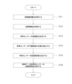
- FIG. 4 A flowchart of the air conditioning control system 100 is shown in FIG. In FIG. 4, an example will be described in which air conditioners A1 to A4 are arranged in the target space 80.
- step S11 the acquisition unit 20 acquires air conditioner information 21.
- the acquisition unit 20 acquires air conditioner information 21, which is information that associates the air conditioners A1 to A4 with the influence of distance from the air conditioners A1 to A4.
- the distance from the center position 4.0001 of the air conditioner A1 to the predetermined position P1 near the center of the target space 80 is d1.
- the distance from the center position 4.0002 of the air conditioner A2 to the predetermined position P1 near the center of the target space 80 is d2.
- the distance from the center position obviously3 of the air conditioner A3 to the predetermined position P1 near the center of the target space 80 is d3.
- the distance from the center position obviously4 of the air conditioner A4 to the predetermined position P1 near the center of the target space 80 is d4.
- the distance from the center position 4.0001 of the air conditioner A1 to the predetermined position P2 in the region 80c of the target space 80 is d5.
- the distance from the center position 4.0002 of the air conditioner A2 to the predetermined position P2 in the region 80c of the target space 80 is d6.
- the distance from the center position obviously3 of the air conditioner A3 to the predetermined position P2 in the region 80c of the target space 80 is d7.
- the distance from the center position whichever4 of the air conditioner A4 to the predetermined position P2 in the region 80c of the target space 80 is d8.
- the acquisition unit 20 acquires, as the air conditioner information 21, for example, information that associates the air conditioner A1 with a distance d1 from the center position schreib1 of the air conditioner A1 to a predetermined position P1 in the region 80a of the target space 80. After that, the process advances to step S12.
- step S12 the acquisition unit 20 acquires the spatial information 22.
- the second information 22 which is information regarding the arrangement of the air conditioners A1 to A4 in the target space 80 of the building, is obtained from the design drawing 70.
- the target space 80 includes regions 80a to 80d.
- the air conditioner A1 is arranged in a region 80a of the target space 80.
- Air conditioner A2 is arranged in region 80b of target space 80.
- Air conditioner A3 is arranged in region 80c of target space 80.
- the air conditioner A4 is arranged in a region 80d of the target space 80.
- step S13 the determining unit 30 determines the number 33 of constant sensors S1 to be installed.
- the target space 80 is divided into predetermined areas based on the air conditioner information 21 acquired in step S11 and the spatial information 22 acquired in step S12, and one sensor S1 is always installed in each area. As such, the number of installed sensors S1 at all times, 33, is determined.
- the determining unit 30 calculates the floor area of the target space 80 from the spatial information 22 acquired in step S12, and selects the constant sensor S1 to be placed in the target space 80 according to the floor area of the target space 80. Determine the quantity 33.
- the floor area of the target space 80 is a square of 100 m 2 with side L of 10 m and side M of 10 m. Therefore, the determining unit 30 determines that the number 31 of constantly installed sensors S1 in the target space 80 is "1". After that, the process advances to step S14.
- step S14 the determining unit 30 always extracts the position of the inappropriate placement of the sensor S1.
- the position where the sensor S1 is always inappropriately placed is within the reach of the airflow blown from the air conditioner A.
- the determining unit 30 estimates the maximum air volume of the air conditioner A and the reach range of the outlet airflow in each wind direction from the shape of the air conditioner (indoor unit) A, the capacity of the air conditioner A, and the air volume of the air conditioner A, and The reachable range of the blown airflow of A is always extracted as the position of the inappropriate placement of the sensor S1. Further, the reach range of the airflow blown from the air conditioner A may be estimated based on the physical distance from the air conditioner A.
- the reachable range of the airflow from the air conditioner A is approximately 0 m to about 3 m from the air outlet of the air conditioner A, but the reachable range of the airflow from the air conditioner A is not limited to this.
- FIG. 6 is a diagram for explaining an example of a location where the permanent sensor S1 is inappropriate to be installed.
- the reach range of the airflow from the outlet A4a of the air conditioner A4 is, for example, a distance R of 3 m from the outlet A4a of the air conditioner A4, and This is the range in which the angle between the direction f1 where the distance between the air conditioner A4 and the ceiling of the space 80 is 30 degrees and the direction f2 where the distance between the air conditioner A4 and the ceiling of the target space 80 is 90 degrees is ⁇ .
- the process advances to step S15.
- step S15 the determining unit 30 determines the placement candidate 31 that is the recommended installation position (range) of the constant sensor S1.
- the position of the improperly placed sensor S1 extracted in step S14 is excluded from the target space 80.
- the reachable range of the airflow from the air conditioner A is excluded from the target space 80.
- the intermediate position of each air conditioner A belonging to the divided area is always set as the recommended installation position (range) of the sensor S1. shall be.
- intermediate positions from each of the indoor units A1 to A4 provided in regions 80a to 80d of the target space 80 are always determined as placement candidates 31 (see FIG. 7) for the sensor S1. After that, the process advances to step S16.
- step S16 the determining unit 30 determines the placement candidate 32 that is the recommended installation position (range) of the teacher data acquisition sensor S2. In step S16, the determining unit 30 determines the positions 32a, 32b, 32c, and 32d (see FIG. Reference). The positions 32a, 32b, 32c, and 32d where the teacher data acquisition sensor S2 is to be installed are the reachable ranges of the airflows blown from the air conditioners A1 to A4.
- the determining unit 30 determines the position where the air conditioners A1 to A4 are considered to have a strong influence on the temperature by threshold determination or the like. Therefore, the positions 32a, 32b, 32c, and 32d where the teacher data acquisition sensor S2 should be installed may be set.
- the determining unit 30 acquires a plurality of other positions 32e and 32f (see FIG. 7) so that the teacher data acquisition sensors S2 are evenly scattered within the target space 80.
- the determining unit 30 determines the positions 32a, 32b, 32c, and 32d where the teacher data acquisition sensor S2 is to be installed, and the other plurality of positions 32e and 32f of the teacher data acquisition sensor S2, according to the arrangement of the teacher data acquisition sensor S2. This is determined as candidate 32.
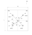
- FIG. 7 is a diagram for explaining an example of the installation range of sensors in the target space 80. It is assumed that one constant sensor S1 and six teacher data acquisition sensors S2 (S2a to S2f) are arranged in the target space 80. As shown in FIG. 7, the target space 80 includes regions 80a to 80d.
- the air conditioner A1 is arranged in a region 80a of the target space 80.
- Air conditioner A2 is arranged in region 80b of target space 80.
- Air conditioner A3 is arranged in region 80c of target space 80.
- the air conditioner A4 is arranged in a region 80d of the target space 80.
- the constant sensor S1 is placed at a placement candidate 31 in the target space 80, which is an intermediate position between the air conditioners A1 to A4.
- the teacher data acquisition sensor S2a is arranged at a placement candidate 32a near the air conditioner A1.
- the teacher data acquisition sensor S2b is placed in the placement candidate 32b near the air conditioner A2.
- the teacher data acquisition sensor S2c is placed in the placement candidate 32c near the air conditioner A3.
- the teacher data acquisition sensor S2d is placed in the placement candidate 32d near the air conditioner A4.
- the teacher data acquisition sensor S2e is placed at a placement candidate 32e that is not exposed to the airflow of the air conditioners A1 to A4.
- the teacher data acquisition sensor S2f is placed at a placement candidate 32f that is not exposed to the airflow of the air conditioners A1 to A4.
- a sensor placement determining device 10 is a sensor placement determining device 10 that determines the placement of sensors that measure the temperature within a target space 80, and includes an acquisition unit 20 and a determining unit 30.
- the acquisition unit 20 acquires air conditioner information 21 and spatial information 22.
- the air conditioner information 21 is information that associates the air conditioner A that affects the temperature with the effect of the distance from the air conditioner A on the temperature.
- the spatial information 22 is information regarding the arrangement of the air conditioner A within the target space 80.
- the determining unit 30 determines a placement candidate 31 for the constant sensor S1 and a placement candidate 32 for the teacher data acquisition sensor S2 in the target space 80 based on the air conditioner information 21 and the space information 22.
- the location where the airflow from the air conditioner reaches or does not reach the location at different heights within the air-conditioned space, the location where the influence of disturbance is strong or weak, the indoor unit of multiple refrigerant systems, etc.
- the aspect of temperature change differs depending on the location within the air-conditioned space, such as the location where it is affected.
- Conventionally, when controlling air conditioners using sensors installed in a space local values are obtained and reflected in air conditioning control. If a sensor is installed in a location with a singularity, such as a location with strong solar radiation, it may not be possible to create the desired environment.
- the position of the environmental sensor in the space is important not only for controlling the air conditioner, but also for obtaining the parameter distribution in the space for the purpose of visualizing the parameter distribution in the air conditioned space.
- the parameters in the air-conditioned space include, for example, temperature and humidity, CO 2 , airflow, and comfort level (PMV: predicted average thermal sensation report).
- a sensor that is always installed in space and a teacher data acquisition sensor that is collected after the teacher data is acquired are required. Permanent sensors are required at non-singularity locations. Sensors for acquiring teacher data must be installed at predetermined intervals in space, including singular points.
- this sensor placement determination device 10 by determining the placement candidates 31 of the constant sensor S1 and the placement candidates 32 of the teacher data acquisition sensor S2 in consideration of the influence on the temperature by the air conditioner A in the target space 80, The temperature within the target space 80 can be predicted with high accuracy.
- this sensor placement determination device 10 can determine the placement candidates 31 of the constant sensor S1 and the placement candidates 32 of the teacher data acquisition sensor S2 that achieve the target accuracy of temperature prediction, thereby achieving the accuracy of air conditioning control. It is possible to improve the accuracy of temperature distribution prediction. In addition, with this sensor placement determination device 10, it is possible to reduce the number of man-hours required to consider the installation positions of the constant sensor S1 and the teacher data acquisition sensor S2. The constant sensor S1 and the teacher data acquisition sensor S2 can be installed at the same position. In addition, in this sensor placement determination device 10, by acquiring air conditioner information 21 and spatial information 22, the installation positions of the sensor S1 and the teacher data acquisition sensor S2 can be constantly considered even if you are not in the actual space. be able to.
- the temperature at other positions where the teacher data acquisition sensor S2 is not placed can be determined.
- the cost of sensors can be reduced.
- the spatial information 22 includes information regarding the building design model 70.
- the factor that affects the temperature within the target space 80 is the air conditioner A.
- the air conditioner information 21 includes any of the model of the air conditioner A, the shape of the air conditioner (indoor unit) A, the capacity of the air conditioner A, the volume of conditioned air supplied by the air conditioner A, and the system information of the air conditioner A. It includes information regarding the influence on temperature depending on the distance from the air conditioner A, which is determined according to at least one of the combinations.
- the arrangement candidates 31 for the constant sensor S1 and the arrangement candidates 32 for the teacher data acquisition sensor S2 can be determined in consideration of the influence of the air conditioner A on the temperature in the target space 80. . Thereby, the arrangement candidates 31 for the constant sensor S1 and the arrangement candidates 32 for the teacher data acquisition sensor S2 can be appropriately determined in accordance with the air conditioner A installed in the target space 80.
- the air conditioner information 21 is determined according to at least one of the following: the direction of the conditioned air supplied by the air conditioner A, the blowing temperature, the blowing range, and the wind speed, or a combination thereof. , information regarding the influence on temperature according to the distance from the air conditioner A.
- the placement candidates 31 of the sensor S1 and the placement candidates 32 of the teacher data acquisition sensor S2 are always determined in consideration of the influence of the conditioned air supplied by the air conditioner A on the temperature in the target space 80. can be determined.
- the determining unit 30 calculates the floor area of the target space 80 from the spatial information 22, and constantly arranges sensors in the target space 80 according to the floor area of the target space 80. Determine the quantity 33 of S1.
- this sensor placement determining device 10 by determining the number 33 of sensors S1 to be installed at all times in consideration of the size of the target space 80, it is not necessary to arrange a large number of sensors, and costs can be reduced.
- the sensor placement determination method using the sensor placement determination device 10 is a sensor placement determination method for determining the placement of the sensor S that measures the temperature in the target space 80, and includes an acquisition step and a determination step. , is provided.
- air conditioner information 21 and spatial information 22 are acquired.
- the air conditioner information 21 is information that associates the air conditioner A with the influence of the distance from the air conditioner A.
- the spatial information 22 is information regarding the arrangement of the air conditioner A within the target space 80.
- a placement candidate 31 for the constant sensor S1 and a placement candidate 32 for the teacher data acquisition sensor S2 in the target space 80 are determined.
- the influence on the temperature by the air conditioner A in the target space 80 is considered, and the placement candidates 31 of the constant sensor S1 and the placement candidates of the teacher data acquisition sensor S2 are By determining 32, the temperature within the target space 80 can be predicted with high accuracy.
- the factor that influences the temperature in the target space 82 may be the ventilation device B (see FIG. 8). Furthermore, in the sensor placement determining device 10 shown in FIG. 1, the factors that influence the temperature within the target space 82 may be the air conditioner A and the ventilation device B.
- the ventilation system information includes the model of ventilation system B, the shape of ventilation system B, the ventilation volume of ventilation system B, the volume of air supplied by ventilation system B, the presence or absence of a total heat exchanger, the heat exchange efficiency of the total heat exchanger, and It includes information regarding the influence on temperature depending on the distance from the ventilation device B, which is determined depending on at least one of the presence or absence of a temperature adjustment function of the ventilation device B and a combination thereof.
- the distance from the ventilation device B When the distance from the ventilation device B is small, the influence of the ventilation device B on the temperature in the target space 82 becomes large, and the temperature change in the target space 82 due to the ventilation device B becomes large. For example, when the distance from the ventilation device B is about 3 m or less, the influence of the ventilation device B on the temperature in the target space 82 becomes large, but the distance from the ventilation device B is not limited to this.
- the types of ventilation equipment B include ventilation fans, total heat exchangers, humidity control outside air processing machines, etc.
- the shape of the ventilation device B includes a propeller fan, a sirocco fan, and the like.
- the ventilation amount of the ventilation device B When the ventilation amount of the ventilation device B is large, the influence of the ventilation device B on the temperature in the target space 82 becomes large. For example, when the ventilation amount of the ventilation device B is about 300 m 3 /h or more, the influence of the ventilation device B on the temperature in the target space 82 becomes large, but the ventilation amount of the ventilation device B is not limited to this.
- the influence of the ventilation device B on the temperature within the target space 82 becomes large.
- the volume of air supplied by ventilation system B is approximately 300 m3/h or more, the influence of ventilation system B on the temperature within the target space 82 becomes large; It is not limited.
- the ventilation device B is a total heat exchanger, heat exchange is performed between indoor air and outdoor air, so the temperature of the air obtained from the outdoors that is supplied indoors approaches the indoor air temperature. Therefore, the influence of the ventilation device B on the temperature within the target space 82 is reduced. Moreover, when the heat exchange efficiency of the total heat exchanger is high, the influence of the ventilation device B on the temperature within the target space 82 becomes small.
- the degree of influence of the ventilation device B on the temperature in the target space 82 differs depending on the operation details of the temperature adjustment function of the ventilation device B.
- the ventilation device B having a temperature adjustment function is operated so as to bring the temperature of the supplied air close to the room temperature, the influence of the ventilation device B on the temperature in the target space 82 becomes small.
- the ventilation device B having a temperature adjustment function is operated to supply temperature-controlled air to the target space 82 in the same way as the air conditioner A, the ventilation device B has a The impact will be greater.
- the temperature in the target space of the ventilation device B can be determined by inputting the ventilation device information into the sensor placement determining device 10. It is possible to obtain the range of influence for
- the arrangement candidate 31 of the constant sensor S1 and the arrangement candidate 32 of the teacher data acquisition sensor S2 in the target space 82 are set. can be determined.
- the factor that affects the temperature within the target space 82 may be the fixture C (see FIG. 8).
- Fixtures are appliances and furniture that are used on a daily basis.
- the fixtures are, for example, partitions, shelves, etc.
- the acquisition unit 20 acquires the fixture information as the first information.
- the fixture information includes information about the influence on temperature depending on the distance from the fixture C, which is determined depending on the type of fixture C. For example, if the fixture C placed in the target space 82 is a partition, the airflow in the target space 82 changes near the partition, so the measured value of the sensor is likely to be affected by the partition.
- the influence of the fixture C on the temperature in the target space 82 becomes large, and the temperature change in the target space 82 due to the fixture C becomes large.
- fixture C is a partition and the distance from fixture C is about 0.1 m or less, the influence of fixture C on the temperature in the target space 82 will be large, but the distance from fixture C is limited to this. It's not a thing.
- the factor that affects the temperature within the target space 82 may be a fixture (heating element) that generates heat.
- fixtures that generate heat include a personal computer F (see FIG. 8), a printing machine, and the like.
- the fixture that generates heat is a desktop computer and the distance from the desktop computer that generates 100 W of heat is approximately 0.2 m or less, the influence of the desktop computer on the temperature in the target space 82 will be large.
- the influence of the fixture C on the temperature in the target space 82 can be taken into consideration to determine the arrangement candidate 31 of the constant sensor S1 and the arrangement candidate 32 of the teacher data acquisition sensor S2.
- the factor that influences the temperature within the target space 82 may be a window D (see FIG. 8) that the target space 82 has.
- the acquisition unit 20 acquires the window information as the first information.
- the window information is determined based on at least one of the size of the window D, the coefficient of heat transmission, the solar gain coefficient, and the presence or absence of a shield, and the influence on the temperature according to the distance from the window D. be.
- the influence of the window D on the temperature in the target space 82 becomes large, and the temperature change in the target space 82 due to the window D becomes large.
- the distance from the window D is about 1.0 m or less, the influence of the window D on the temperature of the target space 82 becomes large, but the distance from the window D is not limited to this.
- the heat transfer coefficient is a value that indicates the ease with which heat is transferred when heat transfer occurs through the window D.
- the heat transmission coefficient can be calculated using software. Moreover, the heat transmission coefficient can be measured using a heat flow sensor. When the temperature difference between the outside and inside of the window D of the target space 82 is large, the heat transfer coefficient becomes high.
- the solar radiation acquisition coefficient is the period-average ratio of ⁇ the amount of solar radiation that can actually be obtained inside the building'' to ⁇ the amount of solar radiation that can be obtained assuming that there is no shielding by the building.'' When the solar radiation acquisition coefficient is large, the amount of heat generated by solar radiation is large.
- the shielding object is a curtain, blind, shoji, etc., and blocks sunlight from the window D.
- the measured value of the sensor is less affected by the window D.
- the measured value of the sensor is likely to be affected near the window D.
- the influence of the window D on the temperature in the target space 82 can be taken into consideration to determine the arrangement candidate 31 of the constant sensor S1 and the arrangement candidate 32 of the teacher data acquisition sensor S2.
- the factor that influences the temperature within the target space 82 may be the door E (see FIG. 8) that the target space 82 has.
- the acquisition unit 20 acquires the door information as the first information.
- the door information is the influence on the temperature according to the distance from the door E, which is determined according to at least one of the size, heat insulation performance, and opening/closing frequency of the door E, and a combination thereof.
- the influence of the door E on the temperature in the target space 82 becomes large, and the temperature change in the target space 82 due to the door E becomes large.
- the distance from the door E is about 2 m or less, the influence of the door E on the temperature in the target space 82 becomes large, but the distance from the door E is not limited to this.
- the measured value of the sensor is likely to be affected near the door E.
- the heat insulation performance of the door E is high, the amount of heat entering and exiting between the indoor and outdoor areas is reduced, and the measured value of the sensor in the target space 82 is less affected by the outside temperature.
- the influence of the door E on the temperature in the target space 82 can be taken into consideration to determine the placement candidates 31 for the constant sensor S1 and the placement candidates 32 for the teacher data acquisition sensor S2.
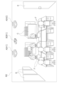
- FIG. 8 is a diagram for explaining factors that affect the environment within the target space 82.
- the target space 82 includes air conditioners A1 to A4 (A3 and A4 are not shown), ventilation devices B1 and B2 (B2 is not shown), fixtures C, and a window D. It has a door E and a computer F.
- the air conditioner A is a factor that affects the temperature within the target space 82, as described in this embodiment.
- the ventilation device B, the fixture C, the window D, and the door E are factors that affect the temperature within the target space 82, as described in Modifications 1A to 1D.
- the personal computer F is a heating element and is a factor that affects the temperature within the target space 82.
- the outer skin load G shown in FIG. 8 is a heat load that enters the room from the outside through the outer skin such as the ceiling, walls, and floor of the target space 82, and is a factor that affects the temperature inside the target space 82.
- the acquisition unit 20 acquires spatial information 22 (architectural drawings, piping drawings, CAD models, BIM models, etc.) of the target space 82 in which the constant sensor S1 and the teacher data acquisition sensor S2 are installed, and the installation position of the air conditioner A (indoor unit).
- spatial information 22 architectural drawings, piping drawings, CAD models, BIM models, etc.
- HVAC horizontal coordinates, height, etc.
- installation position of ventilation system B horizontal coordinates, height
- air conditioner information 21 model, indoor unit shape, capacity, air volume, system information
- ventilation system information model, shape, air volume
- presence or absence of a total heat exchanger heat exchange efficiency of the total heat exchanger, presence or absence of a temperature adjustment function
- location of fixtures C such as partitions
- location of heating elements such as computer F, location of people, heat flow through window D , the heat transmittance coefficient of the door E, the heat transmittance coefficient of the wall, the solar gain coefficient of the window D, etc.
- the determining unit 30 includes air conditioner information 21, air conditioner controller information, ventilation system information, spatial information 22 of the target space 82, installation position of air conditioner A, installation position of ventilation system B, position of fixtures C such as partitions, and information on people.
- air conditioner information 21 air conditioner controller information
- ventilation system information spatial information 22 of the target space 82
- installation position of air conditioner A installation position of ventilation system B
- position of fixtures C such as partitions
- information on people By using the location, heat transmittance coefficient of window D, heat transmittance coefficient of door E, heat transmittance coefficient of wall, solar gain coefficient, etc., "control the space most efficiently" and “correct real-time information of the entire space”. It is calculated where in the target space 82 the environmental information (temperature information) necessary for "obtaining" should be obtained.
- the numerical value 33 of the sensor S1 is always determined in consideration of the number of factors that affect the temperature within the target space 82, regardless of the number of factors that affect the temperature within the target space 82. First, the optimum value 33 of the sensor S1 can be determined at all times.
- sensing is required at the location where each air conditioner is air conditioned.
- the constant sensor parameter as an explanatory variable has an extra element in predicting the environmental sensor parameter for training data acquisition, or There may be a shortage of elements.
- the environmental sensor for acquiring training data needs to acquire training data at each position that is not a singular point and at each singular point.
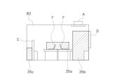
- FIGS. 9A and 9B are diagrams for explaining other examples of inappropriately placed positions of the sensor S1 at all times.
- the position where the sensor S1 is always inappropriately placed is near the singular point.
- a singular point is a point where the environment (temperature) locally differs from the surroundings.
- the specific points are, for example, a position 35a near the computer F which is a heat generating element, a position 35b where the influence of solar radiation from the window D is strong, and a position 35c in the shadow of the fixture C when viewed from the outlet of the air conditioner A. , near door E (see Figure 8), in a crowded area, etc.
- the distance within the target space 82 can be determined from the spatial information 22 regarding the arrangement of the heating element in the target space 82. Derive the singularity at .
- the peak heat load is roughly estimated from the size of window D, heat transmission coefficient, solar gain coefficient, presence or absence of shielding, and based on the estimated heat load, the influence distance on temperature is calculated. Derive the singularity. At this time, items that can be judged to have little effect on temperature, such as windows that are adjacent to another building and have little solar radiation, may be excluded from the singularity.
- the influence distance on the temperature is calculated and the singular point is derived.
- things that can be judged to have little effect on temperature such as closed doors, may be excluded from the singularity.
- the position where the sensor S1 is always inappropriately placed is a position where it cannot be installed.
- the non-installable position is a position 35d in the target space 82 where the sensor cannot be physically installed, such as in the air, or a floor surface 35e.
- areas such as areas where sensors cannot be physically installed, such as in the air, positions where it is inconvenient to constantly install sensors, such as on the floor, and positions far from living areas, such as on the ceiling, are acquired.
- the position (range) of improper placement of the sensor S1 at all times may include an installation prohibited range based on user input.
- the airflow reach range and singular point where temperature measurement is required are determined based on the position (range) of the improper placement of the sensor S1, and the airflow reach range and singular point other than the
- the installation position (range) of the teacher data acquisition sensor S2 is determined so that the teacher data acquisition sensor S2 spreads over the entire target space 82 at predetermined distance intervals.
- the distance interval of the teacher data acquisition sensor S2 is determined based on the target accuracy of temperature prediction.
- the teacher data acquisition sensor S2 it is also possible to specify the air, etc., which is excluded as the position (range) of inappropriate placement of the sensor S1 at all times. In that case, use something like a pole or tripod to An acquisition sensor S2 is arranged.
- the teacher data acquisition sensor S2 is installed in the air in the target space 82, the temperature distribution in the vertical direction within the target space 82 may be acquired.
- a position that is likely to be a singular point in the target spaces 80, 82 is estimated from the spatial information 22 acquired by the acquisition unit 20, and is always excluded from candidates for placement of the sensor S1. Thereby, it is possible to appropriately determine the placement candidate 31 for the permanent sensor S1 in consideration of the inappropriately placed position of the permanent sensor S1.
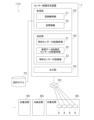
- FIG. 10 shows a functional block diagram of the air conditioning control system 110 of modification 1G.
- the air conditioning control system 110 includes an air conditioner A and a sensor placement determining device 11, as shown in FIG.
- the sensor placement determination device 11 is similar to the sensor placement determination device 10 of the air conditioning control system 100 of the present embodiment shown in FIG. 1 in that it includes an acquisition unit 20 and a determination unit 30. In the air conditioning control system 120 according to modification 1G, the sensor placement determining device 11 differs from the sensor placement determining device 10 shown in FIG. 1 in that it further includes an output unit 40.
- the output unit 40 outputs a placement candidate 31 for the constant sensor S1 in the target space 80 and a placement candidate 32 for the teacher data acquisition sensor S2 in the target space 80, determined by the determination unit 30.
- the output unit 40 distinguishes among a plurality of sensors with different purposes and outputs candidates for sensor placement within the target space 80.
- the output unit 40 distinguishes between the constant sensor S1 and the teacher data acquisition sensor S2, and selects the placement candidate 31 of the constant sensor S1 in the target space 80 and the teacher data acquisition sensor in the target space 80.
- the arrangement candidate 32 of S2 is output.
- the target space may be, for example, a target space 82 that includes an air conditioner A, a ventilation device B, and the like.
- FIG. 11 shows an example of the installation range of the constant sensor S1 and the teacher data acquisition sensor S2 in the target space 82 shown in FIG. 8.
- the installation candidate 31 for the constant sensor S1 is located away from the air conditioners A1 to A4, ventilation devices B1 and B2, fixtures C, window D, door E, and computer F (not shown). .
- the constant sensor S1 is placed, for example, at a height of 0.7 to 0.8 m, which is the height from the floor to the desk top.
- the placement candidate 32A of the teacher data acquisition sensor S2 is located near the air outlet of the ventilation device B1. Further, the placement candidate 32B for the teacher data acquisition sensor S2 is located near the fixture C. Further, the placement candidate 32C for the teacher data acquisition sensor S2 is located near the air conditioner A1 and near the window D. The placement candidate 32D for the teacher data acquisition sensor S2 is located near the air conditioner A1. Further, the placement candidate 32E for the teacher data acquisition sensor S2 is located near the air conditioner A2. Further, the placement candidate 32F of the teacher data acquisition sensor S2 is located near the air conditioner A3. Further, the placement candidate 32G for the teacher data acquisition sensor S2 is located near the air conditioner A4.
- the placement candidate 32H of the teacher data acquisition sensor S2 is located away from the air outlet of the ventilation device B2. Further, the placement candidate 32I of the teacher data acquisition sensor S2 is located away from the air outlet of the ventilation device B2.
- the teacher data acquisition sensor S2 is placed, for example, at a height of 0.7 to 0.8 m, which is the height from the floor to the desk top.
- the influence range of the factor that affects the environment in the space can be calculated, and the influence range of the factor can be calculated.
- the approximate installation positions of the constant sensor S1 and the teacher data acquisition sensor S2, estimated based on the above, are displayed on the design drawing or CAD model in an application for an air conditioning controller, a computer, a tablet, or other device. Thereby, it is possible to encourage the installation of sensors at appropriate positions in order to correctly acquire the environment of the entire space or to control the target space.
- the air conditioning may be controlled using the actually measured environment information (actually measured temperature information) acquired by the sensor S1 constantly installed at the position calculated by the sensor placement determining device 11 of modification 1G, or the predicted environment information (predicted temperature information ) may be used for control.
- the sensor placement determining device 11 may aim to obtain environmental information (temperature information) of the target spaces 80 and 82 by actually measuring or predicting.
- the optimal installation positions of the constant sensor S1 and the teacher data acquisition sensor S2 for the target spaces 80 and 82 are automatically selected and shown to the service engineer.
- the output unit 40 can constantly present the recommended installation positions (ranges) of the sensor S1 and the teacher data acquisition sensor S2 on the CAD model of the building, BIM model, architectural drawing, text, etc. on the application. can.
- the recommended installation position (range) of the constant sensor S1 and the teacher data acquisition sensor S2 can be visually understood using a CAD model, architectural drawing, or camera image of the indoor shape via an application such as an air conditioning controller or user terminal. It can be displayed on a user terminal, etc. after being displayed in a form that is superimposed on a file or in a text form.
- the position (range) where the permanent sensor S1 is inappropriately placed may be presented as the prohibited range for the permanent sensor S1.
- the output unit 40 outputs the placement candidates 31 of the constant sensor S1 in the target spaces 80 and 82 determined by the determining unit 30 and the teacher data acquisition sensors in the target spaces 80 and 82.
- the output unit 40 outputs the placement candidates 31 of the constant sensor S1 in the target spaces 80 and 82 determined by the determining unit 30 and the teacher data acquisition sensors in the target spaces 80 and 82.
- the determining unit 30 determines a position within the target space 80 that is affected by the distance from a factor that affects the temperature within the target space 80, or Even if a position that is not affected by the distance from a factor that affects the temperature of good.
- the output unit 40 outputs a placement candidate 31 for the always-on sensor S1 in the target space 80 and a placement candidate 32 for the teacher data acquisition sensor S2, or always The position of the inappropriate placement of the sensor S1 is output.
- the sensors with different purposes include a constant sensor S1 and a teacher data acquisition sensor S2.
- the constant sensor S1 is always installed within the target space 80.
- the teacher data acquisition sensor S2 is collected after acquiring data regarding the environment in the space.
- the output unit 40 can display, for example, the constant sensor S1 and the teacher data acquisition sensor S2 in a distinguishable manner on the application of the user terminal.
- the user may specify the position of the constant sensor S1, but if the user specifies the constant position of the sensor S1, the recommended position of the constant sensor S1 and the specified position by the user are compared and displayed, and further, the position is set as a target. Indicate to the user that the accuracy of temperature prediction will decrease.
- the output unit 40 outputs a notification of the timing at which the teacher data acquisition sensor S2 is collected from the target space 80, or a notification of the timing at which data acquisition by the teacher data acquisition sensor S2 ends.
- the target space may be, for example, a target space 82 that includes an air conditioner A, a ventilation system B, and the like.
- the sensor placement determination device 11 of the modification 1H by constantly acquiring the inappropriate placement position of the sensor S1, the placement candidate 31 of the sensor S1 and the placement of the teacher data acquisition sensor S2 are always determined in consideration of the inappropriate placement position. Candidates 32 can be determined. Furthermore, the sensor placement determining device 11 of Modification 1H can acquire the timing of collecting the teacher data acquisition sensor S2 and the timing of the end of data acquisition by the teacher data acquisition sensor S2.
- a sensor for constant observation of singular points may be installed at singular points that have a particularly strong impact on the environment.
- the target space may be, for example, a target space 82 that includes an air conditioner A, a ventilation system B, and the like.
- modification 1I by always determining the numerical value 33 of the sensor S1 in consideration of the size of the target space 80, it is possible to reduce costs without disposing a large number of sensors.
- the determining unit 30 may determine the number 33 of the constant sensors S1 to be arranged in the target space depending on the number of refrigerant systems.
- the air conditioner information (first information) 21 further includes information regarding the influence on temperature depending on the distance from the air conditioner A, which is determined depending on the quantity of refrigerant systems.
- the determining unit 30 may determine the number 33 of the constant sensors S1 to be arranged in the target space according to the number of air conditioners A. Furthermore, the air conditioner information 21 may further include information regarding the influence on temperature depending on the distance from the air conditioner A, which is determined depending on the quantity of the air conditioners A.
- FIG. 12 is a diagram for explaining the number of constantly installed sensors S1 in the target space 84 where the building multi-air conditioner is installed.
- the area where the same refrigerant piping system is installed is defined as one area, and one sensor is always installed in one area.
- the air conditioners A1 to A4 have the same refrigerant piping system and are installed in the first area 84a of the target space 84.
- the determining unit 30 determines that the number of constant sensors S1 installed in the first area 84a of the target space 84 is "1".
- the air conditioners A5 to A8 have the same refrigerant piping system and are installed in the second area 84b of the target space 84.
- the determining unit 30 determines that the number of constant sensors S1 disposed in the second area 84b of the target space 84 is "1".
- the number of constant sensors S1 may be determined by dividing the target space 84 into several areas and installing one constant sensor S1 in each area.
- FIG. 13 shows a functional block diagram of the air conditioning control system 120 of modification 1K.
- the air conditioning control system 120 includes an air conditioner A and a sensor placement determining device 12, as shown in FIG.
- the sensor placement determination device 12 of modification 1K includes an analysis section 50 and a determination section 300.
- the analysis unit 50 performs a thermal air flow analysis of the target space 80 regarding the influence within the target space 80 of factors that affect the temperature within the target space 80.
- the determining unit 300 determines a placement candidate 310 for the constant sensor S1 and a placement candidate 320 for the teacher data acquisition sensor S2 in the target space 80 based on the result 51 of the thermal airflow analysis of the target space 80.
- the target space may be a target space 82 that includes an air conditioner A, a ventilation system B, etc., for example.
- an analytical model of the target space as spatial information and performing airflow analysis such as CFD, the influence range of the air conditioner A, ventilation system B, etc. on the temperature of the target space may be acquired.
- the placement candidates 310 of the constant sensor S1 and the placement candidates 320 of the teacher data acquisition sensor S2 are determined in consideration of the result 51 of the thermal air flow analysis of the target space 80. , the temperature in the target space 80 can be measured with high precision using the arrangement candidate 310 of the constantly arranged sensor S1 and the arrangement candidate 320 of the teacher data acquisition sensor S2.
- the optimal position and quantity of the constant sensor S1 and the teacher data acquisition sensor S2 may be selected for the existing space, or the optimal position and quantity for the space at the design stage may be selected. It may also be used as a simulation of the placement positions of the constant sensor S1 and the teacher data acquisition sensor S2.
- Air conditioner information 100, 110, 120 Air conditioning control system 10, 11, 12 Sensor placement determining device 20 Acquisition unit 21 Air conditioner information (first information) 22 Spatial information (secondary information) 30, 300 Determining unit 31, 310 Continuous sensor placement candidate 32 (32a to 32d, 32A to 32I), 320 Teacher data acquisition sensor placement candidate 33 Number of continuous sensors installed 40 Output unit 50 Analysis unit 51 Hot air flow in space Analysis result A (A1 to A8) Air conditioner B (B1, B2) Ventilator S1 Constant sensor S2 Sensor for teacher data acquisition
Landscapes
- Engineering & Computer Science (AREA)
- Chemical & Material Sciences (AREA)
- Combustion & Propulsion (AREA)
- General Engineering & Computer Science (AREA)
- Mechanical Engineering (AREA)
- Life Sciences & Earth Sciences (AREA)
- Health & Medical Sciences (AREA)
- Physics & Mathematics (AREA)
- General Physics & Mathematics (AREA)
- Analytical Chemistry (AREA)
- Food Science & Technology (AREA)
- Medicinal Chemistry (AREA)
- Biochemistry (AREA)
- General Health & Medical Sciences (AREA)
- Immunology (AREA)
- Pathology (AREA)
- Automation & Control Theory (AREA)
- Air Conditioning Control Device (AREA)
Priority Applications (3)
| Application Number | Priority Date | Filing Date | Title |
|---|---|---|---|
| EP23780377.0A EP4502487A4 (de) | 2022-03-31 | 2023-03-27 | Sensorplatzierungsbestimmungsvorrichtung und sensorplatzierungsbestimmungsverfahren |
| CN202380032007.9A CN119137426A (zh) | 2022-03-31 | 2023-03-27 | 传感器配置决定装置以及传感器配置决定方法 |
| US18/890,530 US20250012466A1 (en) | 2022-03-31 | 2024-09-19 | Sensor arrangement determination device and sensor arrangement determination method |
Applications Claiming Priority (2)
| Application Number | Priority Date | Filing Date | Title |
|---|---|---|---|
| JP2022-061076 | 2022-03-31 | ||
| JP2022061076A JP7773427B2 (ja) | 2022-03-31 | 2022-03-31 | センサー配置決定装置およびセンサー配置決定方法 |
Related Child Applications (1)
| Application Number | Title | Priority Date | Filing Date |
|---|---|---|---|
| US18/890,530 Continuation US20250012466A1 (en) | 2022-03-31 | 2024-09-19 | Sensor arrangement determination device and sensor arrangement determination method |
Publications (1)
| Publication Number | Publication Date |
|---|---|
| WO2023190367A1 true WO2023190367A1 (ja) | 2023-10-05 |
Family
ID=88202293
Family Applications (1)
| Application Number | Title | Priority Date | Filing Date |
|---|---|---|---|
| PCT/JP2023/012255 Ceased WO2023190367A1 (ja) | 2022-03-31 | 2023-03-27 | センサー配置決定装置およびセンサー配置決定方法 |
Country Status (5)
| Country | Link |
|---|---|
| US (1) | US20250012466A1 (de) |
| EP (1) | EP4502487A4 (de) |
| JP (1) | JP7773427B2 (de) |
| CN (1) | CN119137426A (de) |
| WO (1) | WO2023190367A1 (de) |
Families Citing this family (1)
| Publication number | Priority date | Publication date | Assignee | Title |
|---|---|---|---|---|
| TWI825781B (zh) * | 2022-06-14 | 2023-12-11 | 研能科技股份有限公司 | 室內空污偵測清淨防止方法 |
Citations (5)
| Publication number | Priority date | Publication date | Assignee | Title |
|---|---|---|---|---|
| JP3548114B2 (ja) | 2000-12-26 | 2004-07-28 | 株式会社東芝 | 空調制御装置 |
| JP2014009498A (ja) * | 2012-06-29 | 2014-01-20 | Panasonic Corp | 断熱性能推定装置 |
| JP2017532688A (ja) * | 2015-03-06 | 2017-11-02 | 三菱電機株式会社 | 空調システム、並びに空調システムの動作を制御するためのシステム及び方法 |
| WO2021111617A1 (ja) * | 2019-12-06 | 2021-06-10 | 三菱電機株式会社 | 空調制御装置 |
| WO2021235139A1 (ja) * | 2020-05-18 | 2021-11-25 | パナソニックIpマネジメント株式会社 | 空調システム、建物及びプログラム |
-
2022
- 2022-03-31 JP JP2022061076A patent/JP7773427B2/ja active Active
-
2023
- 2023-03-27 CN CN202380032007.9A patent/CN119137426A/zh active Pending
- 2023-03-27 EP EP23780377.0A patent/EP4502487A4/de active Pending
- 2023-03-27 WO PCT/JP2023/012255 patent/WO2023190367A1/ja not_active Ceased
-
2024
- 2024-09-19 US US18/890,530 patent/US20250012466A1/en active Pending
Patent Citations (5)
| Publication number | Priority date | Publication date | Assignee | Title |
|---|---|---|---|---|
| JP3548114B2 (ja) | 2000-12-26 | 2004-07-28 | 株式会社東芝 | 空調制御装置 |
| JP2014009498A (ja) * | 2012-06-29 | 2014-01-20 | Panasonic Corp | 断熱性能推定装置 |
| JP2017532688A (ja) * | 2015-03-06 | 2017-11-02 | 三菱電機株式会社 | 空調システム、並びに空調システムの動作を制御するためのシステム及び方法 |
| WO2021111617A1 (ja) * | 2019-12-06 | 2021-06-10 | 三菱電機株式会社 | 空調制御装置 |
| WO2021235139A1 (ja) * | 2020-05-18 | 2021-11-25 | パナソニックIpマネジメント株式会社 | 空調システム、建物及びプログラム |
Non-Patent Citations (1)
| Title |
|---|
| See also references of EP4502487A4 |
Also Published As
| Publication number | Publication date |
|---|---|
| JP7773427B2 (ja) | 2025-11-19 |
| EP4502487A1 (de) | 2025-02-05 |
| CN119137426A (zh) | 2024-12-13 |
| EP4502487A4 (de) | 2025-07-30 |
| JP2023151464A (ja) | 2023-10-16 |
| US20250012466A1 (en) | 2025-01-09 |
Similar Documents
| Publication | Publication Date | Title |
|---|---|---|
| Bauman et al. | Testing and optimizing the performance of a floor-based task conditioning system | |
| US20170300599A1 (en) | System and method for calibrating multi-level building energy simulation | |
| Naboni et al. | Thermal comfort-CFD maps for architectural interior design | |
| Wu et al. | Optimizing demand-controlled ventilation with thermal comfort and CO2 concentrations using long short-term memory and genetic algorithm | |
| Abuimara et al. | Quantifying the impact of occupants’ spatial distributions on office buildings energy and comfort performance | |
| KR20230011815A (ko) | 복합 공조시스템의 실증 테스트를 위한 존별 구획, 존별 운전, 실시간 오염원의 모사가 가능한 시험장치 및 이에 의한 시험방법 | |
| Xin et al. | Efficiency evaluation of a floor standing air conditioner with different installation positions and air supply parameters applied to a large laboratory | |
| Liu et al. | Optimization of configurative parameters of stratum ventilated heating for a sleeping environment | |
| Abdollahzadeh et al. | Indoor environmental quality improvement of student dormitories in Tehran, Iran | |
| WO2023188096A1 (ja) | 空調制御装置および空調制御方法 | |
| WO2023190367A1 (ja) | センサー配置決定装置およびセンサー配置決定方法 | |
| Hurnik | Novel cylindrical induction controller and its application in VAV air conditioning system in an office building | |
| JP7628458B2 (ja) | 空調制御システム | |
| Kar et al. | Optimization of indoor airflow distribution in variable refrigerant flow air conditioning system: a review | |
| Varodompun et al. | HVAC ventilation strategies: the contribution for thermal comfort, energy efficiency, and indoor air quality | |
| Filipsson | Self-Regulating Active Chilled Beams | |
| US20230288089A1 (en) | Method and system for controlling building environmental control system | |
| Breesch et al. | Ventilative Cooling and Control Systems | |
| Yau et al. | Numerical simulation of a novel VRF-SV hybrid system performance in a large retail facility in the tropics | |
| Friedman | Too Hot| Too Cold: Diagnosing Occupant Complaints | |
| Yau et al. | Numerical simulation on supply air of high sidewall grille with retrofitted energy recovery ventilator system for thermal comfort in the tropics | |
| WO2022044079A1 (ja) | 空気調和システムおよび空気調和装置の制御方法 | |
| Poerschke | Measured Performance of a Varied Airflow Small-Diameter Duct System | |
| EP4317815B1 (de) | Informationsverarbeitungsvorrichtung und -programm | |
| JP7709013B2 (ja) | 風量調整装置の配置候補決定方法および空調空気供給システム |
Legal Events
| Date | Code | Title | Description |
|---|---|---|---|
| 121 | Ep: the epo has been informed by wipo that ep was designated in this application |
Ref document number: 23780377 Country of ref document: EP Kind code of ref document: A1 |
|
| WWE | Wipo information: entry into national phase |
Ref document number: 202380032007.9 Country of ref document: CN |
|
| WWE | Wipo information: entry into national phase |
Ref document number: 2023780377 Country of ref document: EP |
|
| ENP | Entry into the national phase |
Ref document number: 2023780377 Country of ref document: EP Effective date: 20241031 |
|
| NENP | Non-entry into the national phase |
Ref country code: DE |