WO2023190825A1 - 密封装置 - Google Patents
密封装置 Download PDFInfo
- Publication number
- WO2023190825A1 WO2023190825A1 PCT/JP2023/013081 JP2023013081W WO2023190825A1 WO 2023190825 A1 WO2023190825 A1 WO 2023190825A1 JP 2023013081 W JP2023013081 W JP 2023013081W WO 2023190825 A1 WO2023190825 A1 WO 2023190825A1
- Authority
- WO
- WIPO (PCT)
- Prior art keywords
- sealing device
- seal
- natural rubber
- main body
- jis
- Prior art date
- Legal status (The legal status is an assumption and is not a legal conclusion. Google has not performed a legal analysis and makes no representation as to the accuracy of the status listed.)
- Ceased
Links
Images


Classifications
-
- C—CHEMISTRY; METALLURGY
- C08—ORGANIC MACROMOLECULAR COMPOUNDS; THEIR PREPARATION OR CHEMICAL WORKING-UP; COMPOSITIONS BASED THEREON
- C08L—COMPOSITIONS OF MACROMOLECULAR COMPOUNDS
- C08L15/00—Compositions of rubber derivatives
-
- F—MECHANICAL ENGINEERING; LIGHTING; HEATING; WEAPONS; BLASTING
- F16—ENGINEERING ELEMENTS AND UNITS; GENERAL MEASURES FOR PRODUCING AND MAINTAINING EFFECTIVE FUNCTIONING OF MACHINES OR INSTALLATIONS; THERMAL INSULATION IN GENERAL
- F16J—PISTONS; CYLINDERS; SEALINGS
- F16J15/00—Sealings
- F16J15/02—Sealings between relatively-stationary surfaces
- F16J15/06—Sealings between relatively-stationary surfaces with solid packing compressed between sealing surfaces
- F16J15/10—Sealings between relatively-stationary surfaces with solid packing compressed between sealing surfaces with non-metallic packing
- F16J15/104—Sealings between relatively-stationary surfaces with solid packing compressed between sealing surfaces with non-metallic packing characterised by structure
-
- C—CHEMISTRY; METALLURGY
- C08—ORGANIC MACROMOLECULAR COMPOUNDS; THEIR PREPARATION OR CHEMICAL WORKING-UP; COMPOSITIONS BASED THEREON
- C08L—COMPOSITIONS OF MACROMOLECULAR COMPOUNDS
- C08L7/00—Compositions of natural rubber
-
- C—CHEMISTRY; METALLURGY
- C09—DYES; PAINTS; POLISHES; NATURAL RESINS; ADHESIVES; COMPOSITIONS NOT OTHERWISE PROVIDED FOR; APPLICATIONS OF MATERIALS NOT OTHERWISE PROVIDED FOR
- C09K—MATERIALS FOR MISCELLANEOUS APPLICATIONS, NOT PROVIDED FOR ELSEWHERE
- C09K3/00—Materials not provided for elsewhere
- C09K3/10—Materials in mouldable or extrudable form for sealing or packing joints or covers
-
- F—MECHANICAL ENGINEERING; LIGHTING; HEATING; WEAPONS; BLASTING
- F16—ENGINEERING ELEMENTS AND UNITS; GENERAL MEASURES FOR PRODUCING AND MAINTAINING EFFECTIVE FUNCTIONING OF MACHINES OR INSTALLATIONS; THERMAL INSULATION IN GENERAL
- F16J—PISTONS; CYLINDERS; SEALINGS
- F16J15/00—Sealings
- F16J15/002—Sealings comprising at least two sealings in succession
-
- F—MECHANICAL ENGINEERING; LIGHTING; HEATING; WEAPONS; BLASTING
- F16—ENGINEERING ELEMENTS AND UNITS; GENERAL MEASURES FOR PRODUCING AND MAINTAINING EFFECTIVE FUNCTIONING OF MACHINES OR INSTALLATIONS; THERMAL INSULATION IN GENERAL
- F16J—PISTONS; CYLINDERS; SEALINGS
- F16J15/00—Sealings
- F16J15/02—Sealings between relatively-stationary surfaces
- F16J15/021—Sealings between relatively-stationary surfaces with elastic packing
- F16J15/022—Sealings between relatively-stationary surfaces with elastic packing characterised by structure or material
-
- F—MECHANICAL ENGINEERING; LIGHTING; HEATING; WEAPONS; BLASTING
- F16—ENGINEERING ELEMENTS AND UNITS; GENERAL MEASURES FOR PRODUCING AND MAINTAINING EFFECTIVE FUNCTIONING OF MACHINES OR INSTALLATIONS; THERMAL INSULATION IN GENERAL
- F16J—PISTONS; CYLINDERS; SEALINGS
- F16J15/00—Sealings
- F16J15/02—Sealings between relatively-stationary surfaces
- F16J15/06—Sealings between relatively-stationary surfaces with solid packing compressed between sealing surfaces
- F16J15/10—Sealings between relatively-stationary surfaces with solid packing compressed between sealing surfaces with non-metallic packing
- F16J15/102—Sealings between relatively-stationary surfaces with solid packing compressed between sealing surfaces with non-metallic packing characterised by material
-
- F—MECHANICAL ENGINEERING; LIGHTING; HEATING; WEAPONS; BLASTING
- F16—ENGINEERING ELEMENTS AND UNITS; GENERAL MEASURES FOR PRODUCING AND MAINTAINING EFFECTIVE FUNCTIONING OF MACHINES OR INSTALLATIONS; THERMAL INSULATION IN GENERAL
- F16J—PISTONS; CYLINDERS; SEALINGS
- F16J15/00—Sealings
- F16J15/02—Sealings between relatively-stationary surfaces
- F16J15/06—Sealings between relatively-stationary surfaces with solid packing compressed between sealing surfaces
- F16J15/10—Sealings between relatively-stationary surfaces with solid packing compressed between sealing surfaces with non-metallic packing
- F16J15/12—Sealings between relatively-stationary surfaces with solid packing compressed between sealing surfaces with non-metallic packing with metal reinforcement or covering
- F16J15/121—Sealings between relatively-stationary surfaces with solid packing compressed between sealing surfaces with non-metallic packing with metal reinforcement or covering with metal reinforcement
- F16J15/122—Sealings between relatively-stationary surfaces with solid packing compressed between sealing surfaces with non-metallic packing with metal reinforcement or covering with metal reinforcement generally parallel to the surfaces
-
- F—MECHANICAL ENGINEERING; LIGHTING; HEATING; WEAPONS; BLASTING
- F16—ENGINEERING ELEMENTS AND UNITS; GENERAL MEASURES FOR PRODUCING AND MAINTAINING EFFECTIVE FUNCTIONING OF MACHINES OR INSTALLATIONS; THERMAL INSULATION IN GENERAL
- F16J—PISTONS; CYLINDERS; SEALINGS
- F16J15/00—Sealings
- F16J15/16—Sealings between relatively-moving surfaces
- F16J15/166—Sealings between relatively-moving surfaces with means to prevent the extrusion of the packing
-
- C—CHEMISTRY; METALLURGY
- C08—ORGANIC MACROMOLECULAR COMPOUNDS; THEIR PREPARATION OR CHEMICAL WORKING-UP; COMPOSITIONS BASED THEREON
- C08L—COMPOSITIONS OF MACROMOLECULAR COMPOUNDS
- C08L2312/00—Crosslinking
-
- C—CHEMISTRY; METALLURGY
- C09—DYES; PAINTS; POLISHES; NATURAL RESINS; ADHESIVES; COMPOSITIONS NOT OTHERWISE PROVIDED FOR; APPLICATIONS OF MATERIALS NOT OTHERWISE PROVIDED FOR
- C09K—MATERIALS FOR MISCELLANEOUS APPLICATIONS, NOT PROVIDED FOR ELSEWHERE
- C09K2200/00—Chemical nature of materials in mouldable or extrudable form for sealing or packing joints or covers
- C09K2200/02—Inorganic compounds
- C09K2200/0204—Elements
- C09K2200/0208—Carbon
-
- C—CHEMISTRY; METALLURGY
- C09—DYES; PAINTS; POLISHES; NATURAL RESINS; ADHESIVES; COMPOSITIONS NOT OTHERWISE PROVIDED FOR; APPLICATIONS OF MATERIALS NOT OTHERWISE PROVIDED FOR
- C09K—MATERIALS FOR MISCELLANEOUS APPLICATIONS, NOT PROVIDED FOR ELSEWHERE
- C09K2200/00—Chemical nature of materials in mouldable or extrudable form for sealing or packing joints or covers
- C09K2200/02—Inorganic compounds
- C09K2200/0243—Silica-rich compounds, e.g. silicates, cement, glass
- C09K2200/0247—Silica
-
- C—CHEMISTRY; METALLURGY
- C09—DYES; PAINTS; POLISHES; NATURAL RESINS; ADHESIVES; COMPOSITIONS NOT OTHERWISE PROVIDED FOR; APPLICATIONS OF MATERIALS NOT OTHERWISE PROVIDED FOR
- C09K—MATERIALS FOR MISCELLANEOUS APPLICATIONS, NOT PROVIDED FOR ELSEWHERE
- C09K2200/00—Chemical nature of materials in mouldable or extrudable form for sealing or packing joints or covers
- C09K2200/06—Macromolecular organic compounds, e.g. prepolymers
- C09K2200/0607—Rubber or rubber derivatives
-
- H—ELECTRICITY
- H01—ELECTRIC ELEMENTS
- H01M—PROCESSES OR MEANS, e.g. BATTERIES, FOR THE DIRECT CONVERSION OF CHEMICAL ENERGY INTO ELECTRICAL ENERGY
- H01M8/00—Fuel cells; Manufacture thereof
- H01M8/04—Auxiliary arrangements, e.g. for control of pressure or for circulation of fluids
- H01M8/04082—Arrangements for control of reactant parameters, e.g. pressure or concentration
- H01M8/04201—Reactant storage and supply, e.g. means for feeding, pipes
- H01M8/04216—Reactant storage and supply, e.g. means for feeding, pipes characterised by the choice for a specific material, e.g. carbon, hydride, absorbent
-
- Y—GENERAL TAGGING OF NEW TECHNOLOGICAL DEVELOPMENTS; GENERAL TAGGING OF CROSS-SECTIONAL TECHNOLOGIES SPANNING OVER SEVERAL SECTIONS OF THE IPC; TECHNICAL SUBJECTS COVERED BY FORMER USPC CROSS-REFERENCE ART COLLECTIONS [XRACs] AND DIGESTS
- Y02—TECHNOLOGIES OR APPLICATIONS FOR MITIGATION OR ADAPTATION AGAINST CLIMATE CHANGE
- Y02E—REDUCTION OF GREENHOUSE GAS [GHG] EMISSIONS, RELATED TO ENERGY GENERATION, TRANSMISSION OR DISTRIBUTION
- Y02E60/00—Enabling technologies; Technologies with a potential or indirect contribution to GHG emissions mitigation
- Y02E60/30—Hydrogen technology
- Y02E60/50—Fuel cells
Definitions
- the present invention relates to a sealing device.
- Natural rubber which is made from tree sap as a plant resource, has excellent mechanical strength and cold resistance, so it is useful for application to materials that require high sealing performance. Examples of applications in which the characteristics of natural rubber can be utilized include hydrogen sealing materials.
- a hydrogen society which is expected to be a means of decarbonization, does not emit carbon dioxide when using energy.
- Hydrogen stations and fuel cell vehicles have already been put into practical use to help realize a hydrogen society, but there is a need for sealing technology that can safely manage hydrogen without leaking at high pressure and over a wide temperature range. Therefore, the combination of hydrogen application and natural rubber can have a synergistic decarbonization effect, and can also be expected to suppress cracking under high pressure and improve elasticity loss (cold resistance) at low temperatures in seal products.
- diene rubbers such as natural rubber generally tend to undergo thermal deterioration.
- stress relaxation occurs due to oxidative decomposition, and permanent strain remains after compression is released.
- Such a phenomenon is fatal to seal products that seal fluids using rubber's resilience, so in order to apply natural rubber to hydrogen seal materials, it is necessary to improve its resistance to compression set in high-temperature air. There is.
- Patent Document 1 describes a sealing material for a high-pressure hydrogen container of a fuel cell vehicle that can withstand fluctuations in pressure or temperature, and natural rubber is exemplified as a type of applicable rubber.
- Patent Document 1 does not mention the improvement of the compression set resistance of natural rubber in high-temperature air, since it is aimed at sealing performance under a high-temperature hydrogen atmosphere rather than under a high-temperature air atmosphere.
- the exposure time to high-temperature hydrogen gas is relatively short at 1 hour, and furthermore, there is no description of formulation information for rubber materials that can achieve desired performance.
- the present invention provides a sealing device that exhibits high mechanical strength under high pressure and has excellent cold resistance at low temperatures and compression set resistance at high temperatures.
- a sealing device is a sealing device that is disposed between two members facing each other to seal a space between the two members, and includes a seal main body portion in contact with the space,
- the seal body has a tensile strength of 10 MPa or more as measured in accordance with the provisions of JIS K 6251:2017, and an elongation at break of 200% or more as measured in accordance with the provisions of JIS K 6251:2017.
- the temperature of TR10 in the low temperature elastic recovery test measured in accordance with the provisions of JIS K 6261-4:2017 is -40°C or less, and it is stated in the provisions of JIS B 2401-1:2012.
- the compression set of the G25 O-ring shape after 70 hours at 100°C is 40% or less, as measured in accordance with the regulations of JIS K 6262:2013.
- the seal body is annular.
- the seal main body is held by a backup ring.
- the seal body has a protruding cross-sectional shape.
- the seal main body is provided on a plate-shaped base material, and the base material is a metal or carbon plate.
- the base material and the seal main body are bonded together with an adhesive included in the seal main body.
- the seal main body is in contact with hydrogen gas.
- the seal body is in contact with liquid hydrogen.
- the sealing device is a sealing device for use in a hydrogen energy system.
- a sealing device is a sealing device that is disposed between two members facing each other to seal a space between the two members, and includes a seal main body portion in contact with the space.
- the seal main body portion is selected from (A) a natural rubber component selected from natural rubber and epoxy-modified natural rubber having a degree of epoxidation of 1% or more and less than 50%, and (B) carbon black and silica. (C) an organic peroxide-based crosslinking agent, and optionally (D) a silane coupling agent.
- the rubber composition contains epoxy-modified natural rubber having a degree of epoxidation of 1% or more and less than 50%, and when the filler is silica, the rubber composition further comprises silane coupling. containing agents).
- the rubber composition further contains (E) at least one additive selected from the group consisting of a crosslinking accelerator, an auxiliary agent, and an antiaging agent.
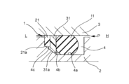
- FIG. 1 is a sectional view of a main part of a sealing device according to an embodiment of the present invention.
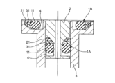
- FIG. 2 is a sectional view of a sealing device according to another embodiment of the sealing device shown in FIG.
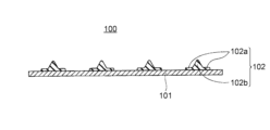
- FIG. 3 is a schematic diagram of a sealing device according to another embodiment of the present invention.
- FIG. 4 is a schematic cross-sectional view of the sealing device shown in FIG. 3.
- FIG. 5 is a schematic diagram showing the shape of a test piece prepared when measuring mechanical strength using test piece A obtained in Examples and Comparative Examples.
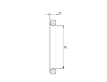
- FIG. 6 is a schematic diagram showing a cross section of a test piece shape prepared when measuring compression set using test piece B obtained in Examples and Comparative Examples.
- the sealing device according to the present embodiment is a sealing device that is disposed between two members facing each other to seal a space between the two members, and includes a seal main body portion in contact with the space.
- the sealing device according to this embodiment is preferably used in a hydrogen energy system, in which case the seal body is in contact with hydrogen gas or liquid hydrogen, and the sealing device is used as a hydrogen gas seal or liquid hydrogen seal. be done.
- FIG. 1 is an example of an embodiment of a sealing device including such a seal body.
- the sealing device 1 shown in FIG. 1 is installed in a mounting groove (installation part) 4 provided in one member 2 of two members 2 and 3 facing each other, and is brought into close contact with the other member 3. Seal the space between 2 and 3.
- the sealing device 1 includes a seal ring (rubber ring-shaped packing) 11 made of a rubber-like elastic body, a first backup ring (backup ring) 21 disposed on the low-pressure side L of the seal ring 11, and a seal ring 11 and a second backup ring.
- the second backup ring 31 is disposed between the first backup ring 21 and the second backup ring 31 .
- the two members 2 and 3 are, for example, high-pressure hydrogen piping for fuel cells that are connected to each other, and the seal housing portion of the other piping member 3 is disposed on the outer peripheral side of the seal housing portion of one piping member 2, and one
- the sealing device 1 is mounted in an annular mounting groove 4 provided on the outer peripheral surface of the seal housing portion of the piping member 2, and is in close contact with the inner peripheral surface of the seal housing portion of the other piping member 3.
- the sealing fluid is high pressure hydrogen gas that attempts to flow from the high pressure side H to the low pressure side L.
- a backup ring made of nylon (trade name) is used. Nylon is one of the resin materials that is difficult to pass through gas.
- a backup ring made of a softer material than the first backup ring 21, such as PTFE resin is used.
- an end ring with a cut at one point on the circumference is often used to facilitate installation, but if gas leakage is taken into account, an endless type without a cut is used. It is preferable that
- the seal ring 11 corresponds to a seal main body included in the sealing device according to the present invention.
- the seal ring 11 is formed into an annular shape, and is held by first and second backup rings 21 and 31.
- the material of the seal ring 11 is the same as the material forming the seal body described later, and the seal ring 11 exhibits the characteristics that the seal body described below has.
- the mounting groove 4 is basically formed as a space with a rectangular cross-section, but the high-pressure side mounting portion 4a of the groove bottom, into which the seal ring 11 is mounted, is formed into a flat cylindrical surface.
- the low pressure side mounting portion 4b for mounting the first and second backup rings 21, 31 which are continuous to the low pressure side L of the high pressure side mounting portion 4a has a spacing between the two members 2, 3 (radial spacing). ) is formed into a conical inclined surface shape so that it gradually narrows from the high pressure side H to the low pressure side L, that is, the groove depth of the mounting groove 4 becomes gradually shallower, and is formed as an inclined bottom surface 4c. .
- first and second backup rings 21 and 31 attached to the low-pressure side attachment portion 4b are each basically formed to have a rectangular cross section, but their inner peripheral surfaces correspond to the inclined bottom surface 4c. , are formed in the shape of an inclined surface forming a conical surface so that the inner diameter gradually increases from the high pressure side H to the low pressure side L, and are formed as inclined surfaces 21a and 31a.
- the seal ring 11 is pressed against the second backup ring 31 on the low pressure side. It is molded from a PTFE resin that is softer than the first backup ring 21. Therefore, it is possible to prevent the seal ring 11 from being repeatedly pressed against a hard material and being damaged when alternating pressure is generated.
- the second backup ring 31 is molded from PTFE resin, which is a soft material, it tends to protrude, but the first backup ring 21, which is molded from nylon, which is a hard material, prevents it from protruding. .
- the mounting groove 4 is provided with an inclined bottom surface 4c that gradually narrows the distance between the two members 2 and 3 from the high pressure side H to the low pressure side L, and both backup rings 21 and 31 are provided with an inclined bottom surface 4c, respectively.
- Corresponding inclined surfaces 21a and 31a are provided on the inner peripheral surface. Therefore, when the sealing fluid pressure acts on both backup rings 21, 31 through seal ring 11, both backup rings 21, 31 are compressed in a manner that they are pushed into a narrow space, and are tightly brought into close contact with the mating surfaces.
- the backup ring 21 is made of nylon, which is difficult to pass through gas. Therefore, from this point of view as well, it can be expected that leakage caused by high pressure hydrogen gas, which is a sealed fluid, permeating through the backup ring 21 can be effectively reduced. Furthermore, since the backup ring 21 has a radial width dimension smaller than that of the second backup ring 31, the transmission area is set to be small. Therefore, also from this point of view, it is possible to effectively seal the high-pressure hydrogen gas that is the sealed fluid.
- the sealing device 1 may be used not only for a cylindrical gap between two members, but also for a planar gap, that is, a gap between end faces.
- FIG. 2 is an example of an embodiment of such a sealing device.
- first and second backup rings 21 and 31 are arranged in the axial direction in order to seal the cylindrical gap between one piping member 2 and the other piping member 3.
- first and second backup rings 21 and 31 are arranged in the radial direction in order to seal the planar gap between one piping member 2 and the other piping member 3. .
- FIG. 3 is an example of a sealing device according to another embodiment of the present invention.
- the sealing device 100 shown in FIG. 3 is a seal component for a separator laminated on both sides of an electrolyte membrane/electrode assembly (hereinafter referred to as MEA) in a typical fuel cell, that is, a cell seal for a fuel cell.
- MEA electrolyte membrane/electrode assembly
- Such a cell seal for a fuel cell is disposed between two opposing members, a separator and an MEA, to seal the space between the separator and the MEA (not shown).
- fuel cell separators it is necessary to supply fuel cell fluid (fuel gas containing hydrogen, oxidant gas containing oxygen, etc.) to the MEA to prevent leakage to the outside, and the endless gasket is suitable for such fuel cells.
- the gasket serves to seal the fluid inside the space surrounded by the gasket.
- FIG. 4 shows a schematic cross section of the sealing device 100 taken along the line AA' in FIG. 3, and the gasket 102 is formed as four protrusions protruding from the surface of the base material 101.
- the gasket 102 has a base portion 102a adhered to the surface of the base material 101, and a seal lip portion 102b raised in the shape of a mountain from the base portion 102a. Note that there is a location (not shown) on line AA' in FIG. 3 where the material for molding the gasket 102 flows in and out during molding of the gasket 102.
- the base material 101 for example, a metal plate such as stainless steel or a thin plate such as a carbon plate is used.
- the base material 101 and the gasket 102 are bonded to each other via an adhesive layer or by an adhesive included in the gasket 102.
- the sealing device 100 may be an integrally molded cell seal in which an endless gasket 102 made of an elastic material and extending along the surface of the base material 101 is integrally molded on the surface of a plate-shaped base material 101.
- the base material 101 of such an integrally molded cell seal is a member included in the cell structure of a fuel cell that is integrally molded with the gasket 102, and includes a separator, an MEA, a gas diffusion layer (GDL), and the like.
- the gasket 102 corresponds to a seal main body included in the sealing device according to the present invention. As shown in FIG. 4, the gasket 102 has a protruding cross-sectional shape.
- the material of the gasket 102 is the same as the material forming the seal body described below, and the gasket 102 exhibits characteristics possessed by the seal body described below.
- the seal main body portion of the sealing device includes (A) a natural rubber component selected from natural rubber and epoxy-modified natural rubber having a degree of epoxidation of 1% or more and less than 50%, and (B) This is a vulcanized molded product of a rubber composition containing a filler selected from carbon black and silica, (C) an organic peroxide crosslinking agent, and optionally (D) a silane coupling agent.
- the filler is carbon black
- the rubber composition contains epoxy-modified natural rubber having a degree of epoxidation of 1% or more and less than 50%
- the filler is silica
- the rubber composition further contains a silane coupling agent.
- Natural rubber is thought to undergo an oxidative decomposition reaction starting from the diene structure (C ⁇ C bond) in a high-temperature air atmosphere. Therefore, in rubber compositions containing natural rubber components filled with carbon black, by using appropriately epoxidized natural rubber, compression set can be suppressed and the compression set resistance in high-temperature air can be improved. It can be improved. In addition, by adding a silane coupling agent to a rubber composition containing a silica-filled natural rubber component, even if the natural rubber is not epoxidized, it maintains excellent cold resistance and can be used in high-temperature air. Compression set resistance can be improved.
- the shape of the seal main body is not particularly limited, and can be made into any shape depending on the purpose.
- it may be a sheet-shaped sealing member with a square, rectangular, or disc-shaped cross-sectional shape, or an annular sealing member such as an O-ring or a square ring, and these annular parts may be formed in a part of the seal body. You can leave it there.
- Natural Rubber Component natural rubber that has not been chemically modified in any way, or natural rubber that has been modified with epoxy so that the diene portion is epoxidized to a degree of 1% or more and less than 50% is used.
- Natural rubber is a rubber refined from the sap (latex) of natural trees, and is a diene rubber that is different from synthetic rubber, which is manufactured by chemical synthesis using petroleum, naphtha, etc. as raw materials.
- the diene moiety of natural rubber can be epoxidized by reaction with formic acid and hydrogen peroxide.
- the epoxy-modified natural rubber has an epoxidation degree of 1% or more and less than 50%, preferably an epoxidation degree of 10% or more and 40% or less, and an epoxidation degree of 20% or more and 30% or less. It is more preferable to have the following.
- Natural rubber and epoxy-modified natural rubber may be used alone or in combination of two or more. By using such natural rubber, the mechanical properties of the seal body can be improved. Furthermore, the natural rubber and epoxy-modified natural rubber may be commercially available products. Commercial products of natural rubber and epoxy-modified natural rubber include, for example, natural rubber "RSS No. 1" (imported by Toyotsu Chemiplus), and natural rubber "ENR25” (imported by Sanyo Trading) with a degree of epoxidation of 25%. etc.
- the carbon black can be selected from known materials as appropriate, and includes, for example, super abrasion furnace (SAF) carbon black, intermediate super abrasion furnace (ISAF) carbon black, and high abrasion resistant carbon black.
- SAF super abrasion furnace
- IPF intermediate super abrasion furnace
- XCF Conductive Furnace
- FEF Fast Extruding Furnace
- GPF General Purpose Furnace
- HMF High Modulus Furnace
- SRF Semi-Reinforcing Furnace
- FT fine grain pyrolysis
- soft carbons such as fine thermal (MT) carbon black and medium thermal (MT) carbon black.
- examples of commercially available carbon black include "Vulcan (registered trademark) 3L" (HAF carbon) manufactured by Cabot Corporation.
- the content of carbon black is not particularly limited, but it is preferably 1 part by mass or more and 100 parts by mass or less, and 25 parts by mass or more and 75 parts by mass or less, based on 100 parts by mass of the natural rubber component. It is more preferable.
- One type of carbon black may be used alone, or two or more types may be used in combination.
- silica can be appropriately selected from known materials, it is preferable that it has good kneading workability.
- silica is dry process silica produced by thermal decomposition of halogenated silicic acid or organosilicon compounds, or by heating reduction of silica sand and air oxidation of vaporized SiO.
- Examples of commercially available silica products include "Ultrasil (registered trademark) 360" manufactured by Evonik Japan.
- the content of silica is not particularly limited, but it is preferably 1 part by mass or more and 100 parts by mass or less, and 25 parts by mass or more and 75 parts by mass or less, based on 100 parts by mass of the natural rubber component. is more preferable. Silica may be used alone or in combination of two or more.
- Organic peroxide crosslinking agent is used as a crosslinking agent to form peroxide crosslinks of the natural rubber component.
- organic peroxide-based crosslinking agent By using an organic peroxide-based crosslinking agent as a crosslinking agent, excellent compression set resistance is imparted to the seal main body.
- organic peroxide crosslinking agents include dicumyl peroxide, cumene hydroperoxide, p-methane hydroperoxide, 2,5-dimethylhexane-2,5-dihydroperoxide, and di-tert-butyl peroxide.
- organic peroxide crosslinking agent for example, "Percmil (registered trademark) D" manufactured by NOF Corporation can be used.
- the content of the organic peroxide crosslinking agent is preferably 0.1 parts by mass or more and 10 parts by mass or less, more preferably 1 part by mass or more and 5 parts by mass or less, based on 100 parts by mass of the natural rubber component. preferable.
- One type of organic peroxide crosslinking agent may be used alone, or two or more types may be used in combination.
- silane coupling agent silane coupling having a mercapto group is preferable, such as 3-mercaptopropyltrimethoxysilane, 3-mercaptopropyltriethoxysilane, 3-mercaptopropyldiethoxymethoxysilane, 3-mercaptopropyltripropoxy Silane, 3-mercaptopropyldipropoxymethoxysilane, 3-mercaptopropyltributoxysilane, 3-mercaptopropyldibutoxymethoxysilane, 3-mercaptopropylmethyldimethoxysilane, 3-mercaptopropyldimethylmethoxysilane, 3-mercaptopropyldibutoxymethoxysilane Ethoxysilane, 3-mercaptopropyldimethylethoxysilane, 3-mercaptopropylmethyl
- silane coupling agent for example, "KBM-803" manufactured by Shin-Etsu Silicone Co., Ltd. can be used.
- the content of the silane coupling agent is preferably 0.1 parts by mass or more and 10 parts by mass or less, and more preferably 1 part by mass or more and 5 parts by mass or less, based on 100 parts by mass of the natural rubber component.
- the silane coupling agents may be used alone or in combination of two or more.
- the rubber composition may further contain other compounding components in addition to the above-mentioned components, if necessary.
- other ingredients include various additives such as crosslinking accelerators, plasticizers, anti-aging agents, auxiliaries, lubricants, adhesives, lubricants, flame retardants, fungicides, and antistatic agents. These additives may be used alone or in combination of two or more. Further, the amount of these ingredients to be blended is not particularly limited as long as it does not impede the purpose or effect of the present invention, and the amount can be appropriately blended depending on the purpose of blending.
- the method for manufacturing the seal main body is not particularly limited, but includes, for example, the natural rubber component, filler, and organic peroxide crosslinking agent described above, and the silane blended as necessary.
- the mixture is kneaded using a kneading machine such as a single-screw extruder, twin-screw extruder, roll, Banbury mixer, kneader, or high-shear mixer.
- a kneading machine such as a single-screw extruder, twin-screw extruder, roll, Banbury mixer, kneader, or high-shear mixer.
- a rubber composition is produced by this process.
- kneading, mastication, preliminary kneading, etc. may be performed as necessary.
- a vulcanized molded product having the shape of the seal main body can be manufactured.
- Vulcanization molding of the rubber composition is generally carried out by pressure vulcanization at about 150 to 230° C. for about 0.5 to 30 minutes using an injection molding machine, a compression molding machine, or the like.
- secondary vulcanization may be performed as necessary to ensure that the inside of the vulcanized product is vulcanized.
- Secondary vulcanization can generally be carried out by oven heating, steam heating, hot air heating, etc. at about 150 to 250° C. for about 0.5 to 24 hours.
- the seal main body of the sealing device according to this embodiment was measured in accordance with the provisions of JIS K6251:2017 (Japanese Industrial Standard created by changing the technical content based on ISO 37 (2011 5th edition)).
- JIS K6251:2017 Japanese Industrial Standard created by changing the technical content based on ISO 37 (2011 5th edition)
- the elongation at cutting of the seal body was measured in accordance with the regulations of JIS K 6251:2017 (test piece shape: dumbbell No. 6 shape, speed: 500 mm/min, distance between gauge lines: 20 ⁇ 0.
- seal body has a tensile strength of 10 MPa or more and an elongation at break of 200% or more, it is possible to provide a sealing device including a seal body that exhibits high mechanical strength even under high pressure.
- the seal main body of the sealing device complies with the provisions of JIS K6261-4:2017 (Japanese Industrial Standard created by changing the technical content based on ISO 2921 (5th edition, 2011)).
- Temperature of TR10 in the low temperature elastic recovery test (TR test) measured in The temperature of TR10 in a low temperature elastic recovery test (TR test) measured under the following conditions is preferably -40°C or lower, and preferably -60°C or lower. Since the temperature at TR10 is ⁇ 40° C. or lower, it is possible to provide a sealing device including a seal main body portion that has excellent cold resistance in a low temperature range.
- JIS B 2401-1:2012 Japanese Industrial Standard created by changing the technical content based on ISO 3601-1 (2008 4th edition)
- JIS K 6262:2013 regulations ISO815-1 and ISO815-2 (both 2008 1st edition)
- Nihon Kogyo Co., Ltd. created the G25 O-ring shape described in the G25 O-ring shape by changing the technical content.
- the present invention relates to the following [1] to [7].
- the seal main body has a tensile strength of 10 MPa or more as measured in accordance with the provisions of JIS K 6251:2017, and an elongation at break of 200% or more as measured in accordance with the provisions of JIS K 6251:2017.
- the temperature of TR10 in the low temperature elastic recovery test measured in accordance with the provisions of JIS K 6261-4:2017 is -40°C or less, and the temperature is specified in the provisions of JIS B 2401-1:2012.
- the seal body has a protruding cross-sectional shape.
- the seal main body portion is provided on a plate-shaped base material, and the base material is a metal or carbon plate.
- the seal body is selected from (A) a natural rubber component selected from natural rubber and epoxy-modified natural rubber having a degree of epoxidation of 1% or more and less than 50%, and (B) carbon black and silica.
- the rubber composition contains epoxy-modified natural rubber having a degree of epoxidation of 1% or more and less than 50%, and the filler is silica, the rubber composition further contains a silane coupling agent. ).
- the rubber composition further contains (E) at least one additive selected from the group consisting of a crosslinking accelerator, an auxiliary agent, and an anti-aging agent.
- Example 1 100 parts by mass of natural rubber with a degree of epoxidation of 25% ("ENR25”, imported by Sanyo Trading Co., Ltd.) was put into a kneading extrusion device ("Laboplast Mill 30C150", manufactured by Toyo Seiki Co., Ltd.) and heated at 50°C for 15 minutes.
- filler A carbon black: trade name "Vulcan (registered trademark) 3L", manufactured by Cabot Japan
- crosslinking agent A dicumyl peroxide: trade name “Percumil (registered trademark)" D", manufactured by NOF Corporation
- auxiliary agent A zinc white: trade name "zinc oxide", manufactured by Seido Kagaku Kogyo Co., Ltd.
- auxiliary agent B stearic acid: trade name "DTST" '', manufactured by Miyoshi Oil Co., Ltd.
- anti-aging agent 2,2,4-trimethyl-1,2-dihydroquinoline polymer: trade name ⁇ Nocrac 224'', manufactured by Ouchi Shinko Kagaku Kogyo Co., Ltd.
- the obtained rubber dough was put into a roll kneading machine ("LABORTORY MILL", manufactured by Kansai Roll Co., Ltd.), and the rubber dough was passed through it five times with a roll gap of 1.5 to 2.5 mm, and then kneaded with a roll kneader of 1 mm.
- a rubber composition was prepared by passing the rubber composition 10 times.
- Example 2 Natural rubber (“RSS No. 1", Toyotsu Chemiplus imported product) was used instead of natural rubber with a degree of epoxidation of 25%, and filler B (silica: trade name “Ultrasil (registered trademark) 360") was used instead of filler A.
- Example 1 except that 1 part by mass of a silane coupling agent (mercapto group-containing silane coupling agent: trade name "KBM-803", manufactured by Shin-Etsu Silicone Co., Ltd.) was used.
- a rubber composition and test pieces A and B were prepared in the same manner, and the above measurements were performed. The results are shown in Table 1.
- Natural rubber (“RSS No. 1", Toyotsu Chemiplus imported product) was used instead of natural rubber with a degree of epoxidation of 25%, crosslinking agent B was replaced with crosslinking agent A (sulfur: trade name "Colloidal Sulfur A”, Tsurumi Chemical Co., Ltd.) (manufactured by Kogyo Co., Ltd.), and further crosslinking accelerator A (N-cyclohexyl-2-benzothiazolesulfenamide: trade name "Noxela (registered trademark) CZ-G", manufactured by Ouchi Shinko Kagaku Co., Ltd.).
- crosslinking agent A sulfur: trade name "Colloidal Sulfur A", Tsurumi Chemical Co., Ltd.
- further crosslinking accelerator A N-cyclohexyl-2-benzothiazolesulfenamide: trade name "Noxela (registered trademark) CZ-G", manufactured by Ouchi Shinko Kagaku Co., Ltd.
- crosslinking accelerator B tetramethylthiuram disulfide: trade name "Noxela (registered trademark) TT-P", manufactured by Ouchi Shinko Kagaku Co., Ltd.
- a rubber composition and test pieces A and B were prepared in the same manner as in Example 1, except that the crosslinking temperature was changed from 170°C to 150°C, and the above measurements were performed. The results are shown in Table 1.
- Rubber compositions and test pieces A and B were prepared in the same manner as in Example 1, except that natural rubber ("RSS No. 1", imported from Toyotsu Chemiplus) was used instead of natural rubber having a degree of epoxidation of 25%. was prepared and the above measurements were performed. The results are shown in Table 1.
- Example 4 A rubber composition and test pieces A and B were prepared in the same manner as in Example 2, except that no silane coupling agent was blended, and the above measurements were performed. The results are shown in Table 1.
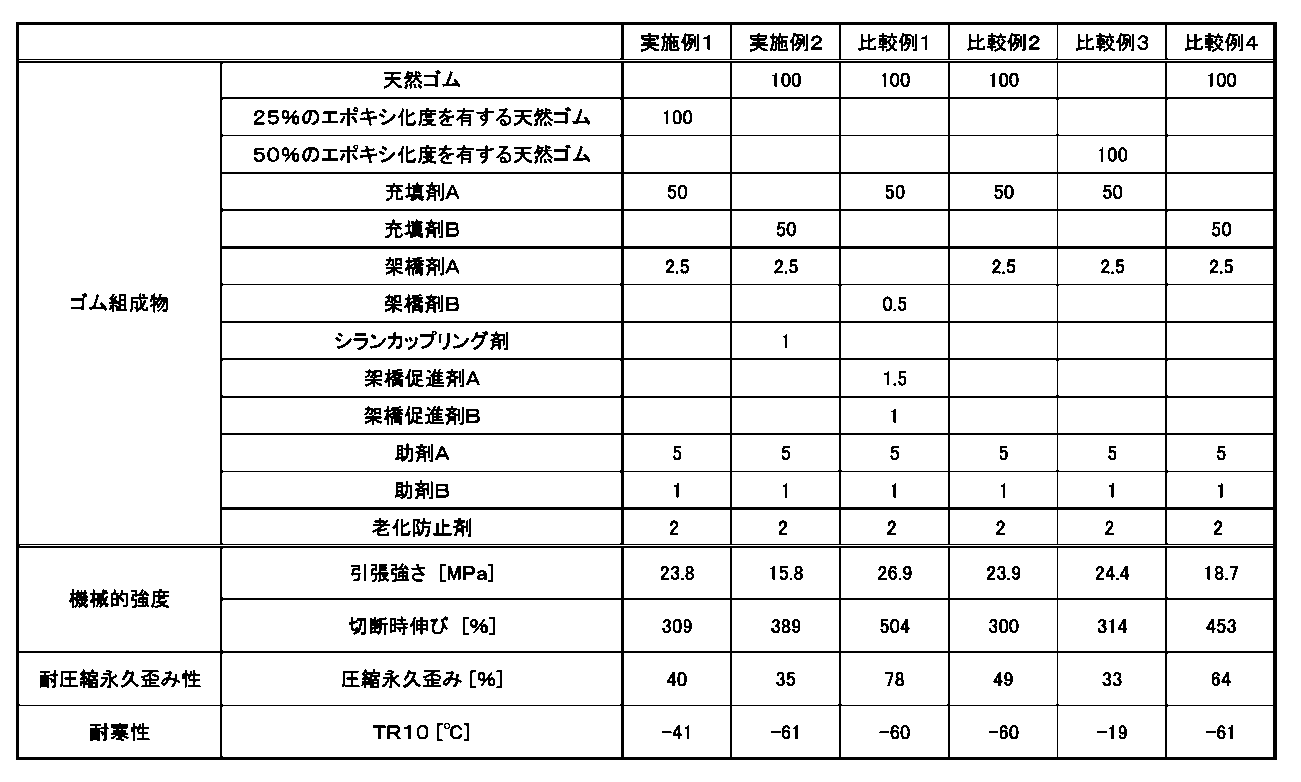
- Examples 1 and 2 had a tensile strength of 10 MPa or more and an elongation at break of 200% or more, and exhibited high mechanical strength even under high pressure. Furthermore, in Examples 1 and 2, the temperature of TR10 in the low-temperature elastic recovery test was -40°C or lower, and furthermore, the compression set after 70 hours at 100°C was 40% or lower. It had excellent cold resistance and compression set resistance at high temperatures.
- Comparative Example 1 in which a sulfur crosslinking agent was used as a crosslinking agent, the compression set was higher than 40%, and the compression set resistance was poor.
- Comparative Example 2 which used carbon black as a filler and unmodified natural rubber as a natural rubber component, had a compression set higher than 40% and was inferior in compression set resistance. Ta.
- Comparative Example 3 which used carbon black as a filler and natural rubber with a degree of epoxidation of 50% as a natural rubber component, the compression set was 40% or less, but the low temperature elastic recovery test The temperature of TR10 was higher than -40°C, and the cold resistance was poor.
- Comparative Example 4 in which silica was used as a filler but no silane coupling agent was used, the compression set was higher than 40% and the compression set resistance was poor.
- 1, 1A, 1B sealing device 2 one member (piping member), 3 other member (piping member), 4 mounting groove, 4a high pressure side mounting part, 4b low pressure side mounting part, 4c inclined bottom surface, 11 seal ring, 21 First backup ring (backup ring), 21a, 31a slope, 31 second backup ring, 100 sealing device, 101 base material, 101a ventilation hole, 102 gasket, 102a base part, 102b seal lip part
Landscapes
- Engineering & Computer Science (AREA)
- General Engineering & Computer Science (AREA)
- Chemical & Material Sciences (AREA)
- Mechanical Engineering (AREA)
- Organic Chemistry (AREA)
- Health & Medical Sciences (AREA)
- Chemical Kinetics & Catalysis (AREA)
- Medicinal Chemistry (AREA)
- Polymers & Plastics (AREA)
- Materials Engineering (AREA)
- Compositions Of Macromolecular Compounds (AREA)
- Gasket Seals (AREA)
- Sealing Material Composition (AREA)
Abstract
Description
本実施形態に係る密封装置は、互いに対向する二部材の間に配置されて、前記二部材の間の空間を密封する密封装置であって、当該空間と接するシール本体部を備えている。本実施形態に係る密封装置は、水素エネルギーシステムに使用されることが好ましく、その際、シール本体部は水素ガスまたは液体水素に接しており、密封装置は、水素ガスシールまたは液体水素シールとして使用される。
図1は、このようなシール本体部を備える密封装置の実施形態の一例である。図1に示される密封装置1は、互いに対向する二部材2,3のうちの一方の部材2に設けた装着溝(装着部)4に装着されて他方の部材3に密接し、もって二部材2,3間を密封する。密封装置1は、ゴム状弾性体よりなるシールリング(ゴム製リング状パッキン)11と、シールリング11の低圧側Lに配置される第一バックアップリング(バックアップリング)21と、シールリング11と第一バックアップリング21との間に配置される第二バックアップリング31とを有している。上記二部材2,3は例えば、互いに連結される燃料電池用高圧水素配管であって、一方の配管部材2におけるシールハウジング部の外周側に他方の配管部材3のシールハウジング部が配置され、一方の配管部材2のシールハウジング部の外周面に設けた環状の装着溝4に当該密封装置1が装着されて、他方の配管部材3のシールハウジング部の内周面に密接している。密封流体は、高圧側Hから低圧側Lへ流れようとする高圧水素ガスである。
図3は、本発明の他の実施形態に係る密封装置の一例である。図3に示される密封装置100は、一般的な燃料電池において電解質膜/電極集合体(以下、MEAと呼ぶ)の両側に積層されるセパレータ用のシール部品、すなわち燃料電池用セルシールである。このような燃料電池用セルシールは、互いに対向する二部材であるセパレータとMEAの間に配置されて、セパレータとMEAの間の空間を密封する(図示せず)。燃料電池のセパレータでは、外部に漏れないようにMEAに燃料電池用の流体(水素を含む燃料ガスや酸素を含む酸化剤ガス等)を供給する必要があり、無端形状のガスケットは、こうした燃料電池用の流体を、ガスケットで囲まれた空間内に封止(シール)する役割を果たす。
本実施形態に係る密封装置が有するシール本体部は、(A)天然ゴム及び1%以上50%未満のエポキシ化度を有するエポキシ変性された天然ゴムから選択される天然ゴム成分と、(B)カーボンブラック及びシリカから選択される充填剤と、(C)有機過酸化物系架橋剤と、任意に(D)シランカップリング剤とを含有するゴム組成物の加硫成型品である。但し、充填剤がカーボンブラックである場合、ゴム組成物は1%以上50%未満のエポキシ化度を有するエポキシ変性された天然ゴムを含有し、且つ、充填剤がシリカである場合、ゴム組成物はさらにシランカップリング剤を含有する。天然ゴムは、高温空気雰囲気下でジエン構造(C=C結合)を起点として酸化分解反応を起こすと考えられている。そのため、カーボンブラックを充填した天然ゴム成分を含むゴム組成物においては、適切にエポキシ化された天然ゴムを使用することにより、圧縮永久歪みが抑制され、高温空気中での耐圧縮永久歪み性を改善させることができる。また、シリカを充填した天然ゴム成分を含むゴム組成物にさらにシランカップリング剤を添加することにより、天然ゴムがエポキシ化されていなくとも、優れた耐寒性を維持しつつ、高温空気中での耐圧縮永久歪み性を改善させることができる。
天然ゴム成分は、何ら化学変性されていない天然ゴム、又は、ジエン部分が1%以上50%未満のエポキシ化度でエポキシ変性された天然ゴムが使用される。天然ゴムは、天然の樹の樹液(ラテックス)から精製されたゴムであり、石油やナフサなどを原料として化学合成されて製造される合成ゴムとは異なるジエン系ゴムである。天然ゴムのジエン部分は、ギ酸と過酸化水素水との反応によりエポキシ化させることができる。エポキシ変性された天然ゴムは、1%以上50%未満のエポキシ化度を有しており、10%以上40%以下のエポキシ化度を有することが好ましく、20%以上30%以下のエポキシ化度を有することがより好ましい。
ゴム組成物には、充填剤が配合されている。ゴム組成物中に充填剤が含まれることにより、得られる加硫物の機械強度、圧縮永久歪性を向上させることができる。充填剤として、補強材として一般的な、カーボンブラック及びシリカが用いられる。充填剤は、1種単独で使用してもよく、2種以上を併用してもよい。
有機過酸化物系架橋剤は、天然ゴム成分のパーオキサイド架橋を形成する架橋剤として使用される。架橋剤として有機過酸化物系架橋剤を使用することにより、シール本体部に優れた耐圧縮永久歪み性が付与される。有機過酸化物系架橋剤としては、例えば、ジクミルパーオキサイド、クメンヒドロパーオキサイド、p-メタンヒドロパーオキサイド、2,5-ジメチルヘキサン-2,5-ジヒドロパーオキサイド、ジ-tert-ブチルパーオキサイド、ベンゾイルパーオキシド、m-トルイルパーオキサイド、2,5-ジメチル-2,5-ビス(tert-ブチルパーオキシ)ヘキサン、2,5-ジメチル-2,5-ビス(tert-ブチルパーオキシ)-3-ヘキシン、1,3-ビス(tert-ブチルパーオキシイソプロピル)ベンゼン、2,5-ジメチル-2,5-ジ(ベンゾイルパーオキシ)ヘキサン、1,1,3,3-テトラメチルブチルパーオキシ-2-エチルヘキサノエート、tert-ブチルパーオキシベンゾエート、tert-ブチルパーオキシラウレート、ジ(tert-ブチルパーオキシ)アジペート、ジ(2-エトキシエチルパーオキシ)ジカルボナート、ビス(4-tert-ブチルシクロヘキシル)パーオキシジカルボナート等が挙げられる。これらの中でも、ジクミルパーオキサイドが好ましい。
ゴム組成物が充填剤としてシリカを含有する場合、ゴム組成物にさらにシランカップリング剤を配合する。シランカップリング剤としては、メルカプト基を有するシランカップリングが好ましく、例えば、3-メルカプトプロピルトリメトキシシラン、3-メルカプトプロピルトリエトキシシラン、3-メルカプトプロピルジエトキシメトキシシラン、3-メルカプトプロピルトリプロポキシシラン、3-メルカプトプロピルジプロポキシメトキシシラン、3-メルカプトプロピルトリブトキシシラン、3-メルカプトプロピルジブトキシメトキシシラン、3-メルカプトプロピルメチルジメトキシシラン、3-メルカプトプロピルジメチルメトキシシラン、3-メルカプトプロピルメチルジエトキシシラン、3-メルカプトプロピルジメチルエトキシシラン、3-メルカプトプロピルメチルジプロポキシシラン、3-メルカプトプロピルプロポキシジメチルシラン、3-メルカプトプロピルメチルジイソプロポキシシラン、3-メルカプトプロピルイソプロポキシジメチルシラン、3-メルカプトプロピルメチルジブトキシシラン、3-メルカプトプロピルジメチルブトキシシラン、2-メルカプトエチルトリメトキシシラン、2-メルカプトエチルトリエトキシシラン、メルカプトメチルトリメトキシシラン、メルカプトメチルトリエトキシシラン等が挙げられる。
ゴム組成物は、必要に応じて、上記の成分以外にさらに他の配合成分を含んでいてもよい。他の配合成分として、例えば、架橋促進剤、可塑剤、老化防止剤、助剤、滑剤、粘着剤、潤滑剤、難燃剤、防黴剤、帯電防止剤等の各種の添加剤が挙げられる。これらの添加剤は、1種単独で使用してもよく、2種以上を併用してもよい。また、これらの配合量は、本発明の目的や効果を阻害しない範囲であれば特に限定されず、配合目的に応じた量を適宜配合することができる。
シール本体部の製造方法は、特に限定されるものではないが、例えば、上記に記載される天然ゴム成分、充填剤及び有機過酸化物系架橋剤、さらには、必要に応じて配合されるシランカップリング剤、任意の各種添加剤を所定の割合で適宜配合した後、例えば、一軸押出機、二軸押出機、ロール、バンバリーミキサ、ニーダ、高剪断型ミキサなどの混練機を用いて混練することによりゴム組成物を製造する。尚、混練の前に、必要に応じて素練り、予備混練等を施してもよい。
本実施形態に係る密封装置が有するシール本体部において、JIS K6251:2017の規定(ISO37(2011年第5版)を基とし、技術内容を変更して作成した日本工業規格)に準拠して測定された引張強さ(試験片形状:ダンベル状6号形、速度:500mm/分、標線間距離:20±0.5mm、雰囲気:空気、試験温度:室温の条件で測定された引張強さ)が10MPa以上であり、15MPa以上であることが好ましい。また、シール本体部において、JIS K 6251:2017の規定に準拠して測定された切断時伸び(試験片形状:ダンベル状6号形、速度:500mm/分、標線間距離:20±0.5mm、雰囲気:空気、試験温度:室温の条件で測定された切断時伸び)が200%以上であり、300%以上であることが好ましい。シール本体部が、10MPa以上の引張強さ及び200%以上切断時伸びを有するため、高圧下でも高い機械的強度を示すシール本体部を備える密封装置を提供できる。
本実施形態に係る密封装置が有するシール本体部において、JIS K6261-4:2017の規定(ISO2921(2011年第5版)を基とし、技術内容を変更して作成した日本工業規格)に準拠して測定された低温弾性回復試験(TR試験)におけるTR10の温度(試験片形状:JIS K6261-4:2017の規定に記載のI字状、熱媒体:エタノール、試験温度:-70℃~23℃の条件で測定された低温弾性回復試験(TR試験)におけるTR10の温度)が、-40℃以下であり、-60℃以下であることが好ましい。TR10における温度が-40℃以下であるため、低温域で耐寒性に優れるシール本体部を備える密封装置を提供できる。
本実施形態に係る密封装置が有するシール本体部において、JIS B 2401-1:2012の規定(ISO3601-1(2008年第4版)を基とし、技術内容を変更して作成した日本工業規格)に記載されているG25 Oリングの形状にてJIS K 6262:2013の規定(ISO815-1及びISO815-2(いずれも2008年第1版)を基とし、技術内容を変更して作成した日本工業規格)に準拠して測定された100℃で70時間経過後の圧縮永久歪み(圧縮板:平滑ステンレス鋼板、試験片形状:JIS B 2401-1:2012の規定に記載されるG25 Oリング、スペーサ厚:2.30mm、圧縮率:25%、雰囲気:空気、試験温度:100℃、暴露時間:70時間、開放後の放置条件:室温にて30分間の条件で測定した圧縮永久歪み)が40%以下であり、35%以下であることが好ましい。このような条件下での圧縮永久歪みが40%以下であるため、高温域で耐圧縮永久歪み性に優れるシール本体部を備える密封装置を提供できる。
[1]
互いに対向する二部材の間に配置されて、前記二部材の間の空間を密封する密封装置であって、
前記空間と接するシール本体部を備え、
前記シール本体部において、JIS K 6251:2017の規定に準拠して測定された引張強さが10MPa以上であり、JIS K 6251:2017の規定に準拠して測定された切断時伸びが200%以上であり、JIS K 6261-4:2017の規定に準拠して測定された低温弾性回復試験におけるTR10の温度が-40℃以下であり、且つ、JIS B 2401-1:2012の規定に記載されているG25 Oリングの形状にてJIS K 6262:2013の規定に準拠して測定された100℃で70時間経過後の圧縮永久歪みが40%以下であることを特徴とする密封装置。
[2]
前記シール本体部が環状である、上記[1]に記載の密封装置。
[3]
前記シール本体部がバックアップリングで保持されている、上記[1]または[2]に記載の密封装置。
[4]
前記シール本体部の断面形状が突起形状である、上記[1]に記載の密封装置。
[5]
前記シール本体部が板状の基材上に設けられ、前記基材が金属製またはカーボン製の板である、上記[4]に記載の密封装置。
[6]
前記基材と前記シール本体部が、前記シール本体部に含まれる接着剤によって接着されている、上記[5]に記載の密封装置。
[7]
前記シール本体部が水素ガスに接している、上記[1]乃至[6]までのいずれか1つに記載の密封装置。
[8]
前記シール本体部が液体水素に接している、上記[1]乃至[6]までのいずれか1つに記載の密封装置。
[9]
水素エネルギーシステムに使用するための上記[1]乃至[8]までのいずれか1つに記載の密封装置。
[10]
互いに対向する二部材の間に配置されて、前記二部材の間の空間を密封する密封装置であって、
前記空間と接するシール本体部を備え、
前記シール本体部が、(A)天然ゴム及び1%以上50%未満のエポキシ化度を有するエポキシ変性された天然ゴムから選択される天然ゴム成分と、(B)カーボンブラック及びシリカから選択される充填剤と、(C)有機過酸化物系架橋剤と、任意に(D)シランカップリング剤とを含有するゴム組成物の加硫成型品である(但し、前記充填剤がカーボンブラックである場合、前記ゴム組成物は1%以上50%未満のエポキシ化度を有するエポキシ変性された天然ゴムを含有し、且つ、前記充填剤がシリカである場合、前記ゴム組成物はさらにシランカップリング剤を含有する)ことを特徴とする密封装置。
[11]
前記ゴム組成物が、(E)架橋促進剤、助剤及び老化防止剤からなる群から選択される少なくとも1種の添加剤をさらに含有する、上記[10]に記載の密封装置。
25%のエポキシ化度を有する天然ゴム(「ENR25」、三洋貿易輸入品)100質量部を混練押出装置(「ラボプラストミル 30C150」、東洋精機社製)に投入し、50℃で15分間素練りをし、その後、充填剤A(カーボンブラック:商品名「Vulcan(登録商標)3L」、キャボットジャパン社製)50質量部、架橋剤A(ジクミルパーオキサイド:商品名「パークミル(登録商標)D」、日油社製)2.5質量部、助剤A(亜鉛華:商品名「酸化亜鉛」、正同化学工業社製)5質量部、助剤B(ステアリン酸:商品名「DTST」、ミヨシ油脂社製)1質量部及び老化防止剤(2,2,4-トリメチル-1,2-ジヒドロキノリン重合体:商品名「ノクラック 224」、大内新興化学工業社製)2質量部をさらに投入し、50℃で15分間混練し、ゴム生地を作製した。次いで、得られたゴム生地をロール混練機(「LABORTORY MILL」、関西ロール社製)に投入し、ロール間隙1.5~2.5mmにてゴム生地を5回通過させた後、ロール間隙1mmにて10回通過させ、ゴム組成物を作製した。
得られたゴム組成物について、プレス機(「80TONプレス」、北炭機械工業社製)を用いて、170℃の加熱プレスで架橋し、t90(90%架橋時間)の1.5倍の時間で架橋することで加圧加硫(一次加硫)を行い、テストピースAを作製した。
得られたゴム組成物について、プレス機(「50トンKVプレス」、晃大商事社製)を用いて、170℃の加熱プレスで架橋し、t90(90%架橋時間)の1.5倍の時間で架橋することで加圧加硫(一次加硫)を行い、テストピースBを作製した。
テストピースAについて、引張試験機(「ストログラフ(登録商標)AE」、東洋精機社製)を用いて、JIS K 6251:2017の規定に準拠して、下記の試験条件下で引張強さおよび切断時伸びを測定した。その結果を表1に示す。
・試験片形状:ダンベル状6号形
(試験片は図5に示されるようなダンベル形状であり、Sは標線、Dは初期の標線間距離、Tは平行部分を表す。ダンベル状6号形において、D=20±0.5mm、Tの厚さ=2.0±0.2mmである。)
・速度:500mm/分
・雰囲気:空気
・試験温度:室温
テストピースAについて、TRテスター(「No.145-L」、安田精機社製)を用いて、JIS K6261-4:2017の規定に準拠して、下記の試験条件下で低温弾性回復試験(TR試験)を行い、TR10における温度を測定した。その結果を表1に示す。
・試験片形状:JIS K6261-4:2017の規定に記載のI字状
・熱媒体:エタノール
・試験温度:-70℃~23℃
テストピースBについて、JIS K 6262:2013の規定に準拠して下記の試験条件下で圧縮永久歪みを測定した。その結果を表1に示す。
・圧縮板:平滑ステンレス鋼板
・試験片形状:JIS B 2401-1:2012の規定に記載のG25 Oリング
(図6は、試験片に用いたOリングの断面を表す概略図であり、d1は内径、d2は太さを表す。G25 Oリングにおいて、d1=24.4±0.25mm、d2=3.1±0.10mmである。)
・スペーサ厚:2.30mm
・圧縮率:25%
・雰囲気:空気
・試験温度:100℃
・暴露時間:70時間
・開放後の放置条件:室温にて30分間
25%のエポキシ化度を有する天然ゴムに代えて天然ゴム(「RSS1号」、豊通ケミプラス輸入品)、充填剤Aに代えて充填剤B(シリカ:商品名「Ultrasil(登録商標)360」、エボニックジャパン社製)を使用し、さらにシランカップリング剤(メルカプト基含有シランカップリング剤:商品名「KBM-803」、信越シリコーン社製)1質量部を配合したこと以外は実施例1と同様にしてゴム組成物及び各テストピースA、Bを作製して、上記の測定を行った。その結果を表1に示す。
25%のエポキシ化度を有する天然ゴムに代えて天然ゴム(「RSS1号」、豊通ケミプラス輸入品)、架橋剤Aに代えて架橋剤B(硫黄:商品名「コロイド硫黄A」、鶴見化学工業社製)0.5質量部を使用し、さらに架橋促進剤A(N-シクロヘキシル-2-ベンゾチアゾールスルフェンアミド:商品名「ノクセラー(登録商標)CZ-G」、大内新興化学社製)1.5質量部及び架橋促進剤B(テトラメチルチウラムジスルフィド:商品名「ノクセラー(登録商標)TT-P」、大内新興化学社製)1質量部を配合し、また、各テストピースA、Bを作製する際、架橋温度を170℃から150℃に変更したこと以外は実施例1と同様にしてゴム組成物及び各テストピースA、Bを作製して、上記の測定を行った。その結果を表1に示す。
25%のエポキシ化度を有する天然ゴムに代えて天然ゴム(「RSS1号」、豊通ケミプラス輸入品)を使用したこと以外は実施例1と同様にしてゴム組成物及び各テストピースA、Bを作製して、上記の測定を行った。その結果を表1に示す。
25%のエポキシ化度を有する天然ゴムに代えて50%のエポキシ化度を有する天然ゴム(「ENR50」、三洋貿易輸入品)を使用したこと以外は実施例1と同様にしてゴム組成物及び各テストピースA、Bを作製して、上記の測定を行った。その結果を表1に示す。
シランカップリング剤を配合しなかったこと以外は実施例2と同様にしてゴム組成物及び各テストピースA、Bを作製して、上記の測定を行った。その結果を表1に示す。
・天然ゴム:商品名「RSS1号」、豊通ケミプラス輸入品
・25%のエポキシ化度を有する天然ゴム(「ENR25」、三洋貿易輸入品)
・50%のエポキシ化度を有する天然ゴム(「ENR50」、三洋貿易輸入品)
・充填剤A:カーボンブラック(商品名「Vulcan(登録商標)3L」、キャボットジャパン社製)
・充填剤B:シリカ(商品名「Ultrasil(登録商標)360」、エボニックジャパン社製)
・架橋剤A:ジクミルパーオキサイド(商品名「パークミル(登録商標)D」、日油社製)
・架橋剤B: 硫黄(商品名「コロイド硫黄A」、鶴見化学工業社製)
・シランカップリング剤:メルカプト基含有シランカップリング剤(商品名「KBM-803」、信越シリコーン社製)
・助剤A:亜鉛華(商品名「酸化亜鉛」、正同化学工業社製)
・助剤B:ステアリン酸(商品名「DTST」、ミヨシ油脂社製)
・老化防止剤:2,2,4-トリメチル-1,2-ジヒドロキノリン重合体(商品名「ノクラック 224」、大内新興化学工業社製)
Claims (11)
- 互いに対向する二部材の間に配置されて、前記二部材の間の空間を密封する密封装置であって、
前記空間と接するシール本体部を備え、
前記シール本体部において、JIS K 6251:2017の規定に準拠して測定された引張強さが10MPa以上であり、JIS K 6251:2017の規定に準拠して測定された切断時伸びが200%以上であり、JIS K 6261-4:2017の規定に準拠して測定された低温弾性回復試験におけるTR10の温度が-40℃以下であり、且つ、JIS B 2401-1:2012の規定に記載されているG25 Oリングの形状にてJIS K 6262:2013の規定に準拠して測定された100℃で70時間経過後の圧縮永久歪みが40%以下であることを特徴とする密封装置。 - 前記シール本体部が環状である、請求項1に記載の密封装置。
- 前記シール本体部がバックアップリングで保持されている、請求項1または2に記載の密封装置。
- 前記シール本体部の断面形状が突起形状である、請求項1に記載の密封装置。
- 前記シール本体部が板状の基材上に設けられ、前記基材が金属製またはカーボン製の板である、請求項4に記載の密封装置。
- 前記基材と前記シール本体部が、前記シール本体部に含まれる接着剤によって接着されている、請求項5に記載の密封装置。
- 前記シール本体部が水素ガスに接している、請求項1または2に記載の密封装置。
- 前記シール本体部が液体水素に接している、請求項1または2に記載の密封装置。
- 水素エネルギーシステムに使用するための請求項1または2に記載の密封装置。
- 互いに対向する二部材の間に配置されて、前記二部材の間の空間を密封する密封装置であって、
前記空間と接するシール本体部を備え、
前記シール本体部が、(A)天然ゴム及び1%以上50%未満のエポキシ化度を有するエポキシ変性された天然ゴムから選択される天然ゴム成分と、(B)カーボンブラック及びシリカから選択される充填剤と、(C)有機過酸化物系架橋剤と、任意に(D)シランカップリング剤とを含有するゴム組成物の加硫成型品である(但し、前記充填剤がカーボンブラックである場合、前記ゴム組成物は1%以上50%未満のエポキシ化度を有するエポキシ変性された天然ゴムを含有し、且つ、前記充填剤がシリカである場合、前記ゴム組成物はさらにシランカップリング剤を含有する)ことを特徴とする密封装置。 - 前記ゴム組成物が、(E)架橋促進剤、助剤及び老化防止剤からなる群から選択される少なくとも1種の添加剤をさらに含有する、請求項10に記載の密封装置。
Priority Applications (5)
| Application Number | Priority Date | Filing Date | Title |
|---|---|---|---|
| CN202380031439.8A CN118974450A (zh) | 2022-03-31 | 2023-03-30 | 密封装置 |
| JP2024512769A JP7695471B2 (ja) | 2022-03-31 | 2023-03-30 | 密封装置 |
| US18/850,905 US20250215200A1 (en) | 2022-03-31 | 2023-03-30 | Sealing apparatus |
| EP23780833.2A EP4502033A4 (en) | 2022-03-31 | 2023-03-30 | SEALING DEVICE |
| JP2025053602A JP2025092588A (ja) | 2022-03-31 | 2025-03-27 | 密封装置 |
Applications Claiming Priority (2)
| Application Number | Priority Date | Filing Date | Title |
|---|---|---|---|
| JP2022-060434 | 2022-03-31 | ||
| JP2022060434 | 2022-03-31 |
Publications (1)
| Publication Number | Publication Date |
|---|---|
| WO2023190825A1 true WO2023190825A1 (ja) | 2023-10-05 |
Family
ID=88202765
Family Applications (1)
| Application Number | Title | Priority Date | Filing Date |
|---|---|---|---|
| PCT/JP2023/013081 Ceased WO2023190825A1 (ja) | 2022-03-31 | 2023-03-30 | 密封装置 |
Country Status (5)
| Country | Link |
|---|---|
| US (1) | US20250215200A1 (ja) |
| EP (1) | EP4502033A4 (ja) |
| JP (2) | JP7695471B2 (ja) |
| CN (1) | CN118974450A (ja) |
| WO (1) | WO2023190825A1 (ja) |
Citations (6)
| Publication number | Priority date | Publication date | Assignee | Title |
|---|---|---|---|---|
| JPH09229196A (ja) * | 1996-02-19 | 1997-09-02 | Nippon Reinz Co Ltd | 金属ガスケット |
| JP2008057711A (ja) | 2006-09-01 | 2008-03-13 | Toyota Motor Corp | 高圧水素容器 |
| JP2014114878A (ja) * | 2012-12-10 | 2014-06-26 | Kawasaki Heavy Ind Ltd | シール構造 |
| JP2016090050A (ja) * | 2014-10-30 | 2016-05-23 | 株式会社ジェイテクト | シール材 |
| JP2018162409A (ja) * | 2017-03-27 | 2018-10-18 | 三井化学株式会社 | パッキン用エチレン共重合体組成物及びパッキン用途 |
| JP2019206663A (ja) * | 2018-05-30 | 2019-12-05 | 三菱電線工業株式会社 | 架橋ゴム組成物及びそれを用いたシール材 |
Family Cites Families (4)
| Publication number | Priority date | Publication date | Assignee | Title |
|---|---|---|---|---|
| US6492454B1 (en) * | 1999-04-01 | 2002-12-10 | The Yokohama Rubber Co., Ltd. | Rubber composition containing rubber, mercapto-triazine and epoxy grafter polymer |
| EP1832787B1 (en) * | 2004-12-28 | 2019-02-20 | NOK Corporation | Sealing device |
| JP2010165577A (ja) * | 2009-01-16 | 2010-07-29 | Nok Corp | 燃料電池セルのシール構造 |
| JP6709641B2 (ja) * | 2015-10-15 | 2020-06-17 | 三井化学株式会社 | シールパッキン |
-
2023
- 2023-03-30 JP JP2024512769A patent/JP7695471B2/ja active Active
- 2023-03-30 WO PCT/JP2023/013081 patent/WO2023190825A1/ja not_active Ceased
- 2023-03-30 CN CN202380031439.8A patent/CN118974450A/zh active Pending
- 2023-03-30 EP EP23780833.2A patent/EP4502033A4/en active Pending
- 2023-03-30 US US18/850,905 patent/US20250215200A1/en active Pending
-
2025
- 2025-03-27 JP JP2025053602A patent/JP2025092588A/ja active Pending
Patent Citations (6)
| Publication number | Priority date | Publication date | Assignee | Title |
|---|---|---|---|---|
| JPH09229196A (ja) * | 1996-02-19 | 1997-09-02 | Nippon Reinz Co Ltd | 金属ガスケット |
| JP2008057711A (ja) | 2006-09-01 | 2008-03-13 | Toyota Motor Corp | 高圧水素容器 |
| JP2014114878A (ja) * | 2012-12-10 | 2014-06-26 | Kawasaki Heavy Ind Ltd | シール構造 |
| JP2016090050A (ja) * | 2014-10-30 | 2016-05-23 | 株式会社ジェイテクト | シール材 |
| JP2018162409A (ja) * | 2017-03-27 | 2018-10-18 | 三井化学株式会社 | パッキン用エチレン共重合体組成物及びパッキン用途 |
| JP2019206663A (ja) * | 2018-05-30 | 2019-12-05 | 三菱電線工業株式会社 | 架橋ゴム組成物及びそれを用いたシール材 |
Non-Patent Citations (1)
| Title |
|---|
| See also references of EP4502033A4 |
Also Published As
| Publication number | Publication date |
|---|---|
| EP4502033A1 (en) | 2025-02-05 |
| JPWO2023190825A1 (ja) | 2023-10-05 |
| EP4502033A4 (en) | 2026-03-25 |
| US20250215200A1 (en) | 2025-07-03 |
| CN118974450A (zh) | 2024-11-15 |
| JP7695471B2 (ja) | 2025-06-18 |
| JP2025092588A (ja) | 2025-06-19 |
Similar Documents
| Publication | Publication Date | Title |
|---|---|---|
| EP2682426B1 (en) | Fluorine rubber composition | |
| JPWO2007094158A1 (ja) | 水素化nbr組成物 | |
| WO2014024698A1 (ja) | Nbr組成物 | |
| KR20150077497A (ko) | 연료전지용 가스켓 | |
| WO2008001625A1 (en) | Silicone rubber composition | |
| JP2011168630A (ja) | 耐燃料透過性の良好な耐寒フッ素ゴム組成物 | |
| US8697782B2 (en) | Rubber composition | |
| KR20220135381A (ko) | 고온 영구압축줄음율 특성이 우수한 오링용 불소고무 조성물 | |
| JP2019199549A (ja) | ゴム組成物およびシール材 | |
| WO2023190825A1 (ja) | 密封装置 | |
| KR101664740B1 (ko) | 연료전지용 가스켓 | |
| WO2021124816A1 (ja) | ゴム組成物および加硫成形品 | |
| KR101601380B1 (ko) | 연료전지용 블렌드 가스켓 | |
| EP3647354B1 (en) | Rubber composition and sealant for fuel cell separator | |
| JP7742711B2 (ja) | 燃料電池用シール部材 | |
| KR102445866B1 (ko) | 탄성회복 특성이 우수한 오링용 니트릴 고무 조성물 | |
| JP5464738B2 (ja) | リップシール用水素化ニトリルゴム組成物 | |
| KR101637849B1 (ko) | 연료전지용 블렌드 가스켓 | |
| KR102100123B1 (ko) | 비스페놀계 접착제 사용시 금속과의 접착력이 향상된 불소고무 조성물 | |
| JPWO2019188339A1 (ja) | ゴム組成物およびそれを用いた混練機表面への粘着性の低減方法 | |
| JP5520748B2 (ja) | ゴム組成物およびそれを用いた自動車用燃料タンクパッキン | |
| JP2006213743A (ja) | 水素化ニトリルゴム組成物 |
Legal Events
| Date | Code | Title | Description |
|---|---|---|---|
| 121 | Ep: the epo has been informed by wipo that ep was designated in this application |
Ref document number: 23780833 Country of ref document: EP Kind code of ref document: A1 |
|
| ENP | Entry into the national phase |
Ref document number: 2024512769 Country of ref document: JP Kind code of ref document: A |
|
| WWE | Wipo information: entry into national phase |
Ref document number: 18850905 Country of ref document: US |
|
| WWE | Wipo information: entry into national phase |
Ref document number: 202380031439.8 Country of ref document: CN |
|
| WWE | Wipo information: entry into national phase |
Ref document number: 2023780833 Country of ref document: EP |
|
| ENP | Entry into the national phase |
Ref document number: 2023780833 Country of ref document: EP Effective date: 20241031 |
|
| NENP | Non-entry into the national phase |
Ref country code: DE |
|
| WWP | Wipo information: published in national office |
Ref document number: 18850905 Country of ref document: US |