WO2023190840A1 - ガス還元高炉およびその操業方法 - Google Patents
ガス還元高炉およびその操業方法 Download PDFInfo
- Publication number
- WO2023190840A1 WO2023190840A1 PCT/JP2023/013118 JP2023013118W WO2023190840A1 WO 2023190840 A1 WO2023190840 A1 WO 2023190840A1 JP 2023013118 W JP2023013118 W JP 2023013118W WO 2023190840 A1 WO2023190840 A1 WO 2023190840A1
- Authority
- WO
- WIPO (PCT)
- Prior art keywords
- gas
- furnace
- tuyere
- amount
- mol
- Prior art date
- Legal status (The legal status is an assumption and is not a legal conclusion. Google has not performed a legal analysis and makes no representation as to the accuracy of the status listed.)
- Ceased
Links
Classifications
-
- C—CHEMISTRY; METALLURGY
- C21—METALLURGY OF IRON
- C21B—MANUFACTURE OF IRON OR STEEL
- C21B7/00—Blast furnaces
-
- C—CHEMISTRY; METALLURGY
- C21—METALLURGY OF IRON
- C21B—MANUFACTURE OF IRON OR STEEL
- C21B5/00—Making pig-iron in the blast furnace
-
- C—CHEMISTRY; METALLURGY
- C21—METALLURGY OF IRON
- C21B—MANUFACTURE OF IRON OR STEEL
- C21B5/00—Making pig-iron in the blast furnace
- C21B5/001—Injecting additional fuel or reducing agents
-
- C—CHEMISTRY; METALLURGY
- C21—METALLURGY OF IRON
- C21B—MANUFACTURE OF IRON OR STEEL
- C21B5/00—Making pig-iron in the blast furnace
- C21B5/001—Injecting additional fuel or reducing agents
- C21B5/003—Injection of pulverulent coal
-
- C—CHEMISTRY; METALLURGY
- C21—METALLURGY OF IRON
- C21B—MANUFACTURE OF IRON OR STEEL
- C21B5/00—Making pig-iron in the blast furnace
- C21B5/007—Conditions of the cokes or characterised by the cokes used
-
- C—CHEMISTRY; METALLURGY
- C21—METALLURGY OF IRON
- C21B—MANUFACTURE OF IRON OR STEEL
- C21B5/00—Making pig-iron in the blast furnace
- C21B5/06—Making pig-iron in the blast furnace using top gas in the blast furnace process
-
- C—CHEMISTRY; METALLURGY
- C21—METALLURGY OF IRON
- C21B—MANUFACTURE OF IRON OR STEEL
- C21B7/00—Blast furnaces
- C21B7/16—Tuyéres
- C21B7/163—Blowpipe assembly
-
- C—CHEMISTRY; METALLURGY
- C21—METALLURGY OF IRON
- C21B—MANUFACTURE OF IRON OR STEEL
- C21B5/00—Making pig-iron in the blast furnace
- C21B5/001—Injecting additional fuel or reducing agents
- C21B2005/005—Selection or treatment of the reducing gases
Definitions
- the present invention relates to a method for reducing the coke ratio and reducing agent ratio in a blast furnace, and relates to a reduction in CO 2 discharged from the blast furnace.
- the ratio of carbon monoxide gas reduction, hydrogen gas reduction, and direct reduction is said to be approximately 6:1:3 in a typical blast furnace.
- the hydrogen that contributes to hydrogen gas reduction is the water vapor (H 2 O) produced by the combustion of the hydrogen component in the moisture brought into the furnace or the fuel, which is converted into hydrogen gas through a water gas reaction.
- the contributing carbon monoxide is either a by-product gas from direct reduction or carbon dioxide produced by combustion of carbon components in the fuel, which is converted to carbon monoxide through a solution loss reaction. In other words, many of the reduction reactions in the conventional blast furnace method depend on coke consumption.
- Pig iron produced in a blast furnace contains carbon, and most of that carbon comes from coke, and 1.5 to 20% of the coke consumed in the conventional blast furnace process plays the role of carburizing material.
- Patent Application No. 7-90034 “Operation Method for Large Volume Injection of Pulverized Coal in Blast Furnace”
- Patent No. 5722867 “Method for recirculating blast furnace gas and related device”
- Patent application 2016-168281 “Oxygen blast furnace operating method”
- a blast furnace operating method in which reducing gas preheated to 800°C or higher is injected into the furnace through the tuyere reduces shaft productivity ((Pd x MR) /Vsh) is expressed by the inequality (Pd ⁇ MR)/Vsh ⁇ 12, where Vsh: Effective furnace volume of the shaft (m 3 ), Pd: Pig iron production per day (tp/day), MR: Furnace top mounting
- the input material ratio (t/tp) is controlled to satisfy the inequality 3.9 ⁇ K1 ⁇ 3.1.
- the role of the lower part of the furnace can be limited to melting ore and slag, and the role of the shaft can be limited to reducing ore (100% gas reduction). Therefore, while maintaining the necessary amount of heat (i.e., pig iron temperature) in the lower part of the furnace appropriately with the amount of fuel injected into the furnace tuyeres and the amount of oxygen supplied, the amount of preheated reducing gas can be adjusted according to the shaft conditions (gas reduction rate, furnace top temperature, shaft efficiency). Since the amount can be increased or decreased freely (that is, independently of the heat balance in the lower part of the furnace), blast furnace operation becomes easier and furnace conditions are stabilized.
- the necessary amount of heat i.e., pig iron temperature
- the amount of preheated reducing gas can be adjusted according to the shaft conditions (gas reduction rate, furnace top temperature, shaft efficiency). Since the amount can be increased or decreased freely (that is, independently of the heat balance in the lower part of the furnace), blast furnace operation becomes easier and furnace conditions are stabilized.
- the heat required in the lower part of the furnace is limited to the amount of heat required to melt ore and slag, the amount of gas generated in the lower part of the furnace can be reduced to about half that of conventional blast furnaces, which is compatible with the multi-stage tuyere effect. As a result, even at a low coke ratio, ventilation inside the furnace can be maintained on par with conventional blast furnaces.
- the coke ratio in pig iron production can be reduced to 100 kg/tp or less while ensuring the ventilation of the blast furnace.
- FIG. 1 shows an inside diagram of a conventional blast furnace.
- FIG. 2 shows an inside view of the blast furnace of this embodiment.
- FIG. 3 shows the temperature distribution in the blast furnace of this embodiment in the case of a three-stage tuyere.
- FIG. 4 shows the arrangement of controlled items in the blast furnace of this embodiment.
- FIG. 5 shows a flow diagram of an example of a conventional blast furnace, and the main units of production are also shown in the diagram.
- FIG. 6 shows a flow diagram of Example 1, and the main basic units are also shown in the diagram.
- FIG. 7 shows a flow diagram of Example 1-2, and the main basic units are also shown in the diagram.
- FIG. 8 shows a flow diagram of Example 2, and the main basic units are also shown in the diagram.
- FIG. 1 shows an inside diagram of a conventional blast furnace.
- FIG. 3 shows the temperature distribution in the blast furnace of this embodiment in the case of a three-stage tuyere.
- FIG. 4 shows the arrangement of controlled items in the blast furnace of
- FIG. 9 shows a flow diagram of Example 3, and the main basic units are also shown in the diagram.
- FIG. 10 shows a flow diagram of Example 4, and the main basic units are also shown in the diagram.
- FIG. 11 shows a flow diagram of Example 5, and the main basic units are also shown in the diagram.
- FIG. 12 shows a flowchart of Examples 6 and 7, and the main basic units are also shown in the diagram.
- FIG. 13 shows a flow diagram of Example 8, and the main basic units are also shown in the diagram.
- FIG. 14 shows the heat input and heat output in the lower part of the furnace.
- FIG. 15 shows the heat balance in the lower part of the furnace (conventional blast furnace).
- FIG. 16 shows a comparison of the heat balance in the lower part of the furnace (conventional blast furnace and the present invention).
- FIG. 15 shows the heat balance in the lower part of the furnace (conventional blast furnace).
- FIG. 16 shows a comparison of the heat balance in the lower part of the furnace (conventional blast furnace and the present invention).
- FIG. 17 shows the calorific value diagram (invention) of the lower part of the furnace.
- FIG. 18 shows a comparison of the required/consumed energy in the lower part of the furnace vs. the amount of gas passing through the cohesive zone (conventional blast furnace and the present invention).
- FIG. 19 shows the furnace lower gas consumption rate and ore temperature change in the present invention.
- FIG. 20 shows a Rist model diagram of an example of a conventional blast furnace.
- FIG. 21 shows a Wrist model diagram of Example 1.
- FIG. 22 shows a thermal diagram of an example of a conventional blast furnace.
- FIG. 23 shows a thermal diagram of Example 1.
- the thermal diagram (gas) of Example 1-2 is also shown.
- blast lower part means the area below the cohesive zone.
- the part of the blast furnace body that bulges in the radial direction is called the ⁇ belly'', and the ⁇ shaft'' refers to the part of the furnace body that is above the belly and below the top of the furnace.
- intermediate portion is specifically defined and used to mean not only the center of the shaft in the height direction, but also a region that includes one-sixth of the height of the shaft above and below the center.
- the "effective furnace volume (m 3 )" of the shaft means, for example, the internal furnace volume between the lower end of the shaft and the height up to the stock line, which is the raw material level at the top of the furnace.
- Partial combustion means combustion that does not lead to complete combustion.
- the "fuel ratio” is the total weight (kg/tp) of coke and tuyere-injected fuel necessary to produce 1 ton of pig iron, and these days it is often referred to as the reducing agent ratio. Unless otherwise specified, the fuel ratio does not include reducing gas (CO, H 2 ) injected from the tuyere during top gas circulation, etc., and excludes hydrocarbon fuel (CiHjOk; ash component (Ash)). (Ingredients display) shall be included.
- the method of operating a blast furnace disclosed below is to substantially complete the reduction reaction of iron ore above the cohesive zone by injecting a sufficient amount of reducing gas into the blast furnace. be.
- Cf [C] amount (mol-C/mol-Fe) of coke charged at the top of the furnace and fuel injected through the tuyere
- Hf [H] amount (mol-H/mol-Fe) of coke charged at the top of the furnace and fuel injected through the tuyere
- Cg CO gas amount in preheated reducing gas (mol-C/mol-Fe)
- Hg [H] amount in preheated reducing gas (mol-H/mol-Fe)
- Ci [C] amount in pig iron (mol-C/mol-Fe) ⁇ g: Gas utilization rate (%) or secondary combustion rate of furnace top gas (%) It is.
- Xm, K1 in the following paragraphs represent the following number of moles per mole of iron (Fe) in pig iron.
- the most important issue is to reduce the use of fossil fuels such as pulverized coal, heavy oil, and natural gas, which are used as coke charged at the top of the blast furnace (hereinafter referred to as coke) and tuyere injection fuel.
- the furnace top gas circulation method in which the furnace top gas is dehumidified (removes water vapor in the gas) and decarboxylated (removes carbon dioxide in the gas) and then blown into the blast furnace again, is used to produce one ton of pig iron.
- the fuel can be replaced with renewable energy fuels (biofuels, etc.) and carbon recycled fuels (hydrocarbon fuels converted from CO2 using green fuels). , it may be possible to effectively reduce CO 2 emissions.
- renewable energy fuels biofuels, etc.
- carbon recycled fuels hydrocarbon fuels converted from CO2 using green fuels.
- coke it is considered inevitable to use metallurgical coke (manufactured from a limited amount of coal) because of its 1) role of ensuring ventilation in the furnace (role as a grate) and 2) its role as a carburizing material. Therefore, reducing the coke ratio (coke consumption per ton of pig iron) is the key to reducing CO2 in the blast furnace method.
- the coke ratio in conventional blast furnaces using hot air is generally about 350 (300-370) kg/tp (TP; means ton of pig iron, the same applies hereinafter), or about 250 kg/tp (TP; meaning ton of pig iron; the same applies hereinafter), or about 250 kg/tp (tp; meaning tons of pig iron, hereinafter).
- tp is the lower limit.
- a feature of the oxygen blast furnace method is that while the combustion efficiency of pulverized coal is increased by the use of oxygen, the temperature at the tip of the tuyere (the highest temperature point in the raceway) is abnormal because pure oxygen is blown through the tuyere and combusted directly with the red-hot coke. There was a problem with high temperatures.
- the ULCOS-NBF method developed in Europe is a blast furnace method that combines an oxygen blast furnace method and a top gas circulation method. Similar to other furnace top gas circulation methods, the reducing gas injected into the furnace is limited to the top gas derived from reducing materials (coke and tuyere-injected fuel), and a portion of the furnace top gas is used as surplus gas. This is a semi-closed circulation method in which the gas is discharged outside the system. The amount of carbon input (the amount of carbon in the reducing agent including coke and tuyere-injected fuel) is only reduced by about 24% compared to the conventional blast furnace method (Non-Patent Document 2).
- the operational issue in reducing the coke ratio is gas permeability within the furnace.
- the blast furnace is equipped with a furnace body 1 and a tuyere 2, and raw materials such as ore and coke are alternately charged into the furnace, and an ore layer 8a and a coke layer 8b are stacked in layers.
- a band 8 is formed.
- Hot air and fuel are blown through the tuyere 2 to form a raceway (hereinafter also referred to as RW) 3, and rise through the furnace lower part 11 as RW-derived gas 3a generated while reacting with coke.
- RW raceway
- a liquid stream 5 drips down the drip zone 10 and the hearth 6 and reaches the bottom of the hearth 15 (see FIG. 2) as a bath 7 of slag and pig iron.
- the permeability of the cohesive layer 9a which is an aggregate of softened or molten ore, is poorer than that of the ore layer 8a, but the coke sandwiched between the cohesive layers (coke slits 9b)
- the air permeability of the cohesive zone 9 is maintained by serving as a flow path for the RW-derived gas 3a.
- the gas flow 4c at the center of the furnace is ensured, and the cohesive zone shape is maintained in an inverted V-shape.
- the preheated reducing gas in the above calculation does not include the preheated reducing gas blown upward from the middle part of the shaft.
- Vsh Effective furnace volume of shaft (m 3 )
- Pd Pig iron production per day (tp/day)
- MR Furnace top charging raw material ratio (t/tp)
- K2 Constant determined by direct reduction rate and iron ratio in pig iron Gy: Ratio of oxygen (mol-O) to iron content (mol-Fe) of charged ore and charged metal iron (mol-O/mol-Fe)
- Xf Total molar ratio of CaCO 3 and MgCO 3 contained in charging raw material per ton of pig iron (kmol/tp)
- Xo Volume of secondary combustion gas (CO 2 , H 2 O) supplied into the furnace above 2/3 height from the top (1/3 height from the bottom) of the shaft (Nm 3 /tp)
- blast furnace top gas that has been subjected to dust removal, H 2 O, and CO 2 removal treatment may be recirculated, or hydrogen, carbon monoxide, etc. may be introduced from outside the system without recirculation. It's okay.
- reducing gas including reducing gas
- production of reducing gas from combustible fuel since the fuel ratio in the lower part of the furnace is low and to prevent nitrogen gas (N 2 ) from concentrating due to circulation, reducing gas (including reducing gas) from outside the system is actively used in addition to the top gas. , production of reducing gas from combustible fuel).
- reducing gases (hereinafter also referred to as tuyere-injected gas) are preheated to a high temperature of 1,200 to 1,350°C and then blown into the furnace through the tuyeres.
- CH4 + CO2 2CO+ 2H2
- CH4 + H2O CO+3H2
- the gas reduction rate can be brought close to 100%, and the amount of energy required in the lower part of the furnace is reduced, but at the same time, the reaction heat (coke gasification reaction) and cooling fuel such as methane in the lower part of the furnace can be reduced. It is important to suppress the input and reduce the amount of gas generated in the lower part of the furnace to further reduce the coke ratio and fuel ratio.
- the total amount of heat of primary combustion in the lower part of the furnace heat of CO and H 2 formation from coke and tuyere-injected fuel
- sensible heat of the tuyere-injected gas i.e., the total amount of heat supplied to the lower part of the furnace
- Two or more tuyere groups are arranged in the height direction of the furnace body, and the total amount of oxygen (O 2 ) and secondary combustion gas (CO 2 , H 2 O) is 200Nm 3 /tp from the lowest tuyere (at least).
- the following oxygen-containing gas is blown in, and reducing gas (total amount of CO and H 2 ) of 500 x (1 - Inject so that the total of CO and H 2 including hydrogen in the injected fuel is 800 ⁇ (1 ⁇ Xm) 1.3 Nm 3 /tp or more.
- Xm is the ratio of metallic iron (mol-Fe) to the total iron content (mol-Fe) in the raw material charged at the top of the furnace.
- hydrocarbon fuel in any form gas, liquid, solid
- carbon fuel in any form gas, liquid, solid
- composition display excluding ash component or "pig iron or slag
- Fuels consisting of elemental metals (Si, Ca, Al, Mg, Fe, Si, Mn, C) or their ferroalloys are used singly or in a mixture of two or more together with oxygen.
- the molar amount (Vo 2 -1) calculated per 1 ton of pig iron using the following formula. ) (O 2 -kmol/tp) or more (Vo 2 +0.2) (O 2 -kmol/tp) or less in an amount of pure oxygen (or oxygen with a purity of 90% or more) is supplied.
- Vo 2 0.5 ⁇ (C1+C2-C3-C4+S1+S2-O1-O2)+S3+1.5 ⁇ S4 -(10)
- C1 Amount of C component in tuyere-injected fuel (C-kmol/tp)
- C2 Carbon molar amount in coke (C-kmol/tp)
- C3 Carbon molar amount in pig iron (C-kmol/tp)
- C4 Carbon molar amount required for reduction of metals other than iron in pig iron (C-kmol/tp)
- O1 Amount of O component in tuyere-injected fuel (O-kmol/tp)
- O2 Molar amount of CO 2 and H 2 O in the preheated reducing gas (kmol/tp)
- S1 Mg component not combined with oxygen in tuyere-injected fuel (Mg-kmol/tp)
- S2 Ca component not combined with oxygen in tuyere-injected fuel (Ca-kmol/tp)
- Si Si component not combined with oxygen in tuyere-injected fuel
- Al Al component not combined with oxygen in tu
- the amount of oxygen is calculated from -1(O 2 -kmol/tp) to +0.2(O 2 -kmol/tp) with respect to the molar amount Vo 2 (O 2 -kmol/tp) calculated by formula (10).
- the reason for setting the amount in the range of tp) is to adjust Vo 2 according to the gas reduction rate and the carburizing situation. -1(O 2 -kmol/tp) or more is assumed because the gas reduction rate is assumed to be from 100% to 92%, and less than +0.2(O 2 -kmol/tp) is set as This is to prevent carburization of the pig iron from becoming worse due to excessive oxygen content.
- the Rist operation diagram which is one of the most reliable equilibrium diagrams for blast furnace operation, is easy to understand. Wrist operation diagrams for the conventional blast furnace (example) and the first embodiment of the present invention, which will be described in Examples below, are shown in FIGS. 20 and 21, respectively.
- CO and H 2 in the tuyere-injected gas are included on the Y axis (O+H 2 ) as tuyere-injected fuel.
- the direct reduction rate (Yd) of a conventional blast furnace is 30%, but in order to reduce this to 0%, if the W point (the point at which FeO reduction begins) is kept constant, the dot-dashed line in Figure 20
- the top gas circulation method based on an oxygen blast furnace expands the degree of freedom of the operating line by compensating for the slope of the operating line not only with the fuel ratio but also with the top gas (reducing gas). If the fuel ratio is the same, the operating line will rise by the amount of top gas blown into the furnace, and the direct reduction rate (Yd) will decrease. However, since the aim of the development is to lower the fuel ratio, the fuel ratio will be reduced as the top gas injection increases (Yd increases), and the fuel ratio reduction will also reduce the top gas circulation amount (Yd increases), and so on. The optimal point was fluid.
- fuel (external fuel) meeting the following formula and oxygen are added to 1 Nm 3 of furnace top gas and heated to a high temperature.
- FRh (kg/Nm 3 ): Fuel ratio added to 1Nm 3 of furnace top gas [CO 2 ] (kmol /Nm 3 ): CO 2 component in furnace top gas [H 2 O] (kmol /Nm 3 ): Furnace top H 2 O component in gas [C] (kmol/kg) : C component in fuel [O] (kmol/kg) : O component in fuel
- high-quality reducing gas can be supplied into the furnace in the required amount at any time, so the gas reduction rate in the shaft can be adjusted in equilibrium.
- a major feature of the present invention is that it can be increased to the ultimate (up to 100%).
- the preheated reducing gas that satisfies equations (3) and (4) does not include the preheated reducing gas blown upward from the middle part of the shaft because the preheated reducing gas in the furnace above the middle part of the shaft is preheated or reduced to FeO. This is because the region is past the W point (rate-determining point of gas reduction) on the Rist model.
- the reason why it is set at 800°C or higher is that the W point (the point at which FeO reduction begins) is determined by the heat balance in the countercurrent flow of gas and ore, but in oxygen blast furnaces (high heat flow ratio) and hydrogen reduction. This is because as the (endothermic reaction) ratio increases, the W point shifts to the lower temperature side, so depending on the part where it is blown, it is effective even at a gas temperature of 800°C.
- Psh ⁇ 12 is an index value derived by the inventor based on the productivity of general direct reduction equipment, and the shaft residence time is obtained by multiplying the inverse number by the raw material bulk density.
- the Psh of conventional blast furnaces is about 6 to 8 (t raw material/day ⁇ m 3 ), and there is no problem in productivity (residence time) in comparison with direct reduction equipment.
- the coke ratio is significantly lower than in conventional blast furnaces, and the shaft productivity per pig iron production is greatly reduced (that is, the ore residence time and reduction time are increased), so if the present invention is applied to conventional blast furnaces,
- the shaft productivity of conventional blast furnaces, which provides room for increased production, is around 6 to 8 (t raw material/day m 3 ), and there is no problem with productivity (residence time) itself.
- the coke ratio is significantly lower than in conventional blast furnaces, and the ore residence time (i.e., reduction time) in the same furnace volume is also significantly extended, so application of the present invention to conventional blast furnaces provides room for increased production.
- Methods for producing tuyere-injected gas from fuel include, for example, the steam reforming method for reforming H 2 O as a gas, the dry reforming method for reforming CO 2 as a gas, and the technology for producing synthesis gas from methane. It has also been put into practical use as a partial oxidation method (primary combustion). These include a method in which the reaction is carried out at 600 to 900°C using a catalyst (catalytic partial oxidation), and a method in which the reaction is carried out without a catalyst at 1200 to 1300°C or higher (thermal partial oxidation).
- the reducing gas is finally blown into the tuyere at a high temperature, there are advantages in terms of thermal efficiency and equipment in performing the reaction at a high temperature, and from the viewpoint of catalyst cost and maintenance, no catalyst is preferable.
- the generation of soot caused by methane can be an issue, but by adopting a heat storage furnace (alternating cycle of heat storage process using combustion exhaust gas and gas preheating process) such as a blast furnace hot blast furnace, it is possible to Oxidizing gases (CO 2 , H 2 O, O 2 ) facilitate soot removal.
- the timing of injection of fuel into gas there are no process restrictions when the fuel is CO or H2 , but when the fuel is hydrocarbon gas, liquid fuel, or solid fuel, soot generation can be suppressed.
- the reducing gas is heated to over 600°C before being blown in.
- a regenerative heater whose gas contact surface is made of refractory material, such as a blast furnace hot blast furnace, is preferable.
- a hot-air blast furnace is no longer required, so it is easier to convert the hot-air blast furnace into a reducing gas heater in terms of gas throughput and processing temperature, which is an improvement over the conventional blast furnace method. This is an advantage of improving processes.
- the fuel for the heater of the present invention it is desirable to use blast furnace top gas as in conventional hot stoves.
- the top gas contains N2 (derived from raw fuel and utilities), and if the top gas is recycled, it will become concentrated, so a mechanism is used to actively extract it outside the circulation system. is necessary.
- N2 derived from raw fuel and utilities
- the CO2 concentration can be reduced to 100% without going through the CO2 separator. %, reducing the capacity and operating burden on CO2 separation equipment.
- the reducing gases (CO, H 2 ) generated by the primary combustion of methane and oxygen become powerful cooling gases at raceway temperatures of 2000°C or higher, and the coke ratio and tuyere-injected fuel ratio (pulverized coal, etc.) ) worsens (increases).
- methane is preheated as a countermeasure, at temperatures above 600°C, soot is generated due to the cracking phenomenon (CH 4 ⁇ C + 2H 2 ), which becomes a problem.
- Gas reforming technology is a conventional technology, and heating reducing gas in a hot blast furnace is not a new idea.
- a system that clarifies and integrates the roles of furnace top gas, external fuel, and gas heating fuel, and supplies high quality and sufficient amount of reducing gas as tuyere blowing gas to achieve 100% gas reduction. This is a feature of the present invention.
- Patent Document 1 recommends that the excess oxygen rate be 1 or more when pulverized coal is injected at a rate of 170 kg/tp or less.
- (excess oxygen rate) (air blown in from the tuyere, pure oxygen, oxygen amount in pulverized coal) / (necessary amount to burn carbon and hydrogen in pulverized coal to CO 2 and H 2 O) oxygen content).
- tuyere-injected gas reducing gas of CO and H2
- Non-patent Document 1 Non-Patent Document 9
- Patent Document 11 In other words, under oxy-fuel combustion, it is quite possible to make the combustion efficiency of the primary combustion of pulverized coal in the raceway space equal to or higher than that of a conventional blast furnace (hot air) (50-70%).
- unburned char in Bosch gas moves through the dripping zone, it is washed in a volumetric volume of metal/slag that falls more intensely than any heavy rain on Earth (scrubber effect), and is then washed away by narrow pore melting. Pass through the belt (filter effect). During these processes, unburned char is captured and returned to the lower part of the furnace, either carburized or entrained in the metal.
- Non-patent document 10 states, ⁇ Unburnt char is consumed in carburization and coke gasification reactions, and the carburizing rate becomes rate-limiting in the supply of unburnt char, and pulverized coal injection of about 200 kg/tp does not reach the carburizing rate-limiting rate.'''', it functions as a reducing reaction material for CO 2 and H 2 O. In other words, by recycling unburned char, coke consumption is suppressed, and the combustion efficiency in the lower part of the furnace approaches 100%.
- the above is common not only to pulverized coal but also to other tuyere-injected fuels.
- high-temperature reducing gas and igniting materials metal powders such as Mg, Ca, Si, Al, etc. and deoxidizers such as CaC2, FeSi, etc.
- igniting materials metal powders such as Mg, Ca, Si, Al, etc. and deoxidizers such as CaC2, FeSi, etc.
- Figure 14 shows the heat input and heat output in the lower part of the blast furnace, including the cohesive zone.
- Heat Qgr and coke primary combustion heat Qk due to solid oxygen in the raw material.
- Heat output includes tapping slag heat Qmt, gas heat Qcg flowing out from the cohesive zone, and reactions and heat loss in the lower part of the furnace.
- FeO reduction direct reduction
- the heated heat is used as heat Qm2 to heat the ore from the cohesive zone entrance temperature Tcs to the tapping temperature Ti, and as heat consumed in the lower part of the furnace Qm3 (FeO decomposition heat, melting heat, carburizing heat, heat loss).
- Qm2 becomes the slag heat Qmt together with the raw material heat Qm1 brought into the cohesive zone.
- Reducing the coke ratio and fuel ratio means reducing RW gas heat, and in Fig. 15, 1) reduce the heat consumed in the lower part of the furnace Qm3, 2) increase the heat Qm1 (temperature Tcs) brought into the lower part of the furnace. 3)
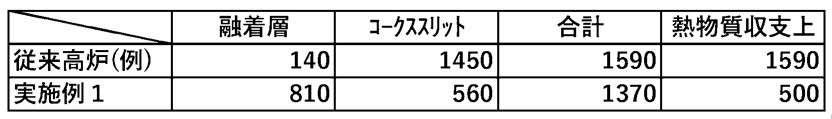
- FIG. 16 shows the heat balance in the lower part of the furnace between the conventional blast furnace and the present invention.
- the gas ratio passing through the cohesive zone is Vg >> Vg'
- Qcg' Qg'1 + Qk'1
- the primary combustion heat due to solid acid Qk and RW The total gas calorific value (sensible heat brought in and primary combustion heat) Qgr is significantly lower in the present invention. That is, in the present invention, the fuel ratio in the lower part of the reactor can be significantly reduced.
- FIG. 17 shows a Reichardt diagram of the lower part of the furnace of the present invention using a solid line. If the RW temperature Tg' decreases while the effective heat transfer amount (Qg'2 + Qg'3) to the lower part of the furnace remains constant, the gas operation line moves from the solid line to the two-dot chain line and the reactive heat Qg'1 increases. Therefore, for the same amount of effective heat transfer, a higher RW temperature Tg' (that is, a smaller RW gas amount Vg') is more advantageous in reducing the coke ratio and fuel ratio.
- Tg' further decreases and the gas operating line becomes less sloped than the two-dot chain line and falls below point A in the figure, it will no longer be possible to raise the temperature of the raw material to the tap iron slag temperature Ti', causing problems in operation.
- the operational lower limit of the RW temperature Tg' when the pig iron slag temperature Ti' 1500°C is approximately 2000°C, depending on the heat loss in the lower part of the furnace.
- iron ore is reduced by nearly 100% in the shaft, so the reduction reaction in the lower part of the furnace is limited to metals other than iron (P, Si, Mn, etc.). Therefore, the amount of heat Qh required in the lower part of the furnace is 700 to 1200 MJ/tp (650 to 950 MJ/tp excluding heat loss), although it varies depending on the slag ratio, pig iron temperature, pig slag composition, and furnace body heat loss. This is about 1/3 compared to 2500-3500MJ/tp.
- the major advantage of the present invention is that the process has been improved to significantly reduce the required heat in the lower part of the furnace and the amount of gas passing through the cohesive zone compared to conventional blast furnaces. This feature has made it possible to significantly reduce the coke ratio and fuel ratio.
- the ore if the ore reaches high temperatures, it will soften, the porosity will decrease, and the ventilation resistance will increase. Assuming that the softening start point of a 100% gas-reduced ore is 1350°C and the melting point is 1450°C, the longer the residence time and the higher the average temperature per residence time, the worse the air permeability becomes. Therefore, from the viewpoint of the air permeability of the fusion layer, it is desirable that the heat flow ratio be ⁇ 1, which can shorten the residence time at high temperatures.
- FIG. 18 shows a comparison between the conventional blast furnace and the present invention regarding the relationship between the amount of heat input to the lower part of the furnace other than the sensible heat of the ore (Qk + Qgr) and the required heat Qh in the lower part of the furnace.
- the heat input to the lower part of the furnace (Qk + Qgr) it is assumed that the effect of the present invention can be fully enjoyed up to a gas reduction rate of about 95%, and is shown as a solid line, and the case of a gas reduction rate of 100% is shown as a dotted line.
- the amount of heat input into the lower part of the furnace and the amount of gas have a strong correlation with the fuel ratio in the lower part of the furnace, but they are significantly reduced in the present invention.
- Examples 1 to 8 of the present invention, which will be described later, have a wide variety of fuel and reducing gas compositions, but all of them fall within the region within the dotted line.
- FIGS. 22 and 23 A comparison of the calorific value diagrams of the conventional blast furnace (example) and the present invention (example 1) results in FIGS. 22 and 23, respectively.
- the amount of heat (GJ/tp) on the vertical axis represents the enthalpy change of the raw material and gas in the furnace (that is, the amount of heat transfer between the two), and the horizontal axis represents the respective temperatures.
- the present invention by suppressing the primary combustion of C in the fuel, it is necessary to appropriately suppress the combustion temperature even in pure oxygen operation, while ensuring the raceway (RW) temperature at 2000°C or higher.
- RW raceway
- methane is not suitable as a tuyere-injected fuel because its primary combustion temperature is only about 400°C.
- Coal that has a lot of hidden moisture or attached water is not suitable as a fuel for the lower part of the furnace because the heat of decomposition of the moisture lowers the primary combustion temperature.
- the fuel used in the lower part of the furnace is oxy-combustion of ⁇ element metals (Si, Ca, Al, Mg, Fe, Si, Mn) or their alloys that make up pig iron and slag.'' That is also very beneficial. Since no by-product gas is generated during combustion, RW gas at any desired temperature can be produced by injecting it through the tuyere together with an appropriate amount of tuyere-injected gas. Furthermore, it goes without saying that the reason for selecting these fuels is that the by-products of these fuels are iron slag components and do not affect the quality of the iron slag.
- oxygen is injected at the same time as the fuel to burn up to CO (primary combustion) or to oxidize and burn the metal fuel. That is, it is characterized by injecting the following formula of oxygen per ton of pig iron depending on the composition of the tuyere-injected fuel.
- [O 2 ]f Amount of oxygen injected according to the tuyere-injected fuel (O 2 -kmol/tp)
- C1 Amount of C component in tuyere-injected fuel (C-kmol/tp)
- O1 Amount of O component in tuyere-injected fuel (O-kmol/tp)
- S1 Metallic Mg component in tuyere-injected fuel (Mg-kmol/tp)
- S2 Metallic Ca component in tuyere-injected fuel (Ca-kmol/tp)
- S3 Metal Si component in tuyere-injected fuel (Si-kmol/tp)
- S4 Metal Al component in tuyere-injected fuel (Al-kmol/tp)
- iron ore contains approximately 300 Nm 3 of oxygen (O 2 ) per ton of Fe, while conventional blast furnaces (direct reduction rate of approximately 30%) contain approximately 85 Nm 3 of oxygen (O 2 ).
- /tp solid oxygen directly consumes carbonaceous materials through direct reduction.
- the gas reduction rate can be stably brought close to 100%, so coke is not consumed by direct reduction. Therefore, as shown in the following equation, the coke can be burned in the lower part of the furnace by simply removing carbon, which is necessary for carburizing pig iron and reducing metal components other than iron (Si, Mn, P, etc.) in pig iron, from the coke ratio. Calculate the amount of oxygen required for
- [O 2 ]c Molar amount of oxygen blown depending on coke (O 2 -kmol/tp)
- C2 Carbon molar amount in coke (C-kmol/tp)
- C3 Carbon molar amount in pig iron (C-kmol/tp)
- C4 Carbon molar amount required for reduction of metals other than iron in pig iron (C-kmol/tp)
- the amount of oxygen Vo 2 (O 2 -kmol/tp) injected from the tuyere in the lower part of the furnace in the present invention is expressed as the sum of both equations ([O 2 ]f + [O 2 ]c) as shown in the following equation. Obviously, the amount of oxygen Vo 2 (O 2 -kmol/tp) injected from the tuyere in the lower part of the furnace in the present invention is expressed as the sum of both equations ([O 2 ]f + [O 2 ]c) as shown in the following equation. Become.
- Vo 2 0.5 x (C1 + C2 - C3 - C4 + S1 + S2 - O1) + S3 + 1.5 x S4 - (14)
- H 2 O and CO 2 may remain in the tuyere-injected gas. If H 2 O or CO 2 (assuming a total O2 kmol/tp) is injected from the tuyeres, that amount (O2 kmol/tp) of coke will be consumed, and the carbon content in the pig iron will also decrease. Take measures.
- the RW temperature here means an equilibrium gas temperature that includes not only the combustion of the tuyere-injected fuel but also cooling by the tuyere-injected gas, coke gasification reaction with surrounding coke, and combustion.
- the gas discharged from RW has the role of transmitting high-temperature heat (high-grade heat) to the material to generate and retain the heat of pig iron and slag, and the heat transfer rate is different between the gas and the material (pig iron, slag, coke ) is proportional to the temperature difference. Therefore, the gas temperature from the RW needs to be at least higher than the material temperature, and in the present invention, as explained in Fig. 17, it is controlled at about 2000°C or higher (assuming the tap iron slag temperature is 1500°C). Even if the reducing gas injected is preheated to 1300°C, it functions as a cooling gas relatively compared to the RW temperature. Therefore, similar to the explanation of FIG. 17, there is a restriction on the amount of gas blown into the tuyere in the lower part of the furnace.
- a means to solve the seemingly contradictory phenomena of the need to increase the amount of gas blown into the tuyere to promote gas reduction and reduce the reducing agent ratio and the need to restrict the amount of RW gas is to install multiple stages in the height direction. This is a method of installing tuyeres.
- FIG. 2 shows an example in which the tuyeres are divided into two or more stages in the height direction. Fuel and oxygen are blown into the first stage tuyere (lowest stage tuyere) 2a, and preheated reducing gas is blown into the first stage tuyere 2a installed below the cohesive zone 9 to keep the RW at an appropriate temperature. The remaining amount is blown into the tuyeres 2b to 2e of the second stage or higher installed above the cohesive zone 9.
- the temperature of the preheated reducing gas is preferably the ore temperature directly above the cohesive zone (1200 to 1350°C or higher) as explained in FIGS. 14 to 16.
- the multi-stage tuyere system of the present invention has the effect of ensuring the cohesive zone is in an inverted V-shape like the center coke charging method, which is characterized by ensuring ventilation inside the furnace. .
- the gas 3c originating from the third stage tuyere will flow on the furnace wall side, and the gas 3b originating from the second stage tuyere will flow through the middle part of the shaft.
- the gas temperature difference between the first-stage tuyere/second-stage tuyere/third-stage tuyere is replaced by a temperature difference in the furnace radial direction.
- a higher gas temperature means a higher reduction reaction rate and temperature increase rate, so the ore on the furnace center side, where the temperature is relatively higher, is higher than the ore on the furnace wall side, where the temperature is lower. It reaches its melting point quickly. Since the radial ore fall rate is approximately the same, early timing means a higher position in the furnace (closer to the charging port). Conversely, the furnace wall side reaches its melting point later, that is, at a lower position in the furnace (far from the charging port). Therefore, the cohesive zone forms an inverted V shape with excellent air permeability.
- the shape of the inverted V shape and the temperature inside the furnace can be adjusted depending on the temperature and air volume of each tuyere, the air volume ratio and temperature ratio of the first tuyere, second tuyere, and third tuyere, and the distance between the tuyeres.
- the distribution is determined (see Figure 3).
- a cohesive zone is formed between the first tuyere (bottom tuyere) and the second tuyere, so by installing the second tuyere and first tuyere close together, the cohesive zone Since the position can be fixed in the lower part of the furnace, the height of the furnace can be lowered. On the other hand, if the furnace height is the same, the preheating zone and reduction zone can be made longer, so productivity can be increased.
- the second stage tuyere 2b is preferably installed in the "recommended installation range of 2b" shown in FIG.
- the third stage tuyere is located at the bottom of the shaft located below the middle part in order to lengthen the gas reduction time (residence time) at temperatures below 1000°C (preferably 900°C or below) as described above. It is desirable to install it in the "2c recommended installation range" shown in FIG. 2, which is located above the "2b recommended installation range”.
- the reason why the blowing temperature of the second stage tuyere is set to 1200 to 1350°C (higher is desirable) is to reduce the heat consumption in the lower part of the furnace by adjusting the ore temperature to the cohesive zone. This is to raise the temperature to a similar temperature.
- the furnace top temperature it is desirable for the furnace top temperature to be as low as possible without condensing the gas in terms of energy consumption, and many blast furnaces operate at 120 to 180°C.
- the best temperature for the second stage tuyere injection is 1,300 to 1,350°C from the perspective of the heat balance in the lower part of the furnace, it must be lower than 1,200°C in order to control the furnace top gas temperature, W point temperature (Tr), and gas reduction end temperature ( There are cases where it is desired to inject at T23) (Examples 1 and 8 described later). In such cases, a three-stage tuyere is effective. While blowing the gas amount V2 at 1300°C (T2) from the second-stage tuyere in the bosch section, the gas amount is V3 is injected at a gas temperature (T3) of 1100°C or less. If the specific heat is constant, the relationship between these gas amounts and temperatures is as shown in the following equation.
- V23 V2+V3 -(16)
- T23 ⁇ V23 T2 ⁇ V2+T3 ⁇ V3 -(17)
- the gas amount V2 in the second stage tuyere should be managed so that the total gas amount (Vg + V2) with the cohesive zone passing gas ratio Vg is about 750 to 1000 Nm 3 /tp depending on the coke ratio. desirable.
- This is related to the heat flow ratio as explained above in Fig. 19, and if the heat flow ratio is >1 (the heat flow of the gas to the raw material is low), the raw material cannot be heated to the second stage tuyere gas temperature, and the furnace This is because the second stage tuyere flow rate is better to be small in order to lower the W point temperature (Tr) and gas reduction end temperature even when the required heat in the lower part increases and the heat flow ratio is ⁇ 1.
- gas reduction by H 2 is an endothermic reaction, so it may occur if there is a large hydrogen component in the tuyere-injected fuel or tuyere-injected gas (endothermic reduction) or if the coke ratio is high (heat flow ratio increases). ), the furnace top gas temperature decreases.
- the amount of injection into the first/second stage tuyeres is increased in order to raise the temperature of the furnace top gas (as a result, the amount of reducing gas increases, so the shaft efficiency ) or the temperature of the ore is raised using the pre-reducing tuyere 2d or the raw material preheating tuyere 2e shown in FIG.
- Preliminary reduction tuyere 2d is a tuyere installed between point M (starting point of magnetite reduction) and point W (starting point of reduction of wustite) on the Rist model, and is within the recommended installation range of ⁇ 2d'' shown in Figure 2. ” from the middle of the shaft to a range of ⁇ 1/6 of the shaft height.
- Hydrogen reduction is an endothermic reaction, and the heat is given from the gas, so with hydrogen-rich fuel, the temperature difference between the furnace top temperature and the W point temperature (Tr) becomes large.
- Tr the temperature difference between the furnace top temperature and the W point temperature
- the pre-reduction tuyeres only need to be able to pre-reduce to point W, so the degree of reduction of the gas only needs to be equal to or higher than the magnetite reduction equilibrium.
- the moisture content in the furnace top gas increases, so if the furnace top gas is washed and cooled as in conventional blast furnaces, rough dehydration can be easily performed and the degree of gas reduction can be increased. Therefore, the gas after cleaning and cooling is recirculated and the gas partially combusted with oxygen is blown into the same tuyere.
- the gas temperature in the preliminary reduction tuyeres is set to 1000°C or less (preferably 900°C or less).
- the advantage of the multi-stage tuyeres is that not only the furnace top temperature, but also the W point temperature (Tr) and gas reduction end temperature can be intentionally adjusted, which is a noteworthy point in the process.
- the reduction end temperature could be suppressed to 918°C, at which the coke gasification reaction is difficult to occur (see Figure A23).
- the amount of air blown into the first/second tuyere 2a, 2b was reduced to a heat flow ratio of 1 (the amount was increased by the third tuyere). ), the W point temperature (Tr) and reduction end temperature could be lowered by 100° C. or more while keeping the furnace top temperature the same as in Example 1 (dotted chain line in FIG. 23).
- the gas flow rate is controlled to reduce the amount of gas blown from the first-stage tuyere 2a and the second-stage tuyere 2b, and increase the amount of gas blown from the third-stage tuyere 2c.
- the W point temperature (Tr) and the gas reduction end temperature can be reduced.
- W Control to further reduce the point temperature (Tr) and gas reduction end temperature is possible.
- the operating system of this embodiment includes a plurality of tuyeres 2 each configured to blow reducing gas into the inside of a furnace body 1 of a blast furnace, the tuyeres being arranged at intervals in the circumferential direction of the furnace body 1. Three or more tuyere groups 2a, 2b, 2c, 2d arranged apart in the height direction of the furnace body 1 (vertical direction in FIG. 2), respectively.
- a tuyere blown gas flow rate adjustment system consisting of a flow rate measuring device for each tuyere group and a flow rate adjusting device for each tuyere group, and a flow meter FI7 to measure the top gas flow rate, and a component system CA8 (H 2 0), the flowmeter FI8, thermometer TI8, and pressure gauge PI8 to measure the furnace top gas oxidation degree, thermometer TI7 to measure the furnace top temperature, and thermometer TI5 to measure the temperature at the middle part of the shaft 12,
- a component system CA8 H 2 0
- the external fuel supply system measures the gas component CA9 and gas flow rate FI9 at the heater inlet, and the gas component CA11 and gas flow rate FI11 at the heater outlet, and supplies the required amount of fuel and oxygen O2 .
- a heating system including a heater 24, and a control system configured to control the tuyere blow gas flow regulation system.
- the gas reduction rate can be increased to nearly 100%, and the amount of gas, temperature, and fuel injected from the third-stage tuyere 2c and the preliminary reduction tuyere 2d can be controlled to While maintaining the temperature appropriately, the W point temperature (Tr) and the gas reduction end temperature can be controlled within the range of 600°C or more and 1000°C or less.
- the flow rate measuring devices for each tuyere group that constitute the tuyere blowing gas flow rate adjustment system are the flow meter FI12 that measures the flow rate of the tuyere group 2b shown in FIG. flowmeter FI13, flowmeter FI14, flowmeter FI11 (minus FI12 and FI13), flowmeter FI5, flowmeter FI6, which measures the flowrate of tuyere group 2d. , mass flowmeter WI6.
- the flow rate adjustment device for each tuyere group in the tuyere blowing gas flow rate adjustment system is a flow rate adjustment valve provided on the downstream side of each flow meter, as shown in FIG.
- the lower limit of the temperature range is 600°C or higher because it is difficult for the reduction reaction to proceed unless the ore temperature is 600°C or higher, and the upper limit of the temperature range is 1000°C or lower because the ore temperature is 600°C or higher. This is because the coke gasification reaction becomes active at a temperature of , and the temperature is controlled within this temperature range.
- the raw material preheating tuyere 2e is a tuyere installed in the upper 1/3 of the shaft above the pre-reduction tuyere 2d, and is not expected to perform pre-reduction, and is used for the purpose of preheating the raw material and controlling the furnace top temperature. It is to be installed. Since no gas reduction is expected, the advantage is that the gas used may have a low degree of gas reduction. Note that functionally, the pre-reducing tuyeres include the raw material preheating tuyeres, and as mentioned above, there is a great advantage in using the pre-reducing tuyeres, especially in hydrogen-rich operations.
- gas reduction is completed at a temperature (approximately 900 to 1000 degrees Celsius or less) at which the coke gasification reaction can be substantially suppressed kinetically by injecting fuel and reducing gas and controlling the furnace top gas.
- the major feature is that by doing so, the gas reduction rate can be brought as close to 100% as possible.
- the air permeability (ventilation pressure loss) of the cohesive zone is determined by the amount of gas passing through the cohesive zone and the ventilation resistance of the cohesive zone, in addition to the shape of the cohesive zone described above. In other words, reducing the amount of gas passing through the cohesive zone can lower the ventilation pressure loss, and by lowering the full-term resistance of the cohesive zone, the ventilation pressure loss can be reduced even with the same amount of gas.
- Non-Patent Document 3 states, ⁇ (1) The temperature at which the pressure drop starts to increase due to the softening and shrinkage phenomenon of the ore layer depends largely on the ore reduction rate (when the ore reduction rate approaches 100%), (>1300°C). (2) The pressure drop gradient (passage pressure loss per unit thickness) of the cohesive layer is large in conventional blast furnaces where the ore reduction rate is approximately 70% and in oxygen blast furnaces where the gas reduction rate is close to 100%. (In the former, the pressure drop gradient rises to 100 times the pressure drop gradient of the ore layer, but in the latter, the rise is only 10 times the pressure drop gradient of the ore layer.)
- gas from the second-stage tuyeres does not pass through the cohesive zone, and only gas from the first-stage tuyere (raceway) flows. Furthermore, since the oxygen blast furnace is nitrogen-free, the amount of gas in the furnace is reduced, so for example, in the case of Example 1 shown in Table 4 and Figure 6 below, the amount of gas passing through the cohesive zone is approximately 500Nm 3 /tp. This is approximately 30% of the conventional blast furnace (example) in the same table.
- Example 1 the coke ratio in Example 1 (the theoretical limit coke ratio required for carburizing pig iron and reducing metals other than iron) is approximately 20% of that of a conventional blast furnace, and the proportion of coke slits in the cohesive zone is proportional to that of the conventional blast furnace. decreases.
- Non-Patent Documents 6 to 8 The pressure drop gradient in the packed bed part of the blast furnace can be expressed by the following equation (Non-Patent Documents 6 to 8), and can also be applied to ore layers, coke layers, coke slits, and cohesive layers.
- ⁇ P Pressure loss (Pa/m)
- L Layer height or gas passage length (m)
- ⁇ Gas density (kg/m 3 )
- G Superficial mass flow rate (kg/m 2 ⁇ s)
- K Ventilation resistance index (see the following table; from non-patent documents 3, 12, 14)
- the pressure loss is calculated from the amount of gas passing through the cohesive zone of a conventional blast furnace (example) (the sum of gas 4a passing through the coke slit and gas 4b passing through the cohesive layer in Figure 1), and the same Table 2 shows the gas flow rate (Nm 3 /tp) passing through the cohesive zone of the present invention (Example 1), which results in pressure loss.
- the thickness L of the cohesive zone the thickness of the conventional blast furnace is twice that of the present invention in the same thermal calculation as in FIG.
- 30Nm 3 /tp is subtracted from the furnace top gas amount as gas derived from the coke gasification reaction above the cohesive zone.
- the cohesive zone pressure loss in Example 1 decreases according to the coke ratio, but the cohesive layer flow rate increases significantly, so the total required heat mass balance is reduced. Approximately 2.7 times as much gas flows as the amount of 500Nm 3 /tp. This means that at the required flow rate, the pressure loss will be reduced to 20% of that of a conventional blast furnace (example) (from equation (18)).
- the cohesive layer of the present invention is formed from ore with a reduction rate close to 100%, the melt from the cohesive layer (a low melting point compound made of unreduced FeO) that is conventionally found in blast furnaces drips into the coke slit and is aerated. Since phenomena that impede performance can be suppressed, the amount of ventilation is calculated based on the thickness ratio of the coke slit.
- Non-Patent Document 14 describes the physical characteristics, high temperature characteristics, charging method, etc.
- the greatest advantage of coke slits is ensuring the permeability of the cohesive zone, allowing Bosch gas (gas flowing into the cohesive zone) to bypass the cohesive layer with poor air permeability and pass through the coke slits.
- Bosch gas gas flowing into the cohesive zone
- the efficiency of heat exchange between the two is poor and there is a drawback as explained in FIG. 16 (increase in reactive heat in the lower part of the furnace). Due to poor heat exchange, the thickness of the fusion layer increases and pressure loss increases.
- the coke ratio is low and the permeability of the cohesive layer is high, so as shown in Table 2 below, more gas than the coke slit flows through the cohesive layer, dramatically eliminating the drawbacks of conventional blast furnaces. be done.
- Table 2 shows the total amount mixing method of the present invention, in which the entire amount of Bosch gas is passed through the fusion layer.
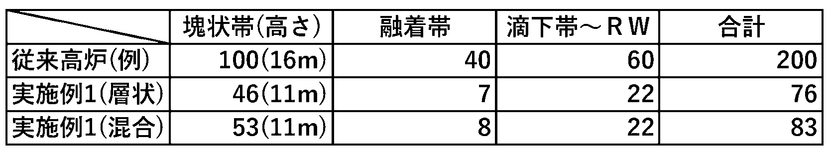
- Table 3 compares the pressure distribution (kPa) in the furnace of a conventional blast furnace (example) and the pressure distribution in the furnace when the raw materials of Example 1 were charged in layers and when the raw materials were charged in a mixed manner (without coke slits). Shown. Note that the charging raw material volume (m 3 /tp) per ton of pig iron varies depending on the coke ratio, and for example, in Example 1, it is 70% of that of the conventional blast furnace (example), so here the residence time of the lump band is constant. It is calculated by assuming the height of the lumpy band to be 70%.
- Example 1 The coke ratio in Example 1 is about 1/5 that of the conventional blast furnace (example), but in any charging method, the permeability is greatly improved compared to the conventional blast furnace (example), demonstrating the superiority of the present invention. This is the result.
- a decrease in ventilation pressure loss and an increase in residence time are, on the other hand, room for increased production, and if the present invention is applied to an existing blast furnace while keeping the pressure and furnace height unchanged, production can be increased by more than 40%. If production can be increased by 40%, the heat loss ratio in the lower part of the furnace (MJ/tp) can be reduced by 30%, and the required heat in the lower part of the furnace can be reduced by that amount, making it possible to further reduce the fuel ratio (10 kg/tp can be reduced in Example 1). , it also has great benefits from the perspective of reducing CO2 .
- the gas flow rate in the lower part of the furnace is reduced to about 1/2 to 1/3 of that of conventional blast furnaces, so the operation is free from flooding.
- flooding has been a factor that determines the tapping ratio, but in this respect as well, the present invention can increase the tapping ratio more than in conventional blast furnaces.
- Figure 4 shows the means to keep the gas reduction rate close to 100% and appropriately control fuel and oxygen.
- the measurement items are as follows. (The numbers in parentheses correspond to the instrument numbers in Figure 4)
- the H 2 O component of the gas (8) is determined from the vapor pressure of the furnace top gas (after dust removal and dehumidification) (8), and (7) is calculated.
- the H 2 O ratio in the furnace top gas (7) can be determined from the molar flow rate of (8).
- the oxygen (10) flow rate (FI_10) is the CO 2 molar flow rate and H 2 O molar flow rate of the gas (9) after the CO 2 separation equipment, as well as the molar flow rate of C, H, and O in the fuel (9). Adjust according to equation (11) so that the gas quality after heating is the best (consisting only of CO and H 2 ).
- Direct reduction ironmaking is a method of ironmaking in which only the gas reduction section of a blast furnace is removed.
- the reduction rate of reduced iron (DRI and HBI) produced by the direct reduction method is not 100% (about 95-97%).
- the main reason for this is that although the gas reduction rate is faster at higher temperatures, the ore temperature is kept below about 900°C for the purpose of suppressing sticking.In the present invention, there is no sticking restriction. Since gas reduction is possible up to temperatures just above the cohesive zone (approximately 1300°C), ore with a reduction rate of nearly 100% can be supplied to the lower part of the furnace.
- the enthalpy flow rate Q7 visible of the furnace top gas (7) is determined. heat and latent heat) can be calculated.
- Qfuel includes the latent heat flow rate Q4 from the fuel (4) injection speed (WI_4) and the latent heat flow rate Q6 from the fuel (6) injection speed (WI_6), and also includes the latent heat flow rate Q6 from the fuel (6) injection speed (WI_6).
- the heat required to make pig iron and slag from the start of softening must be at a high temperature of 2000°C or higher (high-grade heat) and is provided as the primary combustion of the first stage tuyere fuel and coke (Q4 + Q23). Furthermore, the rate of reduction reaction is faster at higher temperatures, and it is virtually difficult for the reaction to proceed unless the ore is preheated to 600°C or higher. Therefore, the coke (2) flow rate (WI_2) and fuel (4) are adjusted so that the temperature (TI_3) of the pig iron (1), the carbon content (CA_3), and the temperature (TI_5) under the preheating tuyere (5) become the required values. Adjust the flow rate (WI_4). At this time, adjust the oxygen (4) flow rate (FI_4) as shown in equation (10), and adjust the distribution ratio between the first-stage tuyere and the second-stage tuyeres and above so that the raceway temperature is appropriate. do.
- the preliminary reduction tuyere 2d is not used in principle. Keep the heater outlet gas (11) temperature (TI_11) at a high temperature, blow only through the first-stage tuyere 2a/second-stage tuyere 2b, and confirm that the furnace top temperature is within the appropriate range. If the temperature at the top of the furnace or the temperature at the middle part of the shaft (TI_5) is high, the respective flow rates (FI_13) and (FI_14) are distributed from the heater outlet gas and heater inlet gas as shown in Figure 4, and then mixed. Then, blow in from the third stage tuyere 2c at a temperature (TI_13). Thereby, the furnace top temperature ( ⁇ sensible heat loss of the furnace top gas) and the temperature below the middle part of the shaft ( ⁇ Tr temperature and final reduction temperature) can be lowered while the amount of blown reducing gas remains unchanged.
- the preliminary reduction tuyere 2d is used instead of the third stage tuyere 2c.
- the fuel (6) in the preliminary reduction tuyere is heated so that the furnace top gas (7) temperature reaches the required temperature.
- preheating the raw materials and supplying additional preliminary reduction heat has the effect of shifting not only the furnace top temperature but also the W point (the point at which FeO reduction begins) on the Rist model to the right. This leads to a reduction in the amount of reducing gas and a lower final reduction temperature (suppression of coke gasification reaction).
- the subsequent dehumidifier (including the gas cleaning cooler) Since it can be removed from the circulating gas as water, the influence of the feedstock preheating tuyere fuel can be limited to the dehumidifier from the top of the furnace. As described above, according to the present invention, stable and easy operation can be realized even at a much lower coke ratio and fuel ratio than in conventional blast furnaces.
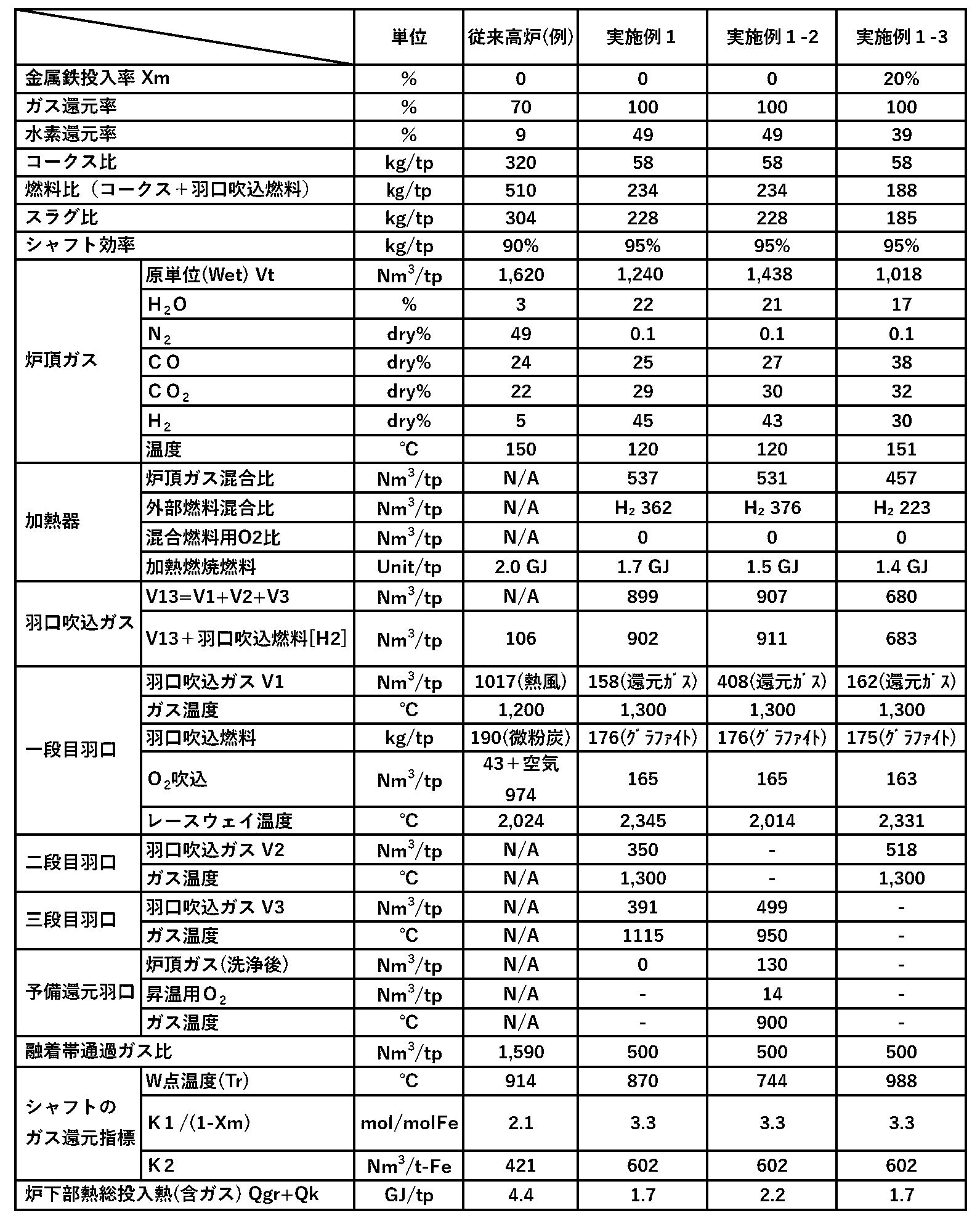
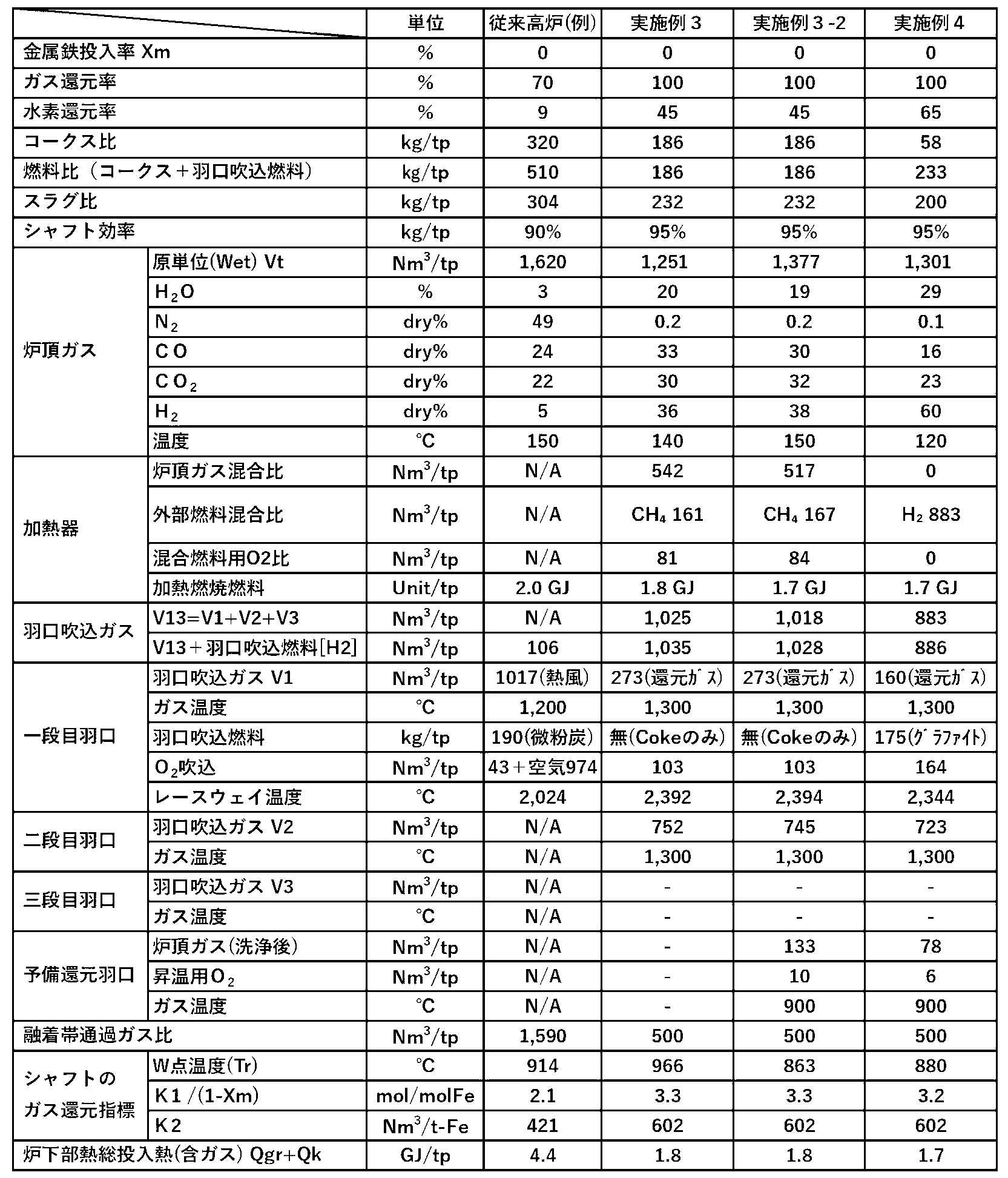
- Tables 4 to 7 show the basic unit and temperature of the examples of the present invention in comparison with examples of conventional blast furnaces.
- FIGS. 5 to 13 Flowcharts of the conventional blast furnace examples in Tables 4 to 7 and Examples 1 to 8 are shown in FIGS. 5 to 13, respectively (Examples 6 and 7 correspond to FIG. 12).
- the numbers in the figure indicate the basic unit for manufacturing 1 ton (1000 kg) of pig iron, and are part of the basic unit shown in Tables 4 to 7.
- Each basic unit was calculated using a heat-mass balance model for each zone, including the Rist model and heat balance calculation. However, for dehumidifiers, CO 2 separation equipment, gas reforming, and CO 2 recycling equipment, reaction efficiency was calculated. The basic unit is calculated as 100%.
- Example 1 is an example of the ultimate coke ratio in which the amount of coke used is limited to the amount of coke required for carburizing and reducing non-ferrous metals, and is an example of using graphite as a fuel.
- the carbon source (emitted during the process) is kept to the minimum necessary: coke.
- H 2 O is removed in a dehumidifier 21
- CO 2 is separated in a CO 2 separator 22
- the remaining components CO, H 2 , N 2
- the C (graphite) that has been reconverted into C (graphite) using graphite conversion equipment (for example, HAZER process) is reinjected into the furnace through the first stage tuyere 2a.
- the heater 24 is a regenerative furnace similar to the hot blast furnace 23 of the conventional blast furnace example (FIG. 5), and the heating fuel contains nitrogen contained in coal or coke and nitrogen mixed inside as a utility, which is concentrated by circulation.
- the furnace top gas extracted from the latter stage of the dehumidifier 21 is used, mixed with combustion exhaust gas for the purpose of flame temperature adjustment, oxidized combustion in a combustion chamber (not shown), and heated in a heat storage chamber (not shown).
- the CO 2 -rich exhaust gas is passed through a dehumidifier 21 if necessary, and then sent to a CO 2 recycling facility 25 .
- N 2 which is an impure gas is discharged from the system during the process of carbonic acid liquefaction (not shown), N 2 is not concentrated in the entire system.
- the furnace top gas from the CO 2 separator 22 is pressurized by the gas compressor 31, passes through another preheated heat storage chamber (not shown), is preheated to a predetermined temperature, and is supplied to each tuyere. .
- Example 1-2 in order to lower the W point temperature (Tr) and the reduction end temperature than in Example 1, the blowing amount of the third-stage tuyere and the first-stage tuyere was increased, and the second-stage tuyere was deleted.
- the second stage tuyere was deleted to simplify the equipment, the first stage tuyere may be returned to 158Nm 3 /tp and the second stage tuyere can be used to inject 250Nm 3 /tp.
- Example 1 Since both examples do not assume a coke gasification reaction, the amount of fossil fuel used in Example 1 is slightly smaller based on the trial calculation, but due to the difference between the W point temperature (Tr) and the reduction end temperature, actual operation is difficult. Then, there is a possibility that Example 1-2 is superior.
- the heater inlet gas and heater outlet gas are mixed in Figure 7, but if the hydrogen supply pressure is high, hydrogen is used instead of the heater inlet gas. may be mixed directly.
- Examples 1-3 to 1-5 are examples in which a certain proportion of the ore in Example 1 is replaced with metallic iron (DRI or scrap), and in Examples 1-3 and 1-4, metallic iron is used. 20%, and 36% for 1-5.
- Metallic iron does not require reduction and does not contain oxygen, so the heat capacity per ton of iron is small, so the heat flow ratio in the shaft decreases, which has the effect of offsetting the increase in heat flow ratio (shaft) due to oxygen blast furnaces and hydrogen reduction. .
- the amount of reducing gas in the shaft (lump zone) can be reduced, but the heat balance in the lower part of the furnace remains unchanged, so the fuel ratio remains almost the same.
- Tr W point temperature
- Example 1-5 is an example in which the proportion of metallic iron is further increased, and the lumpy zone is further cooled so that even if all the preheated reducing gas is blown into the first/second stage tuyeres, the Tr will reach the required temperature. However, since the temperature at the top of the furnace also decreases, preliminary reduction tuyeres are required.
- Example 2 is a case in which the tuyere-injected fuel (CO 2 recycled fuel) of Example 1 is not used.
- coke is used as a combustion heat source and reducing gas generation source, so the coke ratio is higher than in Example 1, but compared to a conventional blast furnace (example) that uses 190 kg/tp of pulverized coal,
- the fuel ratio (reducing agent ratio) has been reduced to 58% and the fuel ratio (reducing agent ratio) to 36%.
- Example 3 is a case in which the fuel in Example 2 was changed from hydrogen to methane. Utilizing hydrogen is essential for reducing CO2 , but it will be difficult to utilize hydrogen until infrastructure such as hydrogen production equipment and transportation systems is in place. Therefore, we presented a case using methane, which is highly available, including LNG.
- methane is directly injected into the furnace as tuyere fuel, but in this example, partial combustion (primary combustion; CO and H 2 generated) and mixed with the furnace top gas ( Figure 9).
- Example 3-2 shows a case in which Tr was reduced by 100°C or more by using a pre-reducing tuyere. Coke consumption is lower than in Example 2, but by using methane instead of hydrogen, CO 2 emissions excluding the CO 2 recycling effect are higher than in Example 2, but approximately 46% compared to the conventional blast furnace example. It can be reduced (Example 3-2).
- Example 4 is a case in which the entire amount of external hydrogen is used as the tuyere gas in Example 1 without using the furnace top gas.
- the furnace top gas (main components are H2, H2O , CO, and CO2 ) passes through the gas cleaning cooler 21a and is used as a byproduct gas as a fuel for the power generation equipment 26 outside the system, and is converted into H2O and CO2 .
- Exhausted as. H 2 O is removed from the exhaust gas in a dehumidifier 21 to turn it into CO 2 gas, which is converted to graphite (C) in a CO 2 recycling facility 25 and reused as tuyere-injected fuel.
- the electric power generated by the power generation equipment 26 is used in a hydrogen/oxygen production equipment 27 that produces H 2 and O 2 necessary for the blast furnace.
- the system is similar to Example 1 in that it does not emit any CO 2 into the atmosphere, but since the top gas is not recirculated within the blast furnace, CO 2 separation equipment is installed both on the blast furnace side and outside the system.
- the system is characterized by the fact that it is unnecessary.
- Example 5 shows a case using a metal fuel (powder) containing metal magnesium (Mg), metal calcium (Ca), and metal silicon (Si) in a slag component ratio.
- Example 5 in order to prevent the concentration of CO gas generated during the reduction of non-ferrous metals and impurity gases ( N2, etc.) that enter even slightly, a portion of the furnace top gas was heated using a heater as in Examples 1 and 3. Extracted as combustion gas.
- the CO 2 content in the heater combustion exhaust gas is small (several % vol)
- the gas is released from the gas chimney 28, but CO 2 can also be recovered by installing a dehumidifying device.
- the top gas contains CO 2 , albeit a small amount, CH 4 is blown into the latter stage of the heater to reform the gas, thereby suppressing the coke gasification reaction caused by CO 2 in the lower part of the furnace.
- the hydrogen reduction rate which is an endothermic reaction
- the second stage tuyere injection amount is increased (shaft efficiency decreases).
- the reducing gas is actively utilized from the preliminary reduction tuyeres.
- the heat flow ratio at the top of the shaft decreases to nearly 0.6 and the furnace top temperature rises slightly, but when the hydrogen reduction rate is 97%, the reduction start temperature is 650°C, the reduction end temperature is 900°C, and the furnace top temperature is 97%.
- Temperature ⁇ 200°C was realized based on heat mass balance and equilibrium theory.
- Examples 6 and 7 are cases in which an open system in which the top gas is not recirculated are used, and cases in which biofuels such as biocoke and biocoal are used for tuyere-injected fuel, and cases in which CO2 is converted into green power, respectively.
- biofuels such as biocoke and biocoal are used for tuyere-injected fuel
- CO2 is converted into green power, respectively.
- E-Fuel which has been converted into fuel, is used.
- These fuels are considered to have a CO 2 emission coefficient of zero (0), so only the reduction of non-ferrous metals is counted in the CO 2 emissions of the furnace top gas, so CO 2 must be recovered when being combusted and emitted. becomes unnecessary.
- the furnace top gas has an easy-to-use calorific value (8500 to 8700 kJ/Nm 3 in Examples 6 and 7), it can be widely used as an alternative energy source by using existing gas networks in factories other than blast furnaces. This has the advantage of significantly reducing CO 2 emissions from factories.
- Example 8 is a case in which the coke ratio and fuel ratio are reduced by using only the fuels (reducing agents) conventionally used in blast furnaces, such as coke, pulverized coal (PCI), and methane (equivalent to natural gas).
- Pulverized coal can be mixed with bio-coke or bio-coal in any ratio to create a mixed fuel, and if the final result is 100% biofuel, CO 2 emissions from tuyere-injected fuel will be zero. becomes (0).
- a similar effect can be achieved by switching methane, which is partially combusted in the heater and converted into reducing gas, to CO 2 recycled methane.
- the figure also shows the carbon (C) intensity before and after fuel conversion in their respective order.
- the above-mentioned embodiments are merely examples, and it is also possible to utilize intermediate raw materials and fuels or to configure a system by combining Examples 1 to 8.
- the present invention infinitely expands the options for raw materials and fuels and system configurations for reducing coke and CO2 , which is in itself revolutionary, and it is important to consider the future of CO2 storage/utilization technology as ancillary equipment.
- the optimal system can be adopted by adjusting the heat balance and material balance according to the development of the system, and taking economic efficiency into account.
- the technology according to the present invention can also be applied to reduced iron manufacturing equipment and cupolas (scrap melting furnaces).
Landscapes
- Engineering & Computer Science (AREA)
- Chemical & Material Sciences (AREA)
- Manufacturing & Machinery (AREA)
- Materials Engineering (AREA)
- Metallurgy (AREA)
- Organic Chemistry (AREA)
- Manufacture Of Iron (AREA)
Abstract
Description
(Cf+Cg-Ci)+(Hf+Hg)/2=1.5/ηg -(1)
に相当することにより達成される。
Cf:炉頂装入コークスと羽口吹込燃料を合わせた[C]量(mol-C/mol-Fe)
Hf:炉頂装入コークスと羽口吹込燃料を合わせた[H]量(mol-H/mol-Fe)
Cg:予熱還元ガス中のCOガス量(mol-C/mol-Fe)
Hg:予熱還元ガス中の[H]量(mol-H/mol-Fe)
Ci:銑鉄中の[C]量(mol-C/mol-Fe)
ηg:ガス利用率(%)または炉頂ガスの2次燃焼率(%)
である。ここで挙げたそれぞれの記号及び以下の段落中の記号Xm, K1は、銑鉄中の鉄(Fe)1モル当りに対する以下のモル数を表す。
(Cf+Cg-Ci)+(Hf+Hg)/2=1.5/ηg×(1-Xm) -(2)
と修正される。ここで、
Xm:炉頂装入原料中の全鉄分(mol-Fe)に対する金属鉄(mol-Fe)の割合
である。
(Cf+Cg-Ci)+(Hf+Hg)/2 = K1×(1-Xm) -(3)
3.9≧K1≧3.1 -(4)
である。ここで、
K1:燃料比を決める際の定数
である。
Psh =(Pd×MR)/Vsh ≦ 12 (t原料/day・m3) -(5)
Pd:1日当りの銑鉄生産量(tp/day)
MR:炉頂装入原料比(t/tp)
Vpc=K2×Gy/1.5+Xf×22.4+Xo -(6)
610≧K2≧560 -(7)
Gy:装入鉱石ならびに装入金属鉄の鉄分(mol-Fe)に対する酸素(mol-O)の割合(mol-O/mol-Fe)
Xf:銑鉄1t当りの装入原料に含まれるCaCO3、MgCO3の合計モル比(kmol/tp)
Xo:シャフトの上から2/3高さ(下から1/3高さ)より上方にて炉内供給される2次燃焼ガス(CO2、H2O)のガス量(Nm3/tp)
j/i ≦ 2.3、 -(8)
(16×k)/(12×i+j+16×k) ≦ 10% -(9)
Vo2=0.5×(C1+C2-C3-C4+S1+S2-O1-O2)+S3+1.5×S4 -(10)
C2:コークス中の炭素モル量(C-kmol/tp)
C3:銑鉄中の炭素モル量(C-kmol/tp)
C4:銑鉄中の鉄以外金属の還元に必要な炭素モル量(C-kmol/tp)
O1:羽口吹込燃料中のO成分量(O-kmol/tp)
O2:予熱還元ガス中のCO2とH2Oのモル量(kmol/tp)
S1:羽口吹込燃料中の酸素と結びついていないMg成分(Mg-kmol/tp)
S2:羽口吹込燃料中の酸素と結びついていないCa成分(Ca-kmol/tp)
S3:羽口吹込燃料中の酸素と結びついていないSi成分(Si-kmol/tp)
S4:羽口吹込燃料中の酸素と結びついていないAl成分(Al-kmol/tp)
[CO2](kmol /Nm3) :炉頂ガス中のCO2成分
[H2O](kmol /Nm3) :炉頂ガス中のH2O成分
[C](kmol /kg) :燃料中のC成分
[O](kmol /kg) :燃料中のO成分
C+ 0.5×O2 = CO ;反応熱(発熱)はQkに含まれる
C1:羽口吹込燃料中のC成分量(C-kmol/tp)
O1:羽口吹込燃料中のO成分量(O-kmol/tp)
S1:羽口吹込燃料中の金属Mg成分(Mg-kmol/tp)
S2:羽口吹込燃料中の金属Ca成分(Ca-kmol/tp)
S3:羽口吹込燃料中の金属Si成分(Si-kmol/tp)
S4:羽口吹込燃料中の金属Al成分(Al-kmol/tp)
C2:コークス中の炭素モル量(C-kmol/tp)
C3:銑鉄中の炭素モル量(C-kmol/tp)
C4:銑鉄中の鉄以外金属の還元に必要な炭素モル量(C-kmol/tp)
2)羽口吹込燃料を炭素成分見合いでO2 (kmol/tp)増やす。
[O2]f=0.5×(C1+S1+S2-O1-O2)+S3+1.5×S4 -(15-1)
[O2]c=0.5×(C2-C3-C4) -(15-2)
T23×V23=T2×V2+T3×V3 -(17)
L :層の高さまたはガス通過長さ(m)
ρ :ガス密度(kg/m3)
G :空塔質量流量速度(kg/m2・s)
K :通気抵抗指数(次表参照;非特許文献3、12、14より)

(2)コークス中[C][H][O]成分(CA_2)と投入速度(WI_2)
(3)銑鉄の温度(TI_3)と[C]成分(CA_3)
(4)羽口吹込燃料の[C][H][O]成分(CA_4)と投入速度(WI_4)、酸素流量(FI_4)
(5)予備還元羽口下部の炉内温度(TI_5)と同羽口への炉頂ガス再循環流量(FI_5)
(6)予備還元羽口吹込燃料の[C][H][O]成分(CA_6)と投入速度(WI_6)、酸素流量(FI_6)
(7)炉頂ガス流量(FI_7)と温度(TI_7)、ガス圧力(PI_7)
(8)除塵・除湿後の炉頂ガス流量(FI_8)と温度(TI_8)、ガス圧力(PI_8)、ガス成分(CA_8)
(9)CO2分離後の炉頂ガス流量(FI_9)とガス成分(CA_9)
(10)炉頂ガスに混合する燃料の[C][H][O]成分(C10_10)と投入速度(WI_10)、酸素流量(FI_10)
(11)加熱器出側ガスの流量(FI_11)、温度(TI_11)、圧力(PI_11)、[CO2]成分(CA_11)
(12)二段目羽口吹込ガス流量(FI_12)
(13)三段目羽口へ送る高温ガス流量(FI_13)と吹込み前温度(TI_13)
(14)三段目羽口へ送る低温ガスの流量(FI_14)と温度(TI_14)
(15)炉頂ガスから系外に抽出されるガス流量(FI_15)


Claims (10)
- 炉頂装入コークスまたは羽口吹込燃料あるいはその両方以外に、800℃以上に予熱された還元ガスを羽口から炉内に吹込む高炉の操業方法であって、
シャフトの生産性((Pd×MR)/Vsh)を、
不等式(Pd×MR)/Vsh ≦ 12、
ただし、
Vsh:前記シャフトの有効炉容積(m3)、
Pd:1日当りの銑鉄生産量(tp/day)、
MR:炉頂装入原料比(t/tp)、
を満たすように制御し、
前記還元ガスを、前記シャフトの中間部より上方に吹込むガスを含めない量として、
不等式3.9≧K1≧3.1、
ただし、銑鉄中の鉄1モルに対し、
式(Cf+Cg-Ci)+(Hf+Hg)/2 = K1×(1-Xm)、
K1:燃料比を決める際の定数、
Cf:前記炉頂装入コークスと前記羽口吹込燃料を合わせた[C]量(mol-C/mol-Fe)、
Hf:前記炉頂装入コークスと前記羽口吹込燃料を合わせた[H]量(mol-H/mol-Fe)、
Cg:前記還元ガス中のCOガス量(mol-C/mol-Fe)、
Hg:前記還元ガス中の[H]量(mol-H/mol-Fe)、
Ci:銑鉄中の[C]量(mol-C/mol-Fe)、
Xm:炉頂装入原料中の全鉄分(mol-Fe)に対する金属鉄(mol-Fe)の割合、
を満たす量となるよう吹き込む、
ことを含む、操業方法。 - 前記銑鉄中の鉄1t当りの炉頂ガス中のCO2とH2Oの合計ガス量Vpc=K2×Gy/1.5+Xf×22.4+Xo (Nm3/t-Fe)において、
不等式610≧K2≧560、
ただし、
K2:直接還元率や銑鉄中の鉄割合により決まる定数、
Gy:装入鉱石ならびに装入金属鉄の鉄分(mol-Fe)に対する酸素(mol-O)の割合(mol-O/mol-Fe)、
Xf:銑鉄1t当りの装入原料に含まれるCaCO3、MgCO3の合計モル比(kmol/tp)、
Xo:シャフトの上から2/3の高さ(下から1/3高さ)より上方の位置において炉外から供給される2次燃焼ガスのガス量(Nm3/tp)、
を満たすように前記還元ガスの前記量をさらに調整する、
ことをさらに含む、請求項1に記載の操業方法。 - 炉下部での1次燃焼熱量と羽口吹込ガス顕熱との合計熱量を銑鉄1トン当たり2.4GJ/tp以下にする、
ことをさらに含む、請求項1または2に記載の操業方法。 - 前記シャフトならびに炉下部を含めた炉体に、高さ方向に前記羽口を2段以上配置し、
前記羽口のうちの最下段の羽口から酸素と2次燃焼ガスの合計量として200Nm3/tp以下の酸素含有ガスを吹き込み、
前記還元ガスのうち、シャフト下部より下方の羽口から500×(1-Xm)1.3Nm3/tp以上、ならびに前記還元ガスと前記羽口吹込燃料中の水素分を含めたCOとH2の合計が800×(1-Xm)1.3Nm3/tp以上になるよう吹き込む
ただし、
Xm:炉頂装入原料中の全鉄分(mol-Fe)に対する金属鉄(mol-Fe)の割合、
ことをさらに含む、請求項1または2に記載の操業方法。 - 前記シャフトならびに前記炉下部を含めた炉体に、高さ方向に前記羽口を2段以上配置し、
前記羽口のうちの最下段の羽口から酸素と2次燃焼ガスの合計量として200Nm3/tp以下の酸素含有ガスを吹き込み、
前記還元ガスのうち、シャフト下部より下方の羽口から500×(1-Xm)1.3Nm3/tp以上、ならびに前記還元ガスと前記羽口吹込燃料の中の水素分を含めたCOとH2の合計が800×(1-Xm)1.3Nm3/tp以上になるよう吹き込む
ただし、
Xm:炉頂装入原料中の全鉄分(mol-Fe)に対する金属鉄(mol-Fe)の割合、
ことをさらに含む、請求項3に記載の操業方法。 - 前記還元ガスの少なくとも一部を、融着帯より上の前記羽口と前記融着帯より下の前記羽口を通して1200℃以上において吹き込む、
ことをさらに含む、請求項1~5の何れか一項に記載の操業方法。 - 前記羽口吹込燃料として、化学式CiHjOkで表され、
灰成分を除いた表示として、
j/i≦2.3、
(16×k)/(12×i+j+16×k)≦10%、
を満たす炭化水素系燃料、Si,Ca,Al,Mg,Fe,Si,Mn,Cより選択された一以上を含む合金鉄、または前記炭化水素系燃料と前記合金鉄とを含む混合燃料を、酸素と共に使用する、
ことをさらに含む、請求項1~6の何れか一項に記載の操業方法。 - 銑鉄1トンあたり、
式Vo2=[O2]f + [O2]c、
ただし、
[O2]f=0.5×(C1+S1+S2-O1-O2)+S3+1.5×S4、
[O2]c=0.5×(C2-C3-C4)、
C1:前記羽口吹込燃料中のC成分量(C-kmol/tp)、
C2:コークス中の炭素モル量(C-kmol/tp)、
C3:銑鉄中の炭素モル量(C-kmol/tp)、
C4:銑鉄中の鉄以外金属の還元に必要な炭素モル量(C-kmol/tp)、
O1:前記羽口吹込燃料中のO成分量(O-kmol/tp)、
O2:前記予熱された還元ガス中のCO2とH2Oのモル量(kmol/tp)、
S1:前記羽口吹込燃料中の酸素と結びついていないMg成分(Mg-kmol/tp)、
S2:前記羽口吹込燃料中の酸素と結びついていないCa成分(Ca-kmol/tp)、
S3:前記羽口吹込燃料中の酸素と結びついていないSi成分(Si-kmol/tp)、
S4:前記羽口吹込燃料中の酸素と結びついていないAl成分(Al-kmol/tp)、
を満たす量に対して-1(O2-kmol/tp)~+0.2(O2-kmol/tp)の範囲の量の酸素であって純度90%以上の酸素を、前記羽口吹込燃料および前記予熱された還元ガスとともに、前記炉内に吹き込む、
ことをさらに含む、請求項1~7の何れか一項に記載の操業方法。 - 前記炉頂装入コークスの全量を、副原料を含む鉱石と混合して前記炉内に装入する、
ことをさらに含む、請求項1~8の何れか一項に記載の操業方法。 - 請求項1~9の何れか一項に記載の操業方法を実施するためのシステムであって、
それぞれ前記高炉の炉体の内部に還元ガスを吹き込むべく構成された複数の羽口であって、前記炉体の周方向に間隔をおいて並べられた羽口よりそれぞれなる羽口群であって、前記炉体の高さ方向に離れて配置された3以上の羽口群、ならびに、前記羽口群毎の流量計測機器と前記羽口群毎の流量調整機器から構成される羽口吹込ガス流量調整システムと、
炉頂ガス流量と、炉頂ガス酸化度と、炉頂温度と、シャフトの中間部の温度とを計測して外部燃料供給システムと加熱システムならびに前記羽口吹込ガス流量調整システムを制御するべく構成された制御システムと、
を備えた操業システム。
Priority Applications (4)
| Application Number | Priority Date | Filing Date | Title |
|---|---|---|---|
| CN202380031218.0A CN119677877A (zh) | 2022-03-31 | 2023-03-30 | 气体还原高炉及其操作方法 |
| JP2023550126A JP7445842B2 (ja) | 2022-03-31 | 2023-03-30 | ガス還元高炉およびその操業方法 |
| EP23780848.0A EP4502185A4 (en) | 2022-03-31 | 2023-03-30 | GAS REDUCTION BLAST FURNACE AND ITS OPERATING METHOD |
| KR1020247036163A KR20240169087A (ko) | 2022-03-31 | 2023-03-30 | 가스 환원 고로 및 그 조업 방법 |
Applications Claiming Priority (2)
| Application Number | Priority Date | Filing Date | Title |
|---|---|---|---|
| JP2022068527 | 2022-03-31 | ||
| JP2022-068527 | 2022-03-31 |
Publications (1)
| Publication Number | Publication Date |
|---|---|
| WO2023190840A1 true WO2023190840A1 (ja) | 2023-10-05 |
Family
ID=88202829
Family Applications (1)
| Application Number | Title | Priority Date | Filing Date |
|---|---|---|---|
| PCT/JP2023/013118 Ceased WO2023190840A1 (ja) | 2022-03-31 | 2023-03-30 | ガス還元高炉およびその操業方法 |
Country Status (6)
| Country | Link |
|---|---|
| EP (1) | EP4502185A4 (ja) |
| JP (1) | JP7445842B2 (ja) |
| KR (1) | KR20240169087A (ja) |
| CN (1) | CN119677877A (ja) |
| TW (1) | TW202409298A (ja) |
| WO (1) | WO2023190840A1 (ja) |
Cited By (1)
| Publication number | Priority date | Publication date | Assignee | Title |
|---|---|---|---|---|
| WO2025047735A1 (ja) | 2023-08-28 | 2025-03-06 | 株式会社SimpLE研 | 原料の事前処理方法 |
Families Citing this family (1)
| Publication number | Priority date | Publication date | Assignee | Title |
|---|---|---|---|---|
| DE102024121592A1 (de) * | 2024-07-30 | 2026-02-05 | Hatch Ltd. | Reaktor zur gasbasierten direktreduktion in einem druckbeaufschlagten gegenstromschachtofen |
Citations (6)
| Publication number | Priority date | Publication date | Assignee | Title |
|---|---|---|---|---|
| JPS5722867U (ja) | 1980-07-12 | 1982-02-05 | ||
| JPH0394006A (ja) * | 1989-09-05 | 1991-04-18 | Sumitomo Metal Ind Ltd | 高炉羽口粉体吹き込み方法 |
| JP2015129325A (ja) * | 2014-01-07 | 2015-07-16 | 新日鐵住金株式会社 | 高炉の操業方法 |
| JP2016168281A (ja) | 2015-03-13 | 2016-09-23 | オムロン株式会社 | 制御装置、制御装置の制御方法、制御プログラムおよび記録媒体 |
| JP2018070952A (ja) * | 2016-10-28 | 2018-05-10 | Jfeスチール株式会社 | 高炉操業方法及び高炉設備 |
| JP2022068527A (ja) | 2020-10-22 | 2022-05-10 | 株式会社Cureapp | 薬の摂取量を調整するためのシステム、電子装置、方法及びプログラム |
Family Cites Families (2)
| Publication number | Priority date | Publication date | Assignee | Title |
|---|---|---|---|---|
| JPH0790034A (ja) | 1994-04-28 | 1995-04-04 | Shiro Kobayashi | ポリエチレンイミン誘導体鎖をグラフト鎖として有するグラフトポリマー及びその製造方法 |
| US6030430A (en) * | 1998-07-24 | 2000-02-29 | Material Conversions, Inc. | Blast furnace with narrowed top section and method of using |
-
2023
- 2023-03-30 CN CN202380031218.0A patent/CN119677877A/zh active Pending
- 2023-03-30 KR KR1020247036163A patent/KR20240169087A/ko active Pending
- 2023-03-30 WO PCT/JP2023/013118 patent/WO2023190840A1/ja not_active Ceased
- 2023-03-30 EP EP23780848.0A patent/EP4502185A4/en active Pending
- 2023-03-30 TW TW112112284A patent/TW202409298A/zh unknown
- 2023-03-30 JP JP2023550126A patent/JP7445842B2/ja active Active
Patent Citations (6)
| Publication number | Priority date | Publication date | Assignee | Title |
|---|---|---|---|---|
| JPS5722867U (ja) | 1980-07-12 | 1982-02-05 | ||
| JPH0394006A (ja) * | 1989-09-05 | 1991-04-18 | Sumitomo Metal Ind Ltd | 高炉羽口粉体吹き込み方法 |
| JP2015129325A (ja) * | 2014-01-07 | 2015-07-16 | 新日鐵住金株式会社 | 高炉の操業方法 |
| JP2016168281A (ja) | 2015-03-13 | 2016-09-23 | オムロン株式会社 | 制御装置、制御装置の制御方法、制御プログラムおよび記録媒体 |
| JP2018070952A (ja) * | 2016-10-28 | 2018-05-10 | Jfeスチール株式会社 | 高炉操業方法及び高炉設備 |
| JP2022068527A (ja) | 2020-10-22 | 2022-05-10 | 株式会社Cureapp | 薬の摂取量を調整するためのシステム、電子装置、方法及びプログラム |
Non-Patent Citations (15)
Cited By (1)
| Publication number | Priority date | Publication date | Assignee | Title |
|---|---|---|---|---|
| WO2025047735A1 (ja) | 2023-08-28 | 2025-03-06 | 株式会社SimpLE研 | 原料の事前処理方法 |
Also Published As
| Publication number | Publication date |
|---|---|
| TW202409298A (zh) | 2024-03-01 |
| EP4502185A4 (en) | 2025-07-23 |
| EP4502185A1 (en) | 2025-02-05 |
| KR20240169087A (ko) | 2024-12-02 |
| JP7445842B2 (ja) | 2024-03-08 |
| CN119677877A (zh) | 2025-03-21 |
| JPWO2023190840A1 (ja) | 2023-10-05 |
Similar Documents
| Publication | Publication Date | Title |
|---|---|---|
| LU500699B1 (en) | Method for operating a shaft furnace plant | |
| US6986800B2 (en) | Method and apparatus for improved use of primary energy sources in integrated steel plants | |
| AU2011309835B2 (en) | Method and apparatus for producing direct reduced iron utilizing a source of reducing gas comprising hydrogen and carbon monoxide | |
| JP7445842B2 (ja) | ガス還元高炉およびその操業方法 | |
| CN104412056A (zh) | 利用炉顶煤气再循环的高炉 | |
| TWI864000B (zh) | 用於操作高爐的方法 | |
| CN101906501A (zh) | 一种用粉矿和煤氧直接炼钢工艺 | |
| US20240360526A1 (en) | Method for operating a metallurgical plant for producing iron products | |
| JP2015525829A (ja) | 炉頂ガス再循環および燃焼式管状加熱炉を備える高炉を運転する方法およびシステム | |
| CN101448962B (zh) | 通过注入含烃气体制造铁水的方法和使用该方法制造铁水的设备 | |
| JP2000212615A (ja) | 製鉄設備排ガスからのエネルギ―回収方法 | |
| CN102586528A (zh) | 一种天然气熔融还原炼铁新工艺 | |
| WO2019150204A1 (ru) | Технология безазотной плавки чугуна с вдуванием в домну кислорода и оксида углерода | |
| JP2025530034A (ja) | 製錬炉設備を操業するための方法 | |
| CN119731343A (zh) | 用于操作冶炼炉设施的方法 | |
| KR20100082696A (ko) | 용광로에서의 철 제조방법 및 이 제조방법으로부터 얻어지는 상부 가스의 사용방법 | |
| WO2023162389A1 (ja) | 粉鉄鉱石の還元方法 | |
| JP7827130B2 (ja) | 高炉の操業方法 | |
| RU2854232C2 (ru) | Способ управления продувкой для плавки в доменной печи | |
| IT202300020244A1 (it) | Processo di riduzione di minerale di ferro alimentato con idrogeno | |
| EA050926B1 (ru) | Способ эксплуатации установки доменной печи | |
| Riley et al. | Iron Production | |
| GB2428428A (en) | Methods of operating a zinc-producing blast furnace | |
| KR20120074645A (ko) | 합성가스를 이용한 환원철 제조장치 및 이를 이용한 환원철 제조방법 | |
| JPH0215106A (ja) | 溶銑の製造方法 |
Legal Events
| Date | Code | Title | Description |
|---|---|---|---|
| WWE | Wipo information: entry into national phase |
Ref document number: 2023550126 Country of ref document: JP |
|
| 121 | Ep: the epo has been informed by wipo that ep was designated in this application |
Ref document number: 23780848 Country of ref document: EP Kind code of ref document: A1 |
|
| WWE | Wipo information: entry into national phase |
Ref document number: 202380031218.0 Country of ref document: CN |
|
| REG | Reference to national code |
Ref country code: BR Ref legal event code: B01A Ref document number: 112024020052 Country of ref document: BR |
|
| ENP | Entry into the national phase |
Ref document number: 20247036163 Country of ref document: KR Kind code of ref document: A |
|
| WWE | Wipo information: entry into national phase |
Ref document number: 202417082943 Country of ref document: IN |
|
| WWE | Wipo information: entry into national phase |
Ref document number: 2023780848 Country of ref document: EP |
|
| ENP | Entry into the national phase |
Ref document number: 2023780848 Country of ref document: EP Effective date: 20241031 |
|
| NENP | Non-entry into the national phase |
Ref country code: DE |
|
| REG | Reference to national code |
Ref country code: BR Ref legal event code: B01E Ref document number: 112024020052 Country of ref document: BR Free format text: APRESENTAR, EM ATE 60 (SESSENTA) DIAS, NOVAS FOLHAS DOS DESENHOS ADAPTADAS AO ART. 39 DA INSTRUCAO NORMATIVA 31/2013 UMA VEZ QUE O CONTEUDO ENVIADO NA PETICAO NO 870240082742 DE 27/09/2024 ENCONTRA-SE FORA DA NORMA. |
|
| REG | Reference to national code |
Ref country code: BR Ref legal event code: B01Y Ref document number: 112024020052 Country of ref document: BR Kind code of ref document: A2 Free format text: ANULADA A PUBLICACAO CODIGO 1.5 NA RPI NO 2820 DE 21/01/2025 POR TER SIDO INDEVIDA. |
|
| ENP | Entry into the national phase |
Ref document number: 112024020052 Country of ref document: BR Kind code of ref document: A2 Effective date: 20240927 |
|
| WWP | Wipo information: published in national office |
Ref document number: 202380031218.0 Country of ref document: CN |