WO2023199378A1 - 遮断器および遮断方法 - Google Patents
遮断器および遮断方法 Download PDFInfo
- Publication number
- WO2023199378A1 WO2023199378A1 PCT/JP2022/017505 JP2022017505W WO2023199378A1 WO 2023199378 A1 WO2023199378 A1 WO 2023199378A1 JP 2022017505 W JP2022017505 W JP 2022017505W WO 2023199378 A1 WO2023199378 A1 WO 2023199378A1
- Authority
- WO
- WIPO (PCT)
- Prior art keywords
- circuit breaker
- directions
- power
- slots
- circuit
- Prior art date
- Legal status (The legal status is an assumption and is not a legal conclusion. Google has not performed a legal analysis and makes no representation as to the accuracy of the status listed.)
- Ceased
Links
Images


Classifications
-
- H—ELECTRICITY
- H01—ELECTRIC ELEMENTS
- H01H—ELECTRIC SWITCHES; RELAYS; SELECTORS; EMERGENCY PROTECTIVE DEVICES
- H01H71/00—Details of the protective switches or relays covered by groups H01H73/00 - H01H83/00
- H01H71/02—Housings; Casings; Bases; Mountings
- H01H71/0264—Mountings or coverplates for complete assembled circuit breakers, e.g. snap mounting in panel
- H01H71/0271—Mounting several complete assembled circuit breakers together
-
- H—ELECTRICITY
- H01—ELECTRIC ELEMENTS
- H01H—ELECTRIC SWITCHES; RELAYS; SELECTORS; EMERGENCY PROTECTIVE DEVICES
- H01H33/00—High-tension or heavy-current switches with arc-extinguishing or arc-preventing means
- H01H33/02—Details
- H01H33/59—Circuit arrangements not adapted to a particular application of the switch and not otherwise provided for, e.g. for ensuring operation of the switch at a predetermined point in the AC cycle
Definitions
- the present invention relates to a circuit breaker and a circuit breaker method.
- the disclosed technology aims to simplify the configuration of a circuit breaker that branches in multiple directions.
- the disclosed technology includes a cutoff unit for cutting off current in two directions, a plurality of slots into which the cutoff units are inserted, and connections between different points depending on the slots into which the cutoff units are inserted.
- the circuit breaker includes a casing including a pre-wired circuit.
- FIG. 1 is a diagram showing an example of the configuration of a power feeding system according to the present embodiment. It is a diagram showing a circuit breaker branching in two directions.
- FIG. 3 is a diagram showing a circuit breaker branching into three directions. It is a diagram showing a circuit breaker branching in four directions.
- FIG. 2 is a diagram showing an example of the appearance of a case of a circuit breaker according to Example 1 of the embodiment of the present invention.
- FIG. 2 is a first diagram showing an example of the internal wiring of the case of the circuit breaker according to Example 1 of the embodiment of the present invention. It is a figure showing an example of a conventional cutoff unit.
- FIG. 2 is a diagram showing an example of an internal circuit of a conventional cutoff unit.
- FIG. 1 is a diagram showing an example of a conventional bidirectional power feeding system.
- FIG. 2 is a sequence diagram illustrating an example of a handshake flow in a conventional bidirectional power supply system.
- FIG. 7 is a first diagram for explaining a method for determining a power feeding route according to Example 2 of the embodiment of the present invention.
- FIG. 7 is a second diagram for explaining a method for determining a power feeding route according to Example 2 of the embodiment of the present invention.
- FIG. 7 is a diagram for explaining a method of locking a power supply path and setting protection coordination according to Example 2 of the embodiment of the present invention.
- FIG. 1 is a diagram showing an example of a hardware configuration of a computer.
- FIG. 2 is a diagram for explaining a conventional cutoff circuit.
- FIG. 2 is a diagram for explaining a conventional branch breaker circuit. It is a figure which shows an example of the branch cutoff circuit based on Example 3 of embodiment of this invention. It is a figure which shows an example of the housing
- circuit breaker according to this embodiment may be a DC circuit breaker or an AC circuit breaker.
- the method of the circuit breaker according to this embodiment may be any of a mechanical type, a hybrid type, and a semiconductor type.
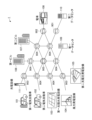
- FIG. 1 is a diagram showing an example of the configuration of a power feeding system according to the present embodiment.
- the power source, load, etc. are, for example, the first electric vehicle 101, the second electric vehicle 102, the first solar power generation facility 103, the wind power generation facility 104, the second solar power generation facility 105, and the first building 106. , a second building 107 , a train 108 , a first data center 109 , a second data center 110 , and a charging facility 111 .
- Circuit breakers are installed at branch points of the power supply network.
- the two-way circuit breaker 901 is a circuit breaker that branches in two directions.
- a three-way circuit breaker 902 that branches in three directions
- a four-way circuit breaker 903 that branches in four directions
- a five-way circuit breaker 904 that branches in five directions
- a six-way circuit breaker 905 that branches in six directions are connected to the power supply network. installed at each branch point.
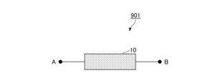
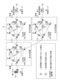
- FIG. 2 is a diagram showing a circuit breaker branching in two directions.
- the two-way circuit breaker 901 includes one interrupting unit 10.
- the cutoff unit 10 is connected between AB.
- the cutoff unit 10 can cut off current in two directions, from A to B and from B to A.
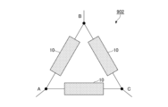
- FIG. 3 is a diagram showing a circuit breaker branching into three directions.
- Three-way circuit breaker 902 includes three interrupting units 10. Each cutoff unit 10 is connected between AB, BC, and AC, respectively. Each cutoff unit 10 can cut off current in two directions between two connected points. Thereby, the three-way circuit breaker 902 can interrupt currents in all combinations of the three points A, B, and C.
- FIG. 4 is a diagram showing a circuit breaker branching in four directions.
- the four-way circuit breaker 903 includes six interrupting units 10. Each cutoff unit 10 is connected between AB, AC, AD, BC, BD, and CD. Each cutoff unit 10 can cut off current in two directions between two connected points. Thereby, the four-way circuit breaker 903 can interrupt currents in all combinations of directions at the four points A, B, C, and D.
- the circuit breaker can be expanded by combining a circuit breaker unit capable of shutting off in two directions with an external casing having a plurality of slots. Specifically, an example will be described in which branching in multiple directions, such as three directions and four directions, is made possible by changing the position of the slot into which the cutoff unit is inserted.
- FIG. 5 is a diagram showing an example of the appearance of the casing of the circuit breaker according to Example 1 of the embodiment of the present invention.
- the housing 20 is configured such that a plurality (for example, six in the example of FIG. 5) of the cutoff units 10 can be inserted therein.
- the interrupting units 10 inserted into each slot are connected between different points. For example, the interrupting unit 10 inserted into the first slot is connected between the A connector and the B connector, and the interrupting unit 10 inserted into the second slot is connected between the A connector and the C connector. be done.
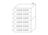
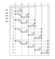
- FIG. 6 is a first diagram showing an example of the internal wiring of the casing of the circuit breaker according to Example 1 of the embodiment of the present invention.
- the housing 20 shown in FIG. 5 has six slots 30 into which six isolation units 10 can be inserted.
- the interrupting units 10 inserted into each slot 30 are wired in advance so as to be connected between different points.
- the circuit including the first slot 30 functions as a two-way circuit 801.
- the circuit breaker including the circuit breaker 10 and the housing 20 inserted into the first slot 30 functions as a two-way circuit breaker 901.
- a circuit including the first to third slots 30 functions as a three-way circuit 802.
- the circuit breaker including the circuit breaker 10 and the housing 20 inserted into the first to third slots 30 functions as a three-way circuit breaker 902.
- a circuit including the first to sixth slots 30 functions as a four-way circuit 803.
- the circuit breaker including the circuit breaker 10 and the housing 20 inserted into the six slots 30 from the first to the sixth slot functions as a four-way circuit breaker 903.
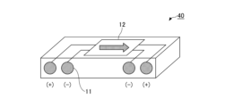
- FIG. 7 is a diagram showing an example of a conventional shut-off unit.
- a conventionally commonly used shutoff unit 40 includes four connectors 11 and one internal circuit 12.
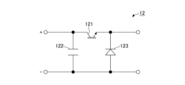
- FIG. 8 is a diagram showing an example of the internal circuit of a conventional cutoff unit.
- the internal circuit 12 includes, for example, a switch 121, a capacitor 122, and a diode 123.
- the capacitor 122 functions to suppress voltage fluctuations when the circuit is interrupted for a short time.
- the diode 123 functions to suppress overvoltage when the circuit is interrupted for a long time.
- Such an internal circuit 12 can cut off current in only one direction.
- FIG. 9 is a diagram showing an example of a cutoff unit according to Example 1 of the embodiment of the present invention.
- the cutoff unit 10 according to this embodiment includes four connectors 11 and two internal circuits 12.
- the internal circuit 12 may be the circuit shown in FIG.
- the internal circuits 12 are connected in series in opposite directions. Thereby, the cutoff unit 10 can cut off current in two directions (bidirectional).
- a circuit breaker that branches in multiple directions is configured by combining the above-described circuit breaker unit 10 and the housing 20. Although a circuit breaker with four directions or less has been described, a circuit breaker extending in five directions or more can be similarly configured.
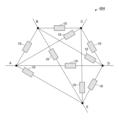
- FIG. 10 is a diagram showing a circuit breaker branching in five directions.
- the five-way circuit breaker 904 includes ten interrupting units 10. Each cutoff unit 10 is connected between AB, between AC, between AD, between AE, between BC, between BD, between BE, between CD, between CE, and between DE. Each cutoff unit 10 can cut off current in two directions between two connected points. Thereby, the five-way circuit breaker 904 can interrupt currents in all combinations of the five points A, B, C, D, and E.
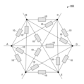
- FIG. 11 is a diagram showing a circuit breaker branching in six directions.
- the six-way circuit breaker 905 includes 15 disconnection units 10.
- Each of the cutoff units 10 has a cutoff between AB, AC, AD, AE, AF, BC, BD, BE, BF, CD, CE, CF, DE, DF, and EF. are connected in between.
- Each cutoff unit 10 can cut off current in two directions between two connected points. Thereby, the six-way circuit breaker 905 can interrupt currents in all combinations of directions at the six points A, B, C, D, E, and F.
- FIG. 12 is a second diagram showing an example of the internal wiring of the case of the circuit breaker according to Example 1 of the embodiment of the present invention.
- the housing 20 has 15 slots 30 into which 15 cutoff units 10 can be inserted.
- the interrupting units 10 inserted into each slot 30 are wired in advance so as to be connected between different points.
- the circuit including the first slot 30 functions as a two-way circuit 801.
- the circuit breaker including the circuit breaker 10 and the housing 20 inserted into the first slot 30 functions as a two-way circuit breaker 901.
- a circuit including the first to third slots 30 functions as a three-way circuit 802.
- the circuit breaker including the circuit breaker 10 and the housing 20 inserted into the first to third slots 30 functions as a three-way circuit breaker 902.
- a circuit including the first to sixth slots 30 functions as a four-way circuit 803.
- the circuit breaker including the circuit breaker 10 and the housing 20 inserted into the six slots 30 from the first to the sixth slot functions as a four-way circuit breaker 903.
- a circuit including the first to tenth slots 30 functions as a five-way circuit 804.
- the circuit breaker including the circuit breaker 10 and the housing 20 inserted into the ten slots 30 from the first to the tenth slot functions as a five-way circuit breaker 904.
- a circuit including the first to fifteenth slots 30 functions as a six-way circuit 805.
- the circuit breaker including the circuit breaker 10 and the housing 20 inserted into the fifteen slots 30 from the first to the fifteenth slot functions as a six-way circuit breaker 905.
- FIG. 13 is a diagram showing the appearance of a casing of a circuit breaker according to a modification of Example 1 of the embodiment of the present invention.
- the housing 21 shown in FIG. 13 includes six slots 30 for realizing a four-way circuit breaker 903, and further includes a seventh slot for inserting a capacitor box and an eight slot for inserting a fan. and a second slot.
- the capacitor box may be, for example, a capacitor that suppresses arcing during interruption, a transient voltage countermeasure circuit, an overcurrent countermeasure circuit, or the like.
- the fan may be a cooler for cooling heat generated due to conduction loss at the DC cutoff contact.
- the housing 21 has four connectors A to D facing outward. Each connector is connected to various power supplies, loads, etc. in the power supply network.
- the shutoff unit 10 capable of shutting off in two directions is combined with the external casing 20 having a plurality of slots.
- the structure of the circuit breaker that branches in the direction can be simplified. For example, since one type of interrupting unit 10 can constitute a circuit breaker that branches in multiple types of directions, the interrupting unit 10 can be mass-produced.
- interrupting unit 10 interrupts current in two directions (bidirectional)
- a interrupting unit that interrupts current in one direction may be used.
- one type (or several types) of slot-type circuit breakers can be used in two directions or three directions. It is possible to configure multi-directional branch points such as directional, four-directional, five-directional, six-directional, etc.
- Power routing is also possible by controlling ON/OFF of the circuit breaker according to this embodiment for each port.
- a power supply system including multidirectional branch points as shown in Fig. 1 secures the power supply route by locking the one-to-one or n-to-n power supply route for a certain period of time.
- the circuit breaker has an interlock function that prevents it from intersecting with another power supply route while power is being supplied, and if the power supply route branches during power supply, the circuit breaker is equipped with OCP (Over Current Protection) to provide a protective coordination function. )
- OCP Over Current Protection
- FIG. 14 is a diagram showing an example of a conventional bidirectional power feeding system.
- a power supply system 920 for bidirectionally supplying power between base A and base B includes a power supply converter at each base.
- Base A is an example of a building that serves as a base, such as a communications building.
- Base B is, for example, a shelter.
- Each converter communicates (handshakes) with each other before exchanging power.
- power can be exchanged in both directions on a one-to-one basis between bases.
- FIG. 15 is a sequence diagram showing an example of a handshake flow in a conventional bidirectional power supply system.
- the converter located at base A is referred to as a first converter 931, and the converter located at base B is referred to as a second converter 932.
- first converter 931 is transmitting power (power transmission mode) and the second converter 932 is receiving power (power reception mode).
- This state is referred to as state ⁇ .
- a state in which the first converter 931 is receiving power (power receiving mode) and the second converter 932 is transmitting power (power transmitting mode) is defined as state ⁇ .
- FIG. 15 shows the flow of transition from state ⁇ to state ⁇ .
- the first converter 931 stops power transmission (step S101).
- the first converter 931 notifies the second converter 932 of the stoppage (step S102).
- the second converter 932 Upon receiving the stop notification, the second converter 932 notifies the first converter 931 to start power transmission (step S103). Upon receiving the notification of the start of power transmission, first converter 931 changes the operation mode to power reception mode (step S104).
- the first converter 931 notifies the second converter 932 of the change in the operating mode (step S105).
- the second converter 932 receives the notification of the change in the operation mode, it changes the operation mode to the power transmission mode (step S106).
- the above procedure completes the transition from state ⁇ to state ⁇ .
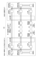
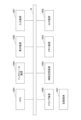
- FIG. 16 is a diagram showing the configuration of a power supply system according to Example 2 of the embodiment of the present invention.
- a control device is installed at each site to control the converter at each site and the circuit breakers arranged in the power supply network.
- a converter 50, a control device 60, and an insulation monitoring device 70 are installed.
- the control device 60 includes a control section 61, a storage section 62, a determination section 63, a monitoring section 64, a display section 65, and a communication section 66.
- Control unit 61 controls converter 50 and circuit breaker 22 .
- the storage unit 62 stores information such as threshold values necessary for control.
- the determination unit 63 performs determination processing for determining the operation mode of each converter, determining the power supply route, etc.
- the monitoring unit 64 monitors the operation mode of power supply by the converter 50 based on detection results from an ammeter, a voltmeter, and the like.
- the display unit 65 displays control details.
- the communication unit 66 communicates with the database 80 and the control device 60 (installed at another base (base B, etc.)).
- the database 80 stores learned models generated through analysis, learning, etc. Note that the database 80 may be of a centralized type or a distributed type.
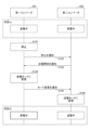
- FIG. 17 is a flowchart illustrating an example of the flow of control processing according to Example 2 of the embodiment of the present invention.
- the control device 60 acquires basic data (step S201).
- the basic data may be, for example, GB operating time, X capacitor capacity, cable impedance, fuse blowing characteristics, power network configuration, slot type circuit breaker information, currently locked route information, etc.
- control device 60 acquires control data (step S202).
- the control data may be specifications of a converter capable of transmitting power, specifications of a converter capable of receiving power, PV power, SoC of a storage battery, load capacity, weather information, weather forecast information, etc. Note that the control device 60 may accept input of control data.
- the determination unit 63 determines the operation mode of each converter (step S203). Specifically, when the converter 50 of the base A is transmitting power to the base B, the determination unit 63 controls the converter 50 of the base B to be in the power receiving mode and not to be in the power transmitting mode.
- the monitoring unit 64 detects that power is being transmitted using a control signal, a detector, etc.
- the determination unit 63 controls the converter 50 at base A to be in the power reception mode and not to be in the power transmission mode.
- the determination unit 63 determines a power feeding route (step S204). Details of the method for determining the power supply route will be described later.
- the communication unit 66 communicates between the control devices (step S205).
- the control device 60 may execute the handshake procedure shown in FIG. 15.
- Control unit 61 then transmits control signals to converter 50 and circuit breaker 22, respectively (step S206).
- control unit 61 locks the power supply path and sets protection cooperation (step S207).
- a method for locking the power supply path and setting protection coordination will be described later.
- Control unit 61 transmits control signals to converter 50 and circuit breaker 22, respectively, according to the settings (step S208). Upon detecting the elapse of a certain period of time or the pressing of the emergency stop signal, the control unit 61 unlocks the power supply path and resets protection coordination (step S209).
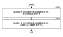
- FIG. 18 is a flowchart illustrating an example of the flow of the power supply route determination process according to Example 2 of the embodiment of the present invention.
- the determination unit 63 selects the shortest route among the available power supply routes connecting the bases (step S301). Next, the determination unit 63 selects the second shortest route among the available power supply routes connecting the bases (step S302).
- FIG. 18 shows a configuration example of one-to-one power feeding
- the determination unit 63 may also set a current threshold for n-to-n power feeding and execute a similar interlock.
- the interlock condition may be that the sum of the transmitted power and the sum of the received power (+power transmission loss) match.
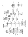
- FIG. 19 is a first diagram for explaining a method for determining a power feeding route according to Example 2 of the embodiment of the present invention.
- FIG. 19 shows a method for determining a power supply route in the case of one-to-one power supply.
- the determination unit 63 determines the shortest route and the second shortest route. By determining a plurality of power feeding paths, the impedance of the power feeding path can be reduced and wiring loss can be reduced.
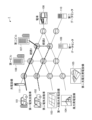
- FIG. 20 is a second diagram for explaining a method for determining a power feeding route according to Example 2 of the embodiment of the present invention.
- FIG. 20 shows a method for determining the power supply route in the case of one-to-two power supply.
- the determination unit 63 determines, for example, a route for supplying power from the second building 107 to the first electric vehicle 101 (route 1) and the second electric vehicle 102 (route 2). Because there are branches in the feeder line, it is necessary to limit the maximum current before and after the branch for protection coordination at the branch point.
- FIG. 21 is a diagram for explaining a method of locking a power supply path and setting protection coordination according to Example 2 of the embodiment of the present invention.
- the control unit 61 turns on all circuit breakers 22 installed in the power supply path connecting the converter 50 in the power transmission mode and the converter 50 in the power reception mode. Further, the control unit 61 fixes all circuit breakers 22 installed in paths intersecting the power feeding path to OFF (interlock). Further, the control unit 61 recognizes that the other circuit breakers 22 can be used on other routes. In this way, the control unit 61 locks the power supply path.
- control unit 61 sets the OCP of the circuit breaker 22, such as a fuse, a molded circuit breaker, etc., according to the number of branching paths. In this way, the control unit 61 executes the protection cooperation setting. This eliminates the need for the cost, time, etc. of constructing a new route.
- the control device 60 can be realized, for example, by causing a computer to execute a program that describes the processing contents described in this embodiment.
- this "computer” may be a physical machine or a virtual machine on a cloud.
- the "hardware” described here is virtual hardware.
- the above program can be recorded on a computer-readable recording medium (portable memory, etc.), and can be stored or distributed. It is also possible to provide the above program through a network such as the Internet or e-mail.
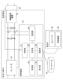
- FIG. 22 is a diagram showing an example of the hardware configuration of the computer.
- the computer in FIG. 22 includes a drive device 1000, an auxiliary storage device 1002, a memory device 1003, a CPU 1004, an interface device 1005, a display device 1006, an input device 1007, an output device 1008, etc., which are interconnected by a bus B.
- a program that realizes processing on the computer is provided, for example, on a recording medium 1001 such as a CD-ROM or a memory card.
- a recording medium 1001 such as a CD-ROM or a memory card.
- the program is installed from the recording medium 1001 to the auxiliary storage device 1002 via the drive device 1000.
- the program does not necessarily need to be installed from the recording medium 1001, and may be downloaded from another computer via a network.
- the auxiliary storage device 1002 stores installed programs as well as necessary files, data, and the like.
- the memory device 1003 reads and stores the program from the auxiliary storage device 1002 when there is an instruction to start the program.
- the CPU 1004 implements functions related to the device according to programs stored in the memory device 1003.
- the interface device 1005 is used as an interface for connecting to a network.
- a display device 1006 displays a GUI (Graphical User Interface) or the like based on a program.
- the input device 1007 is composed of a keyboard, a mouse, buttons, a touch panel, or the like, and is used to input various operation instructions.
- An output device 1008 outputs the calculation result.
- the computer may include a GPU (Graphics Processing Unit) or a TPU (Tensor Processing Unit) instead of the CPU 1004, or may include a GPU or a TPU in addition to the CPU 1004. In that case, the processing may be divided and executed, for example, the GPU or TPU executes processing that requires special calculations, and the CPU 1004 executes other processing.
- control device 60 realizes the interlock function and the protection cooperation function by locking the power supply path and setting the protection cooperation.
- the interlock allows cables (routes) related to power supply and reception to be separated from other power supply routes, creating an independent and safe route. Also, changing the route does not require physical additions or renovations.
- Example 3 In this embodiment, an example will be described in which the integration of branch cutoff circuits is realized.
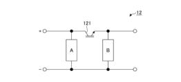
- FIG. 23 is a diagram for explaining a conventional cutoff circuit.
- Internal circuit 12 includes switch 121 and A and B.
- a of FIG. 23 a capacitor or the like is used to suppress voltage fluctuations when the circuit is interrupted for a short time.
- B of FIG. 23 a capacitor, a diode, or the like is used to suppress overvoltage when the circuit is interrupted for a long time.
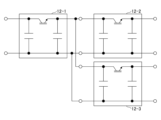
- FIG. 24 is a diagram for explaining a conventional branch breaker circuit.
- branching has been achieved by arranging the circuits in FIG. 23 as shown in internal circuits 12-1 to 12-3 in FIG. That is, conventionally, the branch breaker circuit has not been considered as an integrated device.
- FIG. 25 is a diagram showing an example of a branch cutoff circuit according to Example 3 of the embodiment of the present invention.
- the second embodiment by cooperatively controlling the operation of each circuit breaker, there is no need to connect a load device or the like on the connection point side of each circuit breaker, and no capacitors, diodes, etc. are required. Therefore, we will delete them and create an integrated configuration (systemization).
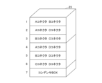
- FIG. 26 is a diagram showing an example of a case of a circuit breaker according to Example 3 of the embodiment of the present invention.
- the housing 23 has a capacitor box in the seventh slot.
- the slot may be replaced depending on the conditions (rated current, voltage suppression level, etc.). Also, capacitors that tend to deteriorate may be slotted and replaced.
- FIG. 27 is a diagram showing an example of a circuit breaker circuit according to Example 3 of the embodiment of the present invention.
- a capacitor 90 By mounting a capacitor 90 on the output side of each port as in the example of the double line diagram shown in FIG. 27, the branch cutoff circuit shown in FIG. 25 can be realized.
- the capacitors, diodes, etc. on the connection point side of each circuit breaker are removed to create an integrated configuration. This reduces the cost and size of the circuit breaker. Therefore, it is possible to realize the integration of branch cutoff circuits that can accommodate complex networks.
- the casing includes ten or more slots into which the cutoff units are inserted, and circuits prewired to be connected between five or more different points depending on the slots into which the cutoff units are inserted.
- the circuit breaker according to item 1 or 2.
- (Section 5) a interrupting unit for interrupting current in two directions; By a circuit breaker comprising a housing including a plurality of slots into which the breaking units are inserted, and circuits that are pre-wired to be connected between different points depending on the slots in which the breaking units are inserted, Blocks current in multiple directions, Blocking method.
Landscapes
- Engineering & Computer Science (AREA)
- Power Engineering (AREA)
- Remote Monitoring And Control Of Power-Distribution Networks (AREA)
- Emergency Protection Circuit Devices (AREA)
Abstract
Description
本実施の形態に係る給電システムは、屋外において使用される場合など、様々な電源(太陽光発電(PV:Photovoltaics)、風力発電等)や負荷(EV(Electric Vehicle)、蓄電池等)が双方向に接続される場合を想定している。そのため、接続点は二方向だけでなく、三方向、四方向等があり、保護のための遮断器を分岐の数に合わせて個別にカスタマイズする必要がある。
本実施例では、二方向の遮断が可能な遮断ユニットを、複数のスロットを有する外部の筐体と組み合わせることで、遮断器の拡張を可能にする。具体的には、遮断ユニットを挿入するスロットの位置を変えることで、三方向、四方向等の多方向の分岐を可能にする例について説明する。
本実施例では、図1に示すような多方向の分岐点を含む給電システムが、安全性を確保するため、1対1またはn対nの給電経路を一定時間ロックして給電経路を確保し、給電中は別の給電経路と交わらないようなインターロック機能を有し、給電中の給電経路が分岐する場合、保護協調機能となるように、遮断器にOCP(過電流保護:Over Current Protection)の電流量を設定する制御方法について説明する。
本実施例では、分岐遮断回路の一体化を実現させる例について説明する。
本明細書には、少なくとも下記の各項に記載した遮断器および遮断方法が記載されている。
(第1項)
二方向の電流を遮断するための遮断ユニットと、
前記遮断ユニットを挿入する複数のスロットと、前記遮断ユニットの挿入されたスロットに応じてそれぞれ異なる点間に接続されるようにあらかじめ配線された回路とを含む筐体と、を備える、
遮断器。
(第2項)
前記遮断ユニットは、一方向の電流を遮断するための回路を逆向きに直列に接続されている、
第1項に記載の遮断器。
(第3項)
前記筐体は、前記遮断ユニットを挿入する6つのスロットと、前記遮断ユニットの挿入されたスロットに応じてそれぞれ異なる4点間に接続されるようにあらかじめ配線された回路とを含む、
第1項または第2項に記載の遮断器。
(第4項)
前記筐体は、前記遮断ユニットを挿入する10個以上のスロットと、前記遮断ユニットの挿入されたスロットに応じてそれぞれ異なる5点以上の間に接続されるようにあらかじめ配線された回路とを含む、
第1項または第2項に記載の遮断器。
(第5項)
二方向の電流を遮断するための遮断ユニットと、
前記遮断ユニットを挿入する複数のスロットと、前記遮断ユニットの挿入されたスロットに応じてそれぞれ異なる点間に接続されるようにあらかじめ配線された回路とを含む筐体と、を備える遮断器によって、多方向の電流を遮断する、
遮断方法。
10 遮断ユニット
11 コネクタ
12 内部回路
20,21 筐体
22 遮断器
30 スロット
40 遮断ユニット
50 コンバータ
60 制御装置
61 制御部
62 記憶部
63 判定部
64 監視部
65 表示部
66 通信部
70 絶縁監視装置
80 データベース
101 第一電気自動車
102 第二電気自動車
103 第一太陽光発電設備
104 風力発電設備
105 第二太陽光発電設備
106 第一ビル
107 第二ビル
108 電車
109 第一データセンタ
110 第二データセンタ
111 充電設備
121 スイッチ
122 コンデンサ
123 ダイオード
901 二方向遮断器
902 三方向遮断器
903 四方向遮断器
904 五方向遮断器
905 六方向遮断器
1000 ドライブ装置
1001 記録媒体
1002 補助記憶装置
1003 メモリ装置
1004 CPU
1005 インタフェース装置
1006 表示装置
1007 入力装置
1008 出力装置
Claims (5)
- 二方向の電流を遮断するための遮断ユニットと、
前記遮断ユニットを挿入する複数のスロットと、前記遮断ユニットの挿入されたスロットに応じてそれぞれ異なる点間に接続されるようにあらかじめ配線された回路とを含む筐体と、を備える、
遮断器。 - 前記遮断ユニットは、一方向の電流を遮断するための回路を逆向きに直列に接続されている、
請求項1に記載の遮断器。 - 前記筐体は、前記遮断ユニットを挿入する6つのスロットと、前記遮断ユニットの挿入されたスロットに応じてそれぞれ異なる4点間に接続されるようにあらかじめ配線された回路とを含む、
請求項1または2に記載の遮断器。 - 前記筐体は、前記遮断ユニットを挿入する10個以上のスロットと、前記遮断ユニットの挿入されたスロットに応じてそれぞれ異なる5点以上の間に接続されるようにあらかじめ配線された回路とを含む、
請求項1または2に記載の遮断器。 - 二方向の電流を遮断するための遮断ユニットと、
前記遮断ユニットを挿入する複数のスロットと、前記遮断ユニットの挿入されたスロットに応じてそれぞれ異なる点間に接続されるようにあらかじめ配線された回路とを含む筐体と、を備える遮断器によって、多方向の電流を遮断する、
遮断方法。
Priority Applications (3)
| Application Number | Priority Date | Filing Date | Title |
|---|---|---|---|
| US18/854,304 US20250246387A1 (en) | 2022-04-11 | 2022-04-11 | Circuit breaker and interruption method |
| JP2024515189A JP7852708B2 (ja) | 2022-04-11 | 2022-04-11 | 遮断器および遮断方法 |
| PCT/JP2022/017505 WO2023199378A1 (ja) | 2022-04-11 | 2022-04-11 | 遮断器および遮断方法 |
Applications Claiming Priority (1)
| Application Number | Priority Date | Filing Date | Title |
|---|---|---|---|
| PCT/JP2022/017505 WO2023199378A1 (ja) | 2022-04-11 | 2022-04-11 | 遮断器および遮断方法 |
Publications (1)
| Publication Number | Publication Date |
|---|---|
| WO2023199378A1 true WO2023199378A1 (ja) | 2023-10-19 |
Family
ID=88329213
Family Applications (1)
| Application Number | Title | Priority Date | Filing Date |
|---|---|---|---|
| PCT/JP2022/017505 Ceased WO2023199378A1 (ja) | 2022-04-11 | 2022-04-11 | 遮断器および遮断方法 |
Country Status (3)
| Country | Link |
|---|---|
| US (1) | US20250246387A1 (ja) |
| JP (1) | JP7852708B2 (ja) |
| WO (1) | WO2023199378A1 (ja) |
Citations (3)
| Publication number | Priority date | Publication date | Assignee | Title |
|---|---|---|---|---|
| JPH0374106U (ja) * | 1989-11-22 | 1991-07-25 | ||
| JP3113266U (ja) * | 2005-06-03 | 2005-09-02 | 株式会社昭電 | ユニット式分電盤 |
| WO2020021656A1 (ja) * | 2018-07-25 | 2020-01-30 | 三菱電機株式会社 | 半導体遮断器及び遮断装置 |
-
2022
- 2022-04-11 US US18/854,304 patent/US20250246387A1/en active Pending
- 2022-04-11 WO PCT/JP2022/017505 patent/WO2023199378A1/ja not_active Ceased
- 2022-04-11 JP JP2024515189A patent/JP7852708B2/ja active Active
Patent Citations (3)
| Publication number | Priority date | Publication date | Assignee | Title |
|---|---|---|---|---|
| JPH0374106U (ja) * | 1989-11-22 | 1991-07-25 | ||
| JP3113266U (ja) * | 2005-06-03 | 2005-09-02 | 株式会社昭電 | ユニット式分電盤 |
| WO2020021656A1 (ja) * | 2018-07-25 | 2020-01-30 | 三菱電機株式会社 | 半導体遮断器及び遮断装置 |
Also Published As
| Publication number | Publication date |
|---|---|
| US20250246387A1 (en) | 2025-07-31 |
| JP7852708B2 (ja) | 2026-04-28 |
| JPWO2023199378A1 (ja) | 2023-10-19 |
Similar Documents
| Publication | Publication Date | Title |
|---|---|---|
| ES2702988T3 (es) | Procedimientos y sistemas de operación de un sistema de generación de energía | |
| US20170214225A1 (en) | Interconnect and metering for renewables, storage and additional loads with electronically controlled disconnect capability for increased functionality | |
| US20120019203A1 (en) | Energy storage and vehicle charging system and method of operation | |
| KR101571213B1 (ko) | 고장처리장치를 구비하는 마이크로그리드 시스템 및 그 동작 방법 | |
| WO2015134851A1 (en) | Dc power server for a dc microgrid | |
| CN105870893B (zh) | 微网群的保护配置方法 | |
| Prasai et al. | Protection of meshed microgrids with communication overlay | |
| US10122291B2 (en) | Redundant control device and method of HVDC system | |
| GB2523535A (en) | Breaker circuit configurations for multi-terminal DC systems | |
| JP7798182B2 (ja) | 制御装置、給電システム、制御方法およびプログラム | |
| Chandraratne et al. | Smart grid protection through self-healing | |
| CN104953699A (zh) | 微电网系统无缝切换控制方法 | |
| WO2023199378A1 (ja) | 遮断器および遮断方法 | |
| JP6141227B2 (ja) | パワーコンディショナ | |
| WO2023199377A1 (ja) | 遮断器および遮断方法 | |
| Haider et al. | Protection coordination using superconducting fault current limiters in microgrids | |
| CN113809766B (zh) | 一种多母线储能系统及其控制方法 | |
| Larruskain et al. | Requirements for fault protection in HVDC grids | |
| US20230275405A1 (en) | Switching system | |
| Štefko et al. | Design of a protection system for distributed energy sources in distribution grids | |
| CN212695892U (zh) | 一种双开关电源热备供电组 | |
| Chanaa et al. | Islanding Detection Method of a Photovoltaic Installation Destined to Power a RLC Load and Integrated to LV Network. | |
| JP2018074643A (ja) | 停電補償装置付き分電盤 | |
| Bello et al. | Lessons learned on protection coordination considerations within inverter-based microgrids | |
| US12549028B2 (en) | Microinverter-integrated battery paralleling devices |
Legal Events
| Date | Code | Title | Description |
|---|---|---|---|
| 121 | Ep: the epo has been informed by wipo that ep was designated in this application |
Ref document number: 22937358 Country of ref document: EP Kind code of ref document: A1 |
|
| ENP | Entry into the national phase |
Ref document number: 2024515189 Country of ref document: JP Kind code of ref document: A |
|
| WWE | Wipo information: entry into national phase |
Ref document number: 18854304 Country of ref document: US |
|
| NENP | Non-entry into the national phase |
Ref country code: DE |
|
| 122 | Ep: pct application non-entry in european phase |
Ref document number: 22937358 Country of ref document: EP Kind code of ref document: A1 |
|
| WWP | Wipo information: published in national office |
Ref document number: 18854304 Country of ref document: US |