WO2023199552A1 - Dispositif et procédé de détection - Google Patents
Dispositif et procédé de détection Download PDFInfo
- Publication number
- WO2023199552A1 WO2023199552A1 PCT/JP2022/046331 JP2022046331W WO2023199552A1 WO 2023199552 A1 WO2023199552 A1 WO 2023199552A1 JP 2022046331 W JP2022046331 W JP 2022046331W WO 2023199552 A1 WO2023199552 A1 WO 2023199552A1
- Authority
- WO
- WIPO (PCT)
- Prior art keywords
- message
- detection
- reception interval
- messages
- burst
- Prior art date
- Legal status (The legal status is an assumption and is not a legal conclusion. Google has not performed a legal analysis and makes no representation as to the accuracy of the status listed.)
- Ceased
Links
Images




Classifications
-
- H—ELECTRICITY
- H04—ELECTRIC COMMUNICATION TECHNIQUE
- H04L—TRANSMISSION OF DIGITAL INFORMATION, e.g. TELEGRAPHIC COMMUNICATION
- H04L43/00—Arrangements for monitoring or testing data switching networks
- H04L43/08—Monitoring or testing based on specific metrics, e.g. QoS, energy consumption or environmental parameters
- H04L43/0852—Delays
-
- H—ELECTRICITY
- H04—ELECTRIC COMMUNICATION TECHNIQUE
- H04L—TRANSMISSION OF DIGITAL INFORMATION, e.g. TELEGRAPHIC COMMUNICATION
- H04L41/00—Arrangements for maintenance, administration or management of data switching networks, e.g. of packet switching networks
- H04L41/06—Management of faults, events, alarms or notifications
- H04L41/0631—Management of faults, events, alarms or notifications using root cause analysis; using analysis of correlation between notifications, alarms or events based on decision criteria, e.g. hierarchy, tree or time analysis
-
- H—ELECTRICITY
- H04—ELECTRIC COMMUNICATION TECHNIQUE
- H04L—TRANSMISSION OF DIGITAL INFORMATION, e.g. TELEGRAPHIC COMMUNICATION
- H04L43/00—Arrangements for monitoring or testing data switching networks
- H04L43/16—Threshold monitoring
Definitions
- the present disclosure relates to a sensing device and a sensing method.
- This application claims priority based on Japanese Patent Application No. 2022-65792 filed on April 12, 2022, and the entire disclosure thereof is incorporated herein.
- Patent Document 1 International Publication No. 2021/111685 discloses the following detection device. That is, the detection device is a detection device that detects fraudulent messages in an in-vehicle network, and includes an acquisition unit that acquires a target distribution that is a distribution of reception intervals of periodic messages transmitted in the in-vehicle network; an extraction unit that extracts a part of the target distribution according to a predetermined standard, and a detection unit that performs a detection process to detect the fraudulent message based on the part of the target distribution extracted by the extraction unit. Be prepared.
- the detection device is a detection device that detects fraudulent messages in an in-vehicle network, and includes an acquisition unit that acquires a target distribution that is a distribution of reception intervals of periodic messages transmitted in the in-vehicle network; an extraction unit that extracts a part of the target distribution according to a predetermined standard, and a detection unit that performs a detection process to detect the fraudulent message based on the part of the target distribution extracted by the extraction unit. Be prepared.
- a detection device of the present disclosure is a detection device that detects an abnormality in a network in which a plurality of target messages including periodic messages transmitted and received at a predetermined transmission cycle are transmitted and received, and the detection device calculates a reception interval of the target messages.
- a detection unit that performs a detection process to detect an abnormality in the network based on the reception interval calculated by the calculation unit, and the target message whose reception interval is greater than the transmission cycle by a predetermined value or more.
- a counting unit that counts a plurality of burst messages including a delayed message and one or more target messages received following the delayed message and whose reception interval is equal to or less than a predetermined value; , it is determined whether or not to perform the detection process based on the reception interval for at least one of the plurality of burst messages, based on the count value by the count unit.
- the detection method of the present disclosure is a detection method for a detection device that detects an abnormality in a network in which a plurality of target messages including periodic messages transmitted and received at a predetermined transmission cycle are transmitted and received, a step of performing detection processing to detect an abnormality in the network based on the calculated reception interval; and a delayed message that is the target message in which the reception interval is larger than the transmission cycle by a predetermined value or more;
- the step of performing the detection process includes the step of counting a plurality of burst messages including one or more of the target messages in which the reception interval is equal to or less than a predetermined value and which are received following the delayed message, and the step of performing the detection processing includes: Based on the count value of the plurality of burst messages, it is determined whether or not to perform the detection process based on the reception interval for at least one of the plurality of burst messages.
- One aspect of the present disclosure can be realized not only as a detection device including such a characteristic processing unit, but also as a program for causing a computer to execute such characteristic processing steps, or as a detection device including such a characteristic processing unit. It can be realized as a semiconductor integrated circuit that realizes part or all of the above, or it can be realized as a system including a detection device.
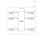
- FIG. 1 is a diagram showing the configuration of a communication system according to an embodiment of the present disclosure.
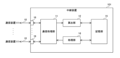
- FIG. 2 is a diagram showing the configuration of a relay device according to an embodiment of the present disclosure.
- FIG. 3 is a diagram illustrating an example of a distribution of target messages and reception times received by a relay device according to an embodiment of the present disclosure.
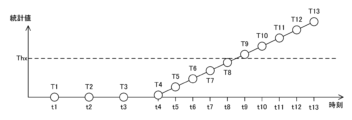
- FIG. 4 is a diagram illustrating an example of statistical values used for detection processing in the relay device according to the embodiment of the present disclosure.
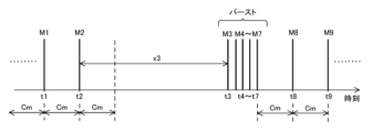
- FIG. 5 is a diagram illustrating another example of the distribution of target messages and reception times received by the relay device according to the embodiment of the present disclosure.
- FIG. 6 is a diagram illustrating an example of statistical values used for detection processing in a relay device according to a comparative example of the embodiment of the present disclosure.
- FIG. 1 is a diagram showing the configuration of a communication system according to an embodiment of the present disclosure.
- FIG. 2 is a diagram showing the configuration of a relay device according to an embodiment of the present disclosure.
- FIG. 3
- FIG. 7 is a diagram illustrating an example of a reception time of a target message received by a relay device according to an embodiment of the present disclosure.
- FIG. 8 is a diagram illustrating another example of the reception time of the target message received by the relay device according to the embodiment of the present disclosure.
- FIG. 9 is a diagram illustrating an example of a reception time of a target message received by a relay device according to an embodiment of the present disclosure.
- FIG. 10 is a diagram illustrating another example of the reception time of the target message received by the relay device according to the embodiment of the present disclosure.
- FIG. 11 is a diagram illustrating an example of a reception time of a target message received by a relay device according to an embodiment of the present disclosure.
- FIG. 12 is a diagram illustrating an example of a correspondence table stored in a storage unit in a relay device according to an embodiment of the present disclosure.
- FIG. 13 is a flowchart defining an example of an operation procedure when the relay device according to the embodiment of the present disclosure performs detection processing.
- FIG. 14 is a flowchart defining an example of an operation procedure when the relay device according to the embodiment of the present disclosure performs a process of counting burst messages.
- FIG. 15 is a diagram illustrating an example of a network connection topology according to an embodiment of the present disclosure.
- FIG. 16 is a diagram illustrating another example of the correspondence table stored in the storage unit in the relay device according to the embodiment of the present disclosure.
- the present disclosure has been made to solve the above-mentioned problems, and its purpose is to provide a detection device and a detection method that can more accurately detect abnormalities in a network.
- a detection device is a detection device that detects an abnormality in a network in which a plurality of target messages including periodic messages that are transmitted and received at a predetermined transmission cycle is transmitted and received.
- a calculation unit that calculates a message reception interval; a detection unit that performs a detection process to detect an abnormality in the network based on the reception interval calculated by the calculation unit;
- a counting unit that counts a plurality of burst messages including a delayed message that is the target message that is larger than a value, and one or more target messages that are received following the delayed message and whose reception interval is equal to or less than a predetermined value. and whether or not the detection unit performs the detection process based on the reception interval for at least one of the plurality of burst messages based on the count value by the count unit. Determine.
- the configuration that determines whether or not to perform detection processing based on the reception interval of burst messages based on the count value of burst messages allows multiple It is possible to decide whether or not to target multiple burst messages for detection processing depending on the probability that the burst messages include fraudulent target messages, so for example, if a burst phenomenon occurs This makes it possible to prevent false positives caused by false positives and to prevent fraudulent messages included in multiple burst messages from being overlooked. Therefore, abnormalities in the network can be detected more accurately.
- the detection unit when the count value is less than or equal to a threshold value, the detection unit performs the detection based on the reception interval of at least one of the burst messages among the plurality of burst messages. No processing is required.
- the detection unit may perform the detection process based on the reception interval of the plurality of burst messages when the count value is larger than the threshold. good.
- detection processing can be performed based on the reception interval of multiple burst messages, without excluding multiple burst messages that may include invalid target messages from detection processing targets. This makes it possible to prevent unauthorized messages from being overlooked.
- the detection unit may determine the threshold according to the reception interval of the target message, which is the delayed message.
- the detection unit calculates a detection index that increases or decreases depending on the relationship between the reception interval and reference information regarding the reception interval, and The detection processing is performed based on an index, and when the count value is less than or equal to the threshold, the detection unit detects the detection index for at least one of the burst messages among the plurality of burst messages.
- a configuration in which no calculation is performed may also be used.
- the counting unit ends counting if the next target message is not received within a predetermined time from the reception time of the target message that is the burst message.
- the detection section may suspend the detection processing until the counting section finishes counting, and restart the detection processing after the counting section finishes counting.
- counting of burst messages can be ended with the end of a burst phenomenon, and detection processing can be restarted at a more appropriate timing.
- a detection method is a detection method in a detection device that detects an abnormality in a network where a plurality of target messages including periodic messages that are transmitted and received at a predetermined transmission cycle are transmitted and received. , a step of calculating a reception interval of the target message; a step of performing a detection process of detecting an abnormality in the network based on the calculated reception interval; counting a plurality of burst messages including a delayed message that is a target message, and one or more target messages received following the delayed message and whose reception interval is equal to or less than a predetermined value; In the step of performing the detection process, based on the count value of the plurality of burst messages, the detection process is performed on at least one of the plurality of burst messages based on the reception interval. Decide whether
- FIG. 1 is a diagram showing the configuration of a communication system according to an embodiment of the present disclosure.
- communication system 301 includes a relay device 101 and a plurality of communication devices 111.
- Communication system 301 is mounted on a vehicle, for example.
- the communication device 111 is, for example, an in-vehicle ECU (Electronic Control Unit).
- the communication system 301 may include a relay device other than the relay device 101 (not shown).
- the relay device 101 and the communication device 111 constitute a network 201. More specifically, relay device 101 and communication device 111 are connected to each other via transmission line 10.
- the communication system 301 may have a configuration in which the relay device 101 is connected one-to-one to the communication device 111 via the line-type transmission line 10 as shown in FIG.
- the device may be connected to a communication device 111 via a transmission line 10, or may be connected to a plurality of communication devices 111 in a one-to-many manner via a bus-type transmission line 10. It's okay.
- the transmission line 10 is, for example, CAN (Controller Area Network) (registered trademark), FlexRay (registered trademark), MOST (Media Oriented Systems Transport) (registered trademark), Ethernet (registered trademark), and LIN (Lo cal Interconnect Network) etc.
- CAN Controller Area Network
- FlexRay registered trademark
- MOST Media Oriented Systems Transport
- Ethernet registered trademark
- LIN Lu cal Interconnect Network
- the relay device 101 can communicate with the communication device 111.
- the relay device 101 performs a relay process of relaying information exchanged between a plurality of communication devices 111 connected to different transmission lines 10.
- a plurality of messages including periodically transmitted messages are transmitted and received.
- a message periodically transmitted in the network 201 will also be referred to as a periodic message.
- periodic message is not limited to messages transmitted strictly periodically, but refers to messages of a type that should be transmitted periodically.
- messages transmitted irregularly in the network 201 will also be referred to as event messages.
- Message transmission by the communication device 111 may be performed by broadcast, unicast, or multicast.
- the relay device 101 functions as a detection device and detects an abnormality in the network 201.
- FIG. 2 is a diagram showing the configuration of a relay device according to an embodiment of the present disclosure.
- relay device 101 includes a communication processing section 11, a calculation section 12, a processing section 14, a storage section 15, and a plurality of communication ports 16.
- the processing section 14 is an example of a counting section and an example of a detecting section.
- a part or all of the communication processing section 11, the calculation section 12, and the processing section 14 are realized, for example, by a processing circuit including one or more processors.
- the storage unit 15 is, for example, a flash memory included in the processing circuit.
- Communication port 16 is, for example, a connector or a terminal.
- a transmission line 10 is connected to each communication port 16 .
- the communication processing unit 11 performs relay processing to relay messages transmitted between the communication devices 111. For example, when the communication processing unit 11 receives a message from the communication device 111 via the corresponding transmission line 10 and the corresponding communication port 16, it generates a message CP that is a copy of the received message, and includes the received message in the generated message CP. Attach a timestamp indicating the time the message was received. The communication processing unit 11 then transmits the received message to the other communication device 111 via the corresponding communication port 16 and the corresponding transmission line 10, and outputs the message CP to which the time stamp has been added to the calculation unit 12.
- the calculation unit 12 calculates the reception interval of a target message, which is a message to be subjected to detection processing in the relay device 101.
- the relay device 101 may be configured to perform detection processing on one type of message sent from one communication device 111, or may perform detection processing on multiple types of messages sent from each of a plurality of communication devices 111. Alternatively, a configuration may be adopted in which detection processing is performed for each type of message. In the following, an example will be described in which the relay device 101 performs detection processing on a message transmitted from a certain communication device 111 as a "target message M."
- the plurality of target messages M transmitted in the network 201 include periodic messages transmitted from the communication device 111 according to a predetermined transmission cycle Cm.
- the calculation unit 12 obtains the reception time t of the target message M among the messages relayed by the communication processing unit 11.
- the storage unit 15 stores an ID for each type of target message.
- the ID of the target message will also be referred to as the target ID
- the ID of the target message M will also be referred to as the target ID_M.
- the calculation unit 12 receives the message CP from the communication processing unit 11 and checks the ID included in the received message CP and the target ID in the storage unit 15.
- the calculation unit 12 recognizes that the message from which the message CP is copied is the target message M, and applies the message CP to the target message M. By referring to the given time stamp, the reception time t of the target message M is obtained.
- the calculation unit 12 When the calculation unit 12 obtains the reception time t of the target message M, it calculates the difference between the reception time t and the reception time t of the immediately previous target message M as the reception interval x of the target message M. More specifically, the calculation unit 12 calculates the (m ⁇ 1)th target message M(m -1), the reception interval xm of the target message Mm is calculated by subtracting the reception time t(m-1). Here, m is a positive integer. The calculation unit 12 stores the calculated reception interval xm and reception time tm in the storage unit 15. When there are multiple target messages, the calculation unit 12 calculates the reception interval xm and reception time tm for each target message, and stores the calculated reception interval xm and reception time tm in the storage unit 15 for each target ID.
- the processing unit 14 performs a detection process to detect an abnormality in the network 201 based on the reception interval x calculated by the calculation unit 12.
- the processing unit 14 calculates the statistical value T of the receiving interval x using the standard deviation ⁇ of the receiving interval x calculated by the calculating unit 12, and performs the detection process based on the calculated statistical value T.
- the statistical value T indicates the degree of deviation of the reception interval x from the normal state.
- the statistical value T is an example of a detection index.
- the processing unit 14 calculates the degree of abnormality Dm of the target message Mm according to the following equation (1).
- ⁇ is the average value of the reception interval x, and is an example of reference information regarding the target message M.
- the standard deviation ⁇ and the average value ⁇ are stored in the storage unit 15.
- the standard deviation ⁇ is calculated in advance by the manufacturer of the communication system 301 based on the reception interval x, and is stored in the storage unit 15.
- the average value ⁇ is a value calculated in advance by the manufacturer of the communication system 301 based on the design value of the transmission cycle Cm of the target message M in the network 201, and is stored in the storage unit 15 in advance.
- the processing unit 14 periodically or irregularly calculates the standard deviation ⁇ and the average value ⁇ based on the plurality of reception intervals x corresponding to the plurality of target messages M, and calculates the standard deviation ⁇ and the average value ⁇ in the storage unit 15.
- the value ⁇ may be updated to the calculated standard deviation ⁇ and average value ⁇ .
- the processing unit 14 calculates the statistical value Tm of the target message Mm according to the following equation (2).
- k is a limiting parameter.
- the limit parameter k is a preset constant.
- the statistical value Tm of the target message Mm is the value obtained by subtracting the restriction parameter k from the sum of the statistical value T(m-1) of the target message M(m-1) and the abnormality degree Dm. , and zero, whichever is greater.
- the statistical value Tm increases or decreases depending on the relationship between the reception interval xm of the target message Mm and the average value ⁇ . Specifically, when the reception interval xm becomes a value that deviates greatly from the average value ⁇ , and the abnormality degree Dm becomes a value larger than the limit parameter k, the statistical value Tm of the target message Mm is This value is larger than the statistical value T(m-1) of message M(m-1).
- the statistical value Tm of the target message Mm becomes zero or This value is smaller than the statistical value T(m-1) of the target message M(m-1).
- the processing unit 14 performs a detection process to detect an abnormality in the network 201 based on the calculated statistical value T. For example, the processing unit 14 detects an abnormality in the network 201 based on the calculated statistical value T and a predetermined threshold Thx.
- the processing unit 14 compares the calculated statistical value T and the threshold value Thx. If the statistical value T is less than or equal to the threshold value Thx, the processing unit 14 determines that no abnormality has occurred in the network 201. On the other hand, if the statistical value T is larger than the threshold value Thx, the processing unit 14 determines that an abnormality has occurred in the network 201.
- FIG. 3 is a diagram illustrating an example of the distribution of target messages and reception times received by the relay device according to the embodiment of the present disclosure.
- the horizontal axis indicates time.
- the plurality of target messages M received by the communication processing unit 11 are legitimate periodic messages received at timings based on the transmission cycle Cm during the period from reception time t1 to reception time t12.
- Target messages M1 to M4, M6, M8, M10, M12, and target messages M5, M7, M9 which are fraudulent messages BM received at timings based on the transmission cycle Cm during the period from reception time t5 to reception time t13.
- M11, and M13 that is, during the period from reception time t5 to reception time t13, valid periodic messages and invalid periodic messages alternately arrive at relay device 101.
- FIG. 4 is a diagram illustrating an example of statistical values used for detection processing in the relay device according to the embodiment of the present disclosure.
- the horizontal axis shows time
- the vertical axis shows statistical values.
- FIG. 4 shows statistical values T1 to T13 calculated by the calculation unit 12 based on the reception times t1 to t13 of the target messages M1 to M13 shown in FIG. 3.
- the processing unit 14 determines that no abnormality has occurred in the network 201 during the period from reception time t1 to reception time t4.
- the processing unit 14 determines that an abnormality has occurred in the network 201 at the reception time t9.
- the processing unit 14 transmits alarm information indicating that an abnormality has occurred in the network 201 to a higher-level device outside the communication system 301 via the communication processing unit 11.
- the host device is, for example, a device such as a server that receives alarm information and performs predetermined processing.
- the threshold Thx can be arbitrarily set by the manufacturer of the network 201. For example, by setting the threshold value Thx to a smaller value, it can be determined that an abnormality has occurred in the network 201 earlier after the transmission of an unauthorized message in the network 201 has started.
- FIG. 5 is a diagram illustrating another example of the distribution of target messages and reception times received by the relay device according to the embodiment of the present disclosure.
- the horizontal axis indicates time.
- FIG. 5 shows the distribution of reception times of target messages M1 to M9, which are legitimate periodic messages.
- target messages M1 and M2 arrive at relay device 101 with a transmission cycle Cm, processing load on communication device 111, which is the source of target message M, and increase or concentration of traffic in network 201, etc. Due to this influence, the target message M3, which would normally arrive at the relay device 101 after the transmission period Cm from the reception time t2 of the target message M2, may be delayed.
- the target message M arriving at the relay device 101 is likely to be delayed due to waiting for access rights of the communication device 111 that is the sender. .
- the target message M arriving at the relay device 101 is likely to be delayed due to congestion in the other relay device.
- target message M3 is delayed, for example, target messages M4 to M7 following target message M3 arrive at relay device 101 at very short intervals due to the delay of target message M3.
- the phenomenon in which a plurality of target messages M arrive at the relay device 101 at short intervals will also be referred to as a burst phenomenon.
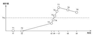
- FIG. 6 is a diagram illustrating an example of statistical values used for detection processing in a relay device according to a comparative example of the embodiment of the present disclosure.
- the horizontal axis shows time
- the vertical axis shows statistical values.
- FIG. 6 shows the statistical values T1 to T9 calculated by the calculation unit 12 based on the reception times t1 to t9 of the target messages M1 to M9 shown in FIG.
- the reception interval x3 becomes a value larger than the average value ⁇ , so the calculated statistical value T3 increases. Furthermore, since the target messages M4 to M7 arrive at the relay device at very short intervals, the reception intervals x4 to x7 become values smaller than the average value ⁇ , so the calculated statistical values T4 to T7 gradually increase. do.
- the relay device determines that an abnormality has occurred in the network 201 when the receiving interval x of the target message M becomes shorter due to a burst phenomenon even though no fraudulent message has arrived. .
- a method can be considered in which the reception interval x of the target message M that arrived during the period in which the burst phenomenon occurs is excluded from the detection process.
- this method if a fraudulent message arrives during a period when a burst phenomenon is occurring, the fraudulent message cannot be detected.
- the relay device 101 solves the above problem with the following configuration.
- the processing unit 14 detects a delayed message DEM, which is a target message M whose reception interval x is larger than the transmission cycle Cm by a predetermined value or more.
- the processing unit 14 compares the reception interval x with a predetermined threshold ThD. By doing so, it is determined whether the target message M is a delayed message DEM such as the above-described target message M3.
- the threshold ThD is a threshold used to detect the delayed message DEM, and is, for example, twice the transmission period Cm of the periodic message.
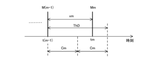
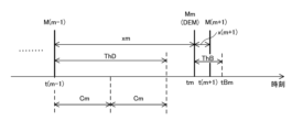
- FIG. 7 is a diagram illustrating an example of the reception time of the target message received by the relay device according to the embodiment of the present disclosure.
- the horizontal axis indicates time.
- the processing unit 14 determines that the target message Mm is not a delayed message DEM. In this case, the processing unit 14 calculates the statistical value Tm of the reception interval xm. The processing unit 14 then compares the calculated statistical value Tm with the threshold value Thx, and determines whether an abnormality has occurred in the network 201 based on the comparison result.
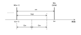
- FIG. 8 is a diagram illustrating another example of the reception time of the target message received by the relay device according to the embodiment of the present disclosure.
- the horizontal axis indicates time.
- the processing unit 14 determines that the target message Mm is a delayed message DEM. In this case, the processing unit 14 suspends calculation of the statistical value T of the reception interval x of the delayed message DEM until calculation time tB, which is the time when the threshold ThB is added to the reception time t of the delayed message DEM. That is, the processing unit 14 suspends calculation of the statistical value Tm of the reception interval xm until calculation time tBm, which is the time when the threshold ThB is added to the reception time tm of the target message Mm, which is the delayed message DEM. Then, the processing unit 14 waits for the calculation unit 12 to save the reception interval x(m+1) of the target message M(m+1) next to the target message Mm in the storage unit 15.
- the threshold ThB is set in advance based on the IFG (InterFrame Gap) of the frame in which the message is stored.
- the threshold ThB is a value obtained by adding a predetermined margin set based on fluctuations in frame transmission timing to the frame transmission time according to the minimum IFG.
- the threshold ThB may be a value obtained by subtracting a predetermined value from the transmission cycle Cm.
- the processing unit 14 When the processing unit 14 detects the delayed message DEM, it determines whether a burst phenomenon has occurred.
- the processing unit 14 determines whether a burst phenomenon has occurred depending on whether a new target message M arrives at the relay device 101 by the calculation time tB for the delayed message DEM. do. Note that, if a new message other than the target message M arrives at the relay device 101 by the calculation time tB, the processing unit 14 updates the calculation time tB to a time obtained by adding the threshold ThB to the reception time of the new message. You may.
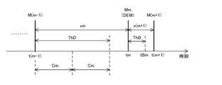
- FIG. 9 is a diagram illustrating an example of the reception time of the target message received by the relay device according to the embodiment of the present disclosure.
- the horizontal axis indicates time.
- FIG. 9 shows the reception time t(m+1) of the target message M(m+1) received by the communication processing unit 11 after the reception time tm shown in FIG.
- the processing unit 14 calculates the calculation time tBm for the target message Mm before the communication processing unit 11 receives the next target message M(m+1) of the target message Mm, which is the delayed message DEM. If it has arrived, it is determined that a burst phenomenon has not occurred. That is, if the calculation time tBm arrives before the reception interval x(m+1) and reception time t(m+1) of the target message M(m+1) are stored in the storage unit 15 by the calculation unit 12, the processing unit 14 calculates It is determined that no burst phenomenon has occurred.
- the processing unit 14 cancels the above-mentioned suspension and calculates the statistical value Tm of the reception interval xm according to the above-mentioned equations (1) and (2).
- the processing unit 14 compares the calculated statistical value Tm with the threshold value Thx, and determines whether an abnormality has occurred in the network 201 based on the comparison result.
- FIG. 10 is a diagram illustrating another example of the reception time of the target message received by the relay device according to the embodiment of the present disclosure.
- the horizontal axis indicates time.
- FIG. 10 shows the reception time t(m+1) of the target message M(m+1) received by the communication processing unit 11 after the reception time tm shown in FIG.
- the processing unit 14 receives the target message M(m+1) next to the target message Mm, which is the delayed message DEM, by the calculation time tBm for the target message Mm, the communication processing unit 11 , it is determined that a burst phenomenon has occurred at the reception time tm of the target message Mm. That is, if the receiving interval x(m+1) and the receiving time t(m+1) of the target message M(m+1) are stored in the storage unit 15 by the calculating unit 12 before the calculation time tBm arrives, the processing unit 14 calculates the following: It is determined that a burst phenomenon has occurred at the reception time tm of the target message Mm.
- the processing unit 14 determines that a burst phenomenon has occurred at the reception time tm of the target message Mm, it outputs burst occurrence information including the reception time t(m+1) of the target message M(m+1) to the calculation unit 12.
- the calculation unit 12 determines whether the burst phenomenon has ended based on the end determination time tE, which is the time when the target message M is received by the threshold ThB. Determine.
- the calculation unit 12 calculates the target message M(m+q+1) by the end determination time tE(m+q+1) for the target message M(m+q+1). If the next target message M(m+q+2) is received by the communication processing unit 11, it is determined that the burst phenomenon continues. That is, the calculation unit 12 determines that if the communication processing unit 11 outputs a message CP including a timestamp indicating the reception time t(m+q+2) before the end determination time tE(m+q+1) arrives, the burst phenomenon continues. It is determined that the Here, q is a positive integer.
- the calculation unit 12 calculates, before the communication processing unit 11 receives the next target message M(m+q+2) after the target message M(m+q+1).
- the end determination time tE(m+q+1) for the target message M(m+q+1) arrives, it is determined that the burst phenomenon has ended. That is, if the end determination time tE(m+q+1) arrives before the communication processing unit 11 outputs the message CP including the time stamp indicating the reception time t(m+q+2), the calculation unit 12 determines that the burst phenomenon has ended. It is determined that If the calculation unit 12 determines that the burst phenomenon has ended, it outputs burst end information to the processing unit 14.
- the calculation unit 12 sets the end determination time tE to a time obtained by adding the threshold ThB to the reception time of the new message. You may update to That is, every time the calculation unit 12 receives a message CP from the communication processing unit 11 after the reception time t(m+1) indicated by the burst occurrence information, the calculation unit 12 calculates the ID included in the message CP regardless of the ID included in the received message CP.
- the end determination time tE is updated based on the timestamp received, and if the communication processing unit 11 does not output the next message CP by the time the end determination time tE arrives, it is determined that the burst phenomenon has ended. Good too.
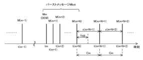
- the processing unit 14 counts a plurality of burst messages Mbst including the detected delayed message DEM and one or more target messages M whose reception interval x is equal to or less than the threshold ThB, which are received following the delayed message DEM. do. That is, the processing unit 14 processes a plurality of target messages M that are successively received by the communication processing unit 11, and the target message M that is the delayed message DEM and the reception interval x following the target message M are set as a threshold value. One or more target messages M whose value is less than or equal to ThB are counted as burst messages Mbst.
- the processing unit 14 counts the burst messages Mbst, which are the target messages M received by the communication processing unit 11 during the period in which the burst phenomenon occurs.
- the processing unit 14 determines that a burst phenomenon has occurred at the reception time tm of the target message Mm based on the comparison result between the reception interval x(m+1) and the threshold value ThB, the processing unit 14 determines that the target message Mm is It is determined that the target message M(m+1) is the first burst message Mbst and the second burst message Mbst, and "2", which is the count value CNT of the burst message Mbst, is held.
- FIG. 11 is a diagram illustrating an example of the reception time of the target message received by the relay device according to the embodiment of the present disclosure.
- the horizontal axis indicates time.
- FIG. 11 shows reception times t of a plurality of target messages M received by the communication processing unit 11 after the reception time tm shown in FIG.
- the processing unit 14 uses the calculation unit 12 to calculate the reception interval x(m+n) and reception time t(m+n) of the target message M(m+n) in the storage unit 15. Each time the count value CNT is saved, the count value CNT is incremented and updated.
- n is an integer of 2 or more.
- the processing unit 14 sets the count value CNT to “3”. ”.
- the processing unit 14 sets the count value CNT to “N+1”. Update to.
- the processing unit 14 ends counting if the next target message M is not received by the communication processing unit 11 within a predetermined time from the reception time t of the target message M, which is the burst message Mbst. More specifically, when the processing unit 14 receives burst end information from the calculation unit 12, it ends counting the burst messages Mbst.
- the processing unit 14 determines whether to perform detection processing based on the reception interval x of the plurality of burst messages Mbst.
- the processing unit 14 when the count value CNT is less than or equal to the threshold value ThC, the processing unit 14 does not perform the detection process based on the reception interval x of at least one of the plurality of burst messages Mbst. Specifically, when the count value CNT is equal to or less than the threshold value ThC, the processing unit 14 limits the use of the reception interval x of at least one burst message Mbst among the plurality of burst messages Mbst in the detection process. do. More specifically, when the processing unit 14 finishes counting the burst messages Mbst, it compares the count value CNT and the threshold value ThC. When the count value CNT is less than or equal to the threshold value ThC, the processing unit 14 discards all the reception intervals x of the burst messages Mbst without using them for the detection process.
- the processing unit 14 determines the threshold ThC used for comparison with the count value CNT, depending on the reception interval x of the target message M, which is the delayed message DEM.
- FIG. 12 is a diagram illustrating an example of a correspondence table stored in the storage unit in the relay device according to the embodiment of the present disclosure.
- the storage unit 15 stores a correspondence table Tb1 showing the correspondence between the reception interval x of the delayed message DEM and the threshold value ThC.
- the threshold value ThC is calculated from the reception time t of the target message M immediately before the delayed message DEM, assuming that the target message M arrives at the relay device 101 at a timing according to the transmission cycle Cm. It is set to a value that is the sum of the number of target messages M received by the communication processing unit 11 during the period up to reception time t of the delayed message DEM and a predetermined margin.
- the processing unit 14 acquires the threshold ThC corresponding to the reception interval xm of the target message Mm determined to be the delayed message DEM from the correspondence table Tb1 in the storage unit 15. As an example, if the reception interval xm of the target message Mm determined to be the delayed message DEM is four times or more the transmission cycle Cm and less than five times the transmission cycle Cm, the processing unit 14 uses the threshold value Obtain "5" as ThC.
- the processing unit 14 compares the acquired threshold ThC and the count value CNT, and if the count value CNT is less than or equal to the threshold ThC, the processing unit 14 selects the target message Mm which is the burst message Mbst. , M(m+1)..., M(m+N), the reception intervals xm, x(m+1)..., x(m+N) are discarded without being used in the detection process.
- the processing unit 14 calculates the receiving interval xm without calculating the statistical values Tm, T(m+1)..., T(m+N) of the receiving interval xm, x(m+1)..., x(m+N). , x(m+1) . . . , x(m+N) are deleted from the storage unit 15.
- the process of detecting the reception interval x of the burst messages Mbst is performed. By discarding the data without using it, it is possible to suppress false detections due to the occurrence of a burst phenomenon.
- the processing unit 14 determines that a burst phenomenon has occurred, it suspends the detection process until it finishes counting the burst messages Mbst, and restarts the detection process after it finishes counting the burst messages Mbst.
- the processing unit 14 receives the target message M(m+N). At time t(m+N), the burst phenomenon ends, and it is determined that the target message M(m+N+1) is not a delayed message DEM, and the statistical value T(m+N+1) of the reception interval x(m+N+1) is calculated. More specifically, the processing unit 14 uses the statistical value T(m-1) of the target message M(m-1) immediately before the burst message Mbst, instead of the statistical value T(m+N) of the reception interval x(m+N). The statistical value T(m+N+1) is calculated using the above equation (1).
- the processing unit 14 compares the calculated statistical value T(m+N+1) with the threshold value Thx, and determines whether an abnormality has occurred in the network 201 based on the comparison result.
- the processing unit 14 stores the reception interval x(m+N+2) of the target message M(m+N+2) in the storage unit 15 by the calculation unit 12, and if the reception interval x(m+N+2) is less than the threshold ThD, It is determined that the target message M(m+N+2) is not a delayed message DEM, and the statistical value T(m+N+2) of the reception interval x(m+N+2) is calculated.
- the processing unit 14 compares the calculated statistical value T(m+N+2) with the threshold value Thx, and determines whether an abnormality has occurred in the network 201 based on the comparison result.
- the processing unit 14 calculates the statistical value T(m+N+1) of the reception interval x(m+N+1) when it is determined that the burst phenomenon has ended at the reception time t(m+N) of the target message M(m+N). Instead, the reception interval x(m+N+1) may be deleted from the storage unit 15. In this case, the processing unit 14 waits for the calculation unit 12 to save the reception interval x(m+N+2) in the storage unit 15, and instead of the statistical value T(m+N+1) of the reception interval x(m+N+1), Using the statistical value T(m-1) of the target message M(m-1), the statistical value T(m+N+2) is calculated according to the above equation (1).
- the processing unit 14 performs a detection process based on the reception interval x of the burst message Mbst.
- the processing unit 14 compares the threshold ThC and the count value CNT, and if the count value CNT is larger than the threshold ThC, the processing unit 14 selects the target message Mm,M(m+1) which is the burst message Mbst. ..., M(m+N), receive interval xm, x(m+1)..., x(m+N) statistical values Tm, T(m+1)..., T(m+N) are calculated.
- the processing unit 14 compares the calculated statistical values Tm, T(m+1)..., T(m+N) with the threshold value Thx, and determines whether an abnormality has occurred in the network 201 based on the comparison result. Determine whether or not there is one.
- the processing unit 14 is configured to calculate the statistical value T of the reception interval x and perform the detection process based on the calculated statistical value T, the present invention is not limited to this.
- the processing unit 14 may be configured to perform the detection process without calculating the statistical value T.
- the processing unit 14 calculates a moving average value A of the reception interval x of the most recent p target messages M received by the communication processing unit 11, and performs the detection process based on the calculated moving average value A.
- . p is an integer of 2 or more.
- the moving average value A is an example of a detection index.
- the processing unit 14 calculates the movement of the reception interval xm, x(m-1), x(m-2)..., x(m-p+1). Calculate the average value Am.
- the reception intervals x(m-1), x(m-2), . . . , x(m-p+1) are examples of reference information regarding the target message M.
- the reception intervals x(m-1), x(m-2), . . . , x(m-p+1) are also referred to as reference intervals rm.
- the moving average value Am increases or decreases depending on the relationship between the reception interval xm of the target message Mm and the reference interval rm.
- the moving average value A calculated by the processing unit 14 is calculated from reception time t5 to reception time t13. gradually decreases over the period of .
- the processing unit 14 detects an abnormality in the network 201 based on the calculated moving average value A and a predetermined threshold Thy. More specifically, the processing unit 14 compares the calculated moving average value A and the threshold value Thy. If the moving average value A is equal to or greater than the threshold value Thy, the processing unit 14 determines that no abnormality has occurred in the network 201. On the other hand, if the moving average value A is less than the threshold value Thy, the processing unit 14 determines that an abnormality has occurred in the network 201.
- the processing unit 14 discards the reception interval x of the burst message Mbst without using it for calculating the moving average value A. Then, when the reception interval x of the target message M received next to the burst message Mbst is equal to or greater than a predetermined value, the processing unit 14 selects the most recent p messages received by the communication processing unit 11, excluding the burst message Mbst. A moving average value A of the reception interval x of the target message M is calculated, and a detection process is performed based on the calculated moving average value A.
- FIG. 13 is a flowchart defining an example of an operation procedure when the relay device according to the embodiment of the present disclosure performs detection processing.
- relay device 101 waits for the arrival of target message M (NO in step S102), and upon receiving target message M (YES in step S102), the reception interval x of the received target message M is is calculated (step S104).
- the relay device 101 determines that the received target message M is not a delayed message DEM, and Detection processing is performed based on the More specifically, the relay device 101 calculates a statistical value T of the reception interval x, compares the calculated statistical value T with a threshold value Thx, and determines whether an abnormality has occurred in the network 201 based on the comparison result. Determine whether or not the If the relay device 101 determines in the detection process that an abnormality has occurred in the network 201, it transmits, for example, alarm information to a higher-level device outside the communication system 301 (step S108).
- the relay device 101 waits for the arrival of a new target message M (NO in step S102).
- the relay device 101 determines that the received target message M is a delayed message DEM, and determines whether a burst phenomenon has occurred. Determine whether More specifically, the relay device 101 waits for the arrival of the next target message M of the delayed message DEM or the arrival of the calculation time tB for the delayed message DEM, and waits for the arrival of the next target message M of the delayed message DEM or the arrival of the calculation time tB for the delayed message DEM, and waits for the arrival of the next target message M of the delayed message DEM, and waits for the arrival of the next target message M of the delayed message DEM, and waits for the arrival of the next target message M of the delayed message DEM, and waits for the arrival of the next target message M of the delayed message DEM or the arrival of the calculation time tB for the delayed message DEM, and waits for the arrival of the next target message M of the delayed message DEM. If the message M is received, it is determined that a burst phenomenon has occurred, and
- the relay device 101 determines that a burst phenomenon has not occurred (YES in step S112), it performs a detection process. More specifically, the relay device 101 calculates the statistical value T of the reception interval x of the delayed message DEM and the statistical value T of the reception interval x of the next target message M of the delayed message DEM, and calculates each of the calculated statistical values T. and a threshold value Thx, and based on the comparison result, it is determined whether an abnormality has occurred in the network 201 (step S108).
- the relay device 101 waits for the arrival of a new target message M (NO in step S102).
- the relay device 101 determines that a burst phenomenon is occurring (NO in step S112), it counts the burst messages Mbst. More specifically, the relay device 101 waits for the arrival of a new target message M, and counts burst messages Mbst, which are target messages M received during the period in which the burst phenomenon occurs (step S114).
- the relay device 101 performs a detection process based on the reception interval x of the burst message Mbst. More specifically, the relay device 101 calculates each statistical value T of the reception interval x of a plurality of burst messages Mbst, compares each calculated statistical value T with a threshold value Thx, and based on the comparison result, , it is determined whether an abnormality has occurred in the network 201 (step S108).
- the relay device 101 waits for the arrival of a new target message M (NO in step S102).
- the relay device 101 discards the reception interval x of the burst message Mbst (step S118).
- the relay device 101 waits for the arrival of a new target message M (NO in step S102).
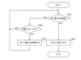
- FIG. 14 is a flowchart defining an example of an operation procedure when the relay device according to the embodiment of the present disclosure performs a process of counting burst messages.
- FIG. 14 shows details of step S114 in FIG. 13.
- relay device 101 waits for the elapse of threshold value ThB from reception time t of burst message Mbst and reception of a new target message M (NO in step S302 and NO in step S304). ), if a new target message M is received before the threshold ThB has elapsed from the reception time t of the burst message Mbst (NO in step S302 and YES in step S304), the received target message M is the burst message Mbst. It is determined that there is, and the count value CNT is incremented and updated (step S306).
- the burst phenomenon has ended. It is determined that the burst message Mbst is counted, and the counting of the burst messages Mbst is ended (step S308).
- the relay device 101 is configured to detect an abnormality in the network 201, but the present invention is not limited to this.
- a device different from the relay device 101 may function as a detection device and detect an abnormality in the network 201.
- the communication system 301 includes a detection device connected to the relay device 101 via the transmission line 10.
- the relay device 101 receives a message from the communication device 111, it transmits a mirror message, which is a copy of the received message, to the detection device via the transmission line 10.
- the detection device calculates the reception interval x and performs detection processing based on the reception time at the relay device 101 of the mirror message received from the relay device 101.
- the communication system 301 has a configuration in which the relay device 101 functioning as a detection device is directly connected to the transmission line 10, the present disclosure is not limited to this.
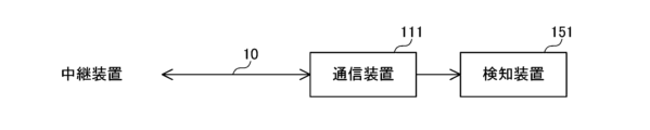
- FIG. 15 is a diagram illustrating an example of a network connection topology according to an embodiment of the present disclosure.
- a detection device 151 may be connected to transmission line 10 via communication device 111.
- the detection device 151 detects an abnormality in the network 201, for example, by monitoring messages received by the communication device 111. More specifically, the communication device 111 outputs the received message to the detection device 151.
- the detection device 151 includes a calculation section 12, a processing section 14, and a storage section 15.
- the calculation unit 12 in the detection device 151 obtains the reception time t of the target message M received by the communication device 111, and calculates the reception interval x based on the obtained reception time t.
- the storage unit 15 is configured to store the correspondence table Tb1, but the present invention is not limited to this.
- FIG. 16 is a diagram showing another example of the correspondence table stored in the storage unit in the relay device according to the embodiment of the present disclosure.
- the storage unit 15 stores a correspondence table Tb2 indicating the correspondence between the reception interval x of the delayed message DEM and the threshold value ThC. It may be a stored configuration.
- the threshold value ThC is calculated from the reception time t of the target message M immediately before the delayed message DEM, assuming that the target message M arrives at the relay device 101 at a timing according to the transmission cycle Cm.
- the storage unit 15 may have a configuration in which the correspondence tables Tb1 and Tb2 are not stored.
- the processing unit 14 uses a predetermined calculation formula to calculate the threshold ThC based on the reception interval x and transmission cycle Cm of the target message M determined to be the delayed message DEM.
- the processing unit 14 uses the reception interval x of all burst messages Mbst without using it for the detection process.
- the configuration is described as being discarded, the present invention is not limited to this.
- the processing unit 14 may be configured to discard the reception interval x of some burst messages Mbst while using the reception interval x of some other burst messages Mbst in the detection process.
- the processing unit 14 uses the reception interval x of the delayed message DEM among the plurality of burst messages Mbst in the detection process, while discarding the reception interval x of one or more burst messages Mbst other than the delayed message DEM.
- the processing unit 14 is configured to perform a detection process based on the reception interval x of the burst message Mbst when the count value CNT is larger than the threshold value ThC.
- the processing unit 14 may be configured not to perform the detection process based on the reception interval x of the burst message Mbst when the count value CNT is larger than the threshold value ThC. For example, if the count value CNT is larger than the threshold ThC, the processing unit 14 determines that an abnormality has occurred in the network 201 without performing any detection processing.
- the processing unit 14 determines the threshold value ThC used for comparison with the count value CNT according to the reception interval x of the target message M, which is the delayed message DEM.
- the present invention is not limited to this configuration.
- the processing unit 14 may be configured to use a predetermined threshold ThC for comparison with the count value CNT, regardless of the reception interval x of the target message M, which is the delayed message DEM.
- the processing unit 14 when it is determined that a burst phenomenon has occurred, the processing unit 14 suspends the detection process until the count of the burst messages Mbst is finished, and counts the burst messages Mbst.
- the processing unit 14 may perform the detection process after the fact based on the predetermined number of reception intervals x stored in the storage unit 15 by the calculation unit 12.
- the processing unit 14 may be configured not to suspend or restart the detection process.
- the processing unit 14 discards the reception interval x of the burst message Mbst, which is a part of the reception interval x stored in the storage unit 15, based on the comparison result between the count value CNT and the threshold value ThC. , the detection process is performed based on the remaining reception interval x.
- the processing unit 14 is configured to receive burst end information from the calculation unit 12 and end counting of the burst messages Mbst; however, the present disclosure is not limited to this. It's not a thing.
- the processing unit 14 may be configured to determine the end of the burst phenomenon based on the comparison result between the reception interval x and the threshold value ThB, and end the counting. More specifically, if the reception interval x(m+N+1) of the target message M(m+N+1) is larger than the threshold ThB, the processing unit 14 determines that a burst phenomenon occurs at the reception time t(m+N) of the target message M(m+N). It is determined that the burst message DM has ended, and the count of burst messages DM is ended.
- the calculation unit 12 calculates the reception interval x of the target message M.
- the processing unit 14 performs a detection process to detect an abnormality in the network 201 based on the reception interval x calculated by the calculation unit 12.
- the processing unit 14 processes a delayed message DEM which is a target message M whose reception interval x is larger than the transmission cycle Cm by a predetermined value or more, and one or more messages whose reception interval x is equal to or less than a predetermined value and which is received following the delayed message DEM.
- a plurality of burst messages Mbst including the target message M are counted. Based on the count value CNT of the burst messages Mbst, the processing unit 14 determines whether to perform detection processing based on the reception interval x for at least one of the plurality of burst messages Mbst.
- the use of the reception interval x of the burst message Mbst in the detection process is restricted based on the count value CNT of the burst message Mbst.
- a plurality of burst messages Mbst that are unlikely to include a fraudulent target message M can be excluded from detection processing targets, and false detection due to the occurrence of a burst phenomenon can be suppressed. Therefore, abnormalities in the network 201 can be detected more accurately.
- Each process (each function) of the above-described embodiment is realized by a processing circuit (Circuitry) including one or more processors.
- the processing circuit may include an integrated circuit or the like in which one or more memories, various analog circuits, and various digital circuits are combined.
- the one or more memories store programs (instructions) that cause the one or more processors to execute each of the above processes.
- the one or more processors may execute each of the above processes according to the program read from the one or more memories, or may execute each of the above processes according to a logic circuit designed in advance to execute each of the above processes. May be executed.
- the above processors include a CPU (Central Processing Unit), a GPU (Graphics Processing Unit), a DSP (Digital Signal Processor), and an FPGA (Field Programming Unit). rammable Gate Array) and ASIC (Application Specific Integrated Circuit), etc., which are compatible with computer control. processor.
- the plurality of physically separated processors may cooperate with each other to execute each of the above processes.
- the processors installed in each of a plurality of physically separated computers cooperate with each other via networks such as a LAN (Local Area Network), a WAN (Wide Area Network), and the Internet to perform each of the above processes. May be executed.
- the above program may be installed in the above memory from an external server device etc.
- CD-ROM Compact Disc Read Only Memory
- DVD-ROM Digital Versatile Disk Read Only Memory
- semiconductors It may be distributed in a state stored in a recording medium such as a memory, and installed into the memory from the recording medium.
- a detection device that detects an abnormality in a network in which a plurality of target messages including periodic messages that are transmitted and received at a predetermined transmission cycle are transmitted and received, a calculation unit that calculates the reception interval of the target message; a detection unit that performs a detection process to detect an abnormality in the network based on the reception interval calculated by the calculation unit; detecting the delayed message, which is the target message, the reception interval of which is greater than the transmission cycle by a predetermined value; and a counting unit that counts a plurality of burst messages including the target message, The detection unit determines whether or not to perform the detection process based on the reception interval for at least one of the plurality of burst messages based on the count value by the count unit, The detection unit discards the reception interval of the plurality of burst messages when the count value by the counting unit is less than or equal to the threshold value, and discards the reception interval of the plurality of burst messages when the count value is larger than
- a detection device that detects an abnormality in a network in which a plurality of target messages including periodic messages that are transmitted and received at a predetermined transmission cycle are transmitted and received, Equipped with a processing circuit,
- the processing circuit includes: Calculate the reception interval of the target message, Performing a detection process to detect an abnormality in the network based on the calculated reception interval, detecting the delayed message, which is the target message, the reception interval of which is greater than the transmission cycle by a predetermined value; counting a plurality of burst messages including the target message; The detection device determines, based on the count value, whether or not to perform the detection process based on the reception interval for at least one of the plurality of burst messages.
Landscapes
- Engineering & Computer Science (AREA)
- Computer Networks & Wireless Communication (AREA)
- Signal Processing (AREA)
- Environmental & Geological Engineering (AREA)
- Data Exchanges In Wide-Area Networks (AREA)
Abstract
Priority Applications (3)
| Application Number | Priority Date | Filing Date | Title |
|---|---|---|---|
| US18/855,390 US20250337673A1 (en) | 2022-04-12 | 2022-12-16 | Detection device and detection method |
| JP2024514802A JPWO2023199552A1 (fr) | 2022-04-12 | 2022-12-16 | |
| CN202280090009.9A CN118592018A (zh) | 2022-04-12 | 2022-12-16 | 检测装置及检测方法 |
Applications Claiming Priority (2)
| Application Number | Priority Date | Filing Date | Title |
|---|---|---|---|
| JP2022065792 | 2022-04-12 | ||
| JP2022-065792 | 2022-04-12 |
Publications (1)
| Publication Number | Publication Date |
|---|---|
| WO2023199552A1 true WO2023199552A1 (fr) | 2023-10-19 |
Family
ID=88329547
Family Applications (1)
| Application Number | Title | Priority Date | Filing Date |
|---|---|---|---|
| PCT/JP2022/046331 Ceased WO2023199552A1 (fr) | 2022-04-12 | 2022-12-16 | Dispositif et procédé de détection |
Country Status (4)
| Country | Link |
|---|---|
| US (1) | US20250337673A1 (fr) |
| JP (1) | JPWO2023199552A1 (fr) |
| CN (1) | CN118592018A (fr) |
| WO (1) | WO2023199552A1 (fr) |
Citations (3)
| Publication number | Priority date | Publication date | Assignee | Title |
|---|---|---|---|---|
| JP2014187445A (ja) * | 2013-03-22 | 2014-10-02 | Toyota Motor Corp | ネットワーク監視装置及びネットワーク監視方法 |
| WO2017104112A1 (fr) * | 2015-12-16 | 2017-06-22 | パナソニック インテレクチュアル プロパティ コーポレーション オブ アメリカ | Procédé et serveur de traitement de sécurité |
| WO2021065068A1 (fr) * | 2019-09-30 | 2021-04-08 | 株式会社オートネットワーク技術研究所 | Dispositif de détection, véhicule, procédé de détection et programme de détection |
-
2022
- 2022-12-16 WO PCT/JP2022/046331 patent/WO2023199552A1/fr not_active Ceased
- 2022-12-16 US US18/855,390 patent/US20250337673A1/en active Pending
- 2022-12-16 CN CN202280090009.9A patent/CN118592018A/zh active Pending
- 2022-12-16 JP JP2024514802A patent/JPWO2023199552A1/ja active Pending
Patent Citations (3)
| Publication number | Priority date | Publication date | Assignee | Title |
|---|---|---|---|---|
| JP2014187445A (ja) * | 2013-03-22 | 2014-10-02 | Toyota Motor Corp | ネットワーク監視装置及びネットワーク監視方法 |
| WO2017104112A1 (fr) * | 2015-12-16 | 2017-06-22 | パナソニック インテレクチュアル プロパティ コーポレーション オブ アメリカ | Procédé et serveur de traitement de sécurité |
| WO2021065068A1 (fr) * | 2019-09-30 | 2021-04-08 | 株式会社オートネットワーク技術研究所 | Dispositif de détection, véhicule, procédé de détection et programme de détection |
Also Published As
| Publication number | Publication date |
|---|---|
| JPWO2023199552A1 (fr) | 2023-10-19 |
| CN118592018A (zh) | 2024-09-03 |
| US20250337673A1 (en) | 2025-10-30 |
Similar Documents
| Publication | Publication Date | Title |
|---|---|---|
| US11863569B2 (en) | Bus-off attack prevention circuit | |
| CN111344192B (zh) | 禁用恶意电子控制单元的系统、方法和计算机程序产品 | |
| US10911182B2 (en) | In-vehicle information processing for unauthorized data | |
| US20210226872A1 (en) | Abnormality detection method, abnormality detection apparatus, and abnormality detection system | |
| JP6566400B2 (ja) | 電子制御装置、ゲートウェイ装置、及び検知プログラム | |
| US20200021611A1 (en) | Fraud detection method, fraud detection device, and recording medium | |
| JP6828632B2 (ja) | 検知装置、検知方法および検知プログラム | |
| WO2014115455A1 (fr) | Dispositif réseau et système d'envoi et de réception de données | |
| CN108605004B (zh) | 通信系统 | |
| US11700271B2 (en) | Device and method for anomaly detection in a communications network | |
| JP2019126003A (ja) | 攻撃検知装置および攻撃検知方法 | |
| WO2023199552A1 (fr) | Dispositif et procédé de détection | |
| JP3971353B2 (ja) | ウィルス隔離システム | |
| US12028184B2 (en) | Controller area network module and method for the module | |
| JP7175858B2 (ja) | 情報処理装置および正規通信判定方法 | |
| WO2023127460A1 (fr) | Dispositif et procédé de détection | |
| CN105554041B (zh) | 一种检测基于流表超时机制的分布式拒绝服务攻击的方法 | |
| US12353544B2 (en) | Method for detecting and responding for attack on can network | |
| WO2024051193A1 (fr) | Procédé de détection en ligne pour un utilisateur d'accès, dispositif électronique et support lisible par ordinateur | |
| CN121619612A (zh) | 报文传输方法、装置、设备及存储介质 | |
| CN118104217A (zh) | 检测装置、检测方法和检测程序 | |
| KR20230077596A (ko) | Can 네트워크에서 공격을 탐지 및 대응하기 위한 방법 | |
| Yin et al. | Medium access control with packet length priority towards a real time Ethernet | |
| CN119051965A (zh) | Cpu攻击检测方法、装置、网络设备和可读存储介质 | |
| CN121077888A (zh) | 一种故障处理方法、设备以及存储介质 |
Legal Events
| Date | Code | Title | Description |
|---|---|---|---|
| 121 | Ep: the epo has been informed by wipo that ep was designated in this application |
Ref document number: 22937527 Country of ref document: EP Kind code of ref document: A1 |
|
| WWE | Wipo information: entry into national phase |
Ref document number: 202280090009.9 Country of ref document: CN |
|
| ENP | Entry into the national phase |
Ref document number: 2024514802 Country of ref document: JP Kind code of ref document: A |
|
| WWE | Wipo information: entry into national phase |
Ref document number: 18855390 Country of ref document: US |
|
| NENP | Non-entry into the national phase |
Ref country code: DE |
|
| 122 | Ep: pct application non-entry in european phase |
Ref document number: 22937527 Country of ref document: EP Kind code of ref document: A1 |
|
| WWP | Wipo information: published in national office |
Ref document number: 18855390 Country of ref document: US |