WO2023199687A1 - Dispositif de génération d'énergie - Google Patents
Dispositif de génération d'énergie Download PDFInfo
- Publication number
- WO2023199687A1 WO2023199687A1 PCT/JP2023/010051 JP2023010051W WO2023199687A1 WO 2023199687 A1 WO2023199687 A1 WO 2023199687A1 JP 2023010051 W JP2023010051 W JP 2023010051W WO 2023199687 A1 WO2023199687 A1 WO 2023199687A1
- Authority
- WO
- WIPO (PCT)
- Prior art keywords
- circuit
- generator
- output
- phase
- cutoff
- Prior art date
- Legal status (The legal status is an assumption and is not a legal conclusion. Google has not performed a legal analysis and makes no representation as to the accuracy of the status listed.)
- Ceased
Links
Images


Classifications
-
- H—ELECTRICITY
- H02—GENERATION; CONVERSION OR DISTRIBUTION OF ELECTRIC POWER
- H02M—APPARATUS FOR CONVERSION BETWEEN AC AND AC, BETWEEN AC AND DC, OR BETWEEN DC AND DC, AND FOR USE WITH MAINS OR SIMILAR POWER SUPPLY SYSTEMS; CONVERSION OF DC OR AC INPUT POWER INTO SURGE OUTPUT POWER; CONTROL OR REGULATION THEREOF
- H02M7/00—Conversion of AC power input into DC power output; Conversion of DC power input into AC power output
- H02M7/02—Conversion of AC power input into DC power output without possibility of reversal
- H02M7/04—Conversion of AC power input into DC power output without possibility of reversal by static converters
- H02M7/12—Conversion of AC power input into DC power output without possibility of reversal by static converters using discharge tubes with control electrode or semiconductor devices with control electrode
- H02M7/21—Conversion of AC power input into DC power output without possibility of reversal by static converters using discharge tubes with control electrode or semiconductor devices with control electrode using devices of a triode or transistor type requiring continuous application of a control signal
- H02M7/217—Conversion of AC power input into DC power output without possibility of reversal by static converters using discharge tubes with control electrode or semiconductor devices with control electrode using devices of a triode or transistor type requiring continuous application of a control signal using semiconductor devices only
- H02M7/219—Conversion of AC power input into DC power output without possibility of reversal by static converters using discharge tubes with control electrode or semiconductor devices with control electrode using devices of a triode or transistor type requiring continuous application of a control signal using semiconductor devices only in a bridge configuration
-
- H—ELECTRICITY
- H02—GENERATION; CONVERSION OR DISTRIBUTION OF ELECTRIC POWER
- H02H—EMERGENCY PROTECTIVE CIRCUIT ARRANGEMENTS
- H02H1/00—Details of emergency protective circuit arrangements
- H02H1/0007—Details of emergency protective circuit arrangements concerning the detecting means
-
- H—ELECTRICITY
- H02—GENERATION; CONVERSION OR DISTRIBUTION OF ELECTRIC POWER
- H02H—EMERGENCY PROTECTIVE CIRCUIT ARRANGEMENTS
- H02H7/00—Emergency protective circuit arrangements specially adapted for specific types of electric machines or apparatus or for sectionalised protection of cable or line systems, and effecting automatic switching in the event of an undesired change from normal working conditions
- H02H7/06—Emergency protective circuit arrangements specially adapted for specific types of electric machines or apparatus or for sectionalised protection of cable or line systems, and effecting automatic switching in the event of an undesired change from normal working conditions for dynamo-electric generators; for synchronous capacitors
-
- H—ELECTRICITY
- H02—GENERATION; CONVERSION OR DISTRIBUTION OF ELECTRIC POWER
- H02M—APPARATUS FOR CONVERSION BETWEEN AC AND AC, BETWEEN AC AND DC, OR BETWEEN DC AND DC, AND FOR USE WITH MAINS OR SIMILAR POWER SUPPLY SYSTEMS; CONVERSION OF DC OR AC INPUT POWER INTO SURGE OUTPUT POWER; CONTROL OR REGULATION THEREOF
- H02M1/00—Details of apparatus for conversion
- H02M1/32—Means for protecting converters other than automatic disconnection
-
- H—ELECTRICITY
- H02—GENERATION; CONVERSION OR DISTRIBUTION OF ELECTRIC POWER
- H02P—CONTROL OR REGULATION OF ELECTRIC MOTORS, ELECTRIC GENERATORS OR DYNAMO-ELECTRIC CONVERTERS; CONTROLLING TRANSFORMERS, REACTORS OR CHOKE COILS
- H02P29/00—Arrangements for regulating or controlling electric motors, appropriate for both AC and DC motors
- H02P29/02—Providing protection against overload without automatic interruption of supply
- H02P29/024—Detecting a fault condition, e.g. short circuit, locked rotor, open circuit or loss of load
-
- H—ELECTRICITY
- H02—GENERATION; CONVERSION OR DISTRIBUTION OF ELECTRIC POWER
- H02P—CONTROL OR REGULATION OF ELECTRIC MOTORS, ELECTRIC GENERATORS OR DYNAMO-ELECTRIC CONVERTERS; CONTROLLING TRANSFORMERS, REACTORS OR CHOKE COILS
- H02P9/00—Arrangements for controlling electric generators for the purpose of obtaining a desired output
- H02P9/006—Means for protecting the generator by using control
Definitions
- the present disclosure relates to a power generation device including a generator using a rotating field.
- a permanent magnet generator includes a stator having coils for each phase and a rotor serving as a field having a plurality of permanent magnets.
- the plurality of permanent magnets are arranged in the rotation direction of the rotor while alternating their polarities.
- the rotor's permanent magnets are constantly generating magnetic flux that intersects with the stator coils. Therefore, in principle, a permanent magnet generator continues to generate electricity as long as the rotor is rotating. That is, the permanent magnet generator continues to generate electricity even if a problem such as a short circuit occurs within the generator.
- Patent Document 1 discloses a protection circuit that stops power supply from a generator.
- the rotor of a permanent magnet generator constantly generates magnetic flux, so power generation cannot be stopped while the rotor is rotating. Therefore, if a short circuit occurs inside the generator, there is a concern that damage to the generator or related equipment connected to its subsequent stage will progress excessively.
- the present disclosure has been made in view of the above-mentioned circumstances, and aims to provide a power generation device that can prevent the progression of damage due to short circuits occurring within the generator.
- a power generation device includes a generator including a stator including a three-phase coil, a power conversion circuit that converts AC power output from the generator into DC power, and an output of the generator. a first cutoff circuit provided between the input of the power conversion circuit, a second cutoff circuit provided between the three-phase coil and the neutral point, and an output current flowing from the generator to the power conversion circuit. and a first monitoring circuit that outputs a first cutoff signal when the absolute value of the output current exceeds a first predetermined value; and a first monitoring circuit that monitors the total value of the output voltage of each phase of the generator. Additionally, a second monitoring circuit is provided that outputs a second cutoff signal when the absolute value of the total value exceeds a second predetermined value.
- the first cutoff circuit electrically cuts off the connection between the generator and the power conversion circuit in accordance with the output of the first cutoff signal or the second cutoff signal
- the second cutoff circuit includes: The connection between the three-phase coil and the neutral point is electrically cut off in response to the output of the first cutoff signal or the second cutoff signal.
- the first monitoring circuit monitors a voltage corresponding to the output current, which is obtained by a current sensor provided between the output of the generator and the input of the power conversion circuit, to monitor the output current.
- the power conversion circuit may include a pair of switching elements that function as rectifying elements in each phase, and the first monitoring circuit monitors the voltage of each of the pair of switching elements to monitor the output current.
- the generator may be a permanent magnet synchronous generator.
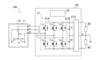
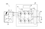
- FIG. 1 is a diagram showing an example of the configuration of a power generation device.
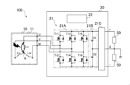
- FIG. 2 is a diagram showing an example of an intra-phase short circuit in the power generator shown in FIG. 1.
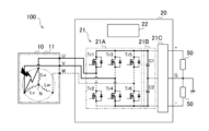
- FIG. 3A is a diagram showing an example of an inter-phase short circuit in the power generation device shown in FIG. 1.
- FIG. 3B is a diagram showing an example of an inter-phase short circuit in the power generation device shown in FIG. 1.
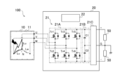
- FIG. 4 is a diagram showing an example of a ground fault in the power generator shown in FIG. 1.
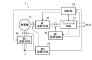
- FIG. 5 is a functional block diagram of a power generation device according to an embodiment of the present disclosure.
- FIG. 6 is a circuit diagram illustrating an example of a first monitoring circuit according to an embodiment of the present disclosure.
- FIG. 7 is a circuit diagram illustrating an example of a second monitoring circuit according to an embodiment of the present disclosure.
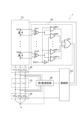
- FIG. 8 is a circuit diagram showing another example of the first monitoring circuit according to the embodiment of the present disclosure.
- FIG. 1 is a diagram showing an example of the configuration of a power generation device 100 in which the protection circuit according to the present embodiment is omitted from the configuration of the power generation device 1.
- power generation device 100 includes a generator 10 and a power converter 20.
- the power converter 20 includes a power conversion circuit (converter circuit) 21 and a control section 22.
- the power generation device 100 includes a first cutoff circuit 23, a second cutoff circuit 24, a first monitoring circuit 25, and a second monitoring circuit 26 (see FIGS. 5 to 9), which are protection circuits according to the present embodiment described later. do not have.
- the generator 10 includes a rotor (not shown) as a field and a stator 11 including a three-phase coil, and generates and outputs three-phase alternating current by rotation of the rotor.
- the generator 10 is, for example, a permanent magnet synchronous generator.
- the rotor has a plurality of permanent magnets arranged in the rotation direction of the rotor.
- the plurality of permanent magnets are arranged in the rotation direction while changing polarity alternately.
- the rotor is connected to a rotating shaft of a drive source (not shown) such as a turbine or an electric motor.
- the stator 11 includes an iron core (not shown) and a three-phase coil wound around the teeth (not shown) of the iron core.
- the three-phase coils are a U-phase coil Lu, a V-phase coil Lv, and a W-phase coil Lw.
- One end of each coil functions as an output end of the generator 10, and the other ends of each coil are connected to each other at a neutral point N. That is, the coil Lu, the coil Lv, and the coil Lw are connected in a so-called star connection.
- each coil may be composed of a plurality of coils connected in parallel or in series.
- the power conversion circuit 21 converts AC power output from the generator 10 into DC power.
- the power conversion circuit 21 outputs, for example, positive polarity and negative polarity DC voltages, respectively.
- the power conversion circuit 21 includes a switching circuit 21A, a smoothing circuit 21B, and a filter circuit 21C.
- the switching circuit 21A includes a pair of switching elements in each phase that function as rectifying elements. That is, the switching circuit 21A includes a pair of switching elements Tr1 and Tr2 provided for the U phase, a pair of switching elements Tr3 and Tr4 provided for the V phase, and a pair of switching elements Tr3 and Tr4 provided for the W phase. switching elements Tr5 and Tr6.
- Each switching element is a power semiconductor such as a MOSFET, thyristor, or IGBT. Turning on and off of each switching element is controlled by the control unit 22 so that a desired output voltage is finally obtained.
- the smoothing circuit 21B has a known configuration including a pair of capacitors (DC link capacitors) C1 and C2 connected in series, and smoothes each of the positive and negative pulsating currents output from the switching circuit 21A. . Note that the capacitors C1 and C2 are set at a ground potential and connected to the ground terminal G.
- the filter circuit 21C has a known configuration including an inductor (not shown) and the like.
- the filter circuit 21C outputs DC power at a voltage set by the control unit 22 while removing common mode noise and normal mode noise.
- a load 50 is connected between the positive output (+) and the ground terminal G of the filter circuit 21C, and between the negative output (-) and the ground terminal G, respectively.
- the control unit 22 controls the operation of the entire power generation device 100.
- the control unit 22 performs output control of a gate signal to the switching circuit 21A, feedback control for stabilizing the output voltage, acquisition of measurement values of various sensors (not shown), and the like.
- the control unit 22 may be configured as a computer, for example.
- FIG. 2 is a diagram showing an example of an intra-phase short circuit in the power generation device 100 shown in FIG. 1.
- An intra-phase short circuit in the generator 10 is a short circuit that occurs between two points in the conductive path of one phase.
- FIG. 2 shows, as an example, a short circuit that occurs between two points in the U-phase coil Lu. This short circuit shortens the length of the coil that intersects the magnetic flux, resulting in a decrease in the U-phase output voltage.
- the control unit 22 controls the switching circuit 21A to maintain the output voltage during normal operation. For example, the control unit 22 measures the output voltage from the filter circuit 21C, and controls the switching elements Tr1 to Tr6 to turn on and off based on this measured value. When the U-phase output voltage decreases under such control, the control unit 22 extends the on time of the switching elements Tr1 and Tr2, and increases the U-phase output current. In this case, there is a possibility that at least the short-circuited portion will be heated due to an increase in the output current.
- phase-to-phase short circuit 3A and 3B are diagrams showing an example of an inter-phase short circuit in the power generation device 100 shown in FIG. 1.
- An interphase short circuit in the generator 10 is a short circuit that occurs between conductive paths of different phases.
- 3A and 3B show, as an example, a short circuit that occurs between a U-phase conductive path (for example, coil Lu) and a V-phase conductive path (for example, coil Lv).
- the switching elements for example, Tr1 and Tr4
- the capacitors C1 and C2 A closed circuit is formed that returns to . Since the impedance of the closed circuit is approximately zero, a large DC current instantly flows from the capacitors C1 and C2. Therefore, there is a possibility that circuit components on the closed circuit may be burned out.
- a closed circuit passing through the neutral point N is also formed. Since the rotor does not stop rotating and current continues to flow while the short circuit continues, there is a possibility that heating of the short circuit area will progress.
- FIG. 4 is a diagram showing an example of a ground fault in the power generation device 100 shown in FIG. 1.
- a ground fault in the generator 10 is a short circuit that occurs between the coil of one phase and the ground.
- FIG. 4 shows, as an example, a short circuit that occurs between the U-phase conductive path (for example, the coil Lu) and the stator 11 of the generator 10.
- Tr1 switching element
- FIG. 5 is a functional block diagram of the power generation device 1 according to this embodiment.
- the power generating apparatus 1 includes a protection circuit in the event of a short circuit. That is, in addition to the generator 10 and the power conversion circuit 21, the power generation device 1 includes a first cutoff circuit 23, a second cutoff circuit 24, a first monitoring circuit 25, and a second monitoring circuit 26 as protection circuits.
- the first monitoring circuit 25 is a circuit that detects inter-phase short circuits and ground faults within the generator 10
- the second monitoring circuit 26 is a circuit that detects intra-phase short circuits within the generator 10. It is.
- the first cutoff circuit 23 is provided between the output of the generator 10 and the input of the power conversion circuit 21.
- the first cutoff circuit 23 receives a control signal from the control unit 22 and electrically cuts off the electrical connection between the generator 10 and the power conversion circuit 21 .
- This control signal is output from the control unit 22 in response to the output of the first cutoff signal outputted from the first monitoring circuit 25 or the second cutoff signal outputted from the second monitoring circuit 26.
- the first cutoff signal or the second cutoff signal itself may function as a control signal.
- the first cutoff circuit 23 includes a semiconductor switch S1 provided in the U phase, a semiconductor switch S2 provided in the V phase, and a semiconductor switch S3 provided in the W phase.
- the semiconductor switches S1 to S3 are power semiconductors such as bidirectional thyristors, MOSFETs, and IGBTs, for example.
- the second cutoff circuit 24 is provided between each of the three-phase coils Lu, Lv, and Lw and the neutral point N.
- the second cutoff circuit 24 receives a control signal from the control unit 22 and electrically cuts off the electrical connection between the three-phase coil and the power conversion circuit 21 .
- This control signal is output from the control unit 22 in response to the output of the first cutoff signal outputted from the first monitoring circuit 25 or the second cutoff signal outputted from the second monitoring circuit 26.
- the first cutoff signal or the second cutoff signal itself may function as a control signal.
- the second cutoff circuit 24 is also configured by a semiconductor switch S4 provided in the U phase, a semiconductor switch S5 provided in the V phase, and a semiconductor switch S6 provided in the W phase. There is.
- the semiconductor switches S4 to S6 are power semiconductors such as bidirectional thyristors, MOSFETs, and IGBTs, for example.
- FIG. 6 is a circuit diagram showing an example of the first monitoring circuit 25.
- the first monitoring circuit 25 includes shunt resistors R1 to R3, isolation amplifiers ISO1 to ISO3, comparators CMP1 to CMP6, and an OR circuit OR1.
- the shunt resistors R1 to R3 operate (function) as current sensors provided between the output of the generator 10 and the input of the power conversion circuit 21.
- the first monitoring circuit 25 monitors the output current flowing from the generator 10 to the power conversion circuit 21, and outputs a first cutoff signal when the absolute value of the output current exceeds a first predetermined value.
- the first predetermined value is set by the control unit 22 in consideration of fluctuations in the rotational speed of the generator 10, noise, etc., and is output as the threshold voltage Vth1.
- the first monitoring circuit 25 monitors the voltage corresponding to the output current obtained by the current sensor. For example, the first monitoring circuit 25 monitors the output current flowing from the generator 10 to the power conversion circuit 21 by using a shunt resistor R1 (R2, Monitor the voltage of R3).
- R1 shunt resistor
- the shunt resistor R1 is provided on the U-phase output path that connects the coil Lu and the power conversion circuit 21.
- the input of the isolation amplifier ISO1 is connected to both ends of the shunt resistor R1.
- the isolation amplifier ISO1 detects the voltage of the shunt resistor R1, and outputs the measured voltage to the ⁇ input of the comparator CMP1 and the + input of the comparator CMP2.
- a threshold voltage Vth1 which is a first predetermined value, is applied to the +input of the comparator CMP1. Further, an inverted voltage of the threshold voltage Vth1 is applied to the ⁇ input of the comparator CMP2.
- the shunt resistor R2 is provided on the V-phase output path that connects the coil Lv and the power conversion circuit 21.
- the input of the isolation amplifier ISO2 is connected to both ends of the shunt resistor R2.
- the isolation amplifier ISO2 detects the voltage of the shunt resistor R2, and outputs the measured voltage to the ⁇ input of the comparator CMP3 and the + input of the comparator CMP4.
- a threshold voltage Vth1 which is a first predetermined value, is applied to the +input of the comparator CMP3. Further, an inverted voltage of the threshold voltage Vth1 is applied to the ⁇ input of the comparator CMP4.
- the shunt resistor R3 is provided on the W-phase output path that connects the coil Lw and the power conversion circuit 21.
- the input of the isolation amplifier ISO3 is connected to both ends of the shunt resistor R3.
- the isolation amplifier ISO3 detects the voltage of the shunt resistor R1, and outputs the measured voltage to the ⁇ input of the comparator CMP5 and the + input of the comparator CMP6.
- a threshold voltage Vth1 which is a first predetermined value, is applied to the +input of the comparator CMP5. Further, an inverted voltage of the threshold voltage Vth1 is applied to the ⁇ input of the comparator CMP6.
- the outputs of the comparators CMP1 to CMP6 are connected to the input of the OR circuit OR1. Therefore, when the current value of any one of the shunt resistors R1 to R3 exceeds the absolute value of the current value corresponding to the threshold voltage Vth1, the OR circuit OR1 controls a signal at a level indicating this as the first cutoff signal. It outputs to section 22.
- the control unit 22 receives the first cutoff signal from the OR circuit OR1 and outputs a control signal to each of the first cutoff circuit 23 and the second cutoff circuit 24 to cut off the circuits.
- the current sensor provided between the output of the generator 10 and the input of the power conversion circuit 21 is not limited to the above-mentioned shunt resistor. That is, the current sensor may be a magnetic sensor such as a Hall sensor. In either case, a voltage proportional to the current flowing between the generator 10 and the power conversion circuit 21 can be obtained.
- FIG. 7 is a circuit diagram showing an example of the second monitoring circuit 26 according to the present embodiment.
- the second monitoring circuit 26 includes isolation amplifiers ISO7 to ISO9, comparators CMP13 and CMP14, and an OR circuit OR2.
- the second monitoring circuit 26 monitors the total value of the output voltages of each phase of the generator 10 (hereinafter referred to as total voltage). Further, the second monitoring circuit 26 outputs a second cutoff signal when the absolute value of the total voltage exceeds a second predetermined value.
- the second predetermined value is set by the control unit 22 in consideration of fluctuations such as noise, and is output as the threshold voltage Vth2.
- the second monitoring circuit 26 monitors, for example, the voltage at both ends (i.e., the output end and the neutral point end) of each coil Lu (Lv, Lw) forming the three-phase coil.
- One of the ends of the coil, the output end of the coil substantially functions as the output end of the generator 10.
- the other of the two ends of the coil, the neutral point end of the coil is connected to the neutral point N via the second cutoff circuit 24 .
- the insulation amplifier ISO7 detects the voltage across the coil Lu and outputs the measured voltage to the adder ADD1. If the voltage of the coil Lu is excessive, the voltage can be set to an appropriate voltage using a voltage dividing circuit (not shown) using a resistor.
- the insulation amplifier ISO8 detects the voltage value across the coil Lv, and outputs the measured voltage value to the adder ADD1. If the voltage of the coil Lv is excessive, the voltage can be set to an appropriate voltage using a voltage dividing circuit (not shown) using a resistor.
- the insulation amplifier ISO9 detects the voltage value across the coil Lw and outputs the measured voltage value to the adder ADD1. If the voltage of the coil Lw is excessive, the voltage can be set to an appropriate voltage using a voltage dividing circuit (not shown) using a resistor.
- the adder ADD1 calculates the sum of the voltages output from the isolation amplifiers ISO7 to ISO9, and outputs the sum to the ⁇ input of the comparator CMP13 and the + input of the comparator CMP14.
- a threshold voltage Vth2 which is a second predetermined value, is applied to the +input of the comparator CMP13. Further, an inverted voltage of the threshold voltage Vth2 is applied to the ⁇ input of the comparator CMP14.
- the voltage generated by the generator 10 is a pseudo three-phase sine wave alternating current using PWM (pulse width modulation). Unless ripples caused by PWM are taken into consideration, the voltages of each phase change in the same waveform with a phase difference of 120 degrees. Therefore, when the generator 10 is operating normally, the sum of the voltage values of each phase becomes zero in principle. Therefore, the total value of the voltages appearing in the coils Lu, Lv, and Lw, ie, the output voltage of the adder ADD1, is also zero in principle. Conversely, if the current waveform of any one of the U-phase, V-phase, and W-phase is disturbed and the current balance collapses, the total value of the voltages appearing in the coils Lu, Lv, and Lw changes from zero. Therefore, the threshold voltage Vth2 is set, for example, to the maximum value of expected fluctuations such as ripple.
- the outputs of the comparators CMP13 and CMP14 are connected to the input of the OR circuit OR2. Therefore, when the output voltage of the adder ADD1 exceeds the absolute value of the threshold voltage Vth2, the OR circuit OR2 outputs a signal at a level indicating this to the control unit 22 as a second cutoff signal.
- the control unit 22 receives the second cutoff signal from the OR circuit OR2, and outputs a control signal to each of the first cutoff circuit 23 and the second cutoff circuit 24 to cut off the circuits.
- the second monitoring circuit 26 measures the voltage at the output terminal of the coil Lu (Lv, Lw) instead of measuring the voltage across the coil Lu (Lv, Lw). and the neutral point N may be measured.
- the output voltage of the phase in which the intra-phase short circuit occurs decreases. That is, the voltage of each phase in which a short circuit has occurred is lower than the voltage of a phase in which a short circuit has not occurred.
- the second monitoring circuit 26 monitors the total value of the output voltage of each phase of the generator 10.
- the voltage of any one of these coils Lu, Lv, and Lw decreases, so that the total value of the output voltages of each phase increases or decreases from zero.
- the OR circuit OR2 outputs a second cutoff signal to the control unit 22.
- the control unit 22 receives the second cutoff signal from the OR circuit OR2 and outputs a control signal to each of the first cutoff circuit 23 and the second cutoff circuit 24 to cut off the circuits.
- the first cutoff circuit 23 receives a control signal from the control unit 22 and turns off the semiconductor switches S1 to S3.
- the second cutoff circuit 24 also turns off the semiconductor switches S4 to S6 in response to a control signal from the control unit 22.
- the first monitoring circuit 25 monitors the output current flowing from the generator 10 to the power conversion circuit 21 using the voltages of the shunt resistors R1 to R3.
- the voltage of any one of these shunt resistors R1 to R3 increases.
- the OR circuit OR1 outputs a first cutoff signal to the control unit 22.
- the control unit 22 receives the first cutoff signal from the OR circuit OR1 and outputs a control signal to each of the first cutoff circuit 23 and the second cutoff circuit 24 to cut off the circuits.
- the first cutoff circuit 23 receives a control signal from the control unit 22 and turns off the semiconductor switches S1 to S3.
- the second cutoff circuit 24 also turns off the semiconductor switches S4 to S6 in response to a control signal from the control section 22.
- the power generation device 1 is applicable even in environments where the rotation of the rotor cannot be stopped immediately, that is, the power generation cannot be stopped immediately.
- a generator under such an environment is, for example, an aircraft generator.
- the power generator installed on the aircraft uses an electromagnetic synchronous generator (WFSG: Wound Field Synchronous Generator) that can stop excitation, while the aircraft also uses a clutch, etc. that cuts off the driving force from the turbine that is the driving source of the generator. It does not have a driving force cutoff mechanism. Therefore, the generator rotor continues to rotate while the turbine is rotating. Furthermore, generators mounted on aircraft are cooled using cooling oil. If the power generation device generates excessive heat due to a short circuit or the like within the generator, it is necessary to stop power generation in order to prevent the power generation device from catching fire and the cooling oil from catching fire.
- WFSG Wound Field Synchronous Generator
- the power generation device 1 does not use a filter element such as an inductor or a filter circuit to detect abnormal current. Therefore, power supply can be cut off in a short time (for example, within 200 ⁇ s). Therefore, it can be adopted even under the above-mentioned environment.
- FIG. 8 is a circuit diagram showing another example of the first monitoring circuit 25 according to this embodiment.
- the first monitoring circuit 25 may monitor the voltage of each of the pair of switching elements in order to monitor the output current flowing from the generator 10 to the power conversion circuit 21. That is, the first monitoring circuit 25 may monitor the voltage between two terminals through which the above-mentioned output current passes in each of all the switching elements Tr1 to Tr6.
- the circuit configuration from detection of each voltage to the OR circuit via the isolation amplifier and comparator is the same as that shown in FIG. In this modification, since the shunt resistors R1 to R3 can be omitted, a more rapid interrupting operation is possible.
- the generator 10 according to the present embodiment is not limited to a permanent magnet synchronous generator, and may be a generator of other types.
- the protection of the power generator according to the present embodiment is more effective for a power generator that cannot stop power generation due to rotation of the rotor when an abnormality occurs in the power generator.
Landscapes
- Engineering & Computer Science (AREA)
- Power Engineering (AREA)
- Control Of Eletrric Generators (AREA)
Abstract
Priority Applications (4)
| Application Number | Priority Date | Filing Date | Title |
|---|---|---|---|
| CA3248193A CA3248193A1 (fr) | 2022-04-15 | 2023-03-15 | Dispositif de génération d'énergie |
| JP2024514860A JP7811637B2 (ja) | 2022-04-15 | 2023-03-15 | 発電装置 |
| EP23788109.9A EP4510441A4 (fr) | 2022-04-15 | 2023-03-15 | Dispositif de génération d'énergie |
| US18/910,136 US20250047093A1 (en) | 2022-04-15 | 2024-10-09 | Power generation device |
Applications Claiming Priority (2)
| Application Number | Priority Date | Filing Date | Title |
|---|---|---|---|
| JP2022-067486 | 2022-04-15 | ||
| JP2022067486 | 2022-04-15 |
Related Child Applications (1)
| Application Number | Title | Priority Date | Filing Date |
|---|---|---|---|
| US18/910,136 Continuation US20250047093A1 (en) | 2022-04-15 | 2024-10-09 | Power generation device |
Publications (1)
| Publication Number | Publication Date |
|---|---|
| WO2023199687A1 true WO2023199687A1 (fr) | 2023-10-19 |
Family
ID=88329443
Family Applications (1)
| Application Number | Title | Priority Date | Filing Date |
|---|---|---|---|
| PCT/JP2023/010051 Ceased WO2023199687A1 (fr) | 2022-04-15 | 2023-03-15 | Dispositif de génération d'énergie |
Country Status (5)
| Country | Link |
|---|---|
| US (1) | US20250047093A1 (fr) |
| EP (1) | EP4510441A4 (fr) |
| JP (1) | JP7811637B2 (fr) |
| CA (1) | CA3248193A1 (fr) |
| WO (1) | WO2023199687A1 (fr) |
Citations (4)
| Publication number | Priority date | Publication date | Assignee | Title |
|---|---|---|---|---|
| US20070030606A1 (en) | 2005-07-25 | 2007-02-08 | Honeywell International, Inc. | System and method for fault protection for permanent magnet machines |
| JP2012120408A (ja) * | 2010-12-03 | 2012-06-21 | Kokusan Denki Co Ltd | 発電装置 |
| JP2016123222A (ja) * | 2014-12-25 | 2016-07-07 | 株式会社日本自動車部品総合研究所 | 電力変換装置 |
| WO2016180479A1 (fr) * | 2015-05-12 | 2016-11-17 | Thyssenkrupp Presta Ag | Miroir de courant réversible et son utilisation dans une communication bidirectionnelle |
Family Cites Families (4)
| Publication number | Priority date | Publication date | Assignee | Title |
|---|---|---|---|---|
| FR2933818B1 (fr) * | 2008-07-10 | 2010-09-03 | Alstom Transport Sa | Systeme d'alimentation electrique pour moteur triphase a aimants permanents. |
| JP5841748B2 (ja) * | 2011-06-03 | 2016-01-13 | 株式会社Ihiエアロスペース | 発電装置 |
| JP6211443B2 (ja) * | 2014-03-14 | 2017-10-11 | 日立オートモティブシステムズ株式会社 | 電動モータの制御装置 |
| US9800196B2 (en) * | 2014-04-23 | 2017-10-24 | Mitsubishi Electric Corporation | Control apparatus for AC rotary machine |
-
2023
- 2023-03-15 WO PCT/JP2023/010051 patent/WO2023199687A1/fr not_active Ceased
- 2023-03-15 CA CA3248193A patent/CA3248193A1/fr active Pending
- 2023-03-15 JP JP2024514860A patent/JP7811637B2/ja active Active
- 2023-03-15 EP EP23788109.9A patent/EP4510441A4/fr active Pending
-
2024
- 2024-10-09 US US18/910,136 patent/US20250047093A1/en active Pending
Patent Citations (4)
| Publication number | Priority date | Publication date | Assignee | Title |
|---|---|---|---|---|
| US20070030606A1 (en) | 2005-07-25 | 2007-02-08 | Honeywell International, Inc. | System and method for fault protection for permanent magnet machines |
| JP2012120408A (ja) * | 2010-12-03 | 2012-06-21 | Kokusan Denki Co Ltd | 発電装置 |
| JP2016123222A (ja) * | 2014-12-25 | 2016-07-07 | 株式会社日本自動車部品総合研究所 | 電力変換装置 |
| WO2016180479A1 (fr) * | 2015-05-12 | 2016-11-17 | Thyssenkrupp Presta Ag | Miroir de courant réversible et son utilisation dans une communication bidirectionnelle |
Non-Patent Citations (1)
| Title |
|---|
| See also references of EP4510441A4 |
Also Published As
| Publication number | Publication date |
|---|---|
| EP4510441A1 (fr) | 2025-02-19 |
| JPWO2023199687A1 (fr) | 2023-10-19 |
| JP7811637B2 (ja) | 2026-02-05 |
| CA3248193A1 (fr) | 2025-07-09 |
| EP4510441A4 (fr) | 2025-11-26 |
| US20250047093A1 (en) | 2025-02-06 |
Similar Documents
| Publication | Publication Date | Title |
|---|---|---|
| US10042011B2 (en) | Method to detect or monitor the demagnetization of a magnet | |
| Kastha et al. | Investigation of fault modes of voltage-fed inverter system for induction motor drive | |
| JP6480316B2 (ja) | モータ制御装置 | |
| TWI383575B (zh) | Winding switch of AC motor and its winding switching system | |
| JP5094805B2 (ja) | 電圧検出装置及びそれを用いた電力変換装置 | |
| EP3480937B1 (fr) | Enroulement à contrechamp dans un générateur électrique | |
| JP5057661B2 (ja) | 電動機駆動システム | |
| KR20030020372A (ko) | 무브러시 직류 드라이브 | |
| US9088150B2 (en) | Overvoltage clipping device for a wind turbine and method | |
| Chai et al. | Performance comparison and winding fault detection of duplex 2-phase and 3-phase fault-tolerant permanent magnet brushless machines | |
| US8451573B1 (en) | Overvoltage protection device for a wind turbine and method | |
| CN101714753A (zh) | 电动机的控制电路 | |
| JP7811637B2 (ja) | 発電装置 | |
| Haylock et al. | Operation of a fault tolerant PM drive for an aerospace fuel pump application | |
| Krautstrunk et al. | Remedial strategy for a permanent magnet synchronous motor drive | |
| TWI505625B (zh) | Power conversion system and its control method | |
| JP4560710B2 (ja) | 発電システム | |
| JP2015216746A (ja) | 過電圧保護回路 | |
| KR102860497B1 (ko) | 절연 열화 측정이 가능한 교류 전동기의 인버터 기반 구동 장치 | |
| CN107852126B (zh) | 用于运行变频器的方法和变频器 | |
| Zhu et al. | Fault remedial strategies in a fault-tolerant brushless permanent magnet AC motor drive with redundancy | |
| SU997168A1 (ru) | Устройство дл защиты трехфазного электродвигател , соединенного в звезду, от обрыва фазы | |
| JP4822138B2 (ja) | 発電システムおよびその運転方法 | |
| Kathir et al. | Fault analysis of induction motor | |
| Eickhoff et al. | Saturation interaction in a fault-tolerant induction machine drive due to a zero-sequence stator current |
Legal Events
| Date | Code | Title | Description |
|---|---|---|---|
| 121 | Ep: the epo has been informed by wipo that ep was designated in this application |
Ref document number: 23788109 Country of ref document: EP Kind code of ref document: A1 |
|
| WWE | Wipo information: entry into national phase |
Ref document number: 2024514860 Country of ref document: JP |
|
| WWE | Wipo information: entry into national phase |
Ref document number: 2023788109 Country of ref document: EP |
|
| NENP | Non-entry into the national phase |
Ref country code: DE |
|
| ENP | Entry into the national phase |
Ref document number: 2023788109 Country of ref document: EP Effective date: 20241115 |