WO2023204175A1 - 電極触媒層、膜電極接合体及び固体高分子形燃料電池 - Google Patents
電極触媒層、膜電極接合体及び固体高分子形燃料電池 Download PDFInfo
- Publication number
- WO2023204175A1 WO2023204175A1 PCT/JP2023/015309 JP2023015309W WO2023204175A1 WO 2023204175 A1 WO2023204175 A1 WO 2023204175A1 JP 2023015309 W JP2023015309 W JP 2023015309W WO 2023204175 A1 WO2023204175 A1 WO 2023204175A1
- Authority
- WO
- WIPO (PCT)
- Prior art keywords
- catalyst layer
- electrode catalyst
- polymer electrolyte
- fibrous material
- electrode
- Prior art date
- Legal status (The legal status is an assumption and is not a legal conclusion. Google has not performed a legal analysis and makes no representation as to the accuracy of the status listed.)
- Ceased
Links
Images


Classifications
-
- H—ELECTRICITY
- H01—ELECTRIC ELEMENTS
- H01M—PROCESSES OR MEANS, e.g. BATTERIES, FOR THE DIRECT CONVERSION OF CHEMICAL ENERGY INTO ELECTRICAL ENERGY
- H01M4/00—Electrodes
- H01M4/86—Inert electrodes with catalytic activity, e.g. for fuel cells
- H01M4/8663—Selection of inactive substances as ingredients for catalytic active masses, e.g. binders, fillers
-
- H—ELECTRICITY
- H01—ELECTRIC ELEMENTS
- H01M—PROCESSES OR MEANS, e.g. BATTERIES, FOR THE DIRECT CONVERSION OF CHEMICAL ENERGY INTO ELECTRICAL ENERGY
- H01M4/00—Electrodes
- H01M4/86—Inert electrodes with catalytic activity, e.g. for fuel cells
-
- H—ELECTRICITY
- H01—ELECTRIC ELEMENTS
- H01M—PROCESSES OR MEANS, e.g. BATTERIES, FOR THE DIRECT CONVERSION OF CHEMICAL ENERGY INTO ELECTRICAL ENERGY
- H01M4/00—Electrodes
- H01M4/86—Inert electrodes with catalytic activity, e.g. for fuel cells
- H01M4/88—Processes of manufacture
- H01M4/8803—Supports for the deposition of the catalytic active composition
- H01M4/881—Electrolytic membranes
-
- H—ELECTRICITY
- H01—ELECTRIC ELEMENTS
- H01M—PROCESSES OR MEANS, e.g. BATTERIES, FOR THE DIRECT CONVERSION OF CHEMICAL ENERGY INTO ELECTRICAL ENERGY
- H01M4/00—Electrodes
- H01M4/86—Inert electrodes with catalytic activity, e.g. for fuel cells
- H01M4/88—Processes of manufacture
- H01M4/8825—Methods for deposition of the catalytic active composition
- H01M4/8828—Coating with slurry or ink
-
- H—ELECTRICITY
- H01—ELECTRIC ELEMENTS
- H01M—PROCESSES OR MEANS, e.g. BATTERIES, FOR THE DIRECT CONVERSION OF CHEMICAL ENERGY INTO ELECTRICAL ENERGY
- H01M4/00—Electrodes
- H01M4/86—Inert electrodes with catalytic activity, e.g. for fuel cells
- H01M4/90—Selection of catalytic material
- H01M4/9008—Organic or organo-metallic compounds
-
- H—ELECTRICITY
- H01—ELECTRIC ELEMENTS
- H01M—PROCESSES OR MEANS, e.g. BATTERIES, FOR THE DIRECT CONVERSION OF CHEMICAL ENERGY INTO ELECTRICAL ENERGY
- H01M4/00—Electrodes
- H01M4/86—Inert electrodes with catalytic activity, e.g. for fuel cells
- H01M4/90—Selection of catalytic material
- H01M4/9075—Catalytic material supported on carriers, e.g. powder carriers
-
- H—ELECTRICITY
- H01—ELECTRIC ELEMENTS
- H01M—PROCESSES OR MEANS, e.g. BATTERIES, FOR THE DIRECT CONVERSION OF CHEMICAL ENERGY INTO ELECTRICAL ENERGY
- H01M4/00—Electrodes
- H01M4/86—Inert electrodes with catalytic activity, e.g. for fuel cells
- H01M4/90—Selection of catalytic material
- H01M4/9075—Catalytic material supported on carriers, e.g. powder carriers
- H01M4/9083—Catalytic material supported on carriers, e.g. powder carriers on carbon or graphite
-
- H—ELECTRICITY
- H01—ELECTRIC ELEMENTS
- H01M—PROCESSES OR MEANS, e.g. BATTERIES, FOR THE DIRECT CONVERSION OF CHEMICAL ENERGY INTO ELECTRICAL ENERGY
- H01M4/00—Electrodes
- H01M4/86—Inert electrodes with catalytic activity, e.g. for fuel cells
- H01M4/90—Selection of catalytic material
- H01M4/92—Metals of platinum group
- H01M4/925—Metals of platinum group supported on carriers, e.g. powder carriers
-
- H—ELECTRICITY
- H01—ELECTRIC ELEMENTS
- H01M—PROCESSES OR MEANS, e.g. BATTERIES, FOR THE DIRECT CONVERSION OF CHEMICAL ENERGY INTO ELECTRICAL ENERGY
- H01M4/00—Electrodes
- H01M4/86—Inert electrodes with catalytic activity, e.g. for fuel cells
- H01M4/90—Selection of catalytic material
- H01M4/92—Metals of platinum group
- H01M4/925—Metals of platinum group supported on carriers, e.g. powder carriers
- H01M4/926—Metals of platinum group supported on carriers, e.g. powder carriers on carbon or graphite
-
- H—ELECTRICITY
- H01—ELECTRIC ELEMENTS
- H01M—PROCESSES OR MEANS, e.g. BATTERIES, FOR THE DIRECT CONVERSION OF CHEMICAL ENERGY INTO ELECTRICAL ENERGY
- H01M8/00—Fuel cells; Manufacture thereof
- H01M8/10—Fuel cells with solid electrolytes
-
- H—ELECTRICITY
- H01—ELECTRIC ELEMENTS
- H01M—PROCESSES OR MEANS, e.g. BATTERIES, FOR THE DIRECT CONVERSION OF CHEMICAL ENERGY INTO ELECTRICAL ENERGY
- H01M8/00—Fuel cells; Manufacture thereof
- H01M8/10—Fuel cells with solid electrolytes
- H01M8/1004—Fuel cells with solid electrolytes characterised by membrane-electrode assemblies [MEA]
-
- H—ELECTRICITY
- H01—ELECTRIC ELEMENTS
- H01M—PROCESSES OR MEANS, e.g. BATTERIES, FOR THE DIRECT CONVERSION OF CHEMICAL ENERGY INTO ELECTRICAL ENERGY
- H01M8/00—Fuel cells; Manufacture thereof
- H01M8/10—Fuel cells with solid electrolytes
- H01M8/1016—Fuel cells with solid electrolytes characterised by the electrolyte material
- H01M8/1018—Polymeric electrolyte materials
- H01M8/102—Polymeric electrolyte materials characterised by the chemical structure of the main chain of the ion-conducting polymer
- H01M8/1023—Polymeric electrolyte materials characterised by the chemical structure of the main chain of the ion-conducting polymer having only carbon, e.g. polyarylenes, polystyrenes or polybutadiene-styrenes
-
- H—ELECTRICITY
- H01—ELECTRIC ELEMENTS
- H01M—PROCESSES OR MEANS, e.g. BATTERIES, FOR THE DIRECT CONVERSION OF CHEMICAL ENERGY INTO ELECTRICAL ENERGY
- H01M8/00—Fuel cells; Manufacture thereof
- H01M8/10—Fuel cells with solid electrolytes
- H01M8/1016—Fuel cells with solid electrolytes characterised by the electrolyte material
- H01M8/1018—Polymeric electrolyte materials
- H01M8/1039—Polymeric electrolyte materials halogenated, e.g. sulfonated polyvinylidene fluorides
-
- H—ELECTRICITY
- H01—ELECTRIC ELEMENTS
- H01M—PROCESSES OR MEANS, e.g. BATTERIES, FOR THE DIRECT CONVERSION OF CHEMICAL ENERGY INTO ELECTRICAL ENERGY
- H01M8/00—Fuel cells; Manufacture thereof
- H01M8/10—Fuel cells with solid electrolytes
- H01M2008/1095—Fuel cells with polymeric electrolytes
-
- Y—GENERAL TAGGING OF NEW TECHNOLOGICAL DEVELOPMENTS; GENERAL TAGGING OF CROSS-SECTIONAL TECHNOLOGIES SPANNING OVER SEVERAL SECTIONS OF THE IPC; TECHNICAL SUBJECTS COVERED BY FORMER USPC CROSS-REFERENCE ART COLLECTIONS [XRACs] AND DIGESTS
- Y02—TECHNOLOGIES OR APPLICATIONS FOR MITIGATION OR ADAPTATION AGAINST CLIMATE CHANGE
- Y02E—REDUCTION OF GREENHOUSE GAS [GHG] EMISSIONS, RELATED TO ENERGY GENERATION, TRANSMISSION OR DISTRIBUTION
- Y02E60/00—Enabling technologies; Technologies with a potential or indirect contribution to GHG emissions mitigation
- Y02E60/30—Hydrogen technology
- Y02E60/50—Fuel cells
Definitions
- the present disclosure relates to an electrode catalyst layer, a membrane electrode assembly, and a polymer electrolyte fuel cell.
- a fuel cell is a power generation system that generates electricity from a chemical reaction between hydrogen and oxygen.
- Fuel cells have features such as high efficiency, low environmental impact, and low noise compared to conventional power generation methods, and are attracting attention as a future clean energy source.
- polymer electrolyte fuel cells which can be used near room temperature, are seen as promising for use in in-vehicle power sources and household stationary power sources, and in recent years, various research and developments regarding polymer electrolyte fuel cells have been carried out. It is being said. Challenges for its practical use include improving battery performance such as power generation characteristics and durability, improving infrastructure, and reducing manufacturing costs.
- Polymer electrolyte fuel cells are generally constructed by stacking a large number of single cells.
- a single cell is a membrane electrode assembly in which a fuel electrode (anode) for supplying fuel gas and an oxygen electrode (cathode) for supplying an oxidizer are connected to both sides of a polymer electrolyte membrane through a gas flow path and a cooling water flow. It has a structure in which it is sandwiched between separators with channels.
- the fuel electrode (anode) and the oxygen electrode (cathode) include an electrode catalyst layer containing at least a catalytic material such as a platinum-based precious metal, a conductive carrier, and a polymer electrolyte, and a gas diffusion layer that has both gas permeability and conductivity. It is mainly composed of.
- the gas diffusion layer has the role of diffusing the gas supplied from the separator and supplying it into the electrode catalyst layer.
- the pores in the electrode catalyst layer are located beyond the separator through the gas diffusion layer, and serve as passages for transporting multiple substances.
- the pores of the fuel electrode are required to have the function of smoothly supplying hydrogen contained in the fuel gas to the three-phase interface, which is the redox reaction site.
- the pores of the oxygen electrode are required to have a function of smoothly supplying oxygen contained in the oxidant gas.
- the pores of the oxygen electrode are required to have a function of smoothly discharging water produced by the reaction.
- the electrode catalyst layer has sufficient gaps to allow produced water to be discharged smoothly and does not have a dense structure. It is.
- Patent Documents 1 and 2 As a means of controlling the structure of the electrode catalyst layer so that it does not become dense and improving power generation performance, for example, an electrode catalyst layer containing carbon or carbon fibers of different particle sizes has been proposed (Patent Documents 1 and 2).
- Patent Document 1 dense clogging of carbon particles in the electrode catalyst layer is suppressed by combining carbon particles having particle sizes that are moderately different from each other. Further, in Patent Document 2, carbon fibers having different fiber lengths are included, and the ratio thereof is set within a certain range, so that appropriate pores occupy a large number of pores in the electrode catalyst layer. On the other hand, when large particles with a large particle size and small particles with a small particle size are mixed, the small particles may enter the gaps between the large particles and become rather densely packed. Further, when the carbon material is only particles, cracks are likely to be induced in the catalyst layer, and the accompanying decrease in durability may become a problem.
- a fuel cell is a power generation system that generates electrical energy through a chemical reaction between hydrogen and oxygen and exhausts only water, and there are high expectations for fuel cells as a future energy source.
- fuel cells are classified into alkaline type, phosphoric acid type, solid polymer type, molten carbonate type, solid oxide type, etc.
- Polymer electrolyte fuel cells can be used at around room temperature, so they are expected to be widely used in automotive power supplies and home stationary power supplies. Therefore, in order to put polymer electrolyte fuel cells into practical use, research and development efforts are being actively conducted to improve power generation performance and durability, and to reduce costs.
- a polymer electrolyte fuel cell includes a polymer electrolyte membrane having proton conductivity, a fuel electrode as an anode, and an air electrode as a cathode.
- a fuel electrode and an air electrode sandwich the polymer electrolyte membrane in the thickness direction of the polymer electrolyte membrane.
- the fuel electrode has an electrode catalyst layer that separates the fuel gas into protons and electrons.
- the air electrode has an electrode catalyst layer that oxidizes protons transported through the polymer electrolyte membrane with an oxidizing agent containing oxygen and receives electrons from an external circuit.
- the electrode catalyst layers of the fuel electrode and the air electrode include a catalyst material such as a platinum-based noble metal, a carrier supporting the catalyst material, and a polymer electrolyte.
- the basic structure of a polymer electrolyte fuel cell is a single cell in which a gas diffusion layer and a separator are arranged on the opposite side of the polymer electrolyte membrane in each electrode catalyst layer of the fuel electrode and the air electrode. It is made up of multiple stacked cells.
- the gas diffusion layer is a layer that has conductivity and uniformly diffuses a reaction gas.
- the separator is a member that has a gas flow path and a cooling water flow path and plays the role of extracting electrons to an external circuit, and is disposed outside the gas diffusion layer.
- a membrane electrode assembly in which a fuel electrode and an air electrode are formed on both sides of a polymer electrolyte membrane is referred to as a membrane electrode assembly.
- a fuel gas containing hydrogen is supplied to the fuel electrode, and an oxidant gas containing oxygen is supplied to the air electrode, so that the following equations 1 and 2 are satisfied at the fuel electrode and the air electrode.
- the electrode reaction shown occurs and electricity is generated.
- Fuel electrode H 2 ⁇ 2H + +2e - (Formula 1)
- Air electrode 1/2O 2 +2H + +2e - ⁇ H 2 O... (Formula 2)
- fuel gas supplied to the fuel electrode is separated into protons and electrons by the catalyst material contained in the electrode catalyst layer of the fuel electrode.
- the separated protons move to the air electrode through the humidified polymer electrolyte and polymer electrolyte membrane included in the electrode catalyst layer of the fuel electrode.
- the separated electrons are taken out from the fuel electrode to an external circuit and move to the air electrode through the external circuit.
- the oxidant gas reacts with the protons and electrons that have migrated from the fuel electrode to generate water. Electric current is generated when electrons pass through an external circuit.
- the electrode catalyst layer of a fuel cell is generally formed of a thin film with a thickness of 100 ⁇ m or less, and so-called cracks, which occur in the electrode catalyst layer during manufacturing, have been cited as a problem.
- cracks occur, proton conduction paths and electron conduction paths within the electrode catalyst layer are interrupted, reducing power generation performance and durability.
- a technique disclosed in Patent Document 3 is known as a technique for improving the bonding strength of the electrode catalyst layer.
- the bonding strength of the electrode catalyst layer is improved by adding a fibrous material such as hydrophilic carbon whiskers to the electrode catalyst layer.
- An object of the present invention is to provide an electrode catalyst layer, a membrane electrode assembly, and a polymer electrolyte fuel cell, which are capable of the following and have good durability.
- the proton conduction resistance may significantly increase due to a decrease in the water content of the polymer electrolyte.
- the ratio of polymer electrolyte in the electrode catalyst layer is increased in order to improve proton conductivity, electron conductivity in the electrode catalyst layer may not be ensured, or power generation at high current density may not be possible due to water retention by the polymer electrolyte. The water that is sometimes discharged cannot be removed from the system, reducing power generation performance. Therefore, it is necessary to maintain power generation performance while suppressing the amount of polymer electrolyte in the catalyst layer to a small amount. Therefore, it is important to appropriately construct a proton conduction path within the electrode catalyst layer to which the fibrous material is added.
- the present inventors measured the amount of polymer electrolyte around the fibrous material in the electrode catalyst layer, and determined that the presence of the polymer electrolyte around the fibrous material above a certain level indicates that the electrode catalyst It has been found that the proton conduction path within the layer can be appropriately constructed and the above problems can be solved.
- One aspect of the present disclosure aims to provide an electrode catalyst layer, a membrane electrode assembly, and a polymer electrolyte fuel cell that have excellent initial power generation performance from a low current density region to a high current density region.
- An electrode catalyst layer used in a polymer electrolyte fuel cell comprising:
- the electrode catalyst layer includes a catalyst material, a conductive carrier supporting the catalyst material, a polymer electrolyte, and a fibrous material containing nitrogen atoms,
- the ratio of the number of nitrogen atoms to the total number of atoms of carbon, nitrogen, oxygen, fluorine, sulfur, and platinum elements is 2 at% or more and 20 at. % or less
- the specific region is a region that contains 50 area % or more of the fibrous material containing nitrogen atoms and does not contain the catalyst material and the conductive carrier. .
- a polymer electrolyte fuel cell comprising the membrane electrode assembly according to [8].
- Second invention group B One aspect of the present disclosure is an electrode catalyst layer joined to a polymer electrolyte membrane, the electrode catalyst layer including a catalyst, a fluorine-containing polymer electrolyte, and a fibrous material, the electrode catalyst layer having energy in a specific region of a cross section of the electrode catalyst layer.
- the ratio of the number of fluorine atoms to the total number of atoms of carbon, nitrogen, oxygen, fluorine, sulfur, and platinum elements obtained by dispersive X-ray spectroscopy is 0.2 at% or more, and the specific region is a fibrous material.
- the electrode catalyst layer is a region that contains 50 area% or more of a catalyst and does not contain a catalyst.
- the fibrous material may have an azole structure.
- the carrier includes a carrier that supports a catalyst and constitutes catalyst-supported particles together with the catalyst, and the content of the fibrous material is 5 parts by mass or more and 20 parts by mass or less, when the content of the carrier is 100 parts by mass.
- the specific region may be a region that does not contain a carrier.
- the polymer electrolyte may cover at least a portion of the surface of the fibrous material.
- the thickness of the polymer electrolyte covering the fibrous material may be 3 nm or more and 30 nm or less.
- the polymer electrolyte includes a proton-donating group, and the dry weight per mole of the proton-donating group of the polymer electrolyte may be 600 g/mol or more and 1200 g/mol or less.
- the average fiber length of the fibrous material may be 0.7 ⁇ m or more and 40 ⁇ m or less.
- the average fiber diameter of the fibrous material may be 10 nm or more and 500 nm or less.
- the fibrous material may have the ability to adsorb a polymer electrolyte.
- the adsorption capacity of the fibrous material to the polymer electrolyte may be 10 mg/g or more.
- Another aspect of the present disclosure is a membrane electrode assembly that includes a polymer electrolyte membrane and the above electrode catalyst layer, and the electrode catalyst layer is joined to the polymer electrolyte membrane.
- Yet another aspect of the present disclosure includes the membrane electrode assembly, a pair of gas diffusion layers sandwiching the membrane electrode assembly in the thickness direction of the membrane electrode assembly, and a membrane electrode assembly in the thickness direction of the membrane electrode assembly.
- This is a polymer electrolyte fuel cell including a bonded body and a pair of separators sandwiching a pair of gas diffusion layers.
- the first invention group A which is one aspect of the present disclosure, it is possible to improve the mass transportability and proton conductivity in the electrode catalyst layer, and to exhibit high power generation performance and good durability.
- An electrode catalyst layer, a membrane electrode assembly, and a polymer electrolyte fuel cell can be provided.
- an electrode catalyst layer a membrane electrode assembly, and a polymer electrolyte fuel cell that have excellent initial power generation performance from a low current density region to a high current density region. Ru.
- FIG. 2 is a cross-sectional view schematically showing an example of the cross-sectional structure of an electrode catalyst layer of the first invention group of the present disclosure.
- FIG. 2 is a schematic diagram showing an example of a cross section of an electrode catalyst layer of a first invention group and an example of a cross section of a first electrode catalyst layer of a second invention group.
- FIG. 3 is an explanatory diagram of fiber diameter distribution of fibers of the first invention group.
- FIG. 3 is an explanatory diagram of fiber diameters of fibers of the first invention group.
- a configuration example of a membrane electrode assembly according to the present embodiment of the first invention group is shown
- FIG. 5(a) is a plan view of the membrane electrode assembly seen from the oxygen electrode side of the electrode catalyst layer
- FIG. 5(b) is a plan view of the membrane electrode assembly according to the present embodiment of the first invention group. is a sectional view taken along line XX' in FIG. 5(a).
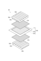
- FIG. 1 is an exploded perspective view showing a configuration example of a polymer electrolyte fuel cell of the first invention group.
- FIG. 3 is a cross-sectional view showing the structure of a membrane electrode assembly in an embodiment of the second group of inventions.
- FIG. 3 is a schematic diagram schematically showing the structure of a first electrode catalyst layer in an embodiment of the second invention group.
- FIG. 7 is a cross-sectional view showing the structure of catalyst-supported particles included in the first electrode catalyst layer in an embodiment of the second invention group.
- FIG. 3 is an exploded perspective view showing the configuration of a polymer electrolyte fuel cell according to an embodiment of the second group of inventions.
- the inventor of the present disclosure has conducted intensive studies on the initial power generation performance and durable power generation performance of polymer electrolyte fuel cells, and has found that these performances are greatly influenced by gas diffusivity and proton conductivity in the electrode catalyst layer. I found out that there is. By using a fibrous material containing nitrogen atoms in the electrode catalyst layer, wide voids are formed to improve gas diffusivity and reduce proton conduction resistance.
- the electrode catalyst layer 10 according to the present embodiment is bonded to the surface of a polymer electrolyte membrane 11, and includes a catalyst material 12 and a conductive carrier 13 supporting the catalyst material 12. , a polymer electrolyte 14, and a fibrous material 15 containing nitrogen atoms.
- a gap 4 is formed in a portion where none of the above-mentioned components are present.
- the fibrous material 15 included in the electrode catalyst layer 10 according to this embodiment is a fibrous material containing nitrogen atoms.
- An example of a fiber containing nitrogen atoms is a polymeric fiber containing nitrogen atoms. It is preferable that the nitrogen atoms of the fibrous substance constitute a Lewis basic group having a lone pair of electrons.
- the fibrous substance containing nitrogen atoms preferably has an azole structure.
- the azole structure refers to a five-membered heterocyclic structure containing one or more nitrogen atoms, such as an imidazole structure, an oxazole structure, and a thiazole structure.
- the fibrous substance containing a nitrogen atom has a benzazole structure such as a benzimidazole structure or a benzoxazole structure.
- fibrous substances containing nitrogen atoms include polyazole polymers such as polybenzimidazole and polybenzoxazole.
- the fibrous substance containing nitrogen atoms may be a polymer having a pyrrole ring structure or a pyridine ring structure.
- the fibrous material With a film of polymer electrolyte, and it becomes possible to simultaneously improve the mass transportability and proton conductivity in the electrode catalyst layer 10.
- a polymer as the fibrous material, the flexibility becomes high and the strength of the electrode catalyst layer 10 is improved. Furthermore, by introducing nitrogen, the thermal stability of the electrode catalyst layer 10 is improved.
- the electrode catalyst layer 10 it is suitable for the electrode catalyst layer 10 that the content of the fibrous substance 15 in the electrode catalyst layer 10 is 1% by weight or more and 10% by weight or less. If the content of the fibrous substance 15 is smaller than the above range, the voids 4 will become narrower and sufficient drainage and gas diffusivity may not be ensured. Moreover, cracks may occur in the electrode catalyst layer 10, and the durability may decrease accordingly. If the content of the fibrous substance 15 is larger than the above range, the proton conduction path by the polymer electrolyte 14 may be blocked and the resistance may increase.
- nitrogen atoms account for the total number of atoms of carbon, nitrogen, oxygen, fluorine, sulfur, and platinum elements obtained by energy dispersive X-ray spectroscopy (EDX) of a specific region of the cross section of the electrode catalyst layer.
- the ratio of numbers is 2 at% or more and 20 at% or less.
- the specific region is a cross section of the electrode catalyst layer, and is a region that contains 50% by area or more of a fibrous material containing nitrogen atoms and does not contain a catalyst material or a conductive carrier.
- the shape of the region (observation area) can be rectangular (including square), for example, a square of 150 nm x 150 nm.
- the fibrous material containing nitrogen atoms may occupy 100% of the area. There may be only one specific region in the cross section.
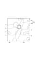
- FIG. 2 is a schematic diagram showing an example of a cross section of an electrode catalyst layer.
- the cross section of the electrode catalyst layer consists of a region R1 containing a catalyst material and a conductive carrier, and a region R2 not containing a catalyst material and a conductive carrier.
- the region R2 consists of a fibrous material 23 containing nitrogen atoms and a region n that does not contain the fibrous material 23 containing nitrogen atoms.
- the above specific area (observation area) is indicated by A and includes only area R2 and does not include area R1.
- the shape of the region (observation area) can be rectangular (including square), for example, a square of 150 nm x 150 nm.
- the fibrous material 23 containing nitrogen atoms may occupy 100% of the area in the specific region. There may be only one specific region in the cross section.
- the composition ratio of elements in a specific region can be measured, for example, by performing element mapping using a transmission electron microscope (TEM-EDX) equipped with an energy dispersive X-ray spectrometer.
- TEM-EDX transmission electron microscope
- the X-ray acceleration voltage in EDX is preferably 200 kV. By using such an accelerating voltage, it is possible to transmit an electron beam to a thickness of about nm in a specific region, and information on the fiber and the elements around the fiber can be obtained.
- a nitrogen atomic ratio of less than 2 at% means that the fiber density is too low.
- a nitrogen atomic ratio of more than 20 at% means that the density of the fibers is too high.
- a nitrogen atomic ratio of 2 at % to more than 20 at % in EDX analysis of a specific region means that the density of the fibers is appropriate.
- the density of the fibers is too low, the interaction between the nitrogen-containing fibers and ions such as sulfonic acid groups of the polymer electrolyte will be weakened, leading to a lack of proton conduction paths and a tendency to increase resistance. Furthermore, if the density of the fibers is too high, the intertwining or aggregation of the fibers may clog the voids, making it impossible to ensure sufficient drainage and gas diffusivity.
- the unshared electron pairs of the nitrogen atoms interact with the protons of the polymer electrolyte, improving the proton conductivity in the electrode catalyst layer and improving the output characteristics.
- the method for exposing the cross section is the same as the method for observing the thickness of the electrode catalyst layer 10 described below.
- the weight ratio of the fibrous substance 15 contained in the electrode catalyst layer 10 can be obtained by the ratio of the weight after removing substances other than the substance by chemical and electrochemical methods to the weight before removal.
- catalytic materials can be dissolved by acids such as aqua regia containing strong oxidizing agents, and conductive supports can be burnt out by high potentials.
- polymer electrolytes and polymer electrolyte membranes can be decomposed using hydrogen peroxide or the like.
- the average fiber diameter of the fibrous material 15 included in the electrode catalyst layer 10 according to the present embodiment is preferably 50 nm or more and 400 nm or less. By setting the fiber diameter within this range, it is possible to increase the voids 4 in the electrode catalyst layer 10 and to suppress a decrease in proton conductivity, making it possible to increase output. If the average fiber diameter of the fibrous material 15 is smaller than the above range, the fibrous material may block the voids and sufficient drainage and gas diffusivity may not be ensured. Since fibrous substances do not have electronic conductivity, the electronic conductivity decreases as the amount added increases. As the fiber diameter becomes smaller, the number of fibers increases and the surface area increases with the same added weight, so the above effect can be brought to a wider range of catalyst layers.
- the fibrous material it is preferable for the fibrous material to be thin.
- the size of voids that may naturally occur when aggregates of catalyst carrier particles aggregate to form an agglomerate is approximately 50 nm. Therefore, if the fiber diameter is 50 nm or less, the voids may be blocked, leading to a decrease in drainage performance. Furthermore, if the average fiber diameter of the fibrous material 15 is larger than the above range, conduction of electrons and protons by the conductive carrier 13 and the polymer electrolyte 14 may be inhibited, resulting in an increase in resistance.
- the fiber length of the fibrous material 15 is preferably 1 ⁇ m or more and 80 ⁇ m, more preferably 5 ⁇ m or more and 70 ⁇ m or less.
- the fiber diameter of the fibrous material 15 is determined by, for example, measuring the diameter of the fibrous material 15 whose cross section is exposed when the cross section of the electrode catalyst layer 10 is observed using a scanning electron microscope (SEM). You can get it by doing.
- SEM scanning electron microscope
- the fiber diameter of the fibrous material 15 can be obtained by measuring the diameter of a perfect circle fitted along the short axis.
- the average fiber diameter can be obtained by measuring the fiber diameters of the fibrous material 15 at a plurality of locations, for example, 20 locations, and averaging them arithmetic.
- the peak of the fiber diameter distribution of the nitrogen-containing fibrous material 15 contained in the electrode catalyst layer 10 is 150 nm or more and 250 nm or less. If the fiber diameter of the fibrous material is smaller than the above range, the voids may become narrow and sufficient drainage and gas diffusivity may not be ensured. In this case, water may remain in the electrode catalyst layer 10, which may promote a decrease in output and deterioration of the electrode catalyst layer. When the fiber diameter of the fibrous material is larger than the above range, the proton conduction path by the polymer electrolyte 14 and the electron conduction path by the conductive carrier 13 are blocked, and resistance may increase.
- FIG. 3 is an explanatory diagram of the fiber diameter distribution of the fibrous material.
- the graph is a histogram representing the frequency of the fibrous material contained in the electrode catalyst layer 10 for each fiber diameter, and represents the distribution of fiber diameters.
- histograms are used to view the distribution of quantitative data.
- a histogram is a graph created by dividing data into several classes, creating a frequency distribution table, and then plotting the data class on the horizontal axis and the number of data included in that class on the vertical axis.
- the histogram is created with a class width of 10 nm.
- the maximum value of the obtained fiber diameter is 298 nm and the minimum value is 102 nm
- the class width of the histogram is 10 nm
- the smallest class is "100 nm or more and less than 110 nm”
- the largest class is "290 nm or more”. "less than 300 nm”.
- the number of classes is 20.
- the peak of the fiber diameter distribution refers to the median value of the class with the highest frequency in the frequency distribution table and histogram. For example, in the histogram of the fiber diameters of the fibrous material contained in the electrode catalyst layer 10, when the frequency of the class of 200 nm or more and less than 210 nm is the highest, the peak of the fiber diameter distribution of the fibrous material is 205 nm.
- the fiber diameter of the fibrous material is determined by measuring the diameter of the exposed fibrous material when the cross section of the electrode catalyst layer 10 is observed using a scanning electron microscope (SEM), as shown in FIG. 4, for example. You can get it by lengthening it.
- SEM scanning electron microscope
- the exposed cross section may have an elliptical shape.
- the fiber diameter can be obtained by measuring the diameter of a perfect circle fitted along the short axis.
- the surface of the fibrous material rather than the cross section of the fibrous material may be exposed. In that case, the fiber diameter can be obtained by measuring the width of the fiber perpendicular to the long axis of the exposed fibrous material.
- a histogram representing the frequency of each fiber diameter can be obtained. The more locations the fiber diameter is measured, the more clearly the peak of the fiber diameter can be determined.
- the observation magnification with a scanning electron microscope (SEM) is preferably about 50,000 times or more, since this allows the outline of the fibrous material to be clearly confirmed and the fiber diameter to be accurately measured.
- a method for exposing the cross section of the electrode catalyst layer 10 known methods such as ion milling and ultramicrotome can be used, for example.
- cryo-ion milling is performed while cooling the electrode catalyst layer 10 in order to reduce damage to the polymer electrolyte membrane 11 and the polymer electrolyte 14 that constitutes the electrode catalyst layer 10. It is particularly preferable to use
- the thickness of the electrode catalyst layer 10 is preferably 30 ⁇ m or less. When the thickness is thicker than 30 ⁇ m, cracks are likely to occur, and when used in a fuel cell, the diffusibility and conductivity of gas and generated water decrease, resulting in a decrease in output.
- the thickness may be 10 ⁇ m or less.
- the thickness of the electrode catalyst layer 10 is preferably 2 ⁇ m or more. When the thickness is thicker than 10 ⁇ m, cracks are likely to occur, and when used in a fuel cell, the diffusivity and conductivity of gas and generated water decrease, resulting in a decrease in output.
- the thickness of the electrode catalyst layer 10 may be 5 ⁇ m or more.
- the thickness of the electrode catalyst layer 10 can be measured, for example, by observing a cross section of the electrode catalyst layer 10 using a scanning electron microscope (SEM).
- SEM scanning electron microscope
- known methods such as ion milling and ultramicrotome can be used.
- cryo-ion milling is performed while cooling the electrode catalyst layer 10 in order to reduce damage to the polymer electrolyte membrane 11 and the polymer electrolyte 14 that constitutes the electrode catalyst layer 10.
- the thickness of the electrode catalyst layer can be measured by measuring the length of the electrode catalyst layer within a field of view that covers the entire electrode catalyst layer at an observation magnification of about 1,000 times to 10,000 times. In order to ascertain the thickness evenly within the catalyst layer, it is preferable to measure in the same manner at at least 20 observation points.
- metals included in the platinum group metals other than the platinum group, alloys of these metals, oxides, double oxides, and carbides can be used.
- Metals included in the platinum group are platinum, palladium, ruthenium, iridium, rhodium, and osmium.
- metals other than platinum group metals include iron, lead, copper, chromium, cobalt, nickel, manganese, vanadium, molybdenum, gallium, and aluminum.
- a carrier that is electrically conductive and capable of supporting the catalyst substance 12 without being corroded by the catalyst substance 12 can be used.
- Carbon particles can be used for the conductive carrier 13.
- the particle size of the carbon particles is preferably about 10 nm or more and 1000 nm or less, and more preferably about 10 nm or more and 100 nm or less.
- the particle size is 10 nm or more, the carbon particles do not clog the electrode catalyst layer 10 too densely, thereby suppressing deterioration of the gas diffusivity of the electrode catalyst layer 10.
- the particle size of the carbon particles is a volume average diameter determined by a laser diffraction/scattering method.
- An electrolyte having proton conductivity can be used for the polymer electrolyte 14 included in the polymer electrolyte membrane 11 and the electrode catalyst layer 10.
- a fluorine-based polymer electrolyte and a hydrocarbon-based polymer electrolyte can be used as the polymer electrolyte.
- a polymer electrolyte having a tetrafluoroethylene skeleton can be used as the fluorine-based polymer electrolyte.
- An example of the polymer electrolyte having a tetrafluoroethylene skeleton is Nafion (registered trademark) manufactured by DuPont.
- hydrocarbon polymer electrolyte for example, sulfonated polyether ketone, sulfonated polyether sulfone, sulfonated polyether ether sulfone, sulfonated polysulfide, and sulfonated polyphenylene can be used.
- the polymer electrolyte contained in the polymer electrolyte membrane 11 and the polymer electrolyte 14 contained in the electrode catalyst layer 10 may be the same electrolyte or different electrolytes. However, when considering the interfacial resistance at the interface between the polymer electrolyte membrane 11 and the electrode catalyst layer 10 and the rate of dimensional change in the polymer electrolyte membrane 11 and the electrode catalyst layer 10 when the humidity changes, the polymer electrolyte membrane 11
- the polymer electrolyte contained in the electrode catalyst layer 10 and the polymer electrolyte 14 contained in the electrode catalyst layer 10 are preferably the same electrolytes or polymer electrolytes with similar coefficients of thermal expansion.
- FIG. 5 shows a configuration example of the membrane electrode assembly according to the present embodiment, in which (a) is a plan view of the membrane electrode assembly seen from the oxygen electrode side of the electrode catalyst layer 10, and (b) is the same as that of (a).
- FIG. 3 is a cross-sectional view taken along line XX'.
- the membrane electrode assembly 1 includes a polymer electrolyte membrane 11 and electrode catalyst layers 10C and 10A bonded to the front and back surfaces of the polymer electrolyte membrane 11, respectively.
- the electrode catalyst layer 10C formed on the upper surface (front surface) of the polymer electrolyte membrane 11 is a cathode side electrode catalyst layer that constitutes an oxygen electrode, and is formed on the lower surface (back surface) of the polymer electrolyte membrane 11.
- the electrode catalyst layer 10A is an anode side electrode catalyst layer that constitutes a fuel electrode.
- the pair of electrode catalyst layers 10C and 10A may be abbreviated as "electrode catalyst layer 10" if there is no need to distinguish them.
- the electrode catalyst layer 10 may be provided on at least one surface of the polymer electrolyte membrane 11.
- a gasket 16C on the oxygen electrode side and a gasket 16A on the fuel electrode side are arranged in the membrane electrode assembly 1. There is.
- a catalyst ink is prepared.
- a catalyst ink is prepared by mixing a catalyst material 12, a conductive carrier 13, a polymer electrolyte 14, and a fibrous material 15 in a dispersion medium, and then subjecting the mixture to a dispersion treatment.
- the dispersion treatment can be performed using, for example, a planetary ball mill, a bead mill, an ultrasonic homogenizer, or the like.
- the dispersion medium of the catalyst ink contains the polymer electrolyte 14 in a state that does not erode the catalyst material 12, the conductive carrier 13, the polymer electrolyte 14, and the fibrous material 15, and the dispersion medium has high fluidity. Any solvent that can dissolve or disperse the polyelectrolyte 14 as a fine gel can be used.
- the dispersion medium may contain water.
- the catalyst ink includes a volatile liquid organic solvent. Since there is a risk of ignition when the solvent is a lower alcohol, water is preferably mixed with such a solvent. Water can be mixed with the solvent within a range that does not cause the catalyst ink to become cloudy or gelatinous due to separation of the polymer electrolyte 14.
- the electrode catalyst layer 10 is formed on the base material.
- the polymer electrolyte membrane 11 or a transfer base material can be used as the base material.
- the electrode catalyst layer 10 is formed by directly applying catalyst ink to the surface of the polymer electrolyte membrane 11 and then removing the solvent from the coating film of the catalyst ink. A forming method can be used.
- the catalyst ink is directly applied to the opposite surface of the polymer electrolyte membrane 11 so as to face the electrode catalyst layer 10A with the polymer electrolyte membrane 11 in between, and then the solvent is removed from the catalyst ink coating.
- the electrode catalyst layer 10A can be formed and the membrane electrode assembly 1 can be obtained.
- a transfer base material a catalyst layer-coated base material is produced by applying catalyst ink onto the transfer base material and then drying it. Thereafter, for example, by heating and pressurizing the surface of the electrode catalyst layer 10 in the base material with the catalyst layer and the polymer electrolyte membrane 11 in contact with each other, the electrode catalyst layer 10 and the polymer electrolyte membrane 11 are brought into contact with each other. 11 are joined. By joining the electrode catalyst layers 10 to both sides of the polymer electrolyte membrane 11, the membrane electrode assembly 1 can be manufactured.
- the ratio of the number of nitrogen atoms to the total number of atoms of carbon, nitrogen, oxygen, fluorine, sulfur, and platinum elements obtained by energy dispersive X-ray spectroscopy of a specific region of the electrode catalyst layer is adjusted to the above range. For example, adjusting the fiber diameter of the nitrogen-containing fibers in the electrode catalyst layer, adjusting the amount of polymer electrolyte in the electrode catalyst layer, adjusting the amount of nitrogen-containing fibers in the electrode catalyst layer, etc. It can be prepared by
- the gas diffusion layer 17 with a catalyst layer is produced, for example, by applying catalyst ink to the surface of the gas diffusion layer 17 and then drying it. Thereafter, by heating and pressurizing the surface of the electrode catalyst layer 10 in the catalyst layer-equipped gas diffusion layer 17 and the polymer electrolyte membrane 11 in contact with each other, the electrode catalyst layer 10 and the polymer electrolyte membrane 11 are brought into contact with each other. to join. By joining the electrode catalyst layers 10 to both sides of the polymer electrolyte membrane 11, the membrane electrode assembly 1 can be manufactured.
- Various coating methods can be used to apply the catalyst ink to the base material.
- the coating method include die coating, roll coating, curtain coating, spray coating, and squeegee coating.
- die coating is preferable because the film thickness in the middle of the coating period is stable and intermittent coating is possible.
- a method for drying the coating film of the catalyst ink for example, drying using a hot air oven, drying using IR (far infrared rays), drying using a hot plate, drying under reduced pressure, etc. can be used.
- the drying temperature is 40°C or more and 200°C or less, preferably about 40°C or more and 120°C or less.
- the drying time is 0.5 minutes or more and 1 hour or less, preferably about 1 minute or more and 30 minutes or less.
- the pressure and temperature applied to the electrode catalyst layer 10 during transfer of the electrode catalyst layer 10 affect the power generation performance of the membrane electrode assembly 1.
- the pressure applied to the electrode catalyst layer 10 is preferably 0.1 MPa or more and 20 MPa or less. By setting the pressure to 20 MPa or less, the electrode catalyst layer 10 is prevented from being excessively compressed. By setting the pressure to 0.1 MP or more, it is possible to suppress a decrease in power generation performance due to a decrease in bonding between the electrode catalyst layer 10 and the polymer electrolyte membrane 11.
- the temperature at the time of bonding is determined based on the temperature of the polymer contained in the polymer electrolyte membrane 11 or the electrode catalyst layer 10, considering the improvement of the bondability of the interface between the polymer electrolyte membrane 11 and the electrode catalyst layer 10 and the suppression of interfacial resistance.
- the temperature is near the glass transition point of the electrolyte 14.
- a polymer film or a sheet formed of a fluororesin can be used as the transfer substrate.
- Fluorine resins have excellent transferability.
- fluororesins include ethylenetetrafluoroethylene copolymer (ETFE), tetrafluoroethylene-hexafluoropropylene copolymer (FEP), tetrafluoroperfluoroalkyl vinyl ether copolymer (PFA), and polytetrafluoroethylene copolymer (ETFE) Examples include fluoroethylene (PTFE).
- polymers that form polymer films include polyimide, polyethylene terephthalate, polyamide (nylon (registered trademark)), polysulfone, polyethersulfone, polyphenylene sulfide, polyether/etherketone, polyetherimide, and polyarylate. , and polyethylene naphthalate.
- a gas diffusion layer can also be used for the transfer base material.
- the electrode catalyst layer 10 can have sufficient gas diffusivity and proton conductivity.
- the blending ratio of the polymer electrolyte 14 in the electrode catalyst layer 10 is preferably about the same to about half the weight of the conductive carrier 13.
- the blending ratio of the fibrous substance 15 is preferably equal to or less than the weight of the conductive carrier 13. It is preferable that the solid content ratio of the catalyst ink be as high as possible within a range that can be applied to a thin film.
- the blending ratio of the fibrous material 15 containing nitrogen atoms in the electrode catalyst layer 10 is preferably approximately 1% by mass or more and 10% by mass or less. If the blending ratio of the fibrous material 15 containing nitrogen atoms in the electrode catalyst layer 10 is less than 1% by mass, the effect of reducing proton conduction resistance and improving gas diffusivity will not be sufficiently obtained, and the electrode catalyst layer Cracks may occur when forming 10, resulting in decreased durability during long-term operation. On the other hand, if the blending ratio of the fibrous material 15 in the electrode catalyst layer 10 is more than 10% by mass, the catalytic reaction may be inhibited and the battery performance may deteriorate. It is preferable that the solid content ratio of the catalyst ink be as high as possible within a range that can be applied to a thin film.
- FIG. 6 is an exploded perspective view showing a configuration example of a polymer electrolyte fuel cell 3 equipped with a membrane electrode assembly 1. As shown in FIG. Note that FIG. 6 shows an example of the configuration of a single cell, and the polymer electrolyte fuel cell 3 is not limited to this configuration, and may have a configuration in which a plurality of single cells are stacked.
- the polymer electrolyte fuel cell 3 includes a membrane electrode assembly 1, a gas diffusion layer 17C on the oxygen electrode side, and a gas diffusion layer 17A on the fuel electrode side.
- the gas diffusion layer 17C is disposed opposite to the electrode catalyst layer 10C, which is the cathode electrode catalyst layer on the oxygen electrode side of the membrane electrode assembly 1.
- the gas diffusion layer 17A is arranged to face the electrode catalyst layer 10A, which is the anode side electrode catalyst layer on the fuel electrode side of the membrane electrode assembly 1.
- the electrode catalyst layer 10C and the gas diffusion layer 17C constitute an oxygen electrode 2C
- the electrode catalyst layer 10A and the gas diffusion layer 17A constitute a fuel electrode 2A.
- a gasket 16C on the oxygen electrode side and a gasket 16A on the fuel electrode side are arranged.
- the polymer electrolyte fuel cell 3 includes a separator 18C arranged to face the oxygen electrode 2C, and a separator 18A arranged to face the fuel electrode 2A.
- the separator 18C has a gas flow path 19C for reactant gas flow formed on the surface facing the gas diffusion layer 17C, and a cooling water flow path formed on the surface opposite to the surface where the gas flow path 19C is formed.
- a water flow path 20C is provided.
- the separator 18A has the same configuration as the separator 18C, and includes a gas flow path 19A formed on a surface facing the gas diffusion layer 17A, and a surface opposite to the surface on which the gas flow path 19A is formed.
- the cooling water flow path 20A is formed in the cooling water flow path 20A.
- Separators 18C and 18A are made of an electrically conductive and gas impermeable material.
- an oxidizing agent such as air or oxygen is supplied to the oxygen electrode 2C through the gas flow path 19C of the separator 18C, and fuel containing hydrogen is supplied through the gas flow path 19A of the separator 18A. Gas or organic fuel is supplied to the fuel electrode 2A to generate electricity.
- the polymer electrolyte fuel cell 3 according to the present embodiment has sufficient drainage performance and gas diffusivity, and has high long-term power generation performance and high It becomes possible to demonstrate durability. That is, according to the present embodiment, the electrode has sufficient gas diffusivity and proton conductivity during operation of the polymer electrolyte fuel cell 3, and is capable of exhibiting high power generation performance and high durability over a long period of time.
- a catalyst layer 10, a membrane electrode assembly 1, and a polymer electrolyte fuel cell 3 can be provided. Therefore, the present disclosure can be suitably used for stationary cogeneration systems, fuel cell vehicles, etc. that utilize polymer electrolyte fuel cells, and has great industrial utility value.
- FIGS. 7 to 9 An embodiment of an electrode catalyst layer, a membrane electrode assembly, and a polymer electrolyte fuel cell will be described with reference to FIGS. 7 to 9. Each figure in the drawings is appropriately exaggerated to facilitate understanding. Furthermore, the configurations and materials of the electrode catalyst layer, membrane electrode assembly, polymer electrolyte fuel cell, and method for manufacturing the same according to the present embodiment are not limited to the configurations and materials described below, but are similar to those described below. Includes all materials and configurations that can be assumed to have functions.
- the membrane electrode assembly 100 includes a polymer electrolyte membrane 11, a cathode electrode catalyst layer 12C, and an anode electrode catalyst layer 12A.
- the polymer electrolyte membrane 11 is a solid polymer electrolyte membrane.
- the polymer electrolyte membrane 11 is made of, for example, a polymer material having proton conductivity.
- the polymer material having proton conductivity include fluororesins and hydrocarbon resins.
- fluororesins include Nafion (manufactured by DuPont, registered trademark), Flemion (manufactured by AGC, registered trademark), and Gore-Select (manufactured by Gore, registered trademark).
- Examples of the hydrocarbon resin include engineering plastics and engineering plastics into which sulfonic acid groups have been introduced.
- the cathode side electrode catalyst layer 12C is an electrode catalyst layer that constitutes an air electrode that is a cathode, and is bonded to one surface of the polymer electrolyte membrane 11.
- the cathode side electrode catalyst layer 12C is a layer for oxidizing protons transported through the polymer electrolyte membrane 11 with an oxidizing agent containing oxygen, and for receiving electrons from an external circuit.
- the anode-side electrode catalyst layer 12A is an electrode catalyst layer that constitutes a fuel electrode, which is an anode, and is bonded to the surface of the polymer electrolyte membrane 11 opposite to the surface to which the cathode-side electrode catalyst layer 12C is bonded.
- the anode side electrode catalyst layer 12A is a layer for separating fuel gas into protons and electrons. Moreover, below, it may be described as an electrode catalyst layer as a concept including the cathode side electrode catalyst layer 12C and the anode side electrode catalyst layer 12A.
- Both the cathode side electrode catalyst layer 12C and the anode side electrode catalyst layer 12A are first electrode catalyst layers.
- one of the cathode side electrode catalyst layer 12C and the anode side electrode catalyst layer 12A is the first electrode catalyst layer, and the other one is the second electrode catalyst layer. That is, at least one of the cathode side electrode catalyst layer 12C and the anode side electrode catalyst layer 12A is the first electrode catalyst layer. This provides the effect of improving power generation performance at high current densities of 1.5 A/cm 2 or more.
- the cathode side electrode catalyst layer 12C constituting the air electrode is used as the first electrode catalyst layer. It is preferable to have one electrode catalyst layer.
- the first electrode catalyst layer 20 includes catalyst-supported particles 21, a polymer electrolyte 22, and a fibrous material 23. Further, the first electrode catalyst layer 20 may contain, as an optional component, other known components contained in the electrode catalyst layer of a fuel cell.
- the catalyst supporting particles 21 include a catalyst 21a and a carrier 21b supporting the catalyst 21a.
- metals included in the platinum group metals other than the platinum group, or alloys, oxides, double oxides, and carbides thereof can be used.
- metals included in the platinum group include platinum, palladium, ruthenium, iridium, rhodium, and osmium.
- metals other than platinum group include gold, iron, lead, copper, chromium, cobalt, nickel, manganese, vanadium, molybdenum, gallium, and aluminum.
- platinum, gold, palladium, rhodium, ruthenium, and alloys thereof have high catalytic activity and are suitable.
- the catalyst 21a constituting the catalyst-supported particles 21 may be only one type of the above example, or may be a combination of two or more types.
- the average particle diameter of the catalyst 21a is, for example, preferably 0.5 nm or more and 20 nm or less, and more preferably 1 nm or more and 5 nm or less.
- the average particle diameter of the catalyst 21a is, for example, preferably 0.5 nm or more and 20 nm or less, and more preferably 1 nm or more and 5 nm or less.
- the carrier 21b a material is used that has conductivity, is not attacked by the catalyst 21a, and is capable of supporting the catalyst 21a.
- the substance constituting the carrier 21b include carbon materials such as carbon black, graphite, graphite, activated carbon, carbon nanotubes, carbon nanofibers, and fullerene, and metal oxides.
- the metal oxide may be, for example, tin oxide.
- the tin oxide may be doped with tungsten or niobium. Thereby, the conductivity of the carrier 21b can be improved. It is particularly preferable that the carrier 21b is a carbon material.
- the surface area of the carrier 21b can be increased and the catalyst 21a can be supported at a higher density than when other carriers are selected. Thereby, the catalytic activity per carrier 21b can be improved.
- the carrier 21b constituting the catalyst-supported particles 21 may be only one type of the above example, or may be a combination of two or more types.
- the specific surface area of the carrier 21b is preferably included in the range of 50 m 2 /g or more and 2000 m 2 /g or less, and more preferably included in the range of 100 m 2 /g or more and 1500 m 2 /g or less.
- the specific surface area of the carrier 21b is 50 m 2 /g or more
- the catalyst 21a is supported at a high density, thereby increasing the activity of the catalyst 21a.
- the specific surface area of the carrier 21b is set to 2000 m 2 /g or less, the amount of micropores that the carrier 21b has can be suppressed, so that gas diffusivity within the carrier 21b can be improved. This suppresses an increase in the mass transport resistance of the first electrode catalyst layer 20, and as a result, suppresses a decrease in the output characteristics of the fuel cell including the first electrode catalyst layer 20.
- the degree of graphitization of the carrier 21b is preferably in the range of 20% or more and 80% or less.
- the degree of graphitization of the carrier 21b is 20% or more, the loss of the carrier 21b due to operation and stop of the fuel cell is suppressed, and a decrease in the output characteristics of the fuel cell tends to be suppressed.
- the degree of graphitization of the carrier 21b is 80% or less, the supporting of the catalyst 21a is stable, and even if the fuel cell is continued to be used, an increase in the particle size of the catalyst 21a tends to be suppressed. As a result, a decrease in the activity of the catalyst 21a is suppressed, and a decrease in the output of the fuel cell tends to be suppressed.
- the shape of the carrier 21b is not particularly limited, and may be, for example, a particle shape or a fiber shape. Note that, from the viewpoint of smoothly transmitting electrons generated on the surface of the catalyst 21a to the outside of the system, the carrier 21b preferably has a shape capable of supporting the catalyst 21a on its outer surface.
- the average particle diameter of the carrier 21b is, for example, preferably 10 nm or more and 1000 nm or less, more preferably 10 nm or more and 100 nm or less.
- the average particle diameter of the carrier 21b is, for example, preferably 10 nm or more and 1000 nm or less, more preferably 10 nm or more and 100 nm or less.
- the catalyst-supported particles 21 may be provided with a hydrophobic coating.
- the particles carrying the catalyst 21a may be covered with a hydrophobic coating.
- the hydrophobic coating has a thickness sufficient to allow the reaction gas to pass through.
- the thickness of the hydrophobic film is preferably 40 nm or less. If it becomes thicker than this, the supply of reaction gas to the active sites may be inhibited.
- the hydrophobic coating is 40 nm or less, the reaction gas can sufficiently permeate through the hydrophobic coating, so that hydrophobicity can be imparted to the catalyst-supported particles.
- the thickness of the hydrophobic coating covering the catalyst-supported particles 21 is preferably such that it sufficiently repels generated water.
- the thickness of the hydrophobic film is preferably 2 nm or more.
- the hydrophobic film covering the catalyst-supporting particles 21 is formed, for example, from a fluorine-based compound having at least one polar group.
- the polar group include a hydroxyl group, an alkoxy group, a carboxyl group, an ester group, an ether group, a carbonate group, and an amide group. Due to the presence of the polar group, the fluorine-based compound can be immobilized on the outermost surface of the first electrode catalyst layer 20.
- the portion other than the polar group in the fluorine-based compound preferably has a structure consisting of fluorine and carbon because of its high hydrophobicity and chemical stability. However, the structure is not limited to this, as long as the hydrophobic coating has sufficient hydrophobicity and chemical stability.
- a substance having proton conductivity is used as the polymer electrolyte 22 .
- the substance having proton conductivity include fluorine-based polymer electrolytes and hydrocarbon-based polymer electrolytes.
- fluorine-based polymer electrolyte include those having a tetrafluoroethylene skeleton, such as Nafion (registered trademark) manufactured by DuPont.
- hydrocarbon polymer electrolyte include sulfonated polyether ketone, sulfonated polyether sulfone, sulfonated polyether ether sulfone, sulfonated polysulfide, and sulfonated polyphenylene.
- the polymer electrolyte 22 constituting the first electrode catalyst layer 20 may be of only one type of the above example, or may be a combination of two or more types.
- the polymer electrolyte 22 may have a proton donating group.
- proton-donating groups include sulfonic acid groups.
- the dry weight (equivalent weight EW) per mole of proton-donating group is preferably in the range of 600 g/mol or more and 1200 g/mol, and 700 g/mol or more and 1000 g/mol. It is more preferable to fall within the following range. When the equivalent weight EW is 600 g/mol or more, deterioration in power generation performance due to flooding tends to be suppressed.
- the dry weight is the weight measured after drying the polymer electrolyte 22 at 100° C. under reduced pressure for one day or more.
- the content of the polymer electrolyte in the first electrode catalyst layer 20 is preferably 40 parts by mass or more and 140 parts by mass or less, for example, when the content of the carrier 21b in the first electrode catalyst layer 20 is 100 parts by mass. .
- the content of the polymer electrolyte is preferably 40 parts by mass or more and 140 parts by mass or less, for example, when the content of the carrier 21b in the first electrode catalyst layer 20 is 100 parts by mass. .
- By setting the content of the polymer electrolyte to 40 parts by mass or more it is possible to suppress a decrease in proton conductivity due to loss of proton conduction paths. As a result, it becomes easy to ensure a balance between proton conductivity and electron conductivity in the first electrode catalyst layer 20.
- the catalyst 21a of the catalyst-supported particles 21 can be suitably exposed. As a result, the catalytic activity in the first electrode catalyst layer 20 is improved.
- the fibrous material 23 is preferably one that will not be affected by the catalyst 21a and the polymer electrolyte 22, and preferably hydrophilic carbon fibers and polymer fibers.
- the fibrous substance 23 makes it difficult for cracks to occur in the electrode catalyst layer, and the durability of the electrode catalyst layer increases.
- the hydrophilic carbon fiber include VGCF (Vapor Grown Carbon Fiber) and CNT (Carbon Nano Tube) which have been imparted with hydrophilicity.
- the fibrous material 23 may include a Lewis acidic or Lewis basic functional group in the molecular structure of the material. This makes it easier for the polymer electrolyte 22 to exist around the fibrous substance 23.
- a Lewis acidic functional group include hydrophilic carbon fibers and polymer fibers having hydroxyl groups, carbonyl groups, sulfonic acid groups, and phosphorous acid groups.
- Examples of the fibrous material 23 having a Lewis basic functional group include polymer fibers having an imide structure or an azole structure.
- Proton conductive sites such as sulfonyl groups contained in the polymer electrolyte 22 form hydrogen bonds with the Lewis acidic functional groups in the fibrous material 23, so that the polymer electrolyte 22 is formed around the fibrous material 23. It becomes easier to exist.
- acidic proton conductive sites such as sulfonyl groups contained in the polymer electrolyte 22 are bonded with acid bases, resulting in a high concentration around the fibrous material 23.
- Molecular electrolyte 22 is more likely to exist. Since acid-base bonds have a stronger bonding force than hydrogen bonds, the fibrous material 23 preferably contains a Lewis basic functional group.
- the fibrous substance 23 has an azole structure.
- the azole structure refers to a five-membered heterocyclic structure containing one or more nitrogen atoms, such as an imidazole structure and an oxazole structure.
- the substance containing a nitrogen atom preferably has a benzazole structure such as a benzimidazole structure or a benzoxazole structure.
- Specific examples of substances containing nitrogen atoms include polymers such as polybenzimidazole and polybenzoxazole.
- the shape of the fibrous material 23 is not particularly limited, and may have a hollow structure or a solid structure, for example. Note that the fibrous material 23 constituting the first electrode catalyst layer 20 may be of only one type in the above example, or may be a combination of two or more types.
- the ratio of the number of fluorine atoms to the total number of atoms of carbon, nitrogen, oxygen, fluorine, sulfur, and platinum elements, obtained by energy dispersive X-ray spectroscopy of a specific region of the cross section of the first electrode catalyst layer 20, is 0. It is 2 at% or more.
- a proton conduction path within the first electrode catalyst layer 20 is appropriately constructed.
- the first electrode catalyst layer 20 has excellent initial power generation performance from a low current density region to a high current density region.
- the ratio of fluorine atoms is preferably 0.3 at% or more, more preferably 0.4 at% or more.
- the ratio of fluorine atoms may be 1 at% or less.
- the above-mentioned specific region is a region that contains 50% by area or more of the fibrous material 23 and does not contain the catalyst-supported particles 21.
- FIG. 2 is a schematic diagram showing an example of a cross section of the first electrode catalyst layer.
- the cross section of the first electrode catalyst layer consists of a region R1 containing the catalyst-supporting particles 21 and a region R2 not including the catalyst-supporting particles 21.
- Region R2 consists of fibrous material 23 and region n that does not include fibrous material 23.
- the above-mentioned specific area (observation area) is indicated by A.
- the shape of the region (observation area) can be rectangular (including square), for example, a square of 150 nm x 150 nm.
- the fibrous material 23 may occupy 100% of the area in the specific region. There may be only one specific region in the cross section.
- a method for exposing the cross section of the first electrode catalyst layer 20 known methods such as ion milling and ultramicrotome can be used, for example.
- the processing is performed while cooling the first electrode catalyst layer 20 in order to reduce damage to the polymer electrolyte membrane 11 and the polymer electrolyte 22 that constitutes the first electrode catalyst layer 20. It is particularly preferred to use cryo-ion milling.
- the composition ratio of elements in a specific region can be measured, for example, by performing element mapping using a transmission electron microscope (TEM-EDX) equipped with an energy dispersive X-ray spectrometer.
- TEM-EDX transmission electron microscope
- the X-ray acceleration voltage in EDX is preferably 200 kV. With such an accelerating voltage, it is possible to transmit an electron beam to a thickness of about nm in a specific region, and information on the fibrous material 23 and the elements around it can be obtained.
- the polymer electrolyte 22 may cover at least a portion of the surface of the fibrous material 23. Thereby, the resulting membrane electrode assembly has improved durability and tends to exhibit high power generation characteristics even under low humidification conditions. It can be confirmed by the following method that the polymer electrolyte 22 covers at least a portion of the surface of the fibrous material 23. That is, a transmission electron microscope (TEM-EDX) equipped with an energy dispersive X-ray spectrometer or a scanning transmission microscope equipped with an energy dispersive X-ray spectrometer is used to examine a specific region of the cross section of the first electrode catalyst layer 20. Elemental mapping is performed using a type electron microscope (STEM-EDX).
- TEM-EDX transmission electron microscope
- STEM-EDX type electron microscope
- the element to be measured is at least one of fluorine atoms and atoms contained in the fibrous material 23.
- the boundary between the region where no atoms included in the fibrous material 23 are confirmed and the region where no atoms included in the fibrous material 23 are confirmed is defined as the surface of the fibrous material. If fluorine is confirmed within 10 nm from the surface of the fibrous material, it is determined that at least a portion of the surface of the fibrous material 23 is covered.
- the thickness of the polymer electrolyte 22 covering the fibrous material 23 may be the distance from the fluorine detected at the farthest position from the surface of the fibrous material 23 to the surface of the fibrous material 23.
- the thickness of the polymer electrolyte 22 covering the fibrous substance 23 is preferably 3 nm or more and 30 nm or less, more preferably 10 nm or more and 30 nm or less. When the thickness of the coating layer is within this range, protons can move on the fibrous material 23.
- the fibrous material 23 may have the ability to adsorb the polymer electrolyte 22. Since the polymer electrolyte 22 is adsorbed on the fibrous material 23, durability is improved with high mechanical properties such as suppressing the occurrence of cracks, and a proton conduction path is formed by the polymer electrolyte 22. , high power generation performance can be obtained. The fact that the polymer electrolyte 22 is adsorbed on the fibrous material 23 can be confirmed using a scanning transmission electron microscope (STEM-EDX) equipped with energy dispersive X-ray spectroscopy.
- STEM-EDX scanning transmission electron microscope
- the adsorption capacity of the fibrous substance 23 to the polymer electrolyte 22 is preferably 10 mg/g or more, more preferably 15 mg/g or more, and 30 mg/g or less, since the mechanical properties are improved. good.
- the adsorption ability of the fibrous material 23 to the polymer electrolyte 22 can be measured by the following method. That is, the fibrous material 23 is brought into contact with a dispersion liquid in which a predetermined concentration of the polymer electrolyte 22 is dispersed. The fibrous substance 23 is taken out from the dispersion liquid, and the dispersion liquid is filtered through a predetermined filter (eg, diameter 0.3 to 0.5 ⁇ m). Measure the concentration of polyelectrolyte contained in the filtrate. From the concentration, the amount of polymer electrolyte adsorbed per gram of fibrous material is calculated.
- a predetermined filter eg, diameter 0.3 to 0.5 ⁇ m
- the average fiber diameter of the fibrous material 23 is preferably included in the range of 10 nm or more and 500 nm or less, and more preferably included in the range of 10 nm or more and 300 nm or less. When the fiber diameter is within this range, the catalyst 21a can be brought close to each other inside the first electrode catalyst layer 20, and the fuel cell including the first electrode catalyst layer 20 can have a high output.
- the average fiber diameter of the fibrous material 23 can be measured by scanning electron microscopy (SEM) observation.
- the average fiber length of the fibrous material 23 is preferably within the range of 0.7 ⁇ m or more and 40 ⁇ m or less, and more preferably within the range of 2 ⁇ m or more and 30 ⁇ m or less.
- the average fiber length of the fibrous material 23 can be measured by SEM observation.
- the amount of water produced within the electrode catalyst layer as a result of a cell reaction is proportional to the amount of chemical reaction. Therefore, when power is generated at a high current density, the amount of generated water increases. If this generated water is not sufficiently drained out of the electrode catalyst layer, the generated water that remains in the electrode catalyst layer may block the gas diffusion path. In this case, flooding occurs, which is a phenomenon in which the reactant gas cannot reach the active sites and the power generation performance is significantly reduced.
- the fibrous substance 23 as a constituent material of the first electrode catalyst layer 20 an appropriate space is secured in the first electrode catalyst layer 20, and also has the aspect of promoting drainage of the generated water.
- the content of the fibrous substance 23 in the first electrode catalyst layer 20 is preferably 5 parts by mass or more and 20 parts by mass or less, and 5 parts by mass when the content of the carrier 21b in the first electrode catalyst layer 20 is 100 parts by mass.
- the amount is more preferably 10 parts by mass or less.
- the content of the fibrous substance 23 By setting the content of the fibrous substance 23 to 5 parts by mass or more, a network of the fibrous substances 23 is formed, making it easier to form the electrode catalyst layer. Thereby, it is possible to sufficiently construct a proton conduction path, an electron conduction path within the electrode catalyst layer, and to strengthen the structure of the electrode catalyst layer. As a result, the power generation performance of the fuel cell is improved.
- the content of the fibrous substance 23 By setting the content of the fibrous substance 23 to 20 parts by mass or less, an increase in resistance due to an increase in the thickness of the first electrode catalyst layer 20 can be suppressed.
- the density of the first electrode catalyst layer 20 is preferably contained within the range of 1000 mg/cm 3 or more and 5000 mg/cm 3 or less, and more preferably contained within the range of 1500 mg/cm 3 or more and 4000 mg/cm 3 or less. . Since the density of the first electrode catalyst layer 20 is 1000 mg/cm 3 or more, the amount of catalyst per unit volume is prevented from decreasing, and therefore the output of the fuel cell is prevented from decreasing. Furthermore, by setting the density of the first electrode catalyst layer 20 to 1000 mg/cm 3 or more, the distance between the polymer electrolyte 22 and the fibrous material 23 is suppressed from increasing, and the electrode catalyst layer 12 tends to be difficult to collapse. be.
- the durability of the first electrode catalyst layer 20 tends to improve.
- the density is 5000 mg/cm 3 or less
- the internal structure of the electrode catalyst layer 12 does not become too dense, and a decrease in drainage properties and gas diffusivity tends to be suppressed.
- the first electrode catalyst layer 20 tends to be able to suppress a decrease in output even when the output is high.
- the density is 5000 mg/cm 3 or less, it tends to be possible to suppress the bonding strength of the first electrode catalyst layer 20 from decreasing.
- the second electrode catalyst layer As the second electrode catalyst layer, a known electrode catalyst layer applied to membrane electrode assemblies can be used.
- the second electrode catalyst layer is, for example, an electrode that is different from the first electrode catalyst layer 20 in that it does not contain hydrophilic carbon fibers or high molecular weight polymer fibers, and has the same structure as the first electrode catalyst layer 20 in other respects. Examples include a catalyst layer.
- the materials used for the cathode side electrode catalyst layer 12C and the materials used for the anode side electrode catalyst layer 12A may be the same or at least partially different.
- the ratio (T2/T1) of the average thickness T2 of the anode side electrode catalyst layer 12A to the average thickness T1 of the cathode side electrode catalyst layer 12C is preferably 1.0 times or more and 2.0 times or less.
- T2/T1 is 1.0 times or more, the thickness of the catalyst layer becomes larger than that of the cathode side electrode catalyst layer 12C, and the volume of water that can be held increases. In that case, the diffusion of water generated in the cathode electrode catalyst layer 12C to the anode electrode catalyst layer 12A may be promoted, and the gas diffusion resistance in the cathode electrode catalyst layer 12C may be reduced. This tends to improve the output of the fuel cell.
- the thickness of the cathode side electrode catalyst layer 12C may become small, and the mechanical strength of the membrane electrode assembly 100 may become small.
- the polymer electrolyte membrane 11 may rupture from the cathode side, and the fuel cell may become inoperable.
- polymer electrolyte fuel cell Next, the configuration of a polymer electrolyte fuel cell including the membrane electrode assembly 100 will be explained. In the following, a single cell polymer electrolyte fuel cell will be described as an example of a polymer electrolyte fuel cell.
- the polymer electrolyte fuel cell is not limited to the configuration of a single cell, but may include a plurality of single cells, and may have a configuration in which the plurality of single cells are stacked.
- the polymer electrolyte fuel cell 30 includes a membrane electrode assembly 100, a pair of gas diffusion layers 31a, 31b, and a pair of separators 32a, 32b.
- the gas diffusion layers 31a and 31b are layers for uniformly diffusing the reaction gas.
- the gas diffusion layer 31a is arranged to face the cathode side electrode catalyst layer 12C of the membrane electrode assembly 100.
- the gas diffusion layer 31b is arranged to face the anode side electrode catalyst layer 12A of the membrane electrode assembly 100.
- the pair of gas diffusion layers 31a and 31b sandwich the membrane electrode assembly 100 in the thickness direction of the membrane electrode assembly 100.
- the cathode side electrode catalyst layer 12C and the gas diffusion layer 31a form an air electrode which is a cathode.
- the anode side electrode catalyst layer 12A and the gas diffusion layer 31b form a fuel electrode which is an anode.
- the gas diffusion layers 31a and 31b are made of a material that has electron conductivity and gas diffusivity.
- a porous carbon material can be used as the material constituting the gas diffusion layers 31a and 31b.
- the porous carbon material include carbon cloth, carbon paper, and nonwoven fabric.
- the separators 32a and 32b are members that play the role of extracting electrons to an external circuit, and are arranged outside the gas diffusion layer 31b.
- the pair of separators 32a and 32b sandwich the membrane electrode assembly 100 and the pair of gas diffusion layers 31a and 31b in the thickness direction of the membrane electrode assembly 100.
- the separators 32a, 32b have gas channels 33a, 33b and cooling water channels 34a, 34b.
- the gas flow paths 33a and 33b are flow paths for flowing a reaction gas, and are formed on the surfaces of the separators 32a and 32b that face the gas diffusion layers 31a and 31b.
- the cooling water channels 34a, 34b are channels for circulating cooling water, and are formed on the surface of the separators 32a, 32b opposite to the surface facing the gas diffusion layers 31a, 31b.
- the separators 32a and 32b are made of a material that is electrically conductive and impermeable to gas.
- materials constituting the separators 32a and 32b include carbon materials and metal materials. Further, it is preferable that the material constituting the separators 32a and 32b has a certain degree of strength and good moldability.
- Oxidizing gas as a reactive gas is supplied to the gas flow path 33a of the separator 32a facing the gas diffusion layer 31a constituting the air electrode.
- the oxidant gas is, for example, air or oxygen gas.
- a fuel gas as a reaction gas is supplied to the gas flow path 33b of the separator 32b facing the gas diffusion layer 31b constituting the fuel electrode.
- the fuel gas is, for example, hydrogen gas.
- a fuel gas containing hydrogen is supplied to the fuel electrode, and an oxidant gas containing oxygen is supplied to the air electrode, so that the following equations 1 and 2 are satisfied at the fuel electrode and the air electrode.
- the electrode reaction shown below occurs and electricity is generated.
- the polymer electrolyte fuel cell is used in combination with accompanying devices such as a gas supply device and a cooling device.
- Fuel electrode H 2 ⁇ 2H + +2e-...
- Air electrode 1/2O 2 +2H + +2e - ⁇ H 2 O...
- Form 2 [Method for manufacturing membrane electrode assembly]
- the method for manufacturing the membrane electrode assembly 100 includes a preparation step of preparing a catalyst ink, and a formation step of forming an electrode catalyst layer using the catalyst ink. (Preparation process) In the preparation step, a catalyst ink is prepared by mixing each component constituting the electrode catalyst layer using a dispersion medium.
- the dispersion medium is not particularly limited as long as it can disperse each component constituting the electrode catalyst layer.
- the dispersion medium include water, alcohol, ketones, or mixtures thereof. Specifically, water, alcohols such as methanol, ethanol, 1-propanol, 2-propanol, 1-butanol, 2-butanol, isobutyl alcohol, tert-butyl alcohol, acetone, methyl ethyl ketone, methyl propyl ketone, methyl Ketones such as butyl ketone, methyl isobutyl ketone, methyl amyl ketone, pentanone, heptanone, cyclohexanone, methyl cyclohexanone, acetonylacetone, diethyl ketone, dipropyl ketone, and diisobutyl ketone can be used as appropriate.
- alcohols such as methanol, ethanol, 1-propanol, 2-propanol,
- the catalyst ink may contain a dispersant for well dispersing each component constituting the electrode catalyst layer.
- the dispersant include anionic surfactants, cationic surfactants, amphoteric surfactants, and nonionic surfactants.
- anionic surfactants include alkyl ether carboxylates, ether carboxylates, alkanoyl sarcosine, alkanoyl glutamates, acyl glutamates, oleic acid/N-methyltaurine, potassium oleate/diethanolamine salts, alkyl ether sulfates, Triethanolamine salt, polyoxyethylene alkyl ether sulfate triethanolamine salt, amine salt of specially modified polyether ester acid, amine salt of higher fatty acid derivative, amine salt of specially modified polyester acid, amine of high molecular weight polyether ester acid Salt, amine salt of special modified phosphoric acid ester, amide amine salt of high molecular weight polyester acid, amide amine salt of special fatty acid derivative, alkyl amine salt of higher fatty acid, amide amine salt of high molecular weight polycarboxylic acid, sodium laurate, sodium stearate, olein carboxylic acid type surfactants such as sodium acid
- Sulfate ester type surfactant (mono or di)alkyl phosphate, (mono or di)alkyl phosphate, (mono or di)alkyl phosphate, alkyl polyoxyethylene phosphate, alkyl ether phosphate, alkyl poly Ethoxy phosphate, polyoxyethylene alkyl ether, alkylphenyl phosphate polyoxyethylene salt, alkylphenyl ether phosphate, alkylphenyl polyethoxy phosphate, polyoxyethylene alkylphenyl ether phosphate, higher alcohol phosphorus
- phosphate ester type surfactants such as acid monoester disodium salt, higher alcohol phosphoric acid diester disodium salt, and zinc dialkyldithiophosphate.
- cationic surfactants include benzyldimethyl ⁇ 2-[2-(P-1,1,3,3-tetramethylbutylphenoxy)ethoxy]ethyl ⁇ ammonium chloride, octadecylamine acetate, and tetradecylamine acetate.
- amphoteric surfactants include dimethyl palm betaine, dimethyl lauryl betaine, sodium lauryl aminoethylglycine, sodium lauryl aminopropionate, stearyl dimethyl betaine, lauryl dihydroxyethyl betaine, amidobetaine, imidazolinium betaine, lecithin, 3- Examples include sodium [ ⁇ -fluoroalkanoyl-N-ethylamino]-1-propanesulfonate and N-[3-(perfluorooctanesulfonamido)propyl]-N,N-dimethyl-N-carboxymethylene ammonium betaine.
- nonionic surfactants include coconut fatty acid diethanolamide (1:2 type), coconut fatty acid diethanolamide (1:1 type), bovine fatty acid diethanolamide (1:2 type), and bovine fatty acid diethanolamide (1:2 type).
- 1 type oleic acid diethanolamide (1:1 type), hydroxyethyl laurylamine, polyethylene glycol laurylamine, polyethylene glycol coconut, polyethylene glycol stearylamine, polyethylene glycol tallow amine, polyethylene glycol tallow propylene diamine, polyethylene glycol dioleylamine , dimethyl lauryl amine oxide, dimethyl stearyl amine oxide, dihydroxyethyl lauryl amine oxide, perfluoroalkyl amine oxide, polyvinyl pyrrolidone, higher alcohol ethylene oxide adduct, alkylphenol ethylene oxide adduct, fatty acid ethylene oxide adduct, polypropylene glycol ethylene oxide adduct
- Examples include fatty acid esters
- sulfonic acid type surfactants such as alkylbenzene sulfonic acid, oil-soluble alkylbenzene sulfonic acid, ⁇ -olefin sulfonic acid, sodium alkylbenzene sulfonate, oil-soluble alkylbenzene sulfonate, ⁇ -olefin sulfonate, etc.
- the agent can be suitably used as a dispersant because it has an excellent carbon dispersion effect and the catalyst performance is unlikely to change due to residual dispersant.
- the dispersion method in the preparation step is not particularly limited as long as it can disperse each component contained in the catalyst ink, and any known dispersion method can be used.
- Known dispersion methods include, for example, methods using a planetary ball mill, a bead mill, or an ultrasonic homogenizer.
- the blending ratio of each component and dispersion medium in the catalyst ink can be selected as appropriate depending on the coatability and required power generation performance.
- the catalyst ink obtained in the preparation step is applied to a base material, and then a drying process is performed to volatilize the dispersion medium, thereby forming a film-like electrode catalyst layer.
- a base material the polymer electrolyte membrane 11, a transfer base material, or the gas diffusion layers 31a and 31b can be used.
- the coating method when applying the catalyst ink to the substrate is not particularly limited, and any known coating method that is applied when coating a slurry-like mixture onto the substrate with a uniform film thickness may be used.
- Known coating methods include, for example, die coating, bar coating, spray coating, dipping, and screen printing. Among these, it is preferable to use the die coating method because the viscosity range of the catalyst ink that can be applied is relatively wide and the coating can be applied with high uniformity of film thickness.
- the drying method used for the drying process is not particularly limited as long as it is a method that can volatilize the dispersion medium, and known drying methods such as an oven, a hot plate, a method using far infrared rays, etc. can be used. . Further, the drying temperature and drying time in the drying process can be appropriately selected depending on the materials used for the electrode catalyst layer and the base material.
- a transfer base material is used as the base material
- a process is performed to transfer the electrode catalyst layer formed on the transfer base material from the transfer base material to the polymer electrolyte membrane 11.
- a transfer method using thermocompression bonding can be used.
- the transfer base material is not particularly limited as long as it can release the formed electrode catalyst layer and transfer it to the polymer electrolyte membrane.
- a fluororesin film can be used as the transfer base material. Fluororesin films have excellent transferability. Examples of the fluororesin constituting the fluororesin film include ethylenetetrafluoroethylene copolymer (ETFE), tetrafluoroethylene-hexafluoropropylene copolymer (FEP), and tetrafluoroperfluoroalkyl vinyl ether copolymer ( PFA) and polytetrafluoroethylene (PTFE).
- ETFE ethylenetetrafluoroethylene copolymer
- FEP tetrafluoroethylene-hexafluoropropylene copolymer
- PFA tetrafluoroperfluoroalkyl vinyl ether copolymer
- PTFE polytetrafluoroethylene
- the membrane electrode assembly 100 is obtained by providing electrode catalyst layers on both sides of the polymer electrolyte membrane 11. Then, the polymer electrolyte fuel cell 30 is obtained by stacking the obtained membrane electrode assembly 100, gas diffusion layers 31a, 31b, and separators 32a, 32b.
- gas diffusion A membrane electrode assembly 100 having layers 31a and 31b is obtained. Then, by laminating separators 32a and 32b on the obtained membrane electrode assembly 100, a polymer electrolyte fuel cell 30 is obtained.
- the manufacturing method of the electrode catalyst layer when manufacturing the cathode side electrode catalyst layer 12C and the manufacturing method of the electrode catalyst layer when manufacturing the anode side electrode catalyst layer 12A may be the same or different. It's okay.
- Example 1A1 a membrane electrode assembly according to an example based on the present disclosure will be described.
- a platinum-supported carbon catalyst (TEC10E50E, manufactured by Tanaka Kikinzoku Kogyo Co., Ltd.), water, 1-propanol, a polymer electrolyte (20% Nafion (registered trademark) dispersion liquid, manufactured by Wako Pure Chemical Industries, Ltd.), and nitrogen atoms were combined.
- the fibrous material contained therein (polyazole fiber, average fiber diameter 100-400 nm, peak of average fiber diameter distribution 210 nm) was mixed. This mixture was subjected to a dispersion treatment using a planetary ball mill at 300 rpm for 60 minutes.
- a zirconia ball having a diameter of 5 mm was added to about one third of the zirconia container.
- the weight of the polymer electrolyte is 100% by weight relative to the weight of the carbon support in the platinum-supported carbon catalyst, and the weight of the fibrous material containing nitrogen atoms is relative to the weight of the carbon support in the platinum-supported carbon catalyst.
- a catalyst ink was prepared by adjusting the concentration of water in the dispersion medium to 10% by weight, the proportion of water in the dispersion medium to 50% by weight, and the solid content concentration to 10% by weight.
- a coating film was formed by applying the catalyst ink to one side of a polymer electrolyte membrane (Nafion (registered trademark) 211, manufactured by DuPont) using a slit die coater to a thickness of 200 ⁇ m.
- a polymer electrolyte membrane Nafion (registered trademark) 211, manufactured by DuPont
- the polymer electrolyte membrane on which the coating film was formed was dried in a hot air oven at 80° C. until the coating film became tack free, thereby forming a cathode side electrode catalyst layer.
- a coating film was formed by applying catalyst ink to the opposite surface of the polymer electrolyte membrane using a slit die coater to a thickness of 50 ⁇ m.
- Example 1A1 The nitrogen element composition ratio in the catalyst layer was 12%.
- Example 1A2 When preparing the catalyst ink, the amount of the fibrous material containing nitrogen atoms was twice that of Example 1A1 (20% by weight relative to the weight of the carbon support), but in the same manner as in Example 1A1. , a membrane electrode assembly of Example 1A2 was obtained. The nitrogen element composition ratio in the catalyst layer was 20%.
- Example 1A3 The same method as in Example 1A2 was used, except that when preparing the catalyst ink, the amount of the fibrous material containing nitrogen atoms was 1/2 that of Example 1A1 (5% by weight based on the weight of the carbon carrier). Thus, a membrane electrode assembly of Example 1A3 was obtained. The nitrogen element composition ratio in the catalyst layer was 2%.
- Example 1A1 The same method as Example 1A1 was used, except that carbon nanofibers (VGCF-H (registered trademark), manufactured by Showa Denko Packaging) were added instead of the fibrous material containing nitrogen atoms when preparing the catalyst ink. A membrane electrode assembly of Comparative Example 1A1 was obtained. The nitrogen element composition ratio in the catalyst layer was 0%.
- Example 1A2 The same method as in Example 1A1 was used, except that when preparing the catalyst ink, the amount of the fibrous material containing nitrogen atoms was 1/10 of that in Example 1A1 (1% by weight relative to the weight of the carbon carrier). A membrane electrode assembly of Comparative Example 1A2 was obtained. The nitrogen element composition ratio in the catalyst layer was 0.8%.
- Comparative Example 1A3 When preparing the catalyst ink, the amount of the fibrous material containing nitrogen atoms was three times that of Example 1A1 (30% by weight relative to the weight of the carbon support), but in the same manner as in Example 1A1. , a membrane electrode assembly of Comparative Example 1A3 was obtained. The nitrogen element composition ratio in the catalyst layer was 21%.
- Example 1B1 In Example 11, a platinum-supported carbon catalyst (TEC10E50E, manufactured by Tanaka Kikinzoku Kogyo Co., Ltd.), water, 1-propanol, a polymer electrolyte (Nafion (registered trademark) dispersion, manufactured by Wako Pure Chemical Industries, Ltd.), and a fibrous material 15 ( Polyazole fibers, average fiber diameter 200 nm, fiber diameter distribution peak 205 nm, average fiber length approximately 20 ⁇ m) were mixed. This mixture was subjected to a dispersion treatment at 500 rpm for 60 minutes using a planetary ball mill (P-7 manufactured by Fritsch).
- TEC10E50E manufactured by Tanaka Kikinzoku Kogyo Co., Ltd.
- water 1-propanol
- a polymer electrolyte Nafion (registered trademark) dispersion, manufactured by Wako Pure Chemical Industries, Ltd.
- a fibrous material 15 Polyazole fibers, average fiber diameter 200 nm, fiber
- a zirconia ball having a diameter of 5 mm was added to about one third of the zirconia container.
- the mass of the polymer electrolyte is 100% by mass relative to the mass of the carbon particles, the mass of the fibrous substance in the solid content is 1% by mass, the proportion of water in the dispersion medium is 50% by mass, and the solid content concentration is 10% by mass.
- a catalyst ink was prepared by adjusting the percentage by mass.
- a coating film was formed by applying the catalyst ink to one side of a polymer electrolyte membrane (Nafion (registered trademark) 211, manufactured by DuPont) using a slit die coater to a thickness of 100 ⁇ m.
- a polymer electrolyte membrane Nafion (registered trademark) 211, manufactured by DuPont
- the polymer electrolyte membrane on which the coating film was formed was dried in a hot air oven at 80° C. until the coating film became tack free, thereby forming a cathode side electrode catalyst layer.
- a coating film was formed by applying catalyst ink to the opposite surface of the polymer electrolyte membrane using a slit die coater to a thickness of 50 ⁇ m.
- Example 1B1 the membrane electrode assembly 1 of Example 1B1 was obtained.
- Example 1B2 A membrane electrode assembly of Example 1B2 was obtained in the same manner as Example 1B1 except that polyazole fibers having a fiber diameter distribution peak of 195 nm were used.
- Example 1B3 A membrane electrode assembly of Example 1B3 was obtained in the same manner as Example 1B1 except that polyazole fibers having a fiber diameter distribution peak of 225 nm were used.
- Example 1B4 A membrane electrode assembly of Example 1B4 was obtained in the same manner as Example 1B1 except that polyazole fibers having a fiber diameter distribution peak of 215 nm were used.
- Example 1B5 A membrane electrode assembly of Example 1B5 was obtained in the same manner as in Example 1B1 except that polyazole fibers having a fiber diameter distribution peak of 205 nm were used.
- Example 1B6 A membrane electrode assembly of Example 1B6 was obtained in the same manner as in Example 1B1, except that polyazole fibers having a fiber diameter distribution peak of 185 nm were used.
- Example 1B7 A catalyst ink was prepared by a method similar to Example 1B6.
- a coating film was formed by applying the catalyst ink to a thickness of 100 ⁇ m on the surface of a PTFE film using a slit die coater.
- the PTFE film on which the coating film was formed was dried in a hot air oven at 80° C. until the coating film became tack free, thereby obtaining a transfer base material with a cathode side electrode catalyst layer.
- a coating film was formed by applying the catalyst ink to the surface of another PTFE film using a slit die coater to a thickness of 50 ⁇ m.
- the PTFE film on which the coating film was formed was dried in a hot air oven at 80° C. until the tack of the coating film disappeared, thereby obtaining a transfer base material with an anode side electrode catalyst layer.
- a transfer base material with a cathode side electrode catalyst layer and a transfer base material with an anode side electrode catalyst layer are placed on the front and back surfaces of a polymer electrolyte membrane (Nafion (registered trademark) 211, manufactured by Dupont) so that they face each other. were arranged to form a laminate.
- the laminate was hot-pressed at 120° C. and 1 MPa to bond electrode catalyst layers to the front and back surfaces of the polymer electrolyte membrane, respectively.
- the membrane electrode assembly of Example 1B7 was obtained by peeling off the PTFE film from each electrode catalyst layer.
- Example 1B8 A membrane electrode assembly of Comparative Example 1B8 was obtained in the same manner as in Example 1B1, except that polyazole fibers having a fiber diameter distribution peak of 295 nm were used.
- Comparative Example 1B1 A membrane electrode assembly of Comparative Example 1B1 was obtained in the same manner as in Example 1B1, except that polyazole fibers were not added when preparing the catalyst ink.
- Comparative Example 1B2 was prepared in the same manner as in Example 1B1, except that carbon nanofibers (VGCF (registered trademark)-H, manufactured by Showa Denko K.K.) were added instead of polyazole fibers when preparing the catalyst ink. A membrane electrode assembly was obtained.
- VGCF registered trademark
- the fiber diameter distribution peak was measured by observing the cross section of the membrane electrode assembly using a scanning electron microscope (SEM). Specifically, first, a small piece of the membrane electrode assembly 1 was adhered to a metal plate, and the cross section of the electrode catalyst layer was exposed using a cross-sectional sample preparation device IB-19520CCP manufactured by JEOL. Next, the exposed cross section was observed using FE-SEM S-4800 manufactured by Hitachi High Technology Co., Ltd. at an observation magnification of 50,000 times, and the fiber diameter of the polymer fiber within the field of view was measured using a circle diameter measuring function. If the fiber was cut diagonally, the diameter of the fitted circle was measured along the short axis.
- SEM scanning electron microscope
- the width of the fiber perpendicular to the long axis of the exposed fiber was measured. This was carried out at a plurality of observation points evenly within the catalyst layer, and a data group of fiber diameters of 30 polymer fibers was obtained. Using this data group, a frequency distribution table was created with a class width of 10 nm, and a histogram representing the fiber diameter distribution was obtained. The median value of the class with the highest frequency in the histogram was obtained as the peak of the fiber diameter distribution of the polymer fibers.
- the ratio of the number of nitrogen atoms to the total number of atoms of carbon, nitrogen, oxygen, fluorine, sulfur, and platinum elements was measured by energy dispersive X-ray spectroscopy of a specific region of the electrode catalyst layer. Specifically, first, a cross section of the electrode catalyst layer was obtained using cryo-ion milling, which processes the electrode catalyst layer while cooling it. Next, using a transmission electron microscope (TEM-EDX) equipped with energy-dispersive I calculated it. The accelerating voltage was 200 kV.
- the specific area has a size of 150 nm x 150 nm, and is an area in which the fibrous material containing nitrogen atoms occupies 50% or more of the area of the visual field.
- Table 1 shows the conditions and results of each example and comparative example.
- the nitrogen atomic ratio in the electrode catalyst layer was 2% or more and 20% by weight or less.
- the power generation performance and durability A and B were both rated "A". That is, in Examples 1A and 1B, membrane electrode assemblies capable of forming fuel cells with excellent power generation performance and durability were obtained.
- the nitrogen atomic percentage in the electrode catalyst layer was outside the range of 2 at % or more and 20 at % or less.
- power generation performance and durability A and B at least one of them was rated "B". That is, when the nitrogen element composition ratio in the electrode catalyst layer was outside the above range, at least one of power generation performance and durability decreased.
- the nitrogen element composition ratio in the electrode catalyst layer is 2 at% or more and 20 at% or less, a membrane electrode assembly that can constitute a fuel cell with even better power generation performance can be obtained.
- the properties were particularly improved in the examples in which the fiber diameter distribution of the polymer fibers had a peak of 150 nm or more and 250 nm or less.
- Example 2A1 A catalyst ink was prepared by carrying out a dispersion treatment on a liquid mixture of catalyst-supported particles, a polymer electrolyte, a fibrous material, and a dispersion medium.
- the blending amount of the polymer electrolyte was set to be 70 parts by mass with respect to 100 parts by mass of the carrier contained in the catalyst-supporting particles.
- the amount of the fibrous material was 5 parts by mass based on 100 parts by mass of the carrier contained in the catalyst-supported particles.
- the blending amount of the dispersion medium was such that the solid content concentration of the catalyst ink was 10% by mass.
- the dispersion treatment was carried out for 60 minutes at a rotation speed of 600 rpm using zirconia balls with a diameter of 3 mm and a planetary ball mill. Details of each component used in the catalyst ink are as follows.
- Catalyst-supported particles platinum-supported carbon catalyst (support density 50% by mass)
- Polymer electrolyte Fluorine-based polymer electrolyte (manufactured by Wako Pure Chemical Industries, Ltd., Nafion (registered trademark) dispersion, contains proton-donating groups, dry weight per mole of proton-donating groups: 1100 g/mol)
- Fibrous substance azole structure-containing polymer fiber (average fiber diameter 300 nm x average fiber length 10 ⁇ m)
- the prepared catalyst ink was applied to the surface of the polymer electrolyte membrane opposite to the surface on which the cathode side electrode catalyst layer was formed, thereby forming a rectangular coating film measuring 50 mm in length and 50 mm in width. .
- the amount of catalyst ink applied was such that the amount of platinum supported was 0.1 mg/cm 2 .
- a drying process was performed using an oven at 80° C. to volatilize the dispersion medium contained in the coating film to form an anode-side electrode catalyst layer, thereby obtaining a membrane electrode assembly.
- Example 2A2 The same method as Example 2A1 was used, except that when preparing the catalyst slurry, the amount of the fibrous material was 20 parts by mass based on 100 parts by mass of the carrier contained in the catalyst-supported particles. A membrane electrode assembly was obtained.
- Example 2A1 The same method as Example 2A1 was used, except that when preparing the catalyst slurry, the amount of the fibrous material was 30 parts by mass based on 100 parts by mass of the carrier contained in the catalyst-supported particles. A membrane electrode assembly was obtained.
- Comparative example 2A2 A membrane electrode assembly was obtained in the same manner as in Example 2A1, except that the type of fibrous material was changed. Details of the fibrous material used in Comparative Example 2A2 are as follows.
- Fibrous substance non-hydrophilized carbon fiber (VGCF-H (registered trademark) manufactured by Showa Denko, average fiber length 6 ⁇ m, average fiber diameter 150 nm)
- Comparative example 2A3 The same method as Comparative Example 2A2 except that the amount of the fibrous material was 20 parts by mass per 100 parts by mass of the carrier contained in the catalyst-supported particles when preparing the catalyst slurry. A membrane electrode assembly was obtained.
- Comparative example 2A4 The same method as Comparative Example 2A2 except that when preparing the catalyst slurry, the amount of the fibrous material was 30 parts by mass based on 100 parts by mass of the carrier contained in the catalyst-supported particles. An electrode assembly was obtained.
- Example 2B1 100 mg of catalyst-supported particles (platinum-supported carbon, trade name: "TEC10E50E”, manufactured by Tanaka Kikinzoku Kogyo Co., Ltd., platinum amount: 50 mg, carbon amount: 50 mg) and 5 mg of fibrous material (polymer containing an azole structure) Polymer fibers (average fiber diameter 300 nm x average fiber length 10 ⁇ m) were placed in a container. 1.0 g of water was added to the container and mixed, and then a dispersion liquid (manufactured by Fuji Film Wako Pure Chemical Industries, Ltd.) was added to the container and stirred.
- TEC10E50E platinum amount: 50 mg
- carbon amount 50 mg
- fibrous material polymer containing an azole structure
- the dispersion contains 1.0 g of 1-propanol and 60 mg of polyelectrolyte (Nafion®, containing proton-donating groups, dry weight per mole of proton-donating groups: 1100 g/mol). Thereby, a catalyst slurry was obtained. A catalyst slurry was applied to both sides of a polymer electrolyte membrane by die coating and dried to obtain a membrane electrode assembly.
- Example 2B2 A membrane electrode assembly was obtained in the same manner as in Example 2B1, except that hydrophilic carbon fibers (average fiber diameter 150 nm x average fiber length 30 ⁇ m) were used as the fibrous material when preparing the catalyst slurry.
- hydrophilic carbon fibers average fiber diameter 150 nm x average fiber length 30 ⁇ m
- Example 2B3 A membrane electrode assembly was obtained in the same manner as in Example 2B1, except that the amount of the azole structure-containing polymer fiber was 15 mg when preparing the catalyst slurry.
- Example 2B4 A membrane electrode assembly was obtained in the same manner as in Example 2B1, except that the amount of the azole structure-containing polymer fiber was 0.5 mg when preparing the catalyst slurry.
- Example 2B5 When preparing the catalyst slurry, as a dispersion liquid, 1.0 g of 1-propanol and 70 mg of polymer electrolyte (Nafion (registered trademark), containing a proton-donating group, dry weight per mole of proton-donating group: 1300 g A membrane electrode assembly was obtained in the same manner as in Example 2B1, except that a dispersion liquid containing 100% mol) was used.
- Example 2B6 When preparing the catalyst slurry, as a dispersion liquid, 1.0 g of 1-propanol and 30 mg of polymer electrolyte (Nafion (registered trademark), containing a proton-donating group, dry weight per mole of proton-donating group: 500 g A membrane electrode assembly was obtained in the same manner as in Example 2B1, except that a dispersion liquid containing 100% mol) was used.
- polymer electrolyte Nafion (registered trademark)
- Example 2B7 A membrane electrode assembly was obtained in the same manner as in Example 2B1, except that the average fiber diameter of the fibrous material was 100 nm and the average fiber length was 0.5 ⁇ m.
- Example 2B8 A membrane electrode assembly was obtained in the same manner as in Example 2B1, except that the average fiber diameter of the fibrous material was 200 nm and the average fiber length was 50 ⁇ m.
- Example 2B9 A membrane electrode assembly was obtained in the same manner as in Example 2B1, except that the average fiber diameter of the fibrous material was 5 nm and the average fiber length was 8 ⁇ m.
- Example 2B10 A membrane electrode assembly was obtained in the same manner as in Example 2B1, except that the average fiber diameter of the fibrous material was 1000 nm and the average fiber length was 30 ⁇ m.
- Example 2B11 A dispersion liquid (manufactured by Fuji Film Wako Pure Chemical Industries, Ltd.) and 1.0 g of water were added to a container and stirred.
- the dispersion liquid contained 5 mg of a fibrous substance (polymer fiber containing an azole structure, average fiber diameter 300 nm x fiber length 10 ⁇ m) and 60 mg of a polymer electrolyte (Nafion (registered trademark), a proton-donating group). , dry weight per mole of proton-donating group: 1100).
- catalyst-supported particles platinum-supported carbon, trade name "TEC10E50E", manufactured by Tanaka Kikinzoku Kogyo Co., Ltd., platinum amount: 50 mg, carbon amount: 50 mg
- a catalyst slurry was obtained.
- a catalyst slurry was applied to both sides of a polymer electrolyte membrane by die coating and dried to obtain a membrane electrode assembly.
- Example 2B1 A membrane electrode assembly was obtained in the same manner as in Example 2B2, except that water-repellent carbon fiber was used as the fibrous material.
- Comparative example 2B2 A membrane electrode assembly was obtained in the same manner as in Comparative Example 2B1, except that no fibrous material was added when preparing the catalyst slurry.
- Example 2C1 A catalyst ink was prepared by carrying out a dispersion treatment on a liquid mixture of catalyst-supported particles, a polymer electrolyte, a fibrous material, and a dispersion medium.
- the blending amount of the polymer electrolyte was set to be 80 parts by mass with respect to 100 parts by mass of the carrier contained in the catalyst-supported particles.
- the blending amount of the fibrous material was set to be 10 parts by mass with respect to 100 parts by mass of the carrier contained in the catalyst-supporting particles.
- the blending amount of the dispersion medium was such that the solid content concentration of the catalyst ink was 12% by mass.
- a bead mill disperser was used for the dispersion process. Details of each component used in the catalyst ink are as follows.
- Catalyst-supported particles platinum-supported carbon catalyst (product name: "TEC10E50E", manufactured by Tanaka Kikinzoku Kogyo Co., Ltd.)
- Polymer electrolyte Fluorine polymer electrolyte (Nafion (registered trademark) dispersion liquid, manufactured by Wako Pure Chemical Industries, Ltd.)
- Fibrous substance High molecular weight polymer fiber with sulfonic acid groups, average fiber diameter: 300 nm
- the prepared catalyst ink is directly applied to both surfaces of a polymer electrolyte membrane (Nafion 211 (registered trademark), manufactured by DuPont) using a slit die coater, dried to form an electrode catalyst layer, and then membrane-electrode bonding is performed. I got a body.
- a polymer electrolyte membrane Nafion 211 (registered trademark), manufactured by DuPont
- Example 2C2 A membrane electrode assembly was obtained in the same manner as in Example 2C1, except that high molecular weight polymer fibers (added with sulfonic acid groups, average fiber diameter: 15 nm) were used as the fibrous material.
- Example 2C3 A membrane electrode assembly was obtained in the same manner as in Example 2C1, except that high molecular weight polymer fibers (added with sulfonic acid groups, average fiber diameter: 0.8 ⁇ m) were used as the fibrous material.
- Example 2C4 A membrane electrode assembly was obtained in the same manner as in Example 2C1, except that high molecular weight polymer fibers (added with amino groups, average fiber diameter: 300 nm) were used as the fibrous material.
- Example 2C5 A membrane electrode assembly was obtained in the same manner as in Example 2C1, except that high molecular weight polymer fibers (hydroxyl group-added, average fiber diameter: 300 nm) were used as the fibrous material.
- Example 2C1 A membrane electrode assembly was obtained in the same manner as in Example 2C1, except that no fibrous material was added when preparing the catalyst slurry.
- Example 2C2 A membrane electrode assembly was obtained in the same manner as in Example 2C1, except that polymer fibers (no Lewis acidic or Lewis basic functional groups, average fiber diameter: 300 nm) were used as the fibrous material.
- Example 2C3 A membrane electrode assembly was obtained in the same manner as in Example 2C1, except that polymer fibers (no Lewis acidic or Lewis basic functional groups, average fiber diameter: 15 nm) were used as the fibrous material.
- Example 2C4 A membrane electrode assembly was obtained in the same manner as in Example 2C1, except that polymer fibers (no Lewis acidic or Lewis basic functional groups, average fiber diameter: 0.8 ⁇ m) were used as the fibrous material. .
- the measured power generation performance of each membrane electrode assembly is shown in Tables 2 to 4.
- Tables 2 to 4 as an index of power generation performance at low current density, the case where the voltage is 0.8 V or more when the current density is 0.2 A/cm 2 is indicated by “A”, and the same voltage is The case where it is less than 0.8V is indicated by “B”.
- A indicates that the voltage is 0.65 V or more when the current density is 1.5 A/ cm2
- A indicates that the voltage is less than 0.65 V.
- the case is indicated by "B”.
- the measurement area had a size of 150 nm x 150 nm, and the fibrous substance occupied 50% or more of the area of the visual field.
- fluorine was detected within 10 nm from the surface of the fibrous material, it was determined that the fibrous material was covered with a coating layer made of a polymer electrolyte.
- no fluorine was detected within 10 nm from the surface of the fibrous material, it was determined that the fibrous material was not covered by the coating layer made of the polymer electrolyte.
- the distance from the fluorine detected at the farthest position from the surface of the fibrous material to the fibrous material was defined as the thickness of the coating layer.
- the presence or absence of a coating layer and its thickness were evaluated according to the following evaluation criteria.
- the presence of a certain amount or more of the polymer electrolyte around the fibrous material increases the initial power generation performance from the low current density region to the high current density region. It has been shown that it is possible to improve
- the gist of the present disclosure resides in [1] to [12] below.
- a polymer electrolyte containing fluorine, fibrous material including;
- the ratio of the number of fluorine atoms to the total number of atoms of carbon, nitrogen, oxygen, fluorine, sulfur, and platinum elements is 0.2 at% or more, as obtained by energy dispersive X-ray spectroscopy of a specific region of the cross section of the electrode catalyst layer. and the specific region is an electrode catalyst layer that contains fibrous material in an area of 50% or more and does not contain a catalyst.
- [3] Includes a carrier that supports a catalyst and forms catalyst-supported particles together with the catalyst,
- the content of the fibrous substance is 5 parts by mass or more and 20 parts by mass or less when the content of the carrier is 100 parts by mass
- [5] The electrode catalyst layer according to [4], wherein the thickness of the polymer electrolyte covering the fibrous material is 3 nm or more and 30 nm or less.
- the polymer electrolyte contains a proton-donating group
- a polymer electrolyte fuel cell comprising:
Landscapes
- Chemical & Material Sciences (AREA)
- Chemical Kinetics & Catalysis (AREA)
- General Chemical & Material Sciences (AREA)
- Electrochemistry (AREA)
- Engineering & Computer Science (AREA)
- Manufacturing & Machinery (AREA)
- Sustainable Development (AREA)
- Sustainable Energy (AREA)
- Life Sciences & Earth Sciences (AREA)
- Materials Engineering (AREA)
- Crystallography & Structural Chemistry (AREA)
- Inert Electrodes (AREA)
- Fuel Cell (AREA)
Abstract
Description
燃料電池は、水素と酸素の化学反応から電気を生み出す発電システムである。燃料電池は、従来の発電方式と比較して高効率、低環境負荷、低騒音といった特徴を持ち、将来のクリーンなエネルギー源として注目されている。特に、室温付近で使用可能な固体高分子形燃料電池は、車載用電源や家庭用定置電源などへの使用が有望視されており、近年、固体高分子形燃料電池に関する様々な研究開発が行われている。その実用化に向けての課題には、発電特性や耐久性などの電池性能向上、インフラ整備、製造コストの低減などが挙げられる。
年々増大する地球環境負荷への対策として、よりクリーンなエネルギー創出に対する需要が高まりつつある。燃料電池は、水素と酸素の化学反応によって電気エネルギーを生成し、水のみを排出する発電システムであり、燃料電池には、将来的なエネルギー源として高い期待が寄せられている。
空気極:1/2O2+2H++2e-→H2O・・・(式2)
式1に示すように、燃料極に供給された燃料ガスが、燃料極の電極触媒層に含まれる触媒物質によりプロトンと電子に分離される。分離したプロトンは、燃料極の電極触媒層に含まれる加湿された高分子電解質及び高分子電解質膜を通って空気極に移動する。分離した電子は、燃料極から外部回路に取り出され、外部回路を通って空気極に移動する。式2に示すように、空気極では、酸化剤ガスと、燃料極から移動してきたプロトン及び電子とが反応して水が生成される。電子が外部回路を通ることにより電流が生じる。
本開示は、上記第1の背景のような点に着目してなされたものであり、電極触媒層中の物質輸送性およびプロトン伝導性を向上し、高い発電性能を発揮することが可能であるとともに良好な耐久性を有する電極触媒層、膜電極接合体及び固体高分子形燃料電池を提供することを課題とする。
特許文献3に開示される電極触媒層を用いた従来の燃料電池には、初期発電性能の観点において改善の余地があった。
[1] 固体高分子形燃料電池に用いられる電極触媒層であって、
前記電極触媒層は、触媒物質と、該触媒物質を担持する導電性担体と、高分子電解質と、窒素原子を含有する繊維状物質とを備え、
電極触媒層の断面の特定領域のエネルギー分散型X線分光法により得られる、カーボン、窒素、酸素、フッ素、硫黄、および白金元素の合計原子数に占める窒素の原子数の比が2at%以上20at%以下であり、前記特定領域は、前記窒素原子を含有する繊維状物質を50面積%以上含み、かつ、前記触媒物質及び前記導電性担体を含まない領域であることを特徴とする電極触媒層。
[2] 前記窒素原子を含有する繊維状物質の平均繊維径が、50nm以上400nm以下であることを特徴とする[1]に記載の電極触媒層。
[3] 前記窒素原子を含有する繊維状物質は高分子繊維である、[1]又は[2]に記載の電極触媒層。
[4] 前記窒素原子を含有する繊維状物質は、アゾール構造を有している[3]に記載の電極触媒層。
[5] 前記窒素原子を含有する繊維状物質の繊維径分布のピークが150nm以上250nm以下である、[1]~[4]のいずれか一項に記載の電極触媒層。
[6] 前記電極触媒層中における前記窒素原子を含有する繊維状物質の含有量が1重量%以上10重量%以下であることを特徴とする、[1]から[5]の何れか一項に記載の電極触媒層。
[7] 前記電極触媒層の厚みが、2μm以上10μm以下であることを特徴とする[1]から[6]の何れか一項に記載の電極触媒層。
[8] [1]~[7]のいずれか一項の電極触媒層が、高分子電解質膜の少なくとも一方の面に備えられていることを特徴とする膜電極接合体。
[9] [8]に記載の膜電極接合体を備えていることを特徴とする固体高分子形燃料電池。
本開示の一側面は、高分子電解質膜に接合する電極触媒層であって、触媒と、フッ素を含む高分子電解質と、繊維状物質と、を含み、電極触媒層の断面の特定領域のエネルギー分散型X線分光法により得られる、炭素、窒素、酸素、フッ素、硫黄及び白金元素の合計原子数に占めるフッ素の原子数の比が0.2at%以上であり、特定領域は、繊維状物質を50面積%以上含み、かつ、触媒を含まない領域である、電極触媒層である。
以下、本開示の実施形態について、図面を参照しつつ説明する。なお、本開示は、以下に記載する実施形態に限定されるものではなく、当業者の知識を基に設計の変更等の変形を加えることも可能であり、そのような変形が加えられた実施形態も、本開示の範囲に含まれるものである。また、各図面は、理解を容易にするため適宜誇張して表現している。
また、繊維状物質の繊維径分布のピークを150nm以上250nm以下とすると、導電性を損なうことなくプロトン伝導抵抗が低下するとともに、ガスの拡散性が向上することを突き止めた。その結果、出力の低下及び当該電極触媒層の劣化を抑制し、長期的に高い発電性能を発揮する固体高分子形燃料電池を得ることに成功した。
以下、図を参照しつつ、本実施形態に係る電極触媒層の具体的な構成を説明する。
図1に示す模式図のように、本実施形態に係る電極触媒層10は、高分子電解質膜11の表面に接合されており、触媒物質12と、触媒物質12を担持した導電性担体13と、高分子電解質14と、窒素原子を含有する繊維状物質15と、を含んで構成されている。そして、上記のいずれの構成要素も存在しない部分が空隙4となっている。
窒素原子を含有する繊維状物質は、アゾール構造を有することが好適である。アゾール構造とは、窒素を1つ以上含む複素5員環構造のことであり、例えば、イミダゾール構造、オキサゾール構造、チアゾール構造である。また、窒素原子を含有する繊維状物質は、ベンゾイミダゾール構造、ベンゾオキサゾール構造などのベンゾアゾール構造を有することが好適である。窒素原子を含有する繊維状物質の具体例としては、ポリベンゾイミダゾール、ポリベンゾオキサゾールなどのポリアゾール系高分子が挙げられる。
また、窒素原子を含有する繊維状物質は、ピロール環構造、ピリジン環構造を有する高分子であってもよい。
繊維状物質が窒素原子を含有すると、窒素原子の非共有電子対と高分子電解質のプロトンとの相互作用を生じさせることができる。これにより、電極触媒層10中のプロトン伝導性が向上し、出力特性を向上させることができる。例えば、繊維状物質を高分子電解質の被膜で覆うことが可能となり、電極触媒層10中の物質輸送性およびプロトン伝導性を同時に向上することも可能となる。
繊維状物質を高分子にすることで柔軟性が高くなり、電極触媒層10の強度が向上する。さらに、窒素を導入することで、電極触媒層10の熱安定性が向上する。
また、電極触媒層10は、電極触媒層10中における繊維状物質15の含有量が1重量%以上10重量%以下となることが好適である。繊維状物質15の含有量が上記範囲よりも小さい場合には、空隙4が狭くなり十分な排水性及びガス拡散性が確保できない場合がある。また、電極触媒層10にクラックが生じ、それに伴い耐久性が低下する場合がある。繊維状物質15の含有量が上記範囲よりも大きい場合には、高分子電解質14によるプロトン伝導の経路が遮断され、抵抗が増大する場合がある。
断面を露出させる方法は、下記の電極触媒層10の厚さの観察と同様である。
本実施形態において、電極触媒層10に含まれる窒素を含有する繊維状物質15の繊維径分布のピークが150nm以上250nm以下であることが好適である。繊維状物質の繊維径が上記範囲よりも小さい場合には、空隙が狭くなり十分な排水性及びガス拡散性が確保できない場合がある。この場合、電極触媒層10中に水が滞留して、出力の低下及び当該電極触媒層の劣化を促進することがある。繊維状物質の繊維径が上記範囲よりも大きい場合には、高分子電解質14によるプロトン伝導の経路や導電性担体13による電子伝導の経路が遮断され、抵抗が増大する場合がある。
次に、図5を参照しつつ、本実施形態に係る電極触媒層10を備えた膜電極接合体1の具体的な構成を説明する。図5は、本実施形態に係る膜電極接合体の構成例を示し、(a)は膜電極接合体を電極触媒層10の酸素極側から見た平面図、(b)は(a)のX-X´線で破断した断面図である。
膜電極接合体1は、高分子電解質膜11と、高分子電解質膜11の表裏面にそれぞれ接合された電極触媒層10C、10Aとを備えている。本実施形態では、高分子電解質膜11の上面(表面)に形成される電極触媒層10Cは、酸素極を構成するカソード側電極触媒層であり、高分子電解質膜11の下面(裏面)に形成される電極触媒層10Aは、燃料極を構成するアノード側電極触媒層である。以下、一対の電極触媒層10C、10Aは、区別する必要がない場合には、「電極触媒層10」と略記する場合がある。本実施形態による膜電極接合体1において、電極触媒層10は、高分子電解質膜11の少なくとも一方の面に備えられていればよい。また、高分子電解質膜11の電極触媒層10が接合されていない外周部分からのガスリークを防ぐため、膜電極接合体1には酸素極側のガスケット16C及び燃料極側のガスケット16Aが配置されている。
以下、上述した膜電極接合体1の製造方法を説明する。
まず、触媒インクを作製する。触媒物質12、導電性担体13、高分子電解質14、および、繊維状物質15を分散媒に混合し、その後、混合物に分散処理を施すことによって触媒インクを作製する。分散処理は、例えば、遊星型ボールミル、ビーズミル、および、超音波ホモジナイザーなどを用いて行うことができる。
転写用基材を用いる場合には、転写用基材の上に触媒インキを塗布した後に乾燥することによって、触媒層付き基材を作製する。その後、例えば、触媒層付き基材における電極触媒層10の表面と、高分子電解質膜11と、を接触させた状態で、加熱および加圧を行うことによって、電極触媒層10と高分子電解質膜11とを接合させる。高分子電解質膜11の両面に電極触媒層10を接合することによって、膜電極接合体1を製造することができる。
例えば、電極触媒層10中の高分子電解質14の配合率は、導電性担体13の重量に対して同程度から半分程度が好ましい。また、繊維状物質15の配合率は、導電性担体13の重量に対して同程度以下が好ましい。触媒インクの固形分比率は、薄膜に塗工できる範囲で、高いほうが好ましい。
また、電極触媒層10中の窒素を含む窒素原子を含有する繊維状物質15の配合率は、1質量%以上10質量%以下程度が好ましい。電極触媒層10中の窒素原子を含有する繊維状物質15の配合率が1質量%よりも少ないと、プロトン伝導抵抗の低減およびガス拡散性向上の効果が十分に得られない上、電極触媒層10を形成するときにクラックが生じて長期的に運転した際の耐久性が低下する場合がある。一方、電極触媒層10中の繊維状物質15の配合率が10質量%よりも多いと、触媒反応を阻害して電池性能が低下する可能性がある。触媒インクの固形分比率は、薄膜に塗工できる範囲で、高いほうが好ましい。
次に、図6を参照しつつ、本実施形態に係る膜電極接合体1を備えた固体高分子形燃料電池3の具体的な構成例を説明する。図6は、膜電極接合体1を装着した固体高分子形燃料電池3の構成例を示す分解斜視図である。なお、図6は、単セルの構成例であり、固体高分子形燃料電池3は、この構成に限られず、複数の単セルを積層した構成であってもよい。
すなわち、本実施形態によれば、固体高分子形燃料電池3の運転において十分なガス拡散性およびプロトン伝導性を有し、長期的に高い発電性能および高い耐久性を発揮することが可能な電極触媒層10、膜電極接合体1及び固体高分子形燃料電池3を提供することができる。したがって、本開示は、固体高分子形燃料電池を利用した、定置型コジェネレーションシステムや燃料電池自動車等に好適に用いることができ、産業上の利用価値が大きい。
図7から図9を参照して、電極触媒層、膜電極接合体、及び固体高分子形燃料電池の一実施形態を説明する。図面の各図は、理解を容易にするために適宜誇張して表現している。また、本実施形態の電極触媒層、膜電極接合体、固体高分子形燃料電池、及びそれらの製造方法の構成及び材料は、以下に記載する構成及び材料に限定されるものではなく、同様の機能を持つと類推される全ての材料及び構成を含む。
図7に示すように、膜電極接合体100は、高分子電解質膜11と、カソード側電極触媒層12Cと、アノード側電極触媒層12Aとを備えている。
以下、電極触媒層としての第1電極触媒層及び第2電極触媒層について説明する。カソード側電極触媒層12C及びアノード側電極触媒層12Aは共に第1電極触媒層である。又は、カソード側電極触媒層12C及びアノード側電極触媒層12Aのいずれか一方は、第1電極触媒層であり、いずれか他方は、第2電極触媒層である。つまり、カソード側電極触媒層12C及びアノード側電極触媒層12Aの少なくとも一方を第1電極触媒層としている。これにより、1.5A/cm2以上の高電流密度における発電性能を向上させる効果が得られる。なお、上記効果を高める観点から、カソード側電極触媒層12C及びアノード側電極触媒層12Aの一方のみを第1電極触媒層とする場合には、空気極を構成するカソード側電極触媒層12Cを第1電極触媒層とすることが好ましい。
図8に示すように、第1電極触媒層20は、触媒担持粒子21と、高分子電解質22と、繊維状物質23とを含む。また、第1電極触媒層20は、任意成分として、燃料電池の電極触媒層に含有される公知のその他成分を含んでもよい。
図9に示すように、触媒担持粒子21は、触媒21aと、触媒21aを担持する担体21bとを備えている。
高分子電解質22としては、プロトン伝導性を有する物質を用いる。プロトン伝導性を有する物質としては、例えば、フッ素系高分子電解質、炭化水素系高分子電解質が挙げられる。フッ素系高分子電解質としては、例えば、デュポン社製Nafion(登録商標)に代表されるテトラフルオロエチレン骨格を有するものが挙げられる。炭化水素系高分子電解質としては、例えば、スルホン化ポリエーテルケトン、スルホン化ポリエーテルスルホン、スルホン化ポリエーテルエーテルスルホン、スルホン化ポリスルフィド、スルホン化ポリフェニレンが挙げられる。なお、第1電極触媒層20を構成する高分子電解質22は、上記例の一種類のみであってもよいし、二種類以上の組み合わせであってもよい。
繊維状物質23としては、触媒21a及び高分子電解質22におかされないものがよく、親水性炭素繊維及び高分子ポリマー繊維であることが好ましい。繊維状物質23により、電極触媒層にクラックが生じ難くなり、電極触媒層の耐久性は高くなる。親水性炭素繊維としては、例えば、親水性を付与されたVGCF(Vapor Grown Carbon Fiber)及びCNT(Carbon Nano Tube)が挙げられる。
第2電極触媒層としては、膜電極接合体に適用される公知の電極触媒層を用いることができる。第2電極触媒層としては、例えば、親水性炭素繊維、高分子ポリマー繊維を含まない点において第1電極触媒層20と相違し、その他の構成は、第1電極触媒層20と同様である電極触媒層が挙げられる。
次に、膜電極接合体100を備える固体高分子形燃料電池の構成を説明する。以下では、固体高分子形燃料電池の一例として、単セルの固体高分子形燃料電池について説明する。固体高分子形燃料電池は、単セルの構成に限定されるものではなく、複数の単セルを備え、かつ複数の単セルが積層された構成であってもよい。
ガス拡散層31a、31bは、反応ガスを均一に拡散するための層である。ガス拡散層31aは、膜電極接合体100のカソード側電極触媒層12Cと対向するように配置される。ガス拡散層31bは、膜電極接合体100のアノード側電極触媒層12Aと対向するように配置される。一対のガス拡散層31a、31bは、膜電極接合体100の厚さ方向において膜電極接合体100を挟んでいる。また、カソード側電極触媒層12C及びガス拡散層31aは、カソードである空気極を形成する。アノード側電極触媒層12A及びガス拡散層31bは、アノードである燃料極を形成する。
空気極:1/2O2+2H++2e-→H2O・・・(式2)
[膜電極接合体の製造方法]
以下、膜電極接合体100の製造方法を説明する。
(調製工程)
調製工程では、電極触媒層を構成する各成分を、分散媒を用いて混合することにより触媒インクを調製する。
形成工程では、調製工程にて得られた触媒インクを基材に塗布した後、分散媒を揮発させる乾燥処理を行うことにより、塗膜状の電極触媒層を形成する。基材としては、高分子電解質膜11、転写用基材、又はガス拡散層31a、31bを用いることができる。
以下、本開示に基づく実施例に係る膜電極接合体について説明する。
[実施例1A1]
実施例1A1では、白金担持カーボン触媒(TEC10E50E、田中貴金属工業社製)と水と1-プロパノールと高分子電解質(20%ナフィオン(登録商標)分散液、和光純薬工業社製)と窒素原子を含有する繊維状物質(ポリアゾール繊維、平均繊維径100-400nm、平均繊維径分布のピーク210nm)とを混合した。この混合物に対し、遊星型ボールミルを用いて60分間にわたって300rpmで分散処理を行った。その際、直径5mmのジルコニアボールをジルコニア容器の3分の1程度加えた。なお、高分子電解質の重量は白金担持カーボン触媒中の炭素担体の重量に対して100重量%とし、窒素原子を含有する繊維状物質の重量は白金担持カーボン触媒中の炭素担体の重量に対して10重量%とし、分散媒中の水の割合は50重量%とし、固形分濃度は10重量%となるように調整して、触媒インクを作製した。
触媒インクを調製するときに、窒素原子を含有する繊維状物質の量を実施例1A1の2倍(炭素担体の重量に対して20重量%)とした以外は、実施例1A1と同様の方法によって、実施例1A2の膜電極接合体を得た。触媒層中の窒素元素組成比は20%であった。
触媒インクを調製するときに、窒素原子を含有する繊維状物質の量を実施例1A1の1/2(炭素担体の重量に対して5重量%)とした以外は、実施例1A2と同様の方法によって、実施例1A3の膜電極接合体を得た。触媒層中の窒素元素組成比は2%であった。
触媒インクを調製するときに、窒素原子を含有する繊維状物質の代わりにカーボンナノファイバー(VGCF―H(登録商標)、昭和電工パッケージング製)を添加した以外は、実施例1A1と同様の方法によって、比較例1A1の膜電極接合体を得た。触媒層中の窒素元素組成比は0%であった。
触媒インクを調製するときに、窒素原子を含有する繊維状物質の量を実施例1A1の1/10(炭素担体の重量に対して1重量%)とした以外は、実施例1A1と同様の方法によって、比較例1A2の膜電極接合体を得た。触媒層中の窒素元素組成比は0.8%であった。
触媒インクを調製するときに、窒素原子を含有する繊維状物質の量を実施例1A1の3倍(炭素担体の重量に対して30重量%)とした以外は、実施例1A1と同様の方法によって、比較例1A3の膜電極接合体を得た。触媒層中の窒素元素組成比は21%であった。
実施例11では、白金担持カーボン触媒(TEC10E50E、田中貴金属工業社製)と水と1-プロパノールと高分子電解質(ナフィオン(登録商標)分散液、和光純薬工業社製)と繊維状物質15(ポリアゾール繊維、平均繊維径200nm、繊維径分布のピーク205nm、平均繊維長約20μm)とを混合した。この混合物に対し、遊星型ボールミル(フリッチュ社製P-7)を用いて60分間にわたって500rpmで分散処理を行った。その際、直径5mmのジルコニアボールをジルコニア容器の3分の1程度加えた。なお、高分子電解質の質量は炭素粒子の質量に対して100質量%、固形分中の繊維状物質の質量は1質量%、分散媒中の水の割合は50質量%、固形分濃度は10質量%となるように調整して、触媒インクを作製した。
繊維径分布のピークが195nmであるポリアゾール繊維を用いる以外は、実施例1B1と同様の方法によって、実施例1B2の膜電極接合体を得た。
繊維径分布のピークが225nmであるポリアゾール繊維を用いる以外は、実施例1B1と同様の方法によって、実施例1B3の膜電極接合体を得た。
繊維径分布のピークが215nmであるポリアゾール繊維を用いる以外は、実施例1B1と同様の方法によって、実施例1B4の膜電極接合体を得た。
繊維径分布のピークが205nmであるポリアゾール繊維を用いる以外は、実施例1B1と同様の方法によって、実施例1B5の膜電極接合体を得た。
繊維径分布のピークが185nmであるポリアゾール繊維を用いる以外は、実施例1B1と同様の方法によって、実施例1B6の膜電極接合体を得た。
実施例1B6と同様の方法によって、触媒インクを調製した。触媒インクを、PTFEフィルムの表面にスリットダイコーターを用いて100μmの厚みとなるように塗布することによって塗膜を形成した。次いで、塗膜が形成されたPTFEフィルムを80℃の温風オーブンにて、塗膜のタックがなくなるまで乾燥させ、カソード側電極触媒層付き転写基材を得た。次に、触媒インクを、別のPTFEフィルムの表面にスリットダイコーターを用いて50μmの厚みとなるように塗布することによって塗膜を形成した。次いで、塗膜が形成されたPTFEフィルムを80℃の温風オーブンにて、塗膜のタックがなくなるまで乾燥させ、アノード側電極触媒層付き転写基材を得た。
繊維径分布のピークが295nmであるポリアゾール繊維を用いる以外は、実施例1B1と同様の方法によって、比較例1B8の膜電極接合体を得た。
触媒インクを調製するときに、ポリアゾール繊維を添加しなかった以外は、実施例1B1と同様の方法によって、比較例1B1の膜電極接合体を得た。
触媒インクを調製するときに、ポリアゾール繊維の代わりにカーボンナノファイバー(VGCF(登録商標)-H、昭和電工(株)製)を添加した以外は、実施例1B1と同様の方法によって、比較例1B2の膜電極接合体を得た。
発電性能の測定には、新エネルギー・産業技術総合開発機構(NEDO)の刊行物である「セル評価解析プロトコル」に準拠し、膜電極接合体の両面にガス拡散層及びガスケット、セパレーターを配置し、所定の面圧となるように締め付けたJARI標準セルを評価用単セルとして用いた。そして、「セル評価解析プロトコル」に記載のIV測定(「標準」条件とする。)及びアノードの相対湿度とカソードの相対湿度を共にRH100%としてI-V測定(「高湿」条件とする。)を実施した。
なお、発電性能の評価については、「標準」条件において電圧が0.6Vのときの電流が25A以上、かつ、「高湿」条件において電圧が0.6Vのときの電流が30A以上である場合を「A」とし、一方でも上記の電流値に満たない場合を「B」とした。
耐久性の測定には、発電性能の測定に用いた評価用単セルと同一の単セルを評価用単セルとして用いた。そして、上述した「セル評価解析プロトコル」に記載の湿度サイクル試験によって耐久性を測定した。
なお、耐久性Aの評価においては、8000サイクル後の水素クロスリーク電流が初期値の10倍未満である場合を「A」とし、10倍以上である場合を「B」とした。また、耐久性Bの評価においては、1万サイクル後の電流が初期値の50%以上である場合を「A」とし、50%未満である場合を「B」とした。
繊維径分布ピークは、走査型電子顕微鏡(SEM)を用いて膜電極接合体の断面を観察して計測した。具体的には、まず膜電極接合体1の小片を金属板に接着し、日本電子社製断面試料作製装置IB-19520CCPを使用して電極触媒層の断面を露出させた。次いで、露出させた断面を日立ハイテクノロジー社製FE-SEM S-4800を使用して観察倍率50000倍で観察し、視野内の高分子繊維の繊維径を円の直径計測機能により計測した。繊維が斜めに切断されている場合は、短軸に沿ってフィッティングした真円の直径を測定した。また、繊維の断面ではなく繊維の表面が露出している場合は、露出した繊維の長軸と直行する繊維の幅を計測した。これを、触媒層内で偏りなく複数の観察点において実施し、30本の高分子繊維の繊維径のデータ群を得た。このデータ群を用いて、階級幅を10nmとして度数分布表を作成し、繊維径分布を表すヒストグラムを得た。ヒストグラムにおいて度数が最も大きい階級の中央値を高分子繊維の繊維径分布のピークとして得た。
電極触媒層の特定領域のエネルギー分散型X線分光法により得られる、カーボン、窒素、酸素、フッ素、硫黄、および白金元素の合計原子数に占める窒素の原子数の比を測定した。具体的には、まず、電極触媒層を冷却しながら加工を行うクライオイオンミリングを用いて、電極触媒層の断面を得た。つづいて、エネルギー分散型X線分光法が搭載された透過型電子顕微鏡(TEM-EDX)を用いて、断面の特定領域の元素マッピングを行い、各元素の元素比を得て、窒素原子率を計算した。加速電圧は200kVとした。特定領域は150nm×150nmの範囲の大きさであり、窒素原子を含有する繊維状物質が視野の面積の50%以上を占める範囲とした。
各実施例及び比較例の条件と、結果とを表1に示す。

次に、実施例及び比較例を挙げて第2の発明群の上記実施形態を更に具体的に説明する。なお、本開示は、実施例欄に記載の構成に限定されるものではない。
(実施例2A1)
触媒担持粒子と、高分子電解質と、繊維状物質と、分散媒とを混合した混合液に対して分散処理を実施することにより触媒インクを調製した。高分子電解質の配合量は、触媒担持粒子に含まれる担体の配合量100質量部に対して70質量部となる量とした。繊維状物質の配合量は、触媒担持粒子に含まれる担体の配合量100質量部に対して5質量部となる量とした。分散媒の配合量は、触媒インクの固形分濃度が10質量%となる量とした。分散処理は、直径3mmのジルコニアボール及び遊星型ボールミルを用いて600rpmの回転速度で60分間、実施した。触媒インクに用いた各成分の詳細は以下のとおりである。
高分子電解質:フッ素系高分子電解質(和光純薬工業社製、ナフィオン(登録商標)分散液、プロトン供与性基を含有、プロトン供与性基1モルあたりの乾燥重量:1100g/mol)
繊維状物質:アゾール構造含有高分子ポリマー繊維(平均繊維径300nm×平均繊維長10μm)
分散媒:水と1-プロパノールとの混合液(水の質量:1-プロパノールの質量=1:1)
触媒スラリーを調製する際に繊維状物質の配合量を、触媒担持粒子に含まれる担体の配合量100質量部に対して20質量部となる量とした点以外は、実施例2A1と同様の方法によって膜電極接合体を得た。
触媒スラリーを調製する際に繊維状物質の配合量を、触媒担持粒子に含まれる担体の配合量100質量部に対して30質量部となる量とした点以外は、実施例2A1と同様の方法によって膜電極接合体を得た。
繊維状物質の種類を変更した点以外は、実施例2A1と同様の方法によって膜電極接合体を得た。比較例2A2で用いた繊維状物質の詳細は以下のとおりである。
触媒スラリーを調製する際に繊維状物質の配合量を、触媒担持粒子に含まれる担体の配合量100質量部に対して20質量部となる量とした点以外は、比較例2A2と同様の方法によって膜電極接合体を得た。
触媒スラリーを調製する際に繊維状物質の配合量を、触媒担持粒子に含まれる担体の配合量100質量部に対して30質量部となる量とした点以外は、比較例2A2と同様の方法によって電極接合体を得た。
100mgの触媒担持粒子(白金担持カーボン、商品名:「TEC10E50E」、田中貴金属工業(株)製、白金量:50mg、カーボン量:50mg)と、5mgの繊維状物質(アゾール構造を含有する高分子ポリマー繊維、平均繊維径300nm×平均繊維長10μm)と、を容器に入れた。1.0gの水を容器に加えて混合し、更に、分散液(富士フィルム和光純薬工業(株)製)を容器に加えて撹拌した。当該分散液は、1.0gの1-プロパノール及び60mgの高分子電解質(Nafion(登録商標)、プロトン供与性基を含有、プロトン供与性基1モルあたりの乾燥重量:1100g/mol)を含む。これにより、触媒スラリーを得た。触媒スラリーを高分子電解質膜の両面にダイコーティングにより塗工し、乾燥させることで膜電極接合体を得た。
触媒スラリーを調製する際に繊維状物質として親水性の炭素繊維(平均繊維径150nm×平均繊維長30μm)を用いたこと以外は、実施例2B1と同じ方法で膜電極接合体を得た。
触媒スラリーを調製する際にアゾール構造含有高分子ポリマー繊維の配合量を15mgとしたこと以外は、実施例2B1と同じ方法で膜電極接合体を得た。
触媒スラリーを調製する際にアゾール構造含有高分子ポリマー繊維の配合量を0.5mgとしたこと以外は、実施例2B1と同じ方法で膜電極接合体を得た。
触媒スラリーを調製する際に分散液として、1.0gの1-プロパノール及び70mgの高分子電解質(Nafion(登録商標)、プロトン供与性基を含有、プロトン供与性基1モルあたりの乾燥重量:1300g/mol)が含まれている分散液を用いたこと以外は、実施例2B1と同じ方法で膜電極接合体を得た。
触媒スラリーを調製する際に分散液として、1.0gの1-プロパノール及び30mgの高分子電解質(Nafion(登録商標)、プロトン供与性基を含有、プロトン供与性基1モルあたりの乾燥重量:500g/mol)が含まれている分散液を用いたこと以外は、実施例2B1と同じ方法で膜電極接合体を得た。
繊維状物質の平均繊維径を100nmとし、平均繊維長を0.5μmとしたこと以外は、実施例2B1と同じ方法で膜電極接合体を得た。
繊維状物質の平均繊維径を200nmとし、平均繊維長を50μmとしたこと以外は、実施例2B1と同じ方法で膜電極接合体を得た。
繊維状物質の平均繊維径を5nmとし、平均繊維長を8μmとしたこと以外は、実施例2B1と同じ方法で膜電極接合体を得た。
繊維状物質の平均繊維径を1000nmとし、平均繊維長30μmとしたこと以外は、実施例2B1と同じ方法で膜電極接合体を得た。
分散液(富士フィルム和光純薬工業(株)製)及び1.0gの水を容器に加えて攪拌した。当該分散液は、5mgの繊維状物質(アゾール構造を含有する高分子ポリマー繊維、平均繊維径300nm×繊維長10μm)と、60mgの高分子電解質(Nafion(登録商標)、プロトン供与性基を含有、プロトン供与性基1モル当たりの乾燥重量:1100)とを含む。その後、100mgの触媒担持粒子(白金担持カーボン、商品名「TEC10E50E」、田中貴金属工業(株)製、白金量:50mg、カーボン量:50mg)と1.0gの1-プロパノールを容器に加えて撹拌した。これにより、触媒スラリーを得た。触媒スラリーを高分子電解質膜の両面にダイコーティングにより塗工し、乾燥させることで膜電極接合体を得た。
繊維状物質として撥水性の炭素繊維を用いたこと以外は、実施例2B2と同じ方法で膜電極接合体を得た。
触媒スラリーを調製する際に繊維状物質を配合しなかったこと以外は、比較例2B1と同じ方法で膜電極接合体を得た。
触媒担持粒子と、高分子電解質と、繊維状物質と、分散媒とを混合した混合液に対して分散処理を実施することにより触媒インクを調製した。高分子電解質の配合量は、触媒担持粒子に含まれる担体の配合量100質量部に対して80質量部となる量とした。繊維状物質の配合量は、触媒担持粒子に含まれる担体の配合量100質量部に対して10質量部となる量とした。分散媒の配合量は、触媒インクの固形分濃度が12質量%となる量とした。分散処理には、ビーズミル分散機を使用した。触媒インクに用いた各成分の詳細は以下のとおりである。
高分子電解質:フッ素系高分子電解質(ナフィオン(登録商標)分散液、和光純薬工業社製)
繊維状物質:スルホン酸基付与した高分子ポリマー繊維、平均繊維径:300nm
分散媒:水と1-プロパノールとの混合液(水の質量:1-プロパノールの質量=1:1)
繊維状物質として、高分子ポリマー繊維(スルホン酸基付与、平均繊維径:15nm)を用いた点以外は、実施例2C1と同様の手順で膜電極接合体を得た。
繊維状物質として、高分子ポリマー繊維(スルホン酸基付与、平均繊維径:0.8μm)を用いた点以外は、実施例2C1と同様の手順で膜電極接合体を得た。
繊維状物質として、高分子ポリマー繊維(アミノ基付与、平均繊維径:300nm)を用いた点以外は、実施例2C1と同様の手順で膜電極接合体を得た。
繊維状物質として、高分子ポリマー繊維(ヒドロキシル基付与、平均繊維径:300nm)を用いた点以外は、実施例2C1と同様の手順で膜電極接合体を得た。
触媒スラリーを調製する際に繊維状物質を配合しなかった点以外は、実施例2C1と同様の手順で膜電極接合体を得た。
繊維状物質として高分子ポリマー繊維(ルイス酸性及びルイス塩基性の官能基なし、平均繊維径:300nm)を用いた点以外は、実施例2C1と同様の手順で膜電極接合体を得た。
繊維状物質として高分子ポリマー繊維(ルイス酸性及びルイス塩基性の官能基なし、平均繊維径:15nm)を用いた点以外は、実施例2C1と同様の手順で膜電極接合体を得た。
繊維状物質として高分子ポリマー繊維(ルイス酸性及びルイス塩基性の官能基なし、平均繊維径:0.8μm)を用いた点以外は、実施例2C1と同様の手順で膜電極接合体を得た。
(実施例2A1、2A2、2B1~2B11、比較例2A1~2A4、2B1、2B2)
電極触媒層の特定領域のエネルギー分散型X線分光法により得られる、炭素、窒素、酸素、フッ素、硫黄、及び白金元素の合計原子数に占めるフッ素の原子数の比を測定した。具体的には、まず、電極触媒層を冷却しながら加工を行うクライオイオンミリングを用いて、電極触媒層の断面を得た。つづいて、エネルギー分散型X線分光法が搭載された透過型電子顕微鏡(TEM-EDX)を用いて、断面の特定領域の元素マッピングを行い、各元素の元素比を得て、フッ素原子率を計算した。加速電圧は200kVとした。特定領域は150nm×150nmの範囲の大きさであり、繊維状物質が視野の面積の50%以上を占める範囲とした。
(実施例2A1、2A2、2B1~2B11、2C1~2C5、比較例2A1~2A4、2B1、2C2~2C4)
膜電極接合体について、膜電極接合体を挟持するように、ガス拡散層であるカーボンペーパーを貼りあわせてサンプルを作製した。各サンプルを、発電評価セル内に設置し、燃料電池測定装置を用いて電流電圧測定を行った。測定時のセル温度は、80℃に設定した。加湿条件は、アノード側相対湿度を90%RH、カソード側相対湿度を30%RHとした。また、燃料ガスとして水素を用い、酸化剤ガスとして空気を用いた。この際に、水素を水素利用率が80%となる流量で流すとともに、空気を酸素利用率が40%となる流量で流した。なお、背圧は50kPaとした。
(実施例2B1~2B11、比較例2B1)
電極触媒層の繊維状物質が、高分子電解質からなる被覆層により覆われているか否かを評価した。具体的には、まず、電極触媒層を冷却しながら加工を行うクライオイオンミリングを用いて、電極触媒層の断面を得た。つづいて、エネルギー分散型X線分光法が搭載された透過型電子顕微鏡(TEM-EDX)を用いて、断面の特定領域の元素マッピングを行った。測定対象の元素は、炭素、窒素、酸素、フッ素、硫黄及び白金元素とした。加速電圧は200kVとした。測定領域は150nm×150nmの範囲の大きさであり、繊維状物質が視野の面積の50%以上を占める範囲とした。維状物質表面から10nm以内の範囲にフッ素が検出された場合には、高分子電解質からなる被覆層により繊維状物質が覆われていると判断した。維状物質表面から10nm以内の範囲にフッ素が検出され無かった場合には、高分子電解質からなる被覆層により繊維状物質が覆われていないと判断した。また、維状物質表面から最も遠い位置にて検出されるフッ素から繊維状物質までの距離を被覆層の厚さとした。被覆層の有無とその厚さを下記の評価基準に沿って評価した。結果を表3に示した。
<評価基準>
D:被覆層を有しない。
C:被覆層を有し、被覆層の厚さが3nm未満である。
B:被覆層を有し、被覆層の厚さが3nm以上10nm未満である。
A:被覆層を有し、被覆層の厚さが10nm以上30nm以下である。
(実施例2C1~2C5、比較例2C1~2C4)
高分子電解質を分散させた分散液(高分子電解質の濃度:1質量%)に繊維状物質を接触させた。分散液から繊維状物質を取り出し、分散液をフィルター(口径:0.4μm)でろ過した。ろ液に含まれる高分子電解質の濃度を測定した。当該濃度から、繊維状物質1gあたりに吸着されている高分子電解質の量を算出した。結果を表4に示した。
(実施例2A1、2A2、2C1~2C5、比較例2A1~2A4、2C1~2C4)
電極触媒層についてクラック及び剥離の有無を評価した。クラックの有無を確かめるために、電極触媒層の透過光量を測定した。測定範囲(20cm2)における透過光により得られた画像を2値化し、不透過領域を示す黒画素数(B)と透過領域を示す白画素数(W)の比率(B/W)が、10000以上である場合には、クラックが無いと判断し、10000未満である場合にはクラックが有ると判断した。電極触媒層と高分子電解質膜との間の剥離は、SEM(走査型電子顕微鏡)により観察した。結果を表2及び4に示した。


[1]高分子電解質膜に接合する電極触媒層であって、
触媒と、
フッ素を含む高分子電解質と、
繊維状物質と、
を含み、
電極触媒層の断面の特定領域のエネルギー分散型X線分光法により得られる、炭素、窒素、酸素、フッ素、硫黄及び白金元素の合計原子数に占めるフッ素の原子数の比が0.2at%以上であり、特定領域は、繊維状物質を50面積%以上含み、かつ、触媒を含まない領域である、電極触媒層。
[2]繊維状物質は、アゾール構造を有している、[1]に記載の電極触媒層。
[3]触媒を担持し且つ当該触媒とともに触媒担持粒子を構成する担体を含み、
繊維状物質の含有量が、担体の含有量を100質量部としたとき、5質量部以上20質量部以下であり、
特定領域は、担体を含まない領域である、[1]又は[2]に記載の電極触媒層。
[4]高分子電解質が、繊維状物質の表面の少なくとも一部を被覆している、[1]~[3]のいずれかに記載の電極触媒層。
[5]繊維状物質を被覆している高分子電解質の厚さが、3nm以上30nm以下である、[4]に記載の電極触媒層。
[6]高分子電解質がプロトン供与性基を含み、
高分子電解質のプロトン供与性基1モルあたりの乾燥重量が、600g/mol以上1200g/mol以下である、[1]~[5]のいずれかに記載の電極触媒層。
[7]繊維状物質の平均繊維長が、0.7μm以上40μm以下である、[1]~[6]のいずれかに記載の電極触媒層。
[8]繊維状物質の平均繊維径が、10nm以上500nm以下である、[1]~[7]のいずれかに記載の電極触媒層。
[9]繊維状物質が高分子電解質を吸着する性能を有する、[1]~[8]のいずれかに記載の電極触媒層。
[10]繊維状物質の高分子電解質に対する吸着能が10mg/g以上である、[9]に記載の電極触媒層。
[11]高分子電解質膜と、
[1]~[10]のいずれかに記載の電極触媒層と、
を備え、
電極触媒層が、高分子電解質膜に接合されている、膜電極接合体。
[12][11]に記載の膜電極接合体と、
膜電極接合体の厚さ方向に膜電極接合体を挟む一対のガス拡散層と、
膜電極接合体の厚さ方向に膜電極接合体及び一対のガス拡散層を挟む一対のセパレーターと、
を備える、固体高分子形燃料電池。
Claims (21)
- 固体高分子形燃料電池に用いられる電極触媒層であって、
前記電極触媒層は、触媒物質と、該触媒物質を担持する導電性担体と、高分子電解質と、窒素原子を含有する繊維状物質とを備え、
電極触媒層の断面の特定領域のエネルギー分散型X線分光法により得られる、カーボン、窒素、酸素、フッ素、硫黄、および白金元素の合計原子数に占める窒素の原子数の比が2at%以上20at%以下であり、前記特定領域は、前記窒素原子を含有する繊維状物質を50面積%以上含み、かつ、前記触媒物質及び前記導電性担体を含まない領域であることを特徴とする電極触媒層。 - 前記窒素原子を含有する繊維状物質の平均繊維径が、50nm以上400nm以下であることを特徴とする請求項1に記載の電極触媒層。
- 前記窒素原子を含有する繊維状物質は高分子繊維である、請求項1又は2に記載の電極触媒層。
- 前記窒素原子を含有する繊維状物質は、アゾール構造を有している請求項3に記載の電極触媒層。
- 前記窒素原子を含有する繊維状物質の繊維径分布のピークが150nm以上250nm以下である、請求項1~4のいずれか一項に記載の電極触媒層。
- 前記電極触媒層中における前記窒素原子を含有する繊維状物質の含有量が1重量%以上10重量%以下であることを特徴とする、請求項1~5のいずれか一項に記載の電極触媒層。
- 前記電極触媒層の厚みが、2μm以上10μm以下であることを特徴とする請求項1~6のいずれか一項に記載の電極触媒層。
- 請求項1~7のいずれか一項に記載の電極触媒層が、高分子電解質膜の少なくとも一方の面に備えられていることを特徴とする膜電極接合体。
- 請求項8に記載の膜電極接合体を備えていることを特徴とする固体高分子形燃料電池。
- 高分子電解質膜に接合する電極触媒層であって、
触媒と、
フッ素を含む高分子電解質と、
繊維状物質と、
を含み、
前記電極触媒層の断面の特定領域のエネルギー分散型X線分光法により得られる、炭素、窒素、酸素、フッ素、硫黄及び白金元素の合計原子数に占めるフッ素の原子数の比が0.2at%以上であり、前記特定領域は、前記繊維状物質を50面積%以上含み、かつ、前記触媒を含まない領域である、電極触媒層。 - 前記繊維状物質は、アゾール構造を有している、請求項10に記載の電極触媒層。
- 前記触媒を担持し且つ当該触媒とともに触媒担持粒子を構成する担体を含み、
前記繊維状物質の含有量が、前記担体の含有量を100質量部としたとき、5質量部以上20質量部以下であり、
前記特定領域は、前記担体を含まない領域である、請求項10又は11に記載の電極触媒層。 - 前記高分子電解質が、前記繊維状物質の表面の少なくとも一部を被覆している、請求項10~12のいずれか一項に記載の電極触媒層。
- 前記繊維状物質を被覆している前記高分子電解質の厚さが、3nm以上30nm以下である、請求項13に記載の電極触媒層。
- 前記高分子電解質がプロトン供与性基を含み、
前記高分子電解質の前記プロトン供与性基1モルあたりの乾燥重量が、600g/mol以上1200g/mol以下である、請求項10~14のいずれか一項に記載の電極触媒層。 - 前記繊維状物質の平均繊維長が、0.7μm以上40μm以下である、請求項10~15のいずれか一項に記載の電極触媒層。
- 前記繊維状物質の平均繊維径が、10nm以上500nm以下である、請求項10~16のいずれか一項に記載の電極触媒層。
- 前記繊維状物質が前記高分子電解質を吸着する性能を有する、請求項10~17のいずれか一項に記載の電極触媒層。
- 前記繊維状物質の前記高分子電解質に対する吸着能が10mg/g以上である、請求項18に記載の電極触媒層。
- 高分子電解質膜と、
請求項10~19のいずれか一項に記載の電極触媒層と、
を備え、
前記電極触媒層が、前記高分子電解質膜に接合されている、膜電極接合体。 - 請求項20に記載の膜電極接合体と、
前記膜電極接合体の厚さ方向に前記膜電極接合体を挟む一対のガス拡散層と、
前記膜電極接合体の厚さ方向に前記膜電極接合体及び前記一対のガス拡散層を挟む一対のセパレーターと、
を備える、固体高分子形燃料電池。
Priority Applications (4)
| Application Number | Priority Date | Filing Date | Title |
|---|---|---|---|
| CN202380034665.1A CN119054116A (zh) | 2022-04-21 | 2023-04-17 | 电极催化剂层、膜电极接合体以及固体高分子型燃料电池 |
| KR1020247031481A KR20250005072A (ko) | 2022-04-21 | 2023-04-17 | 전극 촉매층, 막전극 접합체 및 고체 고분자형 연료 전지 |
| EP23791823.0A EP4513600A4 (en) | 2022-04-21 | 2023-04-17 | ELECTRODE CATALYST LAYER, MEMBRANE ELECTRODE ASSEMBLY BODY, AND SOLID POLYMER FUEL CELL |
| US18/918,848 US20260100391A1 (en) | 2022-04-21 | 2024-10-17 | Electrode catalyst layer, membrane electrode assembly, and polymer electrolyte fuel cell |
Applications Claiming Priority (4)
| Application Number | Priority Date | Filing Date | Title |
|---|---|---|---|
| JP2022070337A JP7677220B2 (ja) | 2022-04-21 | 2022-04-21 | 電極触媒層、膜電極接合体、及び固体高分子形燃料電池 |
| JP2022-070337 | 2022-04-21 | ||
| JP2022114105A JP2024011834A (ja) | 2022-07-15 | 2022-07-15 | 電極触媒層、膜電極接合体及び固体高分子形燃料電池 |
| JP2022-114105 | 2022-07-15 |
Related Child Applications (1)
| Application Number | Title | Priority Date | Filing Date |
|---|---|---|---|
| US18/918,848 Continuation US20260100391A1 (en) | 2022-04-21 | 2024-10-17 | Electrode catalyst layer, membrane electrode assembly, and polymer electrolyte fuel cell |
Publications (1)
| Publication Number | Publication Date |
|---|---|
| WO2023204175A1 true WO2023204175A1 (ja) | 2023-10-26 |
Family
ID=88419849
Family Applications (1)
| Application Number | Title | Priority Date | Filing Date |
|---|---|---|---|
| PCT/JP2023/015309 Ceased WO2023204175A1 (ja) | 2022-04-21 | 2023-04-17 | 電極触媒層、膜電極接合体及び固体高分子形燃料電池 |
Country Status (5)
| Country | Link |
|---|---|
| US (1) | US20260100391A1 (ja) |
| EP (1) | EP4513600A4 (ja) |
| KR (1) | KR20250005072A (ja) |
| CN (1) | CN119054116A (ja) |
| WO (1) | WO2023204175A1 (ja) |
Citations (4)
| Publication number | Priority date | Publication date | Assignee | Title |
|---|---|---|---|---|
| JP2010118269A (ja) * | 2008-11-13 | 2010-05-27 | Toyota Gakuen | 燃料電池用触媒電極層 |
| KR20120087403A (ko) * | 2011-01-28 | 2012-08-07 | 한국에너지기술연구원 | 연료전지용 캐소드 전극, 이를 포함하는 막-전극 어셈블리 및 이를 포함하는 연료 전지 시스템 |
| JP2021163699A (ja) * | 2020-04-02 | 2021-10-11 | 凸版印刷株式会社 | 固体高分子形燃料電池用触媒層、膜電極接合体及び固体高分子形燃料電池 |
| JP2022019231A (ja) * | 2020-07-17 | 2022-01-27 | 凸版印刷株式会社 | 固体高分子形燃料電池用触媒層および膜-電極接合体、並びに固体高分子形燃料電池 |
Family Cites Families (4)
| Publication number | Priority date | Publication date | Assignee | Title |
|---|---|---|---|---|
| JPS588469Y2 (ja) | 1978-08-30 | 1983-02-15 | 株式会社エイホ− | 合成樹脂棒材用カツタ− |
| JPS5918789A (ja) | 1982-07-21 | 1984-01-31 | Chiyoda Chem Eng & Constr Co Ltd | コ−クの製造方法 |
| WO2011003884A1 (de) * | 2009-07-07 | 2011-01-13 | Basf Se | Polymerpartikel enthaltende tinte, elektrode und mea |
| WO2022014683A1 (ja) * | 2020-07-15 | 2022-01-20 | 凸版印刷株式会社 | 電極触媒層、膜電極接合体及び固体高分子形燃料電池 |
-
2023
- 2023-04-17 EP EP23791823.0A patent/EP4513600A4/en active Pending
- 2023-04-17 CN CN202380034665.1A patent/CN119054116A/zh active Pending
- 2023-04-17 WO PCT/JP2023/015309 patent/WO2023204175A1/ja not_active Ceased
- 2023-04-17 KR KR1020247031481A patent/KR20250005072A/ko active Pending
-
2024
- 2024-10-17 US US18/918,848 patent/US20260100391A1/en active Pending
Patent Citations (4)
| Publication number | Priority date | Publication date | Assignee | Title |
|---|---|---|---|---|
| JP2010118269A (ja) * | 2008-11-13 | 2010-05-27 | Toyota Gakuen | 燃料電池用触媒電極層 |
| KR20120087403A (ko) * | 2011-01-28 | 2012-08-07 | 한국에너지기술연구원 | 연료전지용 캐소드 전극, 이를 포함하는 막-전극 어셈블리 및 이를 포함하는 연료 전지 시스템 |
| JP2021163699A (ja) * | 2020-04-02 | 2021-10-11 | 凸版印刷株式会社 | 固体高分子形燃料電池用触媒層、膜電極接合体及び固体高分子形燃料電池 |
| JP2022019231A (ja) * | 2020-07-17 | 2022-01-27 | 凸版印刷株式会社 | 固体高分子形燃料電池用触媒層および膜-電極接合体、並びに固体高分子形燃料電池 |
Non-Patent Citations (1)
| Title |
|---|
| See also references of EP4513600A4 * |
Also Published As
| Publication number | Publication date |
|---|---|
| CN119054116A (zh) | 2024-11-29 |
| US20260100391A1 (en) | 2026-04-09 |
| KR20250005072A (ko) | 2025-01-09 |
| EP4513600A1 (en) | 2025-02-26 |
| EP4513600A4 (en) | 2026-04-22 |
Similar Documents
| Publication | Publication Date | Title |
|---|---|---|
| KR101775743B1 (ko) | 연료 전지용 캐소드 촉매층의 제조 방법, 캐소드 촉매층 및 고체 고분자형 연료 전지용 막 전극 접합체 | |
| US7947411B1 (en) | Membrane and electrode assembly and method of producing the same, and polymer electrolyte membrane fuel cell | |
| JP5481820B2 (ja) | マイクロポーラス層およびこれを有するガス拡散層 | |
| CN104094460A (zh) | 燃料电池用电极催化剂层 | |
| US8614028B2 (en) | Membrane and electrode assembly and method of producing the same, and polymer electrolyte membrane fuel cell | |
| JP2021093259A (ja) | 電極触媒層、膜電極接合体及び固体高分子形燃料電池 | |
| CN113228354A (zh) | 燃料电池用膜电极接合体以及固体高分子型燃料电池 | |
| WO2019088042A1 (ja) | 電極触媒層、膜電極接合体及び固体高分子形燃料電池 | |
| JP7318276B2 (ja) | 触媒層、膜電極接合体、固体高分子形燃料電池 | |
| JP7732457B2 (ja) | 電極触媒層、膜電極接合体及び固体高分子形燃料電池 | |
| US11817607B2 (en) | Membrane electrode assembly and polymer electrolyte fuel cell | |
| JP2020057516A (ja) | 電極層ならびに当該電極層を用いた膜電極接合体および燃料電池 | |
| JP6984317B2 (ja) | 燃料電池用膜電極接合体及びその製造方法、並びに固体高分子形燃料電池 | |
| JP7643159B2 (ja) | 電極触媒層、膜電極接合体、及び固体高分子形燃料電池 | |
| JP2020061249A (ja) | 燃料電池用膜電極接合体及び固体高分子形燃料電池 | |
| JP2020061248A (ja) | 燃料電池用膜電極接合体及び固体高分子形燃料電池 | |
| EP4513600A1 (en) | Electrode catalyst layer, membrane electrode joined body, and solid polymer fuel cell | |
| JP7677220B2 (ja) | 電極触媒層、膜電極接合体、及び固体高分子形燃料電池 | |
| CN114207886A (zh) | 燃料电池用膜电极接合体及固体高分子型燃料电池 | |
| CN113557618A (zh) | 固体高分子型燃料电池用催化剂层、膜电极接合体以及固体高分子型燃料电池 | |
| WO2024080209A1 (ja) | 電極触媒層、膜電極接合体、及び固体高分子形燃料電池 | |
| JP2020061247A (ja) | 燃料電池用膜電極接合体及び固体高分子形燃料電池 | |
| JP2024015840A (ja) | 電極触媒層、膜電極接合体及び固体高分子形燃料電池 | |
| WO2024018802A1 (ja) | 電極触媒層、膜電極接合体及び固体高分子形燃料電池 | |
| JP2024011834A (ja) | 電極触媒層、膜電極接合体及び固体高分子形燃料電池 |
Legal Events
| Date | Code | Title | Description |
|---|---|---|---|
| 121 | Ep: the epo has been informed by wipo that ep was designated in this application |
Ref document number: 23791823 Country of ref document: EP Kind code of ref document: A1 |
|
| WWE | Wipo information: entry into national phase |
Ref document number: 202380034665.1 Country of ref document: CN |
|
| WWE | Wipo information: entry into national phase |
Ref document number: 2023791823 Country of ref document: EP |
|
| NENP | Non-entry into the national phase |
Ref country code: DE |
|
| ENP | Entry into the national phase |
Ref document number: 2023791823 Country of ref document: EP Effective date: 20241121 |