WO2023209941A1 - 印刷用パッド - Google Patents
印刷用パッド Download PDFInfo
- Publication number
- WO2023209941A1 WO2023209941A1 PCT/JP2022/019263 JP2022019263W WO2023209941A1 WO 2023209941 A1 WO2023209941 A1 WO 2023209941A1 JP 2022019263 W JP2022019263 W JP 2022019263W WO 2023209941 A1 WO2023209941 A1 WO 2023209941A1
- Authority
- WO
- WIPO (PCT)
- Prior art keywords
- printing
- ink
- pad
- layer
- inner layer
- Prior art date
- Legal status (The legal status is an assumption and is not a legal conclusion. Google has not performed a legal analysis and makes no representation as to the accuracy of the status listed.)
- Ceased
Links
Images




Classifications
-
- B—PERFORMING OPERATIONS; TRANSPORTING
- B32—LAYERED PRODUCTS
- B32B—LAYERED PRODUCTS, i.e. PRODUCTS BUILT-UP OF STRATA OF FLAT OR NON-FLAT, e.g. CELLULAR OR HONEYCOMB, FORM
- B32B25/00—Layered products comprising a layer of natural or synthetic rubber
- B32B25/04—Layered products comprising a layer of natural or synthetic rubber comprising rubber as the main or only constituent of a layer, which is next to another layer of the same or of a different material
- B32B25/042—Layered products comprising a layer of natural or synthetic rubber comprising rubber as the main or only constituent of a layer, which is next to another layer of the same or of a different material of natural rubber or synthetic rubber
-
- B—PERFORMING OPERATIONS; TRANSPORTING
- B41—PRINTING; LINING MACHINES; TYPEWRITERS; STAMPS
- B41F—PRINTING MACHINES OR PRESSES
- B41F31/00—Inking arrangements or devices
- B41F31/24—Absorbent pads
-
- B—PERFORMING OPERATIONS; TRANSPORTING
- B32—LAYERED PRODUCTS
- B32B—LAYERED PRODUCTS, i.e. PRODUCTS BUILT-UP OF STRATA OF FLAT OR NON-FLAT, e.g. CELLULAR OR HONEYCOMB, FORM
- B32B1/00—Layered products having a non-planar shape
-
- B—PERFORMING OPERATIONS; TRANSPORTING
- B32—LAYERED PRODUCTS
- B32B—LAYERED PRODUCTS, i.e. PRODUCTS BUILT-UP OF STRATA OF FLAT OR NON-FLAT, e.g. CELLULAR OR HONEYCOMB, FORM
- B32B25/00—Layered products comprising a layer of natural or synthetic rubber
- B32B25/04—Layered products comprising a layer of natural or synthetic rubber comprising rubber as the main or only constituent of a layer, which is next to another layer of the same or of a different material
- B32B25/045—Layered products comprising a layer of natural or synthetic rubber comprising rubber as the main or only constituent of a layer, which is next to another layer of the same or of a different material of foam
-
- B—PERFORMING OPERATIONS; TRANSPORTING
- B32—LAYERED PRODUCTS
- B32B—LAYERED PRODUCTS, i.e. PRODUCTS BUILT-UP OF STRATA OF FLAT OR NON-FLAT, e.g. CELLULAR OR HONEYCOMB, FORM
- B32B25/00—Layered products comprising a layer of natural or synthetic rubber
- B32B25/20—Layered products comprising a layer of natural or synthetic rubber comprising silicone rubber
-
- B—PERFORMING OPERATIONS; TRANSPORTING
- B32—LAYERED PRODUCTS
- B32B—LAYERED PRODUCTS, i.e. PRODUCTS BUILT-UP OF STRATA OF FLAT OR NON-FLAT, e.g. CELLULAR OR HONEYCOMB, FORM
- B32B5/00—Layered products characterised by the non- homogeneity or physical structure, i.e. comprising a fibrous, filamentary, particulate or foam layer; Layered products characterised by having a layer differing constitutionally or physically in different parts
- B32B5/18—Layered products characterised by the non- homogeneity or physical structure, i.e. comprising a fibrous, filamentary, particulate or foam layer; Layered products characterised by having a layer differing constitutionally or physically in different parts characterised by features of a layer of foamed material
-
- B—PERFORMING OPERATIONS; TRANSPORTING
- B32—LAYERED PRODUCTS
- B32B—LAYERED PRODUCTS, i.e. PRODUCTS BUILT-UP OF STRATA OF FLAT OR NON-FLAT, e.g. CELLULAR OR HONEYCOMB, FORM
- B32B7/00—Layered products characterised by the relation between layers; Layered products characterised by the relative orientation of features between layers, or by the relative values of a measurable parameter between layers, i.e. products comprising layers having different physical, chemical or physicochemical properties; Layered products characterised by the interconnection of layers
- B32B7/02—Physical, chemical or physicochemical properties
- B32B7/022—Mechanical properties
-
- B—PERFORMING OPERATIONS; TRANSPORTING
- B41—PRINTING; LINING MACHINES; TYPEWRITERS; STAMPS
- B41F—PRINTING MACHINES OR PRESSES
- B41F16/00—Transfer printing apparatus
- B41F16/0006—Transfer printing apparatus for printing from an inked or preprinted foil or band
- B41F16/0073—Transfer printing apparatus for printing from an inked or preprinted foil or band with means for printing on specific materials or products
- B41F16/008—Transfer printing apparatus for printing from an inked or preprinted foil or band with means for printing on specific materials or products for printing on three-dimensional articles
- B41F16/0086—Transfer printing apparatus for printing from an inked or preprinted foil or band with means for printing on specific materials or products for printing on three-dimensional articles for printing on articles with cylindrical surfaces
-
- B—PERFORMING OPERATIONS; TRANSPORTING
- B41—PRINTING; LINING MACHINES; TYPEWRITERS; STAMPS
- B41F—PRINTING MACHINES OR PRESSES
- B41F17/00—Printing apparatus or machines of special types or for particular purposes, not otherwise provided for
- B41F17/001—Pad printing apparatus or machines
-
- B—PERFORMING OPERATIONS; TRANSPORTING
- B41—PRINTING; LINING MACHINES; TYPEWRITERS; STAMPS
- B41F—PRINTING MACHINES OR PRESSES
- B41F17/00—Printing apparatus or machines of special types or for particular purposes, not otherwise provided for
- B41F17/30—Printing apparatus or machines of special types or for particular purposes, not otherwise provided for for printing on curved surfaces of essentially spherical, or part-spherical, articles
- B41F17/34—Printing apparatus or machines of special types or for particular purposes, not otherwise provided for for printing on curved surfaces of essentially spherical, or part-spherical, articles on articles with surface irregularities, e.g. fruits, nuts
-
- B—PERFORMING OPERATIONS; TRANSPORTING
- B32—LAYERED PRODUCTS
- B32B—LAYERED PRODUCTS, i.e. PRODUCTS BUILT-UP OF STRATA OF FLAT OR NON-FLAT, e.g. CELLULAR OR HONEYCOMB, FORM
- B32B2307/00—Properties of the layers or laminate
- B32B2307/50—Properties of the layers or laminate having particular mechanical properties
- B32B2307/536—Hardness
-
- B—PERFORMING OPERATIONS; TRANSPORTING
- B41—PRINTING; LINING MACHINES; TYPEWRITERS; STAMPS
- B41F—PRINTING MACHINES OR PRESSES
- B41F17/00—Printing apparatus or machines of special types or for particular purposes, not otherwise provided for
- B41F17/006—Printing apparatus or machines of special types or for particular purposes, not otherwise provided for for printing on curved surfaces not otherwise provided for
-
- B—PERFORMING OPERATIONS; TRANSPORTING
- B41—PRINTING; LINING MACHINES; TYPEWRITERS; STAMPS
- B41M—PRINTING, DUPLICATING, MARKING, OR COPYING PROCESSES; COLOUR PRINTING
- B41M1/00—Inking and printing with a printer's forme
- B41M1/40—Printing on bodies of particular shapes, e.g. golf balls, candles, wine corks
Definitions
- the present invention relates to a printing pad that performs printing by moving linearly and pressing the printing surface against the surface to be printed, and particularly relates to the internal structure of the printing pad.
- the printing surface of a printing pad is pressed against a printing original plate, and ink placed on the printing original plate according to a printing pattern is transferred to the printing pad. Then, the printing surface of the printing pad onto which the ink has been transferred is pressed against the printing surface to transfer the ink onto the printing surface, thereby printing a printing pattern on the printing surface.
- the printing pad is pressed against the printing original plate.
- ink with a fine dot pattern is placed on the original printing plate.
- the printing pad pressed against the printing original plate transfers the ink held on the printing original plate. Further, the printing pad is pressed against the printing original plate to transfer ink, and the ink is transferred from the printing pad to the printed material.
- the printing pad (printing blanket) disclosed in Patent Document 1
- ink placed on a printing original plate is transferred to a printing surface, and the ink transferred to the printing surface is transferred to a printed material.
- the printing pad has an inner layer and an outer layer provided in contact with the outside of the inner layer, and by changing the hardness of the inner layer and the outer layer, it can follow printed matter with uneven shapes, so it can be printed with complex shapes. Printing is possible even on the printing surface.
- the printing pad of Patent Document 1 prints on a printing surface with a complicated shape
- the printing surface on the front surface is formed larger than the printing surface.
- the printing pad is made of an elastic material such as silicone rubber, and deforms to the extent that the printing surface adheres to the entire surface of the printing surface to be printed so as to follow the printing surface of a complex shape.
- the printing pad requires a large amount of elastic material to form the printing surface, is large in size and weight, and has a problem in that it is difficult to handle when replacing the pad.
- the present invention was made in order to solve the above-mentioned problems, and provides a printing pad that is lightweight and capable of suppressing the amount of materials used while making it possible to print on a printing surface of a complicated shape. It is something.
- the printing pad according to the present invention includes a printing original plate on which ink is placed, a printing surface that is pressed against a printing surface that is an object to be printed, an internal layer disposed inside, and the printing surface of the internal layer arranged an outer layer provided in contact with the surface of the printed side, the outer layer having the printed surface on the outer surface, and when pressed against the printed surface, the printed surface
- the inner layer is configured to follow and adhere closely to the surface to be printed, and a cavity is formed inside the inner layer.
- the weight of the elastic body used in the printing pad can be reduced, making it easier to handle when replacing, etc., and reducing the cost of materials for the printing pad.
- FIG. 1 is a side view showing an example of a printing apparatus 100 according to Embodiment 1.
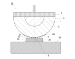
- FIG. 1 is a cross-sectional view showing an example of a printing pad 10 included in the printing apparatus 100 according to the first embodiment.
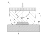
- FIG. 3 is a cross-sectional view when the printing pad 10 included in the printing apparatus 100 according to the first embodiment is pressed against a printed material 70.
- FIG. FIG. 3 is a cross-sectional view when the printing pad 10 included in the printing apparatus 100 according to the first embodiment is pressed against a printed material 70.
- FIG. FIG. 2 is a cross-sectional view showing an example of a printing original plate 50 used in the printing apparatus 100 according to the first embodiment.
- FIG. 3 is a schematic diagram of the vicinity of a printing stage 87 of the printing apparatus 100 according to the first embodiment.
- FIG. It is a modification of the blower 66 of the printing apparatus 100 according to Embodiment 1.
- 1 is an example of a functional block diagram of a printing apparatus 100 according to Embodiment 1.
- FIG. 7 is a flowchart of a method for manufacturing printed matter 70 by printing apparatus 100 according to Embodiment 1.
- FIG. 5 is an enlarged view of the contact portion between the printing surface 4 and the printing surfaces 71, 72, and 73 in FIG. 4.
- FIG. 11 is an enlarged view of the ink 40f or 40g transferred to the printing surface 73 of FIG. 10.
- FIG. 3 is a perspective view of an inner layer 1 of a printing pad 10 according to a second embodiment. 7 is a cross-sectional view showing a modification of the printing pad 10 according to the first embodiment.
- FIG. FIG. 3 is a cross-sectional view of a modification of the printing pad 10 according to the first embodiment.
- Embodiment 1 a printing pad according to the present invention will be explained with reference to the drawings.
- the present invention is not limited to the embodiments described below. Further, in each figure, the same parts are given the same reference numerals, and some explanations are omitted.
- each figure is drawn schematically, and the present invention is not limited to the illustrated shape.
- an elastic body or elasticity is not limited to one in which the load applied thereto and the amount of deformation caused by the load are in a linear relationship. This includes cases in which the applied load and the amount of deformation caused by the load have a non-linear relationship, and when the applied load is removed, the object returns to its original shape immediately or after a predetermined period of time.
- FIG. 1 is a side view showing an example of a printing apparatus 100 according to the first embodiment.
- the printing device 100 transfers the ink placed on the printing original plate 50 to the printing surface 4 of the printing pad 10, and further transfers the ink transferred to the printing surface 4 to the printing surface 71 of the printed material 70. It is.
- the printing surface 71 may have an uneven shape.
- the printing device 100 is capable of printing even on the inclined surface when the printing surface 71 has an inclined surface with respect to the pressing direction of the printing pad 10.
- the printing device 100 includes a printing pad 10 that is linearly movable in the vertical direction.
- the printing pad 10 is moved up and down by the vertical movement device 11 included in the printing device 100, presses the printing surface 4 against the printing surface 71 of the printed material 70, and transfers the ink transferred to the printing surface 4 to the printing surface 71. It is something to do.
- the printing device 100 also includes a horizontal movement device 12 .
- the horizontal movement device 12 moves the printing pad 10 and the vertical movement device 11 in the horizontal direction.
- the printing pad 10 is moved above the printed matter 70 , the cleaning device 60 , the activating device 61 , the air blowing device 62 , or the original printing plate 50 by the horizontal movement device 12 .
- the printing apparatus 100 includes, from the left side, a printing stage 87 on which a printed matter 70 is placed, a surface treatment stage 86 including a cleaning device 60, an activation device 61, and an air blowing device 62, and a printing original plate 50 placed thereon. It has a printing original plate stage 85.
- these stages can be freely arranged and can be changed as appropriate according to the convenience of the operator or the location where the printing apparatus 100 is installed. Further, each device of the printing apparatus 100 is installed in the printing apparatus 100 as necessary, and may not be installed in some cases.
- a blower 66 is installed on the printing stage 87.
- the blower 66 blows air toward the printing surface 4 of the printing pad 10.
- the printing apparatus 100 may include either the blower 66 or the air blow device 62 and may function as the blower 66 and the air blow device 62.
- FIG. 2 is a cross-sectional view showing an example of the printing pad 10 included in the printing apparatus 100 according to the first embodiment.
- FIG. 2 is a sectional view of the printing pad 10 of FIG. 1, showing a section passing through the vertex 6 of the printing pad 10 and perpendicular to the plane 13 of the support member 7 to which the base material 5 is fixed.
- the printing pad 10 has, for example, a substantially hemispherical shape.
- the shape of the printing pad 10 is not limited to this, and may be, for example, a cannonball shape, a shape with a curved surface created by rotating a parabola around its axis of symmetry, a shape such as a cut part of an ellipsoid, or a cannonball shape or a half shape.
- the shape can be changed as appropriate depending on the specifications of the printed matter 70, such as a shape in which a circular cross section is continuously extended in a straight line.
- the printing pad 10 has a top that first comes into contact with the printed matter 70 or the original printing plate 50, and the top is formed of dots or lines.
- a predetermined area of the surface of the printing pad 10 centered around the vertex 6 becomes the printing surface 4 on which ink 40 is transferred from the printing original plate 50 and transferred to the printed material 70.
- the printing surface 4 may be set so as not to include the vertex 6.
- the base material 5 of the printing pad 10 includes an inner layer 1 and an outer layer 2 disposed to cover the outer surface of the inner layer 1.
- the inner layer 1 and the outer layer 2 are each fixed to a support member 7.
- the printing pad 10 may have not only a two-layer structure but also a multi-layer structure.
- the outer layer 2 is formed by molding silicone rubber, for example.
- the outer layer 2 has elasticity (flexibility) and is mixed with silicone oil to make it easily deformable.
- the outer layer 2 has a substantially hemispherical shape, but the shape can be changed as appropriate depending on the specifications of the printed material 70 and the like.
- the outer layer 2 deforms when the printing pad 10 is pressed against the printing original plate 50, and transfers the ink 40 (see FIG. 3) placed on the placement surface 51 of the printing original plate 50 to the printing surface 4.
- the ink 40 placed on the placement surface 51 of the printing original plate 50 is arranged in correspondence with the image to be printed on the printed material 70, and forms a printing pattern.
- 3 and 4 are cross-sectional views when the printing pad 10 included in the printing device 100 according to the first embodiment is pressed against the printed material 70.
- the material of the outer layer 2 constituting the portion close to the printing surface 4 is set to have an Asker C hardness in the range of 0 to 20 points.
- the inner layer 1 inside the outer layer 2 is, for example, a plastic foam.
- the inner layer 1 is made of foamed plastic such as ABS foam or expanded polystyrene.
- the inner layer 1 has a structure having a cavity inside.
- the cavities are fine bubbles.
- the inner layer 1 is made of a member having a cavity inside and having enough strength and rigidity to maintain its shape when pressed against the printed matter 70.
- the inner layer 1 is located on the side where force is applied to press the printing surface 4 against the printing surfaces 71, 72, and 73 during printing, and is arranged inside the outer layer 2 when viewed from the printing surface 4 side. ing.
- the support member 7 is connected to the vertical movement device 11 and is a portion that transmits the force from the vertical movement device 11 to the printing pad 10.
- the hardness of the printing pad 10 is set to be low (soft).
- the hardness of the side portion that is, the hardness of the outer layer 2 must be set lower than that of the inner layer 1.
- the outer layer 2 that is directly pressed against the printing surfaces 71, 72, and 73 is formed not only on the printing surface 71 but also on the printing surface 72, which is a curved surface, and on an inclined surface with respect to the direction in which the printing pad 10 moves. It has the advantage of being easily deformed to follow the printing surface 73.
- the hardness of each part of the base material 5 is not limited to the above hardness.
- the printing pad 10 is preferably configured such that the printing surface 4 has an area that is at least 1.5 times the area of the printing surfaces 71, 72, and 73. This reduces the rate of deformation (ratio of the amount of deformation to the size of the printing pad 10) when the printing pad 10 is pressed against the printed matter 70, so that slipping of the printing surface 4 against the surface to be printed can be suppressed. Furthermore, by reducing the hardness of the printing pad 10, it is possible to suppress the slippage of the printing surface 4 against the printing surface.
- the printing surface 4 is on the surface of the outer layer 2.
- the surface of the inner layer 1 facing the surface (printed surface 4) may have a similar shape to the surface of the outer layer 2.
- the volume of the internal layer 1 including the internal cavities (in the first embodiment, internal air bubbles) is preferably set to 40% or less of the total volume of the base material 5 .
- a surface treatment stage 86 is arranged next to the printing stage 87 of the printing apparatus 100.
- a cleaning device 60 is installed on the surface treatment stage 86.
- the cleaning device 60 includes, for example, paper or adhesive tape.
- the printing surface 4 of the printing pad 10 is pressed against the surface of paper or adhesive tape to remove ink 40, dirt, dust, etc. remaining after printing.
- the activation device 61 includes a storage tank that stores liquid and an absorption unit that absorbs and holds the liquid.
- the printing surface 4 of the printing pad 10 is pressed against the surface of the absorption unit, so that the liquid held by the absorption unit adheres thereto.
- the printing pad 10 makes it easier to transfer the ink 40 placed on the printing original plate 50 to the printing surface 4 by adhering or impregnating water or a solvent onto the base material 5 .
- the liquid is appropriately selected depending on its properties with the ink 40, and has the property of softening the hard ink 40.
- the ink 40 is made by adding a pigment or dye to water or a solvent.
- the liquid used in the activation device 61 is, for example, a mixture of synthetic resins such as acrylic resin or urethane resin, and water, thinner, xylene, or toluene, and has an affinity with the solvent contained in the ink 40. It is better to choose the higher one.
- the liquid used in the activation device 61 is not limited to the above.
- the absorption unit of the activation device 61 may be configured by laminating thin sheet-like absorbent materials, for example.
- the absorbent material is made of paper, for example, but is not limited to paper, and may be made of other materials such as cloth or resin as long as it absorbs liquid.
- the absorption unit may be formed by laminating paper on a sponge-like resin.
- the surface of the absorption unit against which the printing surface 4 of the printing pad 10 is pressed may be contaminated by dirt such as ink 40 remaining on the printing surface 4 of the printing pad 10, or the surface of the absorption unit may be scraped.
- the paper that makes up the product may tear.
- the paper located at the top layer of the absorbent unit can be removed by peeling from the top layer of the absorbent unit, and the stack can be removed one by one, or the upper layer can be replaced mechanically. It is composed of However, the method for replacing the paper located at the top layer is not limited to this method.
- the absorption unit has a structure in which the uppermost layer, such as paper, is removable or replaceable, and the surface is always kept clean and permeated with liquid. Therefore, by pressing the printing surface 4 of the printing pad 10 against the surface of the absorption unit, the printing surface can be activated.
- the absorption unit of the activation device 61 is not limited to a laminated structure, and may be formed of a single member.
- Air blow device 62 adjusts the amount of water or solvent attached to the printing surface 4 of the printing pad 10 by the activation device 61 to an appropriate amount.
- the air blowing device 62 blows air toward the printing surface 4 after being pressed against the activation device 61 and before the ink is transferred to remove excess water or solvent from the printing surface 4.
- the type and quantity of the air blow device 62, and the direction in which air is blown are not limited.
- the activation device 61 can control the amount of liquid adhering to the printing surface 4 to an appropriate amount, the air blow device 62 may be omitted.
- ⁇ Printing original plate 50> The printing original plate 50 is placed on the printing original plate stage 85, and the ink 40 is placed on the placement surface 51, and by pressing the printing surface 4 of the printing pad 10 against the placement surface 51, Ink 40 is transferred onto the printing surface 4.
- FIG. 5 is a cross-sectional view showing an example of a printing original plate 50 used in the printing apparatus 100 according to the first embodiment.
- the original printing plate 50 shown in FIG. 5 is an intaglio plate.
- the original printing plate 50 has a flat plate shape and includes a support 53 and a surface layer 52 formed on the support 53.
- the surface layer 52 is made of a material that is inkphobic at least on the mounting surface 51 side against which the printing surface 4 of the printing pad 10 is pressed.
- the surface layer 52 is partially destroyed and removed by, for example, a laser beam, so that a portion made of an ink-phobic material is removed. That is, the surface layer 52 is removed by, for example, a laser beam, and a recess 54 opening in the mounting surface 51 is formed.
- the surface layer 52 is an ink-phobic layer having ink-phobic properties to which the ink 40 is difficult to adhere. Further, the support 53 is an ink-friendly layer having ink-friendly properties to which the ink 40 easily adheres.
- the surface layer 52 is made of silicone rubber or silicone resin, for example. Silicone rubber and silicone resin have ink-phobic properties and are chemically stable, so they are preferably used as the surface layer 52 of the printing original plate 50.
- the surface layer 52 is not limited to silicone rubber and silicone resin, and may be made of other materials as long as they are ink-phobic.
- the surface layer 52 and the support body 53 are each formed of one layer in FIG. 5, they are not limited to this form.
- the surface layer 52 may be formed of a single layer of a material that is ink-phobic and can be destroyed by laser light, or may be formed of an ink-phobic layer on the side to which the printing pad 10 is pressed and an ink-phobic layer on the support 53 side. It may also include a recording layer.
- the recording layer absorbs laser light and converts it into heat, for example, and reduces the adhesive strength between the recording layer and the ink-phobic layer, thereby making it possible to remove the ink-phobic layer from the printing original plate 50.
- the recording layer absorbs laser light and converts it into heat, for example, and the recording layer is destroyed by the heat, thereby reducing the bonding force between the support 53 and the surface layer 52 and providing ink repellency.
- the surface layer 52 is removed from the original printing plate 50.
- the surface layer 52 is composed of an ink-phobic layer and a recording layer
- the ink-phobic layer is made of silicone rubber or silicone resin
- the recording layer is made of a heat-sensitive or photosensitive material.
- printing is performed by intaglio printing, but it can also be performed by letterpress printing.
- the support 53 may be formed of, for example, a single layer of a metal plate made of aluminum for holding the shape of the printing original plate 50, or a parent layer formed of a material having ink affinity on the surface of the metal plate. It may also include an ink layer. Further, the support body 53 may be subjected to a surface treatment to roughen the surface by etching the surface of the metal plate or the like. Furthermore, a primer layer may be formed on the surface of the support 53 to improve the bonding force with the surface layer 52.
- a recessed portion 54 is formed by removing the surface layer 52.
- the ink 40 is supplied to the placement surface 51 by the ink placement device 63, and the ink 40 is placed inside the recess 54.
- the portion where the surface layer 52 remains forms an ink-poor region 57, to which the ink 40 is not attached.
- the recess 54 forms an ink-friendly region 58, on which the ink 40 is placed. That is, the placement surface 51 has an ink-poor area 57 and an ink-friendly area 58 , and the ink 40 is placed only on the ink-friendly area 58 by the ink placement device 63 .
- the thickness h1 of the surface layer 52 is, for example, 3 ⁇ m or less.
- the width w2 which is the width of the bottom 55 of the recess 54 in the direction along the placement surface 51, is the width of the opening 56 of the recess 54.
- w1 becomes large.
- the thickness h1 of the surface layer 52 is set to 3 ⁇ m or less, the difference between the width w2 of the bottom 55 of the recess 54 and the width w1 of the opening 56 becomes small. This reduces the internal volume of the recess 54.
- the thickness h1 of the surface layer 52 is formed to be 3 ⁇ m or less, it becomes easy to supply energy to the layer sensitive to laser light when forming the recess 54 with laser light.
- the laser beam can form the shape of the bottom portion 55 of the recessed portion 54 of the printing original plate 50 with high accuracy, and it becomes possible to further reduce the width w2.
- the width w2 of the bottom 55 of the recess 54 is formed to be 20 ⁇ m or less, preferably 10 ⁇ m or less, and more preferably 5 ⁇ m or less.
- the ink placement device 63 includes an ink holding section 64 that is a roller whose surface is provided with a material that holds ink.
- the ink holding section 64 is configured to rotate around a rotation axis 65.
- the ink placement device 63 places the ink 40 on the placement surface 51 by bringing the ink holding section 64 into contact with the placement surface 51 of the printing original plate 50 and rotatingly moving the ink holding section 64 on the placement surface 51. It is placed on the ink-friendly area 58.
- the ink placement device 63 is not limited to the configuration including the rollers shown in FIG.
- the holding part 64 may move perpendicularly to the mounting surface 51.
- the printing original plate 50 includes an ink-sparse area 57 and an ink-friendly area 58, and since the ink-sparse area 57 repels ink, the ink placement device 63 does not apply ink to the ink-friendly area 58 even if the ink-friendly area 58 is small. It can be loaded. Furthermore, the ink placement device 63 does not need to include a doctor blade for removing excess ink after ink is placed, since the ink sparse region 57 repels excess ink.
- the printing device 100 may include a plurality of ink placement devices 63.
- one printed matter 70 may be printed by a plurality of printing devices 100.
- each of the plurality of printing devices 100 corresponds to each of the plurality of monochrome printing original plates 50.
- FIG. 6 is a schematic diagram of the print stage 87 and its surroundings of the printing apparatus 100 according to the first embodiment.
- the printing device 100 includes a blower 66 that blows air to the printing surface 4 of the printing pad 10 in a state where the ink 40 is transferred to the printing surface 4 .
- the blower 66 is arranged around the printing stage 87 where the printed matter 70 is placed. The blower 66 blows air onto the printing surface 4 to which the ink 40 is attached and before it is pressed against the printing surfaces 71, 72, and 73.
- the blower 66 blows air toward the printing surface 4 to evaporate the liquid attached to the printing surface 4 by the activation device 61 and the liquid such as the solvent that has soaked into the ink 40. This reduces the affinity between the ink 40 and the printing surface 4. Additionally, the viscosity of the ink 40 increases. That is, the ink 40 is cured by the air blowing by the blower 66.
- the blower 66 is arranged with the blower port 66a facing the printing surface 4 of the printing pad 10 before contacting the printed matter 70.
- the blowers 66 are preferably installed at multiple locations so that air hits the printing surface 4.
- the blower 66 may include a heater 67 inside to adjust the temperature of the air sent to the printing surface 4.
- the temperature of the air sent to the printing surface 4 may be adjusted by detecting the temperature of the air sent to the printing surface 4 with a temperature sensor 68 (see FIG. 8) and adjusting the output of the heater 67.
- the temperature sensor 68 may detect the room temperature of the environment in which the printing apparatus 100 is placed, and the output of the heater 67 may be adjusted according to the room temperature.
- the blower 66 has an air outlet 66a at one end of a cylindrical casing, and an inlet 66b for taking in air from which a fan and a heater 67 are installed inside the other end of the casing.
- FIG. 7 shows a modification of the blower 66 of the printing apparatus 100 according to the first embodiment.
- the blower 66 is not limited to a dryer type as shown in FIG. 6, but may have a form in which a large number of holes are provided in a flat plate to form a blower port 66a, for example.
- the blower 66 shown in FIG. 7 may be provided on the printing stage 87 or elsewhere. For example, it may be provided on the surface treatment stage 87 like the blower 66A shown in FIG.
- the printing surface 4 is moved in front of the air outlet 66a of the air blower 66, and the printing surface 4 is controlled so that the air from the air blower 66 hits the printing surface 4. Ru.
- the range S in which the blower port 66a is provided is set larger than the width of the printing surface 4.
- the blower 66 shown in FIG. 7 is configured to be supplied with air from an inlet 66b and blow out air heated by a heater 67 disposed inside from an air blower 66a.
- FIG. 8 is an example of a functional block diagram of the printing apparatus 100 according to the first embodiment. Next, a method for manufacturing printed matter using the printing apparatus 100 will be described.
- the printing apparatus 100 includes a control device 20.
- the control device 20 is composed of, for example, a microcomputer, and includes an arithmetic device 20a and a storage device 20b.
- the functions of the control device 20, that is, each functional block shown in FIG. 8, are realized using the arithmetic device 20a and the storage device 20b (see FIG. 1).
- the storage device 20b is a ROM that holds programs, data, etc. in advance, a RAM that temporarily stores data during program execution, or the like.
- nonvolatile or volatile storage devices such as flash memory, EPROM (Erasable and Programmable ROM), and EEPROM (Electrically Erasable and Programmable ROM) can be used.
- a typical semiconductor memory is used.
- a removable recording medium such as a magnetic disk, a flexible disk, an optical disk, a CD (Compact Disc), an MD (Mini Disc), and a DVD (Digital Versatile Disc) may be used.
- the storage device 20b can store information obtained from the temperature sensor 68 and the like, and information processed by the arithmetic device 20a.
- the arithmetic device 20a performs various processes to execute the functions of the control device 20.
- the arithmetic device 20a compares, for example, room temperature information from the temperature sensor 68 with a temperature threshold stored in advance in the storage device 20b, and determines whether the room temperature is higher than the threshold.
- the control device 20 performs control to suppress the output of the heater 67 to a predetermined value.
- the control device 20 may perform control to shorten the operating time of the blower 66 when the room temperature is higher than a threshold value.
- the control device 20 may perform control such as limiting the time during which the printing pad 10 stops in front of the blower 66 and is exposed to air.
- FIG. 9 is a flowchart of a method for manufacturing printed matter 70 by printing apparatus 100 according to the first embodiment.
- the printing apparatus 100 includes a starting process that is performed when the printing apparatus 100 is started or restarted, and a repeating process that produces a plurality of printed matter 70.
- the starting process is performed depending on the state of the printing pad 10, and may be omitted.
- the start process is, for example, a process performed immediately after starting the printing apparatus 100. Since the surface of the printing pad 10 may not be activated immediately after the production of the printed matter 70 is started, a process of appropriately activating the printing surface 4 of the printing pad 10 is performed. Since the printing pad 10 is made of a material such as silicone rubber to which hard ink 40 does not easily adhere, even if it is pressed directly onto the printing original plate 50, the ink 40 may not be transferred as intended. Therefore, the printing apparatus 100 according to the first embodiment activates the printing surface 4 as necessary in the starting process.
- the printing device 100 moves the printing pad 10 above the activation device 61 and lowers it toward the activation device 61.
- the printing pad 10 is raised after the printing surface 4 is pressed against the absorption unit of the activation device 61 and a predetermined area including the printing surface 4 comes into contact with the absorption unit. This is called an activation step (SP1).
- an activation step SP1
- liquid such as water or a solvent that has soaked into the absorption unit of the activation device 61 adheres to or soaks into the printing surface 4 of the printing pad 10 .
- the printing surface 4 has minute irregularities formed on its surface, and can hold the liquid from the absorption unit when it adheres thereto.
- the unevenness on the printing surface 4 is preferably formed to have a height difference of 2 to 5 ⁇ m.
- the pad control unit 21 of the control device 20 controls the vertical movement device 11 and the horizontal movement device 12. As a result, the position of the printing pad 10, the movement from the position at the start of manufacturing to the activation device 61, and the pressing operation are controlled.
- the activation unit 24 controls or provides notification to maintain the amount of liquid contained in the absorption unit of the activation device 61 at a predetermined amount. Furthermore, when the absorption unit has deteriorated, the activation unit 24 controls or notifies the absorption unit to be updated.
- the printing apparatus 100 After the activation step (SP1) is completed, it is determined whether the amount of liquid adhering to the printing surface 4 of the printing pad 10 is an appropriate amount (SP2). If the amount of liquid adhering to the printing surface 4 is not appropriate (NO in SP2), the printing apparatus 100 performs an air blowing process (SP3). In the air blowing process, the air blowing device 62 blows air onto the printing surface 4 of the printing pad 10 to remove excess liquid adhering to the printing surface 4. Note that the case where the amount of liquid adhering to the printing surface 4 is not appropriate is the case where an excessive amount of liquid is adhering to the printing surface 4.
- the air blow section 23 of the control device 20 controls the operation of the air blow device 62.
- the air blow unit 23 drives the air blow device 62 to perform an air blow process when the printing pad 10 moves to a place where the air sent from the air blow device 62 hits.
- the printing device 100 After completing the air blowing step (SP3), it is determined whether the amount of liquid adhering to the printing surface 4 of the printing pad 10 is an appropriate amount (SP4). If excess water or solvent still adheres to the printing surface 4 of the printing pad 10 (NO in SP4), the printing device 100 performs the absorption process (SP5). In the absorption process, the printing device 100 presses the printing surface 4 of the printing pad 10 against the cleaning device 60. As a result, excess liquid adhering to the printing surface 4 of the printing pad 10 is removed.
- the repeated steps include an ink placement step (S1), an ink transfer step (S2), an air blowing step (S3), a printing step (S4), a cleaning step (S5), an activation step (S6), and an air blowing step (S8). , and an absorption step (S10).
- S1 ink placement step
- S2 ink transfer step
- S3 air blowing step
- S4 printing step
- S5 cleaning step
- S6 an activation step
- S8 air blowing step
- absorption step S10
- the printing apparatus 100 includes an ink placement process (S1), an ink transfer process (S2), an air blowing process (S3), a printing process (S4), a cleaning process (S5), and an activation process ( Step S6), air blowing step (S8), and absorption step (S10) are performed in this order.
- the repeating steps are not limited to this order.
- the printing apparatus 100 performs the blowing step (S3) to the absorption step (S10).
- the printing apparatus 100 may perform the next ink placement step (S1) in parallel while performing the blowing step (S3) to the absorption step (S10).
- a printed image is formed on the surface of the printed material 70 every time the printing process (S4) is performed.
- the number of printed matter 70 is not limited to one, and a plurality of printed matter 70 may be printed at the same time.
- a plurality of printing pads 10 may be installed in the printing apparatus 100.
- the ink placement step (S1) is a step in which the ink 40 is placed on the printing original plate 50 by the ink placement device 63.
- the ink placement device 63 brings the ink holding section 64 into contact with the placement surface 51 of the printing original plate 50 and rolls the ink holding section 64 onto the placement surface 51 .
- the ink 40 absorbed by the ink holding portion 64 is placed only on the ink-friendly area 58 provided on the placement surface 51.
- the ink holding portion 64 that has absorbed the ink 40 also contacts the ink sparse region 57 . However, the ink 40 is not placed on the sparse ink region 57 because the ink 40 is repelled.
- the ink 40 is desirably set to be hard so that it is repelled by the sparse ink region 57.
- the viscosity of the ink 40 is preferably set in the range of 700 to 1200 P (Poise).
- the ink placement unit 25 of the control device 20 controls the operation of the ink placement device 63 and places the ink 40 on the printing original plate 50 before the printing pad 10 is pressed against the printing original plate 50.
- the printing surface 4 of the printing pad 10 is pressed against the mounting surface 51 of the printing original plate 50.
- the printing surface 4 of the printing pad 10 contacts the ink 40 placed on the ink-friendly area 58 of the printing original plate 50.
- the printing pad 10 moves upward, and the printing surface 4 separates from the mounting surface 51 of the printing original plate 50.
- the ink 40 that has come into contact with the printing surface 4 moves to the printing surface 4 as it is.
- the ink 40 is placed on the printing surface 4 according to the ink-friendly area 58 placed on the placement surface 51 of the printing original plate 50.
- the pressing of the printing pad 10 against the printing original plate 50 is also controlled by the pad control section 21 .
- the printing surface 4 of the printing pad 10 has water or solvent attached or permeated through the activation process (SP1 or S6), making it easier for the ink 40 to adhere thereto.
- SP1 or S6 the activation process
- the viscosity of the ink 40 be within the range of 700P to 1200P.
- the printing surface 4 of the printing pad 10 is activated by the activation device 61, so that the ink 40 easily adheres even if the ink 40 has a high viscosity.
- blowing process In the blowing step (S3), the printing pad 10 is moved to a position where the air sent from the blower 66 hits the printing surface 4.
- the blower 66 starts operating and blows air onto the printing surface 4.
- the blower unit 22 of the control device 20 may control the operation of the blower 66 to be stopped, or may control the movement of the printing pad 10 that has been stopped. Control may be performed to start the process.
- the air blown out from the blower 66 is controlled at, for example, 40 to 80°C.
- the time for blowing air onto the printing pad 10 may be controlled by the temperature of the indoor environment.
- the blower unit 22 receives room temperature information from the temperature sensor 28 and controls the blower 66 to blow air for a length of time set according to the room temperature. For example, if the room temperature is high, the spraying time may be shortened.
- the blower section 22 may adjust the length of time for blowing air according to information from the temperature control section 26 that controls the output of the heater 67 built into the blower 66. Specifically, the blower unit 22 controls the amount of air blown based on information about the temperature of the air blown out from the blower 66 whose temperature is measured by the temperature sensor 68 .
- the viscosity of the ink 40 on the printing surface 4 is preferably adjusted to a range of, for example, 900 P or more and 1100 P or less. However, the viscosity of the ink is not limited to that described above.
- the printing surface 4 of the printing pad 10 to which the ink 40 is attached is pressed against the printed material 70.
- the printing apparatus 100 can print not only on a flat surface but also on printing surfaces 71, 72, and 73 of a printed matter 70 as shown in FIGS. 3 and 4.
- the printed surface 71 of the printed material 70 is a flat surface.
- the printing surface 72 is formed of a curved surface
- the printing surface 73 is a flat surface but sloped with respect to the direction in which the printing pad 10 moves.
- the printing pad 10 is pressed toward the printing stage 87 so that the printing surface 4 to which the ink 40 is attached is brought into close contact with the printing surfaces 71, 72, and 73.
- the ink 40 adhering to the printing surface 4 comes into contact with the printing surfaces 71, 72, and 73 and is transferred. Movement of the printing pad 10 in the printing process is also controlled by the pad control section 21.
- the printed matter 70 is positioned and fixed on the printing stage 87. This determines the positional relationship between the printing pad 10 and the printing surfaces 71, 72, and 73, allowing printing to be performed on the printing surfaces 71, 72, and 73 with high precision.
- the cleaning step (S5) the printing surface 4 of the printing pad 10 after the ink 40 has been transferred to the printing surfaces 71, 72, and 73 is pressed against the flat cleaning surface of the cleaning device 60.
- the ink 40 remaining on the printing pad 10 is made to adhere to the cleaning surface.
- the cleaning surface may be comprised of, but not limited to, paper or adhesive tape.
- the activation step (S6) is a step having the same contents as the activation step (SP1) in the starting step.
- the air blowing step (S8) is a step having the same contents as the air blowing step (SP3) in the starting step.
- the absorption step (S10) is also a step having the same contents as the absorption step (SP5) in the starting step.
- the air blowing step (S6) and the absorption step (S10) are performed depending on the amount of liquid such as water or solvent adhering to the printing surface 4 of the printing pad 10, and one of them may be omitted, At least one of them may be performed multiple times.
- the air blowing step (S8) and the absorption step (S10) are performed according to the activation state of the printing surface 4 after checking the state of the printing surface 4 of the printing pad 10 (S7 and S9) before each step. This will be implemented in accordance with the following.
- the printing original plate 50 is composed of, for example, a plurality of monochrome printing original plates 50
- printing may be performed using a plurality of printing devices 100 corresponding to each of the plurality of monochrome printing original plates 50.
- one printing device 100 includes a monochrome printing original plate 50, and prints a printed matter 70 using only magenta ink. Thereafter, the printed matter 70 is printed using only cyan ink in another printing apparatus 100 equipped with the monochrome printing original plate 50. Printing can be performed by repeating this process as many times as the number of monochromatic printing plates 50.
- the printing apparatus 100 When the printing apparatus 100 includes a plurality of printing original plate stages 85 and a plurality of ink placement devices 63 corresponding to a plurality of monochrome printing original plates 50, the printing apparatus 100 has at least one ink placement device for one printed matter 70. The process, ink transfer process, and printing process are repeated the same number of times as the number of monochrome printing original plates 50. Further, the printing apparatus 100 may repeat at least one of the cleaning process, the activation process, the air blowing process, and the absorption process the same number of times as the number of the plurality of monochrome printing original plates 50.
- the manufacturing method is not limited to the above, and each step can be changed and implemented as appropriate.
- the printing pad 10 has a printing surface 4 which is located on the front surface and is pressed against a printing original plate on which ink is placed and printing surfaces 71, 72 and 73 to be printed, and a printing surface 4 which is arranged inside. and an outer layer 2 provided in contact with the surface of the inner layer 1 on the side where the printing surface 4 is arranged, and the outer layer 2 is provided on the printing surfaces 71, 72, and 73.
- the printing surface 4 is configured to follow and adhere to the printing surfaces 71, 72, and 73 when pressed, and the inner layer 1 has a cavity formed inside. With this configuration, the printing pad 10 can be lightweight because the inner layer 1 has a cavity.
- the printing pad 10 is configured such that the outer layer 2 is deformed to follow the shape of the printed surfaces 71, 72, and 73 of the printed material 70, so that it can print on the uneven printed material 70, and is lightweight. It becomes possible to print on the printed matter 70 having a complicated printing surface while achieving the desired printing speed. Further, in the printing pad 10, the elastic material constituting the outer layer 2 can be reduced by the amount of the inner layer 1.
- the inner layer 1 and the outer layer 2 are each fixed to the support member 7 at the end opposite to the end on the side where the printing surface 4 is arranged.
- the printing device 100 applies a load to the outer layer 2 via the support member 7 and the inner layer 1 to deform it, so that the printing surface 4 can be applied even to inclined surfaces such as the printing surfaces 72 and 73.
- the outer layer 2 can be deformed accordingly.
- the outer layer 2 will swell in the horizontal direction.
- the printed surface 4 does not come into close contact with the printed surface 73.
- the outer layer 2 can be deformed in a direction that reduces the space that the inner layer 1 should originally have, it is difficult to push the peripheral portion of the printing surface 4 away from the apex 6 toward the upper surface of the printing stage 87.
- the inner layer 1 is made of a material that is difficult to deform, the outer layer 2 is prevented from deforming inward.
- the outer layer 2 is fixed to the surface of the inner layer 1, it is possible to prevent the outer layer 2 from deforming outwardly. This makes it easy for the printing surface 4 to follow the printing surfaces 72 and 73 as well.
- the inner layer 1 of the printing pad 10 is made of, for example, plastic foam. As a result, even when the printing pad 10 is pressed against the printed material 70, the inner layer 1 is prevented from deforming, and the load from the printing device 100 is easily transmitted to the outer layer 2. Moreover, since the inner layer 1 has higher rigidity than the outer layer 2, it is possible to reduce the weight of the printing pad 10 while efficiently deforming only the outer layer 2.
- the outer layer 2 is made of, for example, soft silicone rubber, so it is heavy and the material cost is relatively high. However, since the silicone rubber can be reduced by the volume of the inner layer 1, the weight of the printing pad 10 as a whole is reduced. This has the advantage of reducing costs.
- the volume of the inner layer 1 including the cavity is preferably 30% or less of the combined volume of the outer layer 2 and the inner layer 1 including the cavity.
- the outer layer 2 can follow the printed matter 70 even if it has a complicated uneven shape. For example, by determining the height dimension of the printing pad 10 according to the dimension H of the convex portion of the printed matter 70, if the volume of the internal layer 1 is 30%, approximately half the thickness of the printing pad 10 can be reduced. Since it is the outer layer 2, the printing surface 4 can follow the printing surfaces 72 and 73. In addition, since the surfaces of the inner layer 1 and the outer layer 2 on which the printed surface 4 is arranged have similar shapes, the outer layer 2 has a uniform thickness along the printed surface 4 and is uneven in deformation. It is easy to follow the printing surfaces 72 and 73.
- the shape of the inner layer 1 is not limited to a shape similar to the surface shape of the outer layer 2.
- the printing device 100 also includes a printing pad 10 having a printing surface 4, a sparse ink region 57 that does not receive ink 40 on a placement surface 51 on which ink 40 is placed, and an ink sparse region 57 that does not receive ink 40; a printing original plate stage 85 on which a printing original plate 50 having an ink-friendly area 58 is placed; a printing stage 87 on which a printed matter 70 is placed; and a blower 66 that blows air toward the printing surface 4 of the printing pad 10. , is provided.
- the printing pad 10 is configured to be movable between the printing original stage 85 and the printing stage 87, and is configured to move up and down with respect to the printing original stage 85 or the printing stage 87. Then, the blower 66 sends air toward the printing surface 4 of the printing pad 10 on which the ink 40 on the placement surface 51 of the printing original plate 50 has been transferred to the printing surface 4 .
- the printing apparatus 100 can evaporate the liquid adhering to or soaking into the printing surface 4 of the printing pad 10 immediately before transferring the ink 40 to the printed material 70. .
- the affinity of the printing surface 4 with the ink 40 which has been in a state in which a liquid such as water or a solvent has been attached in the activation process and is relatively easily attached to the ink 40, is suppressed immediately before being pressed against the printed material 70. Therefore, even if slippage occurs between the printing surfaces 71, 72, and 73 and the printing surface 4, the ink 40 is in a state where it is difficult to adhere to the printing surface 4, and the printing surface 71, After being attached to 72 and 73, deformation or movement can be suppressed.
- slipping means that the printing surface 4 is displaced in the direction along the printing surfaces 71, 72, and 73 while the printing surface 4 is pressed against the printing surfaces 71, 72, and 73.
- FIG. 10 is an enlarged view of the contact portion between the printing surface 4 and the printing surfaces 71, 72, and 73 in FIG. 4.
- FIG. 11 is an enlarged view of the ink 40f or 40g transferred to the printing surface 73 of FIG. 10.
- the various parts of the printing pad 10 and the deformations of the inks 40a to 40g are schematically shown, and the structure and material of the printing pad 10 and the configuration of the printing apparatus 100 are limited. It's not a thing.
- the left side diagram shows the ink 40 in a state where the printing pad 10 is pressed against the printed matter 70.
- the diagram on the right shows a state in which ink 40f or 40g is transferred to the surface of printed matter 70.
- the printing apparatus 100 may transfer the ink 40 to a curved surface or a surface inclined with respect to the moving direction of the printing pad 10, like the printing surfaces 72 and 73.
- inks 40a to 40g transferred from the original printing plate 50 are placed.
- the inks 40a to 40d are transferred onto a printing surface 71 perpendicular to the direction of movement of the printing pad 10.
- the ink 40e is transferred to the printing surface 71, which is a curved surface.
- the inks 40f and 40g are transferred onto the printing surface 73, which is a surface inclined with respect to a surface perpendicular to the moving direction of the printing pad 10.
- the printed surfaces 71, 72, and 73 of the printed material 70 are merely examples, and the printed material 70 may have other uneven shapes.
- the printing pad 10 deforms so that the printing surface 4 also follows the printing surfaces 72 and 73 having an uneven shape. At this time, the printing surface 4 is slightly displaced in the direction along the printing surfaces 72 and 73. Therefore, as shown in FIG. 11, the inks 40f and 40g that have come into contact with both the printing surface 4 and the printing surface 73 slide in the direction along the printing surface 73 according to the strain ⁇ 1 of the printing surface 4. transcribed. The ink 40 and the printing surface 73 come into contact with each other while the printing surface 4 and the printing surface 73 are separated by a distance L1. The printing surface 4 continues to deform while the printing pad 10 is pressed against the printed material 70 and crushed.
- the inks 40f and 40g are deformed between the printing surface 4 and the printing surface 73 during the period from when they come into contact with the printing surface 73 until the printing pad 10 is completely deformed.
- the existing inks 40f and 40g have a width d2 and are transferred to the printing surface 73.
- the deformation of the inks 40f and 40g shown in FIG. 11 may occur in any of the inks 40a to 40f if the amount of deformation of the printing pad 10 is large.
- the inks 40a to 40f may be collectively referred to as ink 40.
- Embodiment 1 by blowing air onto the surface of the printing surface 4, the ink 40 is cured, and the affinity between the printing surface 4 and the ink 40 is reduced. Therefore, in the left view of FIG. 11, even if the printing surface 4 is deformed so as to slide in the direction along the printing surface 73, the ink 40 is hardened, so crushing and sliding are suppressed, and the printing surface 4 is Less susceptible to deformation. Therefore, d2 shown in the right-hand diagram of FIG. 11 is kept small. That is, according to printing by the printing apparatus 100 according to the first embodiment, even if there is a strain ⁇ 1 of the printing pad 10, the difference between d1 and d2 in FIG. 11 can be suppressed to a small value. Further, in FIG.
- the shape of the ink 40 is deformed into a triangle in the right-hand diagram, but according to printing by the printing apparatus 100 according to the first embodiment, the ink 40 is transferred to the printing surface 73. Since the ink 40 is cured beforehand, deformation of the ink 40 can also be suppressed.
- the printed matter 70 includes printing surfaces 72 and 73 that are inclined with respect to the direction in which the printing pad 10 is pressed, and the printing surface 4 is also pressed against the printing surfaces 72 and 73 to ink. 40 transfers are made.
- the printing pad 10 deforms along the printing surfaces 72 and 73 and is pressed to the extent that it comes into close contact with the printing surfaces 72 and 73 and the upper surface of the printing stage 87.
- the printing pad 10 is made of a material that is easily deformed, such as silicone rubber.
- the amount of deformation of the printing pad 10 is larger when pressed against the printed material 70 than when pressed against the original printing plate 50, and the printing pad 10 is stretched or Some parts may be compressed. Then, slippage occurs between the printing surface 71, 72, or 73 and the printing surface 4.
- the printing surface 4 is attached to or soaked with liquid, and has a high affinity with the ink 40. Therefore, the printing surface 4 is in a state where the ink 40 from the printing original plate 50 is easily attached.
- the ink 40 When the printing surface 4 is pressed against the printed matter 70 while the ink 40 is easily attached to the printing surface 4 as described above, the ink 40 will adhere to the printing surface 71, 72, or 73, and will not stick to the printing surface 4. Also, the ink 40 is relatively easy to adhere to. Therefore, when the ink 40 comes into contact with both the printing surface 4 and the printed material 70, the printing surface 4 deforms or moves the ink 40 attached to the printed material 70. In particular, on the printing surfaces 72 and 73 where slipping between the printing surface 4 and the surface of the printed material 70 is relatively easy to occur, the transferred ink 40 is deformed in the direction along the surface of the printed material 70 as explained with reference to FIG. There are cases.
- the printing surface 4 may be moved from the position where the ink 40 initially contacted the surface of the printed material 70. Then, the ink 40 may not be arranged in the expected position and shape on the surface of the printed matter 70, and the accuracy of the printed image may deteriorate.
- the ink 40 is hardened and crushed. It becomes difficult to slip, and the affinity between the printing surface 4 and the ink 40 can be reduced. Therefore, when the printing surface 4 is pressed against the printed material 70, the ink 40 easily separates from the printing surface 4, and even if slippage occurs between the printing surface 4 and the printed surfaces 71, 72, and 73, the ink 40 will be removed from the printing surface 4. Deformation or movement caused by sliding movement is suppressed.
- the ink 40 hardens and is hard to crush and slip, when it comes into contact with the printing surface 71, 72, or 73, it remains in the attached position even if the printing surface 4 slips.
- the ink 40 is hard and has low affinity with the printing surface 4, so if the ink 40 adheres to the printing surface 71, 72, or 73, even if the printing surface 4 slides and moves, the ink 40 Since it slides on the surface of the printing surface 4, it is prevented from moving from the position where it is attached.
- the ink 40 becomes relatively hard while remaining attached to the printing surface 4.
- the ink 40 is relatively hard when it is transferred from the printing surface 4 to the printing surfaces 71, 72, and 73, deformation of the ink 40 due to slipping of the printing surface 4 can be suppressed.
- the amount of ink 40 is reduced when the printing surface 4 is displaced along the printing surfaces 71, 72, and 73 after the ink 40 contacts the printing surfaces 71, 72, and 73. Deformation and movement can be suppressed. Note that, as described with reference to FIG. 11, the smaller the ink 40, the more the deformation and movement can be suppressed. Therefore, the printing apparatus 100 can print with higher precision by using the above-described printing pad 10, printing original plate 50, and air blowing by the blower 66 in combination.
- FIG. 12 is a modified example of the flowchart from the time when the printing pad 10 receives the ink 40 from the printing plate 50 to when it is pressed against the printed material 70 in the flowchart of the method for manufacturing the printed material 70 by the printing apparatus 100 according to the first embodiment. be.
- the printing pad 10 After being pressed against the original printing plate 50, the printing pad 10 is moved to the printing stage 87 on which the printed material 70 is placed and is pressed against the printed material 70. During this time, air from the blowers 66 and 66A is blown onto the printing surface 4 of the printing pad 10, and then the printing surface 4 is pressed against the printed material 70.
- FIG. 10 shows the details of the control flow regarding the movement of the printing pad 10 at that time.
- ink transfer process In the ink transfer step (S2), the printing surface 4 of the printing pad 10 is pressed against the mounting surface 51 of the printing original plate 50. Next, the printing pad 10 is removed upward from the original printing plate 50 (S2-2). Then, the printing pad 10 is moved from the printing original stage 85 to above the printing stage 87 (S2-3).
- the above steps are basically the same as in the first embodiment.
- the printing pad 10 that has moved above the printing stage 87 moves at the first speed toward the printed matter 70 placed on the printing stage 87.
- the first speed is set in consideration of minimizing the time required for the printing process (S2-4).
- the pad control unit 21 controls the speed of the printing pad 10 according to the specifications of the printing pad 10 such as size and hardness.
- the printing pad 10 moving at the first speed is stopped at a predetermined position away from the printed material 70 (S2-5).
- the printing pad 10 is stopped for the next blowing step (S3), so that the air from the blower 66 hits the printing surface 4, and the printing pad 10 made of a soft material is
- This is a process to suppress vibration caused by moving at high speed.
- the pad control unit 21 controls the time during which the printing pad 10 is stopped based on information such as the size, hardness, first speed setting, and printing of the printing pad 10 .
- the blower 66 blows air onto the printing surface 4 of the printing pad 10 (S3). This step is the same as in the first embodiment.
- the printing pad 10 is moved at the second speed (S3-2).
- the pad control unit 21 moves the printing pad 10 toward the printing stage 87 on which the printed matter 70 is placed.
- the second speed is set lower than the first speed.
- the pad control unit 21 may control the printing pad 10 to gradually increase the speed until it reaches the second speed.
- the pad control unit 21 receives a signal from an acceleration sensor 69 (see FIG. 8) that detects vibration of the printing pad 10, for example, and starts moving the printing pad 10 when the acceleration due to the vibration becomes less than a predetermined value. It may be controlled to do so. Note that the movement of the printing pad 10 can also be started according to instructions from the operator.
- the printing pad 10 moving at the second speed is pressed against the printing surfaces 71, 72, and 73 of the printed material 70.
- the pad control unit 21 may press the printing pad 10 against the printed matter 70 while maintaining the second speed, or may reduce the speed to an even slower speed.
- the printing device 100 moves the printing pad in the moving state at the first speed.
- the pad controller 21 is provided with a pad control unit 21 that can be controlled into at least two states: and a stopped state.
- the stopped state is performed at least before the printing pad 10 comes into contact with the printing surfaces 71, 72, and 73.
- a predetermined period of time has elapsed from the stopped state, it moves toward the printing pad 10.
- the printing pad 10 is stopped during air blowing by the blower 66 and vibrations are suppressed, so that deterioration of the accuracy of the printed image when transferring the ink 40 to the printed material 70 can be suppressed.
- the printing pad 10 is controlled to move at a second speed lower than the first speed immediately before being pressed against the printed material 70, and since the printed material 70 is pressed, the printing pad 10 moves at the second speed. Vibration is suppressed, and deterioration in the accuracy of printed images is suppressed. Furthermore, since the printing pad 10 deforms at a relatively slow speed, sudden deformation of the printing surface 4 can be suppressed.
- the blower 66 blows air during the stop time to suppress vibrations of the printing pad 10, the time required for printing can be shortened while suppressing the effects of deformation and movement of the ink 40.
- step S3 may be located immediately before step S2-3 or immediately before step S2-4.
- the blower 66 may start blowing air immediately before the printing pad 10 comes above the printing stage 87, or may start blowing air at the same time as or immediately after the printing pad 10 comes above the printing stage 87. You may do so. By blowing air while moving, it is possible to omit the stop time of the printing pad 10 and shorten the time required for printing.
- stopping the printing pad 10 in step S2-5 may be omitted.
- the first speed or the second speed may be kept the same, and the blower 66 may blow air onto the printing surface 4 during part or all of the time when the printing pad 10 is moving.
- the printing device 100 may include a blower 66A that blows air to the printing surface 4 while the printing pad 10 is moving from the printing original stage 85 to the printing stage 87.
- the blower 66A may be provided independently from the printing original stage 85, the surface treatment stage 86, and the printing stage 87. Further, the blower 66A may be configured to move together with the printing pad 10. In this case, air can be blown to the printing surface 4 during movement from the printing original stage 85 to the printing stage 87, which can contribute to shortening the time required for printing.
- FIG. 15 is a sectional view of a modification of the printing pad 10 according to the first embodiment.
- FIG. 16 is a cross-sectional view of the printing pad 10 of FIG. 15 pressed against the printed material 70.
- the inner layer 1 of the printing pad 10 is not limited to a shape similar to the surface of the outer layer 2 shown in FIGS. 2 and 3. As shown in FIG. 15, the outer surface 1d of the inner layer 1 may have a different shape from the surface of the outer layer 2 depending on the shape of the printed matter 70. In the printing pad 10 shown in FIGS. 15 and 16, the surface of the inner layer 1 has a recess 1f corresponding to the protrusion 70A provided on the printed material 70.
- the outer surface 1d is preferably formed assuming a state in which the printing pad 10 is pressed against the printed material 70.
- the outer surface 1d of the inner layer 1 preferably has a shape similar to the shape of the surface of the outer layer 2 pressed against the printed material 70.
- the outer surface 1d of the inner layer 1 includes the recesses 1f corresponding to the protrusions 70A provided on the printing surface 71 of the printed material 70.
- the surface shape of the inner layer 1 is similar to the surface shape of the outer layer 2 in a state where the printing surface 4 is pressed against the printing surface 71.
- the recesses 1f provided on the surface of the inner layer 1 are formed at positions corresponding to the recesses 2f of the surface shape of the outer layer 2 pressed against the printing surface 71.
- the printing surface 4 is pressed against the printed matter 70, the projections 70A and the recesses 1f are lined up in the pressing direction of the printing pad 10, and the outer layer 2 is deformed. , the surface of the outer layer 2 and the surface in contact with the inner layer 1 have approximately similar shapes. As a result, the load applied from the printing pad 10 to the printed matter 70 is averaged on each part of the printing surface 71.
- FIG. 17 is a sectional view of a modification of the printing pad 10 according to the first embodiment.
- the inner layer 1 of the printing pad 10 may not have a similar shape to the surface of the outer layer 2, but may have a shape that is elongated in the pressing direction.
- the outer layer 2 may be configured to have the thinnest thickness at the vertex 6 of the printing pad 10 and to become thicker toward the periphery (towards the support member 7). In this case, the amount of deformation of the outer layer 2 is small around the vertex 6, and the amount of deformation increases toward the periphery.
- Embodiment 2 the inner layer 1 of the printing pad 10 according to the first embodiment is changed.
- the printing apparatus 100 according to the second embodiment will be mainly described with respect to the changes from the first embodiment.
- each part of the printing pad 10 according to the second embodiment those having the same functions in each drawing are designated with the same reference numerals as in the drawings used in the description of the first embodiment.
- FIG. 13 is a perspective view of the inner layer 1 of the printing pad 10 according to the second embodiment.
- the inner layer 1 of the printing pad 10 may have a bowl-shaped or box-shaped cavity with one side open.
- one end 1a is open, and the outer surface 1d is formed in a dome shape convex downward in FIG. 13, that is, toward the apex 1b.
- the outer surface 1d is formed to have a similar shape to the surface of the outer layer 2.
- the inner surface 1c is also formed in a dome shape downward from the end portion 1a, and is formed so that the thickness between the inner surface 1c and the outer surface 1d is uniform.
- the inner surface 1c is not limited to the above-mentioned form, and similarly to the printing pad 10 according to the modification of the first embodiment, the inner surface 1c may be formed to match the convex shape provided on the printed material 70. Alternatively, the shape of the inner surface 1c may be set so that the thickness of the outer layer 2 changes. Further, the end portion 1a is in contact with the support member 7 of the printing pad 10.
- the inner layer 1 is made of plastic, for example, and has such rigidity and strength that it does not substantially deform when the printing pad 10 is pressed against the printed matter 70.
- the ribs 1e are formed in a plate shape and intersect at the center, but the ribs 1e are not limited to this form.
- the inner layer 1 may be formed by injection molding, for example.
- the inner layer 1 may have a structure in which the bowl-shaped open end 1a shown in FIG. 13 is closed. Furthermore, the inner layer 1 may be molded integrally with the support member 7.
- FIG. 14 is a sectional view showing a modification of the printing pad 10 according to the first embodiment.
- the printing pad 10 according to the first embodiment may include a protective coating layer 3 that covers the surface of the base material 5.
- the protective coating layer 3 constitutes the outer printing surface 4 of the printing pad 10 .
- the protective coating layer 3 is constructed by pasting a 0.5 mm silicone rubber sheet onto the surface of the outer layer 2, for example.
- the protective coating layer 3 prevents silicone oil contained in the soft silicone rubber inside from seeping out onto the printing surface 4.
- the outer surface of the protective coating layer 3 constitutes the printing surface 4 and is repeatedly pressed against the printing original plate 50 and the printing surfaces 71, 72, and 73, so that it needs to have durability against scratches and abrasion.
- the protective coating layer 3 uses a material with higher hardness than the outer layer 2, and when the printing surface 4 is pressed against the printing surfaces 71, 72, and 73, the printing surfaces 71, 72, and It is thinner to follow 73.
- the thickness of the protective coating layer 3 is configured to be as thin as possible, and preferably in the range of 0.1 mm to 1 mm, for example.
- the protective coating layer 3 has sufficient elasticity so that it can be attached along the surface of the base material 5.
- the printing pad 10 may be further formed to have a multilayer structure.
- the outer layer 2 of the printing pad 10 shown in FIG. 13 may be formed into a multilayer structure using materials having different hardnesses.
- the protective film layer 3 is pasted on the surface of the base material 5, but if damage such as scratches or abrasion occurs, it can be peeled off from the surface of the base material 5 and replaced with a new one.
- the protective coating layer 3 is formed in a thin sheet shape and is cheaper than the base material 5 formed in a hemispherical shape, for example, and the inner base material 5 can be used as is by replacing it. Therefore, by renewing the protective coating layer 3, the expensive base material 5 can be used repeatedly, and the state of the printing surface 4 of the printing pad 10 can be maintained in a state suitable for printing. Furthermore, the printing apparatus 100 according to the first embodiment can reduce printing costs.
- Embodiments 1 and 2 have been described, but each embodiment is an example, and each embodiment and modification examples can be combined with each other, or with another known technique. . Further, a part of the configuration can be omitted and changed without departing from the gist of the present disclosure.
- the printing pad 10 described above may also include combinations of the features shown in Appendixes 1 to 9 below. The combinations are shown below.
- a printing surface 4 that is pressed against a printing original plate 50 on which ink is placed and a printing surface 71 that is an object to be printed; an inner layer 1 disposed therein; an outer layer 2 provided in contact with the surface of the inner layer 1 on the side on which the printed surface 4 is arranged,
- the outer layer 2 is It has the printing surface 4 on the outer surface, and is configured so that when pressed against the printing surface 71, the printing surface 4 follows and comes into close contact with the printing surface 71,
- the inner layer 1 is A printing pad 10 having a cavity formed inside.
- the inner layer 1 and the outer layer 2 are The printing pad 10 according to Supplementary Note 1, wherein the printing pad 10 is fixed to the support member 7 at each end opposite to the end on the side where the printing surface 4 is arranged.
- the inner layer 1 is The printing pad 10 according to appendix 1 or 2, which is made of plastic foam.
- the inner layer 1 is The printing pad 10 according to Supplementary Note 1 or 2, which is a bowl-shaped member having an open end on the side opposite to the end on the side where the printing surface 4 is arranged.
- the volume of the inner layer 1 including the cavity is: The printing pad 10 according to any one of Supplementary Notes 1 to 4, wherein the printing pad 10 is 40% or less of the combined volume of the outer layer 2 and the inner layer 1 including the cavity.
- the inner layer 1 is The surface shape is similar to the surface shape of the outer layer 2 in a state where the printing surface 4 is pressed against the printing surface 71, The recesses 1f provided on the surface of the inner layer 1 are formed at positions corresponding to the recesses of the surface shape of the outer layer 2 pressed against the printing surface 71, as set forth in Supplementary Notes 1 to 5.
- Printing pad 10 according to any one of the items.
- the inner layer 1 is It has a long shape in the pressing direction,
- the thickness of the outer layer 2 is The printing pad 10 according to any one of Supplementary Notes 1 to 5, which is thinnest at the vertex 1b and becomes thicker toward the periphery.
- the protective coating layer 3 includes: Asker C hardness is higher than the outer layer 2;
- the printing surface 4 is The printing pad 10 according to any one of Supplementary Notes 1 to 8, which is formed on the outer surface of the protective coating layer 3.
Landscapes
- Engineering & Computer Science (AREA)
- Mechanical Engineering (AREA)
- Printing Methods (AREA)
- Printing Plates And Materials Therefor (AREA)
Abstract
Description
以下、本発明に係る印刷用パッドについて、図面を参照しながら説明する。なお、以下に説明する実施の形態によって本発明が限定されるものではない。また、各図において同じ部分には同じ符号を付し、一部の説明を省略する。また、各図は模式的に描かれたものであって、本発明は図示された形状に限定されるものではない。また、本明細書において、弾性体又は弾性とは、これに加わる荷重と該荷重によって生じる変形量とが直線的な関係にあるものに限定するものではない。加わる荷重と該荷重によって生じる変形量とが非直線的な関係であって、加わっていた荷重が除かれた場合に、即時又は所定の時間後に、元の形状に戻るものを含んでいる。
図1は、実施の形態1に係る印刷装置100の一例を表した側面図である。印刷装置100は、印刷原版50の上に載置されたインクを印刷用パッド10の印刷面4に転写し、さらに印刷面4に転写されたインクを印刷物70の被印刷面71に転写するものである。被印刷面71は、凹凸形状を備える場合がある。印刷装置100は、印刷用パッド10の押し付け方向に対し被印刷面71が傾斜した面を有していた場合に、その傾斜した面に対しても印刷が可能なものである。
図2は、実施の形態1に係る印刷装置100が備える印刷用パッド10の一例を示す断面図である。図2は、図1の印刷用パッド10の断面図であり、印刷用パッド10の頂点6を通り、基材5が固定された支持部材7の平面13に対し垂直な断面を示している。印刷用パッド10は、例えば略半球形状である。印刷用パッド10の形状はこれに限定されず、例えば、砲弾形状、放物線をその対称軸周りに回転させてできる曲面を有する形状、楕円体を切断した一部等の形状、若しくは砲弾形状又は半円形状の断面を一直線上に連続的に伸ばした形状等、印刷物70の仕様等に応じて適宜形状を変更できる。印刷用パッド10は、印刷物70又は印刷原版50に最初に接触する頂部を備え、頂部が点又は線で構成される。これにより、印刷用パッド10は、印刷物70又は印刷原版50に押し付けられた際に、印刷面4と印刷物70又は印刷原版50との間に空気を噛み込むことが抑制される。空気の噛み込みを回避することにより、印刷原版50から印刷用パッド10へのインク40の転写の抜け及び印刷物70に施される印刷画像に抜けが発生するのを抑制できる。実施の形態1においては、印刷用パッド10の表面のうち、頂点6を中心とした所定の範囲が、印刷原版50からインク40を移し取り、印刷物70に転写する印刷面4となる。ただし、印刷面4は、頂点6を含まない様に設定されていても良い。
図1に示される様に、印刷装置100の印刷ステージ87の隣には表面処理ステージ86が配置されている。表面処理ステージ86には、クリーニング装置60が設置されている。クリーニング装置60は、例えば紙又は粘着テープを備える。印刷用パッド10の印刷面4は、紙又は粘着テープの表面に押し付けられることにより、印刷後に残存するインク40、汚れ、又はゴミ等が除去される。
活性化装置61は、液体を貯留する貯留槽、液体を吸収して保持する吸収ユニットを備える。印刷用パッド10の印刷面4は、吸収ユニットの表面に押し付けられることにより、吸収ユニットが保持する液体が付着する。印刷用パッド10は、基材5に水又は溶剤を付着、又はしみ込ませることにより、印刷原版50に載置されたインク40を印刷面4に転写し易くさせるものである。液体は、インク40との性質に応じて適宜選定されるものであって、硬いインク40を軟化させる性質を有する。インク40は、水又は溶剤に顔料又は染料を加えて構成されている。活性化装置61に用いられる液体は、例えば、アクリル樹脂又はウレタン樹脂等の合成樹脂類、及び水、シンナー、キシレン、又はトルエン等の混合剤であり、インク40に含まれる溶剤との親和性が高いものを選択すると良い。ただし、活性化装置61に用いられる液体は、上記のみに限定されるものではない。
エアーブロー装置62は、活性化装置61により印刷用パッド10の印刷面4に付着した水又は溶剤を適量に調整するものである。エアーブロー装置62は、活性化装置61に押し付けられた後であってインクが転写される前の印刷面4に向けて空気を吹き付け、印刷面4から余分な水又は溶剤を除去する。なお、エアーブロー装置62の形式、数量、及び空気を吹き付ける方向は限定されるものではない。また、活性化装置61において印刷面4に付着する液体を適量に制御できるのであれば、エアーブロー装置62は省略しても良い。
印刷原版50は、印刷原版ステージ85の上に載置されるものであり、載置面51にインク40が載置され、印刷用パッド10の印刷面4を載置面51に押し付けることにより、印刷面4にインク40を転写する。
図1に示される様に、インク載置装置63は、インクを保持する材質を表面に備えるローラーであるインク保持部64を備える。インク保持部64は、回転軸65周りに回転するように構成されている。インク載置装置63は、印刷原版50の載置面51にインク保持部64を接触させて、インク保持部64が載置面51上を回転移動することにより、インク40を載置面51の親インク領域58に載置する。インク載置装置63は、図1に示されるローラーを備える構成に限定されるものではなく、インク保持部64と印刷原版50の載置面51とが接触できる構成になっていれば、例えばインク保持部64が載置面51に対し垂直移動する形式であっても良い。
図6は、実施の形態1に係る印刷装置100の印刷ステージ87周辺の模式図である。印刷装置100は、印刷用パッド10の印刷面4にインク40が転写された状態において、印刷面4に空気を送る送風機66を備える。実施の形態1においては、印刷ステージ87の印刷物70が載置される周辺に送風機66が配置されている。送風機66は、インク40が付着した状態であって被印刷面71、72及び73に押し付けられる前の印刷面4に空気を吹き付ける。送風機66は、印刷面4に向かって空気を吹き付けることにより、活性化装置61で印刷面4に付着した液体及びインク40にしみ込んだ溶剤などの液体も蒸発させる。これにより、インク40と印刷面4との親和性が低下する。また、インク40の粘度が増加する。つまり、送風機66による送風により、インク40は硬化する。
図8は、実施の形態1に係る印刷装置100の機能ブロック図の一例である。次に、印刷装置100による印刷物の製造方法について説明する。図1及び図8に示す様に、印刷装置100は、制御装置20を備える。制御装置20は、例えばマイクロコンピュータで構成され、演算装置20a及び記憶装置20bを備える。制御装置20の機能、すなわち図8に示される各機能ブロックは、演算装置20a及び記憶装置20b(図1参照)を用いて実現される。
開始工程は、例えば印刷装置100を起動した直後に行われる工程である。印刷用パッド10は、印刷物70の製造を開始した直後に、表面が活性化されていない場合があるため、印刷用パッド10の印刷面4を適正に活性化する工程を行う。印刷用パッド10は、シリコーンゴムなどの硬いインク40が付着しにくい材質で構成されているため、そのまま印刷原版50に押し付けてもインク40が意図した通りに転写されない場合がある。したがって、実施の形態1に係る印刷装置100は、開始工程において必要に応じて印刷面4を活性化する。
開始工程が完了し、印刷用パッド10の印刷面4の状態が適正に活性化処理されると、繰返し工程に移行する。繰返し工程は、インク載置工程(S1)、インク転写工程(S2)、送風工程(S3)、印刷工程(S4)、クリーニング工程(S5)、活性化工程(S6)、エアーブロー工程(S8)、及び吸収工程(S10)を備える。図9に示される様に、印刷装置100は、インク載置工程(S1)、インク転写工程(S2)、送風工程(S3)、印刷工程(S4)、クリーニング工程(S5)、活性化工程(S6)、エアーブロー工程(S8)、及び吸収工程(S10)の順に工程を進める。ただし、繰り返し工程は、この順番のみに限定されるものではない。例えば、インク載置工程(S1)及びインク転写工程(S2)が完了した後に、印刷装置100は、送風工程(S3)から吸収工程(S10)を実施する。その一方で、印刷装置100は、送風工程(S3)から吸収工程(S10)を実施している間に次の回のインク載置工程(S1)を並行して行っても良い。
インク載置工程(S1)は、インク載置装置63によりインク40を印刷原版50に載置する工程である。インク載置装置63は、インク保持部64を印刷原版50の載置面51に接触させ、載置面51の上にインク保持部64を転動させる。インク保持部64に吸収されているインク40は、載置面51に設けられた親インク領域58にのみ載置される。インク40が吸収されているインク保持部64は、疎インク領域57にも接触する。しかし、疎インク領域57は、インク40を弾くため、インク40が載置されない。インク40は、疎インク領域57に弾かれるようにするために、硬めに設定されるのが望ましい。例えば、インク40の粘度は、700~1200P(Poise)の範囲に設定されると良い。制御装置20のインク載置部25は、インク載置装置63の動作を制御し、印刷用パッド10が印刷原版50に押し付けられる前にインク40を印刷原版50に載置する。
インク転写工程(S2)においては、印刷用パッド10の印刷面4は、印刷原版50の載置面51に押し付けられる。印刷用パッド10の印刷面4は、印刷原版50の親インク領域58に載置されたインク40に接触する。その後、印刷用パッド10は、上方に移動し、印刷面4が印刷原版50の載置面51から離脱する。印刷面4に接触したインク40は、そのまま印刷面4に移動する。印刷原版50の載置面51に配置された親インク領域58に応じて、インク40は印刷面4に配置されることになる。印刷用パッド10の印刷原版50への押し付けもパッド制御部21により制御される。
送風工程(S3)においては、印刷用パッド10は、送風機66から送られる空気が印刷面4に当たる位置に移動されている。印刷用パッド10が所定の位置に移動したところで、送風機66の運転が開始され、印刷面4に空気が吹き付けられる。印刷面4に空気が吹き付けられて所定時間が経過した後に、制御装置20の送風部22は、送風機66の運転を停止する制御を行っても良いし、停止していた印刷用パッド10の移動を開始するように制御を行っても良い。送風機66から吹き出される空気は、例えば40~80℃に制御されている。
印刷工程(S4)においては、インク40が付着した状態の印刷用パッド10の印刷面4は、印刷物70に押し付けられる。実施の形態1に係る印刷装置100は、平面にも印刷できるが、図3及び図4に示される様な印刷物70の被印刷面71、72、及び73にも印刷できる。印刷物70の被印刷面71は、平面である。しかし、被印刷面72は、曲面で構成され、被印刷面73は、平面であるが、印刷用パッド10が移動する方向に対して傾斜した面で構成されている。印刷工程(S4)においては、インク40が付着した印刷面4を被印刷面71、72、及び73に密着するように印刷用パッド10を印刷ステージ87側に向かって押し付ける。印刷面4に付着していたインク40は、被印刷面71、72、及び73に接触し、転写される。印刷工程における印刷用パッド10の移動もパッド制御部21により制御される。
クリーニング工程(S5)では、被印刷面71、72、及び73にインク40を転写した後の印刷用パッド10の印刷面4を、クリーニング装置60の平坦なクリーニング面に押し付ける。印刷用パッド10に残存するインク40を、クリーニング面に付着させる。クリーニング面は紙又は粘着テープで構成されるが、これらに限定するものではない。
活性化工程(S6)は、開始工程における活性化工程(SP1)と同じ内容の工程である。エアーブロー工程(S8)は、開始工程におけるエアーブロー工程(SP3)と同じ内容の工程である。吸収工程(S10)も、開始工程における吸収工程(SP5)と同じ内容の工程である。エアーブロー工程(S6)及び吸収工程(S10)は、印刷用パッド10の印刷面4に付着している水又は溶剤などの液体の量に応じて実施され、一方を省略しても良いし、少なくとも一方を複数回実施しても良い。エアーブロー工程(S8)及び吸収工程(S10)は、それぞれの工程の前において、印刷用パッド10の印刷面4の状態を確認(S7及びS9)した後に、印刷面4の活性化状態に応じて実施されるものである。
実施の形態1に係る印刷用パッド10は、表面に位置し、インキが置かれた印刷原版及び印刷する対象である被印刷面71、72及び73に押し付けられる印刷面4と、内部に配置された内部層1と、内部層1の印刷面4が配置されている側の表面に接して設けられている外部層2と、を備え、外部層2は、被印刷面71、72及び73に押し付けた際に印刷面4が被印刷面71、72及び73に追従して密着するように構成され、内部層1は、内部に空洞が形成されている。
このように構成されることにより、印刷用パッド10は、内部層1が空洞を有するため、軽量化を図れる。また、印刷用パッド10は、外部層2が変形し印刷物70の被印刷面71、72及び73の形状に追従して変形させて凹凸のある印刷物70に印刷できるように構成されており、軽量化を図りつつ、複雑な被印刷面を備える印刷物70に印刷が可能となる。また、印刷用パッド10は、内部層1の分だけ外部層2を構成する弾性材料を削減できる。
インク転写工程(S2)においては、印刷用パッド10の印刷面4は、印刷原版50の載置面51に押し付けられる。次に、印刷用パッド10は、印刷原版50から上方に離脱される(S2-2)。そして、印刷用パッド10は印刷原版ステージ85から印刷ステージ87の上方に移動される(S2-3)。以上の工程は、基本的に実施の形態1と同様である。
印刷ステージ87の上方に移動した印刷用パッド10は、印刷ステージ87の上に載置された印刷物70に向かって第1速度で移動する。第1速度は、印刷工程に掛かる時間をなるべく少なくする様に考慮して設定されたものである(S2-4)。パッド制御部21は、大きさ及び硬度などの印刷用パッド10の仕様に応じて印刷用パッド10の速度を制御する。
図12においては、印刷用パッド10が停止した後、又は停止すると同時に送風機66が送風を行っているが、停止する前に送風を行っても良い。つまり、図12に示すフローにおいてステップS3は、ステップS2-3の直前又はステップS2-4の直前に位置しても良い。送風機66は、印刷用パッド10が印刷ステージ87の上方に来る直前から送風を開始しても良いし、印刷用パッド10が印刷ステージ87の上方に来ると同時に又は来た直後に、送風を開始しても良い。移動しながら送風することにより、印刷用パッド10の停止時間を省略し、印刷に掛かる時間を短縮することができる。
図15は、実施の形態1に係る印刷用パッド10の変形例の断面図である。図16は、図15の印刷用パッド10を印刷物70に押し付けた状態の断面図である。印刷用パッド10の内部層1は、図2及び図3に示した外部層2の表面と相似の形態のみに限定されるものではない。図15に示す様に、内部層1の外面1dは、印刷物70の形状に応じて外部層2の表面と異なる形状であっても良い。図15及び図16に示す印刷用パッド10は、内部層1の表面が印刷物70に設けられた突起70Aに合わせて凹部1fを有している。
実施の形態2においては、実施の形態1に係る印刷用パッド10の内部層1を変更したものである。実施の形態2に係る印刷装置100においては、実施の形態1に対する変更点を中心に説明する。実施の形態2に係る印刷用パッド10の各部については、各図面において同一の機能を有するものは実施の形態1の説明で使用した図面と同一の符号を付して表示するものとする。
図13は、実施の形態2に係る印刷用パッド10の内部層1の単品斜視図である。印刷用パッド10の内部層1は、一方が開放された碗状又は箱状などの空洞を有する構造でも良い。実施の形態2に係る印刷用パッド10は、一方の端部1aは開放され、外面1dが図13の下方、すなわち頂点1bに向かって凸のドーム状に形成されている。外面1dは、外部層2の表面と形状が相似に形成されている。また、内面1cも端部1aから下方に向かってドーム状に形成されており、内面1cと外面1dとの間の肉厚が均一になる様に形成されている。しかし、内面1cは、上記の形態に限定されるものではなく、実施の形態1の変形例に係る印刷用パッド10と同様に、内面1cを印刷物70に設けられた凸形状に合わせて形成しても良いし、外部層2の肉厚が変化するように内面1cの形状を設定しても良い。また、端部1aは、印刷用パッド10の支持部材7に当接している。
[付記1]
インキが置かれた印刷原版50及び印刷する対象である被印刷面71に押し付けられる印刷面4と、
内部に配置された内部層1と、
前記内部層1の前記印刷面4が配置されている側の表面に接して設けられている外部層2と、を備え、
前記外部層2は、
外側の表面に前記印刷面4を有し、前記被印刷面71に押し付けた際に前記印刷面4が前記被印刷面71に追従して密着するように構成され、
前記内部層1は、
内部に空洞が形成されている、印刷用パッド10。
[付記2]
前記内部層1及び前記外部層2は、
前記印刷面4が配置されている側の端部とは反対側の端部においてそれぞれ支持部材7に固定されている、付記1に記載の印刷用パッド10。
[付記3]
前記内部層1は、
プラスチック発泡体により構成されている、付記1又は2に記載の印刷用パッド10。
[付記4]
前記内部層1は、
前記印刷面4が配置されている側の端部とは反対側の端部が開口された碗状の部材である、付記1又は2に記載の印刷用パッド10。
[付記5]
前記内部層1の前記空洞を含めた体積は、
前記外部層2及び前記空洞を含めた前記内部層1を合わせた体積の40%以下である、付記1~4の何れか1項に記載の印刷用パッド10。
[付記6]
前記内部層1及び前記外部層2の前記印刷面4が配置されている側の表面は、
形状が相似である、付記1~5の何れか1項に記載の印刷用パッド10。
[付記7]
前記内部層1は、
表面形状が、前記印刷面4が前記被印刷面71に押し付けられた状態における前記外部層2の表面形状と近似しており、
前記内部層1の表面に設けられた凹部1fは、前記被印刷面71に押し付けられた状態の前記外部層2の表面形状の凹形状と対応した位置に形成されている、付記1~5の何れか1項に記載の印刷用パッド10。
[付記8]
前記内部層1は、
押し付け方向に長い形状であり、
前記外部層2の厚みは、
頂点1bにおいて最も薄く、周辺部に向かうに従い厚くなる、付記1~5の何れか1項に記載の印刷用パッド10。
[付記9]
前記外部層2の外側の表面に接して設けられた保護被膜層3を更に備え、
前記保護被膜層3は、
前記外部層2よりもアスカーC硬度が高く、
前記印刷面4は、
前記保護被膜層3の外側の表面に形成されている、付記1~8の何れか1項に記載の印刷用パッド10。
Claims (9)
- インキが置かれた印刷原版及び印刷する対象である被印刷面に押し付けられる印刷面と、
内部に配置された内部層と、
前記内部層の前記印刷面が配置されている側の表面に接して設けられている外部層と、を備え、
前記外部層は、
外側の表面に前記印刷面を有し、前記被印刷面に押し付けた際に前記印刷面が前記被印刷面に追従して密着するように構成され、
前記内部層は、
内部に空洞が形成されている、印刷用パッド。 - 前記内部層及び前記外部層は、
前記印刷面が配置されている側の端部とは反対側の端部においてそれぞれ支持部材に固定されている、請求項1に記載の印刷用パッド。 - 前記内部層は、
プラスチック発泡体により構成されている、請求項1又は2に記載の印刷用パッド。 - 前記内部層は、
前記印刷面が配置されている側の端部とは反対側の端部が開口された碗状の部材である、請求項1又は2に記載の印刷用パッド。 - 前記内部層の前記空洞を含めた体積は、
前記外部層及び前記空洞を含めた前記内部層を合わせた体積の40%以下である、請求項1~4の何れか1項に記載の印刷用パッド。 - 前記内部層及び前記外部層の前記印刷面が配置されている側の表面は、
形状が相似である、請求項1~5の何れか1項に記載の印刷用パッド。 - 前記内部層は、
表面形状が、前記印刷面が前記被印刷面に押し付けられた状態における前記外部層の表面形状と近似しており、
前記内部層の表面に設けられた凹部は、前記被印刷面に押し付けられた状態の前記外部層の表面形状の凹形状と対応した位置に形成されている、請求項1~5の何れか1項に記載の印刷用パッド。 - 前記内部層は、
押し付け方向に長い形状であり、
前記外部層の厚みは、
頂点において最も薄く、周辺部に向かうに従い厚くなる、請求項1~5の何れか1項に記載の印刷用パッド。 - 前記外部層の外側の表面に接して設けられた保護被膜層を更に備え、
前記保護被膜層は、
前記外部層よりもアスカーC硬度が高く、
前記印刷面は、
前記保護被膜層の外側の表面に形成されている、請求項1~8の何れか1項に記載の印刷用パッド。
Priority Applications (6)
| Application Number | Priority Date | Filing Date | Title |
|---|---|---|---|
| CN202280003937.7A CN117320882B (zh) | 2022-04-28 | 2022-04-28 | 印刷用衬垫 |
| EP22793503.8A EP4516523A4 (en) | 2022-04-28 | 2022-04-28 | PRINTING STAMP |
| KR1020227037429A KR102878469B1 (ko) | 2022-04-28 | 2022-04-28 | 인쇄용 패드 |
| JP2024517755A JP7731174B2 (ja) | 2022-04-28 | 2022-04-28 | 印刷用パッド |
| PCT/JP2022/019263 WO2023209941A1 (ja) | 2022-04-28 | 2022-04-28 | 印刷用パッド |
| US17/922,455 US12128669B2 (en) | 2022-04-28 | 2022-04-28 | Printing pad |
Applications Claiming Priority (1)
| Application Number | Priority Date | Filing Date | Title |
|---|---|---|---|
| PCT/JP2022/019263 WO2023209941A1 (ja) | 2022-04-28 | 2022-04-28 | 印刷用パッド |
Publications (1)
| Publication Number | Publication Date |
|---|---|
| WO2023209941A1 true WO2023209941A1 (ja) | 2023-11-02 |
Family
ID=88518144
Family Applications (1)
| Application Number | Title | Priority Date | Filing Date |
|---|---|---|---|
| PCT/JP2022/019263 Ceased WO2023209941A1 (ja) | 2022-04-28 | 2022-04-28 | 印刷用パッド |
Country Status (6)
| Country | Link |
|---|---|
| US (1) | US12128669B2 (ja) |
| EP (1) | EP4516523A4 (ja) |
| JP (1) | JP7731174B2 (ja) |
| KR (1) | KR102878469B1 (ja) |
| CN (1) | CN117320882B (ja) |
| WO (1) | WO2023209941A1 (ja) |
Citations (6)
| Publication number | Priority date | Publication date | Assignee | Title |
|---|---|---|---|---|
| JPH0285140U (ja) * | 1988-12-20 | 1990-07-03 | ||
| US7870823B1 (en) * | 2008-08-11 | 2011-01-18 | Robert Cameron | Multilayer print pad |
| JP2013146569A (ja) * | 2008-02-21 | 2013-08-01 | Bridgestone Sports Co Ltd | 球状物に印刷する方法、及びそれに用いるパッド |
| JP2017170910A (ja) * | 2017-05-15 | 2017-09-28 | 菊池紙工株式会社 | 筆記具用のパッド印刷方法 |
| JP6689375B2 (ja) | 2016-05-17 | 2020-04-28 | 株式会社秀峰 | 印刷用ブランケット |
| WO2021166115A1 (ja) * | 2020-02-19 | 2021-08-26 | 株式会社秀峰 | 印刷装置、及び印刷物の製造方法 |
Family Cites Families (8)
| Publication number | Priority date | Publication date | Assignee | Title |
|---|---|---|---|---|
| US2748696A (en) * | 1951-06-13 | 1956-06-05 | Murray Lilian | Printing or decoration of ceramic or other ware |
| WO1992005960A1 (en) * | 1990-10-04 | 1992-04-16 | Printing International Naamloze Vennootschap | Printing tampon |
| FR2686547B3 (fr) * | 1992-01-24 | 1993-12-03 | Portelli Paul | Tampon de tampographie pour marquage par encrage de pieces, notamment en relief, et procede pour sa realisation. |
| SE0004519L (sv) * | 2000-12-07 | 2002-06-08 | Kaare Johansson | Anordning vid en tampongdyna |
| US20080105145A1 (en) * | 2006-11-06 | 2008-05-08 | Christopher Schaafsma | Composite printing pad |
| KR101866965B1 (ko) * | 2018-04-04 | 2018-06-12 | 안동준 | 인쇄-패드 및 고정수단 |
| JP7297141B2 (ja) * | 2020-02-19 | 2023-06-23 | 株式会社秀峰 | 印刷装置、及び印刷物の製造方法 |
| KR102203327B1 (ko) * | 2020-02-26 | 2021-01-15 | 노벨이엔씨 (주) | 패드 프린팅 장치 및 방법 |
-
2022
- 2022-04-28 JP JP2024517755A patent/JP7731174B2/ja active Active
- 2022-04-28 WO PCT/JP2022/019263 patent/WO2023209941A1/ja not_active Ceased
- 2022-04-28 CN CN202280003937.7A patent/CN117320882B/zh active Active
- 2022-04-28 KR KR1020227037429A patent/KR102878469B1/ko active Active
- 2022-04-28 EP EP22793503.8A patent/EP4516523A4/en active Pending
- 2022-04-28 US US17/922,455 patent/US12128669B2/en active Active
Patent Citations (6)
| Publication number | Priority date | Publication date | Assignee | Title |
|---|---|---|---|---|
| JPH0285140U (ja) * | 1988-12-20 | 1990-07-03 | ||
| JP2013146569A (ja) * | 2008-02-21 | 2013-08-01 | Bridgestone Sports Co Ltd | 球状物に印刷する方法、及びそれに用いるパッド |
| US7870823B1 (en) * | 2008-08-11 | 2011-01-18 | Robert Cameron | Multilayer print pad |
| JP6689375B2 (ja) | 2016-05-17 | 2020-04-28 | 株式会社秀峰 | 印刷用ブランケット |
| JP2017170910A (ja) * | 2017-05-15 | 2017-09-28 | 菊池紙工株式会社 | 筆記具用のパッド印刷方法 |
| WO2021166115A1 (ja) * | 2020-02-19 | 2021-08-26 | 株式会社秀峰 | 印刷装置、及び印刷物の製造方法 |
Non-Patent Citations (1)
| Title |
|---|
| See also references of EP4516523A4 |
Also Published As
| Publication number | Publication date |
|---|---|
| JP7731174B2 (ja) | 2025-08-29 |
| JPWO2023209941A1 (ja) | 2023-11-02 |
| CN117320882B (zh) | 2026-07-17 |
| KR102878469B1 (ko) | 2025-10-29 |
| EP4516523A1 (en) | 2025-03-05 |
| CN117320882A (zh) | 2023-12-29 |
| EP4516523A4 (en) | 2025-12-31 |
| KR20230154135A (ko) | 2023-11-07 |
| US20240217228A1 (en) | 2024-07-04 |
| US12128669B2 (en) | 2024-10-29 |
Similar Documents
| Publication | Publication Date | Title |
|---|---|---|
| EP1731325B1 (en) | Hollow cylindrical printing element | |
| EP2042317B1 (en) | Image forming apparatus and image forming method | |
| JPH09300678A (ja) | 記録装置 | |
| JP2009034913A (ja) | フレキソ印刷版およびその製造方法、薄膜および液晶表示素子の製造方法 | |
| US10800197B2 (en) | Printing blanket | |
| JP7325599B2 (ja) | 印刷装置、及び印刷物の製造方法 | |
| JP2008149727A (ja) | 印刷版 | |
| JP7297141B2 (ja) | 印刷装置、及び印刷物の製造方法 | |
| JP7731174B2 (ja) | 印刷用パッド | |
| JP2006163400A (ja) | テクスチャ加工した支持表面を有する、熱現像の方法および装置 | |
| JP7797051B2 (ja) | 印刷装置、及び印刷物の製造方法 | |
| BRPI0520305A2 (pt) | método para produzir um precursor de placa de impressão litográfica de operação negativa sensìvel ao calor | |
| US9291906B2 (en) | Method and an apparatus having a compressible collar for thermally treating a photosensitive precursor | |
| TW201511975A (zh) | 印刷方法 | |
| JP4982468B2 (ja) | 適合性支持体を用いる熱現像向けの方法および装置 | |
| HK40097576A (en) | Printing pad | |
| WO2024018602A1 (ja) | 印刷用治具、印刷装置及び印刷方法 | |
| HK40097816A (en) | Printing apparatus, and method for producing printed item | |
| JP7172459B2 (ja) | 記録媒体搬送装置及び画像記録装置 | |
| KR20230025041A (ko) | 롤러에 대한 가압장치 및 이를 포함하는 패터닝 장치 | |
| KR20240125843A (ko) | 인쇄물, 인쇄물의 제조 방법, 및 조명 장치 | |
| KR102133512B1 (ko) | 복층구조의 전사롤러를 구비한 곡면 글래스 인쇄장치 및 이를 사용하는 인쇄방법 | |
| HK40101851A (en) | Printing jig, printing device, and printing method | |
| JP2000238427A (ja) | 記録体上の残留インク除去方法 | |
| JPH0839789A (ja) | 転写型インクジェットプリンタ用転写媒体、及びその製造方法、及びその製造装置、及び転写型インクジェットプリンタ |
Legal Events
| Date | Code | Title | Description |
|---|---|---|---|
| WWE | Wipo information: entry into national phase |
Ref document number: 17922455 Country of ref document: US |
|
| WWE | Wipo information: entry into national phase |
Ref document number: 202280003937.7 Country of ref document: CN |
|
| 121 | Ep: the epo has been informed by wipo that ep was designated in this application |
Ref document number: 22793503 Country of ref document: EP Kind code of ref document: A1 |
|
| ENP | Entry into the national phase |
Ref document number: 2024517755 Country of ref document: JP Kind code of ref document: A |
|
| WWE | Wipo information: entry into national phase |
Ref document number: 2022793503 Country of ref document: EP |
|
| NENP | Non-entry into the national phase |
Ref country code: DE |
|
| ENP | Entry into the national phase |
Ref document number: 2022793503 Country of ref document: EP Effective date: 20241128 |
|
| WWR | Wipo information: refused in national office |
Ref document number: 1020227037429 Country of ref document: KR |