WO2023210370A1 - 有機溶媒の精製方法及び精製装置 - Google Patents
有機溶媒の精製方法及び精製装置 Download PDFInfo
- Publication number
- WO2023210370A1 WO2023210370A1 PCT/JP2023/014876 JP2023014876W WO2023210370A1 WO 2023210370 A1 WO2023210370 A1 WO 2023210370A1 JP 2023014876 W JP2023014876 W JP 2023014876W WO 2023210370 A1 WO2023210370 A1 WO 2023210370A1
- Authority
- WO
- WIPO (PCT)
- Prior art keywords
- organic solvent
- exchange resin
- ion exchange
- purification
- purifying
- Prior art date
- Legal status (The legal status is an assumption and is not a legal conclusion. Google has not performed a legal analysis and makes no representation as to the accuracy of the status listed.)
- Ceased
Links
Images


Classifications
-
- B—PERFORMING OPERATIONS; TRANSPORTING
- B01—PHYSICAL OR CHEMICAL PROCESSES OR APPARATUS IN GENERAL
- B01D—SEPARATION
- B01D39/00—Filtering material for liquid or gaseous fluids
- B01D39/14—Other self-supporting filtering material ; Other filtering material
- B01D39/16—Other self-supporting filtering material ; Other filtering material of organic material, e.g. synthetic fibres
-
- B—PERFORMING OPERATIONS; TRANSPORTING
- B01—PHYSICAL OR CHEMICAL PROCESSES OR APPARATUS IN GENERAL
- B01D—SEPARATION
- B01D61/00—Processes of separation using semi-permeable membranes, e.g. dialysis, osmosis or ultrafiltration; Apparatus, accessories or auxiliary operations specially adapted therefor
- B01D61/14—Ultrafiltration; Microfiltration
-
- B—PERFORMING OPERATIONS; TRANSPORTING
- B01—PHYSICAL OR CHEMICAL PROCESSES OR APPARATUS IN GENERAL
- B01D—SEPARATION
- B01D61/00—Processes of separation using semi-permeable membranes, e.g. dialysis, osmosis or ultrafiltration; Apparatus, accessories or auxiliary operations specially adapted therefor
- B01D61/58—Multistep processes
-
- B—PERFORMING OPERATIONS; TRANSPORTING
- B01—PHYSICAL OR CHEMICAL PROCESSES OR APPARATUS IN GENERAL
- B01D—SEPARATION
- B01D69/00—Semi-permeable membranes for separation processes or apparatus characterised by their form, structure or properties; Manufacturing processes specially adapted therefor
-
- B—PERFORMING OPERATIONS; TRANSPORTING
- B01—PHYSICAL OR CHEMICAL PROCESSES OR APPARATUS IN GENERAL
- B01J—CHEMICAL OR PHYSICAL PROCESSES, e.g. CATALYSIS OR COLLOID CHEMISTRY; THEIR RELEVANT APPARATUS
- B01J39/00—Cation exchange; Use of material as cation exchangers; Treatment of material for improving the cation exchange properties
- B01J39/04—Processes using organic exchangers
- B01J39/05—Processes using organic exchangers in the strongly acidic form
-
- B—PERFORMING OPERATIONS; TRANSPORTING
- B01—PHYSICAL OR CHEMICAL PROCESSES OR APPARATUS IN GENERAL
- B01J—CHEMICAL OR PHYSICAL PROCESSES, e.g. CATALYSIS OR COLLOID CHEMISTRY; THEIR RELEVANT APPARATUS
- B01J39/00—Cation exchange; Use of material as cation exchangers; Treatment of material for improving the cation exchange properties
- B01J39/04—Processes using organic exchangers
- B01J39/07—Processes using organic exchangers in the weakly acidic form
-
- B—PERFORMING OPERATIONS; TRANSPORTING
- B01—PHYSICAL OR CHEMICAL PROCESSES OR APPARATUS IN GENERAL
- B01J—CHEMICAL OR PHYSICAL PROCESSES, e.g. CATALYSIS OR COLLOID CHEMISTRY; THEIR RELEVANT APPARATUS
- B01J39/00—Cation exchange; Use of material as cation exchangers; Treatment of material for improving the cation exchange properties
- B01J39/08—Use of material as cation exchangers; Treatment of material for improving the cation exchange properties
- B01J39/16—Organic material
- B01J39/18—Macromolecular compounds
-
- B—PERFORMING OPERATIONS; TRANSPORTING
- B01—PHYSICAL OR CHEMICAL PROCESSES OR APPARATUS IN GENERAL
- B01J—CHEMICAL OR PHYSICAL PROCESSES, e.g. CATALYSIS OR COLLOID CHEMISTRY; THEIR RELEVANT APPARATUS
- B01J41/00—Anion exchange; Use of material as anion exchangers; Treatment of material for improving the anion exchange properties
- B01J41/04—Processes using organic exchangers
- B01J41/05—Processes using organic exchangers in the strongly basic form
-
- B—PERFORMING OPERATIONS; TRANSPORTING
- B01—PHYSICAL OR CHEMICAL PROCESSES OR APPARATUS IN GENERAL
- B01J—CHEMICAL OR PHYSICAL PROCESSES, e.g. CATALYSIS OR COLLOID CHEMISTRY; THEIR RELEVANT APPARATUS
- B01J41/00—Anion exchange; Use of material as anion exchangers; Treatment of material for improving the anion exchange properties
- B01J41/04—Processes using organic exchangers
- B01J41/07—Processes using organic exchangers in the weakly basic form
-
- B—PERFORMING OPERATIONS; TRANSPORTING
- B01—PHYSICAL OR CHEMICAL PROCESSES OR APPARATUS IN GENERAL
- B01J—CHEMICAL OR PHYSICAL PROCESSES, e.g. CATALYSIS OR COLLOID CHEMISTRY; THEIR RELEVANT APPARATUS
- B01J41/00—Anion exchange; Use of material as anion exchangers; Treatment of material for improving the anion exchange properties
- B01J41/08—Use of material as anion exchangers; Treatment of material for improving the anion exchange properties
- B01J41/12—Macromolecular compounds
-
- B—PERFORMING OPERATIONS; TRANSPORTING
- B01—PHYSICAL OR CHEMICAL PROCESSES OR APPARATUS IN GENERAL
- B01J—CHEMICAL OR PHYSICAL PROCESSES, e.g. CATALYSIS OR COLLOID CHEMISTRY; THEIR RELEVANT APPARATUS
- B01J45/00—Ion-exchange in which a complex or a chelate is formed; Use of material as complex or chelate forming ion-exchangers; Treatment of material for improving the complex or chelate forming ion-exchange properties
-
- B—PERFORMING OPERATIONS; TRANSPORTING
- B01—PHYSICAL OR CHEMICAL PROCESSES OR APPARATUS IN GENERAL
- B01J—CHEMICAL OR PHYSICAL PROCESSES, e.g. CATALYSIS OR COLLOID CHEMISTRY; THEIR RELEVANT APPARATUS
- B01J47/00—Ion-exchange processes in general; Apparatus therefor
- B01J47/02—Column or bed processes
- B01J47/026—Column or bed processes using columns or beds of different ion exchange materials in series
- B01J47/028—Column or bed processes using columns or beds of different ion exchange materials in series with alternately arranged cationic and anionic exchangers
-
- B—PERFORMING OPERATIONS; TRANSPORTING
- B01—PHYSICAL OR CHEMICAL PROCESSES OR APPARATUS IN GENERAL
- B01J—CHEMICAL OR PHYSICAL PROCESSES, e.g. CATALYSIS OR COLLOID CHEMISTRY; THEIR RELEVANT APPARATUS
- B01J47/00—Ion-exchange processes in general; Apparatus therefor
- B01J47/02—Column or bed processes
- B01J47/04—Mixed-bed processes
-
- C—CHEMISTRY; METALLURGY
- C07—ORGANIC CHEMISTRY
- C07B—GENERAL METHODS OF ORGANIC CHEMISTRY; APPARATUS THEREFOR
- C07B63/00—Purification; Separation; Stabilisation; Use of additives
-
- C—CHEMISTRY; METALLURGY
- C07—ORGANIC CHEMISTRY
- C07C—ACYCLIC OR CARBOCYCLIC COMPOUNDS
- C07C67/00—Preparation of carboxylic acid esters
- C07C67/48—Separation; Purification; Stabilisation; Use of additives
- C07C67/56—Separation; Purification; Stabilisation; Use of additives by solid-liquid treatment; by chemisorption
-
- C—CHEMISTRY; METALLURGY
- C07—ORGANIC CHEMISTRY
- C07C—ACYCLIC OR CARBOCYCLIC COMPOUNDS
- C07C69/00—Esters of carboxylic acids; Esters of carbonic or haloformic acids
- C07C69/02—Esters of acyclic saturated monocarboxylic acids having the carboxyl group bound to an acyclic carbon atom or to hydrogen
- C07C69/12—Acetic acid esters
- C07C69/14—Acetic acid esters of monohydroxylic compounds
-
- H—ELECTRICITY
- H10—SEMICONDUCTOR DEVICES; ELECTRIC SOLID-STATE DEVICES NOT OTHERWISE PROVIDED FOR
- H10P—GENERIC PROCESSES OR APPARATUS FOR THE MANUFACTURE OR TREATMENT OF DEVICES COVERED BY CLASS H10
- H10P52/00—Grinding, lapping or polishing of wafers, substrates or parts of devices
Definitions
- the present invention relates to an organic solvent purification method and purification apparatus.
- the line width of semiconductor devices is determined by the photoresist process.
- the photoresist process includes a process of applying a resist to a silicon wafer, an exposure process of irradiating short wavelength light from a light source through a mask, and a process of developing the resist mask. Furthermore, the method includes a step of etching the exposed portion through the resist mask, and a step of peeling off the resist mask.
- the resist applied to the wafer is a composition in which an acid generator, a resin solution, and additives are dissolved in an organic solvent. (monomethyl ether) etc. are used. In addition, various organic solvents are used in developing solutions, rinsing solutions, stripping solutions, chemical mechanical polishing (CMP) slurries, cleaning solutions after CMP, and the like.
- Patent Document 1 discloses a purifier that removes Cr from an organic solvent.
- the purifier includes an ion exchange resin and a porous membrane downstream of the ion exchange resin within a housing having a fluid inlet and a fluid outlet in fluid communication.
- Patent Document 2 discloses a depth filter that includes a porous molded body that is a sintered product of a mixed powder containing a dry gel powder and a thermoplastic resin powder or a swollen body thereof, in order to efficiently remove metal ions in water to be treated. is disclosed.
- Patent Document 3 discloses that the method includes, in random order, a filtration step of filtering the object to be purified, an ion removal step of subjecting the object to purification to ion exchange or ion adsorption using a chelate group, and a distillation step of distilling the object to be purified.
- a method for producing a drug solution is disclosed. This is to provide a drug that has excellent defect suppression performance even after long-term storage when used in the manufacturing process of semiconductor devices.
- the purification device is installed in the order of distillation step, ion removal step using ion exchange resin, distillation step, and filtration step using a filter.
- an object of the present invention is to provide a purification method and a purification apparatus that reduce metal impurities in an organic solvent.
- the present invention is a purification method for reducing metal impurities in an organic solvent, which includes a filtration step of filtering the organic solvent with a particle removal filter, and an ion exchanger in which the organic solvent obtained in the filtration step is passed through an ion exchanger.
- a method for purifying an organic solvent characterized in that it includes an exchange step.
- the present invention also provides a purification device for reducing metal impurities in an organic solvent, which includes a particle removal filter for filtering the organic solvent, and an ion exchanger for passing the organic solvent obtained after the filtration.
- An apparatus for purifying an organic solvent characterized in that it includes an ion exchange means for purification.
- FIG. 1 is a conceptual diagram showing an embodiment of a purification device according to the present invention.
- FIG. 1 is a conceptual diagram showing an embodiment of the purification device according to the present invention as a circulation system.
- FIG. 3 is a conceptual diagram showing another embodiment of the purification device according to the present invention.
- the purification method for reducing metal impurities in an organic solvent according to the present invention includes a filtration step of filtering the organic solvent of the liquid to be treated using a particle removal filter, and passing the organic solvent obtained in the filtration step through an ion exchanger. and an ion exchange step.
- the organic solvent to be purified is not particularly limited as long as it is an organic solvent used in the manufacturing process of electronic equipment such as semiconductor devices, but EL grade organic solvents are preferable. According to studies by the present inventors, even with EL grade organic solvents, metal impurities in IPA (isopropyl alcohol) and thinner (PGMEA/PGME) can be removed using an ion exchange resin. However, in the case of PGMEA alone and nBA (n-butyl acetate), it has been found that removal of metal impurities, particularly Cr, is insufficient with ion exchange resin alone. As disclosed in the background art, even if a particle removal filter is provided after the ion exchange step, Cr ions remain in the organic solvent.
- the upper limit of the concentration of each metal element in the organic solvent is not particularly limited, but for example, EL grade PGMEA manufactured by Tokyo Ohka Kogyo Co., Ltd. contains Na, Ca, Cr, and Fe as metal impurities. were included, and the concentration of each was 100 ppt or less.
- Kanto Kagaku Co., Ltd.'s deer special grade PGMEA contains Na, Ca, Cr, Fe, Ni, Cu, and Zn, and the respective concentrations are 10 ppb or less for Na, and 10 ppb or less for Ca, Cr, Fe, and Ni. , Cu, and Zn were 200 ppt or less.
- the lower limit is above the purification target concentration, specifically above the detection limit for concentration measurement.
- examples of metal impurities contained in the organic solvent include Li, Na, Mg, Al, K, Ca, Ti, Cr, Mn, Fe, Co, Ni, Cu, Zn, As, Sr, Ag, Cd, Examples include Ba, Pb, etc., but the purification method and production apparatus of the present invention can particularly reduce Cr.
- the particle removal filter is not particularly limited as long as it can remove metal impurity particles, but the pore diameter on the surface is preferably 1000 nm or less, more preferably 100 nm or less. Further, the lower limit of the pore diameter is preferably at a level where pressure load on the device does not become a problem, preferably 2 nm or more, and more preferably 5 nm or more.
- the pore diameter refers to the average value of the pore diameters of the porous membrane, and is measured by the bubble point method using IPA or HFE-7200 (manufactured by 3M).
- the material of the particulate filter is not particularly limited as long as it is resistant to the organic solvent to be purified.
- the particle removal filter should be washed with a solvent that does not contain metal elements before use, and then it should be confirmed by measurement that no metal elements are leached from the particle removal filter. It is preferable to use it after
- the ion exchanger of the present invention is not particularly limited as long as it is a substance that exhibits an ion exchange phenomenon, but is preferably an ion exchange resin.
- Ion exchange resins include chelate resins, cation exchange resins, and anion exchange resins, and any of these resins may be used in the present invention.
- the ion exchanger of the present invention also includes a monolithic ion exchanger comprising a continuous skeleton and continuous pores.
- chelate resins and cation exchange resins must be purified by contacting them with a mineral acid solution that contains 1 mg/L or less of metal impurities and has a concentration of 5% by mass or more to obtain purified ion exchange resins.
- mineral acids include hydrochloric acid, sulfuric acid, nitric acid, and the like.
- the amount of total metal impurities eluted when hydrochloric acid having a concentration of 3% by mass is passed through the purified ion exchange resin at a volume ratio of 25 times is 5 ⁇ g/mL-R or less.
- “25 times the volume ratio” means that 25 times the volume of hydrochloric acid is passed through the volume of the ion exchange resin.
- the unit "/mL-R” means "per 1 mL volume of ion exchange resin in a saturated equilibrium state". Note that the saturated equilibrium state refers to a state in which the ion exchange resin is brought into a saturated state by contacting it with the atmosphere at 25° C. and 100% relative humidity for 30 minutes or more.
- Passing hydrochloric acid includes passing hydrochloric acid through the ion exchange resin, as well as immersing the ion exchange resin in hydrochloric acid.
- the total amount of metal impurities per mL of ion exchange resin volume ( ⁇ g/mL-R) is determined by the amount of each metal impurity eluted ( ⁇ g/L), the volume of the eluent used for elution (L), and the volume of the chelate resin ( mL), it can be calculated by the following formula.
- Total amount of metal impurities ( ⁇ g/mL-R) (Amount of each metal impurity ( ⁇ g/L) x Volume of eluent (L)) / Volume of ion exchange resin (mL)
- the ion exchange resin according to the present invention can be a single bed of a chelate resin or a cation exchange resin, or a mixed bed or double bed of these two types.
- the cation exchange resin is preferably weakly acidic.
- a cation exchange resin and a chelate resin may be used in a mixed bed or in a double bed.
- the amount of chelate resin used is preferably 50% or more and 99% or less of the total amount of chelate resin and cation exchange resin.
- the chelate resin used in the present invention is a resin that has a functional group (chelate group) that can form a chelate (complex) with a metal ion. Since chelate resins do not have strong acidic or strong basic functional groups, it is possible to purify ester-based organic solvents that are prone to hydrolysis to a high degree of purity. Therefore, it is preferable to use a single bed of chelate resin.
- the functional group of the chelate resin include an aminomethyl phosphate group, an iminodiacetic acid group, a thiol group, and a polyamine group having a weak anionic exchange group. From the viewpoint of selectivity to a plurality of metal species, the chelate resin preferably has an aminomethyl phosphate group or an iminodiacetic acid group as a functional group.
- the chelate resin is preferably in H form as an initial ionic form.
- Orlyte (registered trademark) DS-21 (trade name, manufactured by Organo Co., Ltd., chelate group: aminomethyl phosphate group)
- Orlyte (registered trademark) DS-22 (trade name, manufactured by Organo Co., Ltd., chelate group) : iminodiacetic acid group)
- Ambersep (registered trademark) IRC747UPS trade name, manufactured by DuPont, chelate group: aminomethyl phosphate group
- Ambersep (registered trademark) IRC748 (trade name, manufactured by DuPont, chelate group: iminodiacetic acid group
- Ambersep (registered trademark) IRC743 (trade name, manufactured by DuPont, chelate group: N-methylglucamine), Diaion (registered trademark) CR11 (trade name, manufactured by Mitsubishi Chemical Corporation, chelate) S930 (trade name, produced by Pur
- the initial ionic form of the resin is a salt form other than the H form (for example, a sodium ion form)
- it can be used after being converted to the H form by a known method.
- the salt form can be converted to the H form by washing with the mineral acid described above.
- cation exchange resins used in the present invention include strongly acidic cation exchange resins having a sulfonic acid group (-SO 3 H) and weakly acidic cation exchange resins having a carboxylic acid group (-COOH).
- cation exchange resins are of a transparent gel type with small pore diameters and macroliterular (MR type) or macroporous types (porous type, high porous type) that have macropores with large pore diameters. It may be either of the following.
- Examples of the cation exchange resin used in the present invention include Orlite (registered trademark) DS-1 (trade name, manufactured by Organo Co., Ltd.), Orlite (registered trademark) DS-4 (trade name, manufactured by Organo Co., Ltd.) , Amberlight (registered trademark) IRC76 (product name, manufactured by DuPont), Amberlight (registered trademark) HPR8400H (product name, manufactured by DuPont), Orlite (registered trademark) 15JS-HG ⁇ DRY (product name, Organo Co., Ltd.) ), Amberlite (registered trademark) IRN99H (trade name, manufactured by DuPont), Amberlite (registered trademark) CR99 K/350 (trade name, manufactured by DuPont), etc., but are not limited to these. isn't it.
- an anion exchange resin can also be used as a single bed.
- the anion exchange resin is preferably weakly basic.
- an anion exchange resin can be used in combination with the chelate resin and the cation exchange resin.
- the anion exchange resin may be a mixed bed or double bed of at least one of a chelate resin and a cation exchange resin.
- a cation exchange resin, a chelate resin, and an anion exchange resin may be used in a mixed bed or in a double bed.
- the amount of the anion exchange resin used is preferably 25% or more and 100% or less based on the total amount of the cation exchange resin and any chelate resin.
- anion exchange resin examples include strongly basic anion exchange resins having a quaternary ammonium base and weakly basic anion exchange resins having primary to tertiary amino groups.
- anion exchange resins include Orrite (registered trademark) DS-2, DS-6, Orrite (registered trademark) B20-HG/DRY (all trade names manufactured by Organo Co., Ltd.), etc. It is not limited to these.
- Pre-treatment process Before using cation exchange resins, chelate resins, and anion exchange resins (hereinafter collectively referred to as "ion exchange resins") for purification of organic solvents, if necessary, remove the ion exchange resin from the ion exchange resin.
- the ion exchange resin may be dried, or a dried or undried product may be pretreated. That is, the purification method according to the present invention may include, before the filtration step and the ion exchange step, a pretreatment step of performing a drying step or pretreatment to suppress water elution from the ion exchange resin. .
- Common methods for drying include heating drying using hot air below the maximum operating temperature of the ion exchange resin, freeze drying, and vacuum drying that combines heating and reduced pressure.
- vacuum drying does not require extremely high temperatures, so it has the advantage of being applicable to anion exchange resins with low heat resistance, and is the most common method. Further, vacuum drying may be performed in combination after replacing water contained in the resin with a non-aqueous solution or the like.
- Examples of the pretreatment method include contacting an ion exchange resin with an organic solvent to be purified, or contacting an ion exchange resin with an organic solvent for pretreatment having a dielectric constant higher than that of the organic solvent to be purified. It will be done. Specifically, the organic solvent to be purified is passed through a column filled with ion exchange resin before being used for purification until the water concentration in the solvent at the inlet and outlet of the column becomes similar. One method is to continue adding liquid. In addition, a pretreatment organic solvent with a dielectric constant higher than that of the organic solvent to be purified is passed through a column filled with ion exchange resin before being used for purification, and water in the solvent at the inlet and outlet of the column is removed.
- An example of this method is to continue passing the solution until the concentration is about the same.
- the organic solvent to be purified may be further passed through the column until the water concentration in the solvent at the inlet and outlet of the column becomes approximately the same.
- the organic solvent for pretreatment alcohols such as methanol and ethanol having a dielectric constant of 20 or more at 25° C. are preferably used.
- the method of bringing the organic solvent into contact with the ion exchange resin after passing through the particle removal filter is not particularly limited, and includes a batch treatment method and a continuous solution treatment method using a column. From the viewpoint of operability and efficiency, a continuous liquid flow treatment method is preferred.
- the organic solvent is filtered using a particle removal filter, and the filtered organic solvent is recovered.
- the recovered organic solvent is filled into a reaction tank equipped with a stirrer and loaded with an ion exchange resin.
- the volume ratio is not particularly limited, it is preferable that the volume ratio is 2 to 200 parts of the organic solvent to 1 part of the resin. Thereafter, it is left for about 0.5 to 24 hours, for example.
- a stirrer is operated to uniformly mix the ion exchange resin and organic solvent.
- the stirring speed and stirring time may be appropriately determined depending on the size of the reaction tank, the throughput, etc. After the stirring is completed, by performing filtration or the like to separate the ion exchange resin and the organic solvent, a purified organic solvent with reduced metal impurities can be obtained.
- the ion exchange resin is packed into a purification tower such as a column.
- the height of the resin packed bed in the purification tower is not particularly limited, and can be, for example, 100 to 1500 mm.
- an organic solvent is passed through, for example, at an SV (space velocity, h ⁇ 1 ) of 2 to 20 and 2 to 100 BV.
- BV Bed volume
- the organic solvent is preferably passed at SV 2 to 20, more preferably SV 5 to 10.
- the direction of liquid flow may be either downward flow or upward flow.
- the purification member such as the column used for the pretreatment can be used as is. can be used to carry out an ion exchange step in which an ion exchange resin is brought into contact with an organic solvent.
- FIG. 1 shows a schematic diagram of an organic solvent purification apparatus according to the present invention, which includes a storage tank 2 for storing an organic solvent 1 to be purified, and a particle removal filter 3 for filtering the organic solvent from the storage tank 2. It includes a liquid line and purification means for purifying the filtered organic solvent by passing it through a column 4 filled with an ion exchange resin. Furthermore, a cleaning line for cleaning the particle removal filter and a cleaning line for cleaning the ion exchange resin can be provided. The purified organic solvent is recovered by measuring whether the metal concentration has reached a reference value using a metal content measuring means (not shown).
- the organic solvent purification device may perform processing using a circulation system as shown in FIG.
- the organic solvent purified by passing through the particle removal filter 3 and the column 4 filled with ion exchange resin is returned to the storage tank 2 through the circulation line CL and repeatedly purified.
- the metal content in the storage tank 2 is measured, and it is recovered after confirming that the metal concentration has reached the standard value.
- back pressure can be applied from the slow particle filter to the outlet of the column packed with ion exchanger during liquid flow.
- the back pressure is preferably 0.01 MPa to 1 MPa, more preferably 0.05 MPa to 0.1 MPa.
- ion exchange resins which are particulate ion exchangers, have more functional groups inside the resin than on the surface, so they are susceptible to short paths caused by the generation of bubbles. Furthermore, in high-level purification at ppt level, such short paths are particularly undesirable because they destabilize performance.
- a distillation column capable of distilling the organic solvent can be provided before the organic solvent purification device. Distillation can also remove inorganic particles. Thereby, after a certain amount of metal impurities are separated by distillation, trace metals can be further reduced and the organic solvent can be highly purified using the organic solvent purification device.
- a particle removal filter and an ion exchanger may be provided in this order for rough purification before the organic solvent purification device.
- a particle removal filter may be further combined with the ion exchanger in the organic solvent purification device.
- FIG. 3 shows a configuration in which a second particle removal filter 5 is disposed downstream of the purification means.
- the amount of metal impurities is measured after the organic solvent is purified for the purpose of reducing metal impurities.
- the metal content is monitored online, and if the metal content is higher than the standard value, the organic solvent is automatically returned to the organic solvent purification device and the organic solvent is purified again.
- organic solvent purification apparatus With the organic solvent purification apparatus according to the present invention, metal impurities in the organic solvent used immediately before the point of use in the semiconductor manufacturing process can be reduced and the organic solvent can be purified to a high degree of purity.
- a filter using an ion exchange membrane may be combined at a subsequent stage of the purification means using an ionic resin in the organic solvent purification device.
- resin purification reduces the load of metal impurities on the downstream stage, so it can be expected that the life of the ion exchange membrane at the downstream stage will be extended.
- ion exchange resin ⁇ Chelate resin (product name: Allite (registered trademark) DS-21, manufactured by Organo Co., Ltd.) ⁇ Cation exchange resin (product name: Allite (registered trademark) DS-4, manufactured by Organo Co., Ltd.) ⁇ Anion exchange resin (product name: Allite (registered trademark) DS-6, manufactured by Organo Co., Ltd.) (organic solvent) ⁇ PGMEA (propylene glycol monomethyl ether acetate, manufactured by Kanto Kagaku Co., Ltd.) ⁇ nBA (Normal Butyl Acetate, manufactured by Taiwan Maxwave) (particle removal filter) Particle removal filter: UPE disposable filter (pore diameter: 5 nm, membrane area: 2300 cm 2 )
- Example 1 A PFA column (inner diameter: 16 mm, height: 300 mm) was connected in series after the particle removal filter.
- the PFA column was filled with a chelate resin, a cation exchange resin, and an anion exchange resin so that the total amount was 72 mL.
- the volume ratio of the chelate resin, cation exchange resin, and anion exchange resin was 75:25:100.
- hydrochloric acid having a concentration of 3% by mass is passed through the purified ion exchange resin at a volume ratio of 25 times, the amount of total metal impurities eluted is 5 ⁇ g/mL-R or less.
- alcohol with a water concentration of 50 ppm or less was passed through the column until the water content at the column outlet became 200 ppm or less.
- PGMEA having a water concentration of 50 ppm or less was passed through the column until the water concentrations in the PGMEA at the column inlet and the column outlet became equal, thereby removing the water in the ion exchange resin.
- Filtration step and ion exchange step PGMEA was purified by passing it through a PFA column filled with a particle removal filter and a pretreated ion exchange resin. During liquid passage, purification was performed by adjusting a back pressure of 0.01 MPa or more to be applied from the particle filter to the outlet of the PFA column packed with ion exchange resin. The treated solution before and after purification was sampled and the Cr concentration was measured. The Cr concentration was measured using an inductively coupled plasma mass spectrometer (ICP-MS). The rate at which PGMEA was passed was set at a rate of five times the total volume of the chelate resin, cation exchange resin, and anion exchange resin per hour.
- ICP-MS inductively coupled plasma mass spectrometer
- Example 2 PGMEA was purified in the same manner as in Example 1, except that a chelate resin and a cation exchange resin were used as the ion exchange resins, and the treated liquids before and after purification were sampled to measure the Cr concentration.
- PGMEA was purified in the same manner as in Example 1, except that only a particle filter was used without using an ion exchange resin, and the treated liquid before and after purification was sampled to measure the Cr concentration.
- Example 3 PGMEA was purified in the same manner as in Example 1, except that only a chelate resin was used as the ion exchange resin, and the treated solution before and after purification was sampled to measure the Cr concentration.
- Comparative example 4 PGMEA was purified in the same manner as in Comparative Example 3, except that a chelate resin and an anion exchange resin were used as the ion exchange resins, and the treated liquids before and after purification were sampled to measure the Cr concentration.
- Example 4 PGMEA was purified in the same manner as in Example 1, except that a particle filter with a pore size of 100 nm was used, and the treated liquid before and after purification was sampled to measure the Cr concentration.
- Comparative example 5 PGMEA was purified in the same manner as in Comparative Example 1, except that a particle filter with a pore size of 1000 nm was used, and the treated liquid before and after purification was sampled to measure the Cr concentration.
- Comparative example 6 PGMEA was purified in the same manner as in Comparative Example 5, except that a particle filter with a pore size of 3000 nm was used, and the treated liquid before and after purification was sampled to measure the Cr concentration.
- Example 5 PGMEA was purified in the same manner as in Example 4, except that a particle filter with a pore size of 1000 nm was used, and the treated liquid before and after purification was sampled to measure the Cr concentration.
- Example 6 Purification was performed in the same manner as in Example 2, except that nBA was used as the organic solvent, and the Cr concentration was measured by sampling the treated liquid before and after purification. However, as the ion exchange resin, a chelate resin and an anion exchange resin were used.
- Example 7 nBA was purified in the same manner as in Example 6, except that a particle filter with a pore size of 1000 nm was used, and the treated liquid before and after purification was sampled to measure the Cr concentration.
- Example 8 Purification was performed in the same manner as in Example 3, except that the PFA column and storage tank were connected in series after the particle removal filter, and the treated liquid before and after purification was sampled to measure the Cr concentration.
- the storage tank was made of PFA and had a capacity of 1 L.
- the PGMEA in the tank was returned to the fine particle filter by pumping, and a continuous circulation process was performed.
- the rate at which PGMEA was passed was set at a rate of 5 times the volume of the chelate resin per hour, and the solution was passed for 18 hours. After passing the solution for 18 hours, the treatment solution was collected.
- Example 1 when a chelate resin, a cation exchange resin, and an anion exchange resin were used as the ion exchange resin, in Example 2, when a chelate resin and a cation exchange resin were used, and in Example 3, a chelate resin It has become clear that Cr in an organic solvent can be reduced when only Cr is used. Furthermore, in Examples 4 and 5, it was revealed that Cr in the organic solvent could be reduced when the particle removal filter had a pore diameter of 100 nm or 1000 nm. Furthermore, in Examples 6 and 7, it was revealed that Cr could be reduced even when nBA was used instead of PGMEA as the organic solvent. In Example 8, it was revealed that Cr could be reduced even if PGMEA was purified by continuous circulation treatment.
- Comparative Example 1 Cr could not be reduced even if the organic solvent was purified using only a particle removal filter without using an ion exchange resin.
- Comparative Example 2 Cr could not be reduced even if the organic solvent was purified using an ion exchange resin and a particle removal filter in that order.
- Comparative Example 3 Cr could not be reduced even when only a chelate resin was used as the ion exchange resin without using a particle removal filter.
- Comparative Example 4 as in Comparative Example 3, only an ion exchange resin was used without using a particle removal filter, and even though a chelate resin and an anion exchange resin were used as the ion exchange resins, Cr could not be reduced.
- Comparative Example 5 it was revealed that when the pore diameter of the particle removal filter was 1000 nm, it was possible to partially reduce Cr in the organic solvent.
- Comparative Example 6 when the particle removal filter had a pore diameter of 3000 nm, Cr in the organic solvent could not be reduced at all.
- Reference Example A thinner containing 30% PGMEA and 70% (volume ratio) PGMEA and IPA were purified using only an ion exchange resin.
- the resin used was a mixed bed of a chelate resin (DS-21), a cation exchange resin (DS-1), and an anion exchange resin (DS-3). The results are shown in Table 2 below.
- Cr can be reduced to less than 2 ppt using only a chelate resin. Furthermore, in the case of IPA, Cr can be reduced to below the detection limit with a mixed bed of cation exchange resin and anion exchange resin.
- the present invention includes the following method.
- [Method 1] A purification method for reducing metal impurities in an organic solvent, which comprises a filtration step of filtering the organic solvent with a particle removal filter, and an ion exchange step of passing the organic solvent obtained in the filtration step through an ion exchanger.
- a method for purifying an organic solvent comprising: [Method 2] The method for purifying an organic solvent according to [Method 1], wherein the solution passed through the ion exchanger is circulated and purified by passing the solution through the particle removal filter.
- [Method 3] The method for purifying an organic solvent according to [Method 1] or [Method 2], which includes a post-filtration step of filtering the organic solvent obtained in the ion exchange step with a second particle removal filter.
- [Method 4] The method for purifying an organic solvent according to any one of [Method 1] to [Method 3], wherein the particle removal filter has a pore diameter of 5 nm or more and 1000 nm or less.
- [Method 5] The method for purifying an organic solvent according to any one of [Method 1] to [Method 4], wherein the metal impurity is Cr.
- [Method 6] The method for purifying an organic solvent according to any one of [Method 1] to [Method 5], wherein the ion exchanger is an ion exchange resin.
- [Method 7] The organic solvent according to [Method 6], wherein the ion exchange resin is used as a single bed of any one of a chelate resin, a cation exchange resin, and an anion exchange resin, or as a mixed bed or double bed of two or more types. Purification method.
- the ion exchange resin is a purified ion exchange resin in which the amount of total metal impurities eluted is 5 ⁇ g/mL-R or less when passed through hydrochloric acid with a concentration of 3% by mass in an amount 25 times the volume ratio [Method 6], or The organic solvent purification method described in [Method 7].
- a purification device for reducing metal impurities in an organic solvent comprising: a particle removal filter for filtering the organic solvent; and a purification means for purifying the organic solvent obtained after the filtration by passing it through an ion exchanger.
- An organic solvent purification device comprising:
Landscapes
- Chemical & Material Sciences (AREA)
- Organic Chemistry (AREA)
- Chemical Kinetics & Catalysis (AREA)
- Engineering & Computer Science (AREA)
- Water Supply & Treatment (AREA)
- Manufacture And Refinement Of Metals (AREA)
- Vaporization, Distillation, Condensation, Sublimation, And Cold Traps (AREA)
- Organic Low-Molecular-Weight Compounds And Preparation Thereof (AREA)
Abstract
有機溶媒中の金属不純物を低減する精製方法及び精製装置を提供する。有機溶媒中の金属不純物を低減する精製方法であって、除粒子フィルターで有機溶媒をろ過するろ過工程と、前記ろ過工程で得られた有機溶媒をイオン交換体に通液するイオン交換工程とを含むことを特徴とする有機溶媒の精製方法。
Description
本発明は、有機溶媒の精製方法及び精製装置に関する。
半導体デバイスは、数百もの複雑な工程を経て製造されている。半導体デバイスの線幅は、フォトレジスト工程によって決定付けられる。前記フォトレジスト工程は、シリコンウェハにレジストを塗布する工程、光源から短波長の光をマスク越しに照射する露光工程、レジストマスクを現像する工程を含む。さらに、レジストマスクを介して露出部分をエッチングする工程、及びレジストマスクの剥離工程を含む。ウェハに塗布するレジストは、酸発生剤や樹脂溶液、添加剤を有機溶媒に溶解させた組成物であり、該有機溶媒としては、主成分としてPGMEA(プロピレングリコールモノメチルエーテルアセテート)やPGME(プロピレングリコールモノメチルエーテル)等を含むものが使用されている。その他、現像液、リンス液、剥離液、化学機械的研磨(CMP:Chemical Mechanical Polishing)スラリー、及び、CMP後の洗浄液等にも様々な有機溶媒が使用されている。
近年、IT機器の小型化・高機能化技術の促進のため、半導体デバイスの線幅のさらなる微細化が要求されている。しかし、線幅が微細化されると、わずかな不純物でも半導体デバイスに悪影響を及ぼす恐れがある。特に、有機溶媒に含まれる不純物の中に金属元素が多く残存する場合、該金属元素がウェハに付着して、半導体デバイスの性能の低下につながる。そのため、有機溶媒中の金属元素の低減は必至である。
特許文献1では、有機溶媒からCrを除去する精製器が開示されている。前記精製器は、流体入口と流体連通している流体出口とを有するハウジング内において、イオン交換樹脂と、前記イオン交換樹脂の下流に多孔性膜とを含んでいる。
特許文献2では、被処理水中の金属イオンを効率よく除去するため、乾燥ゲル粉末と熱可塑性樹脂粉末とを含有する混合粉末の焼結物又はその膨潤体である多孔質成形体を含むデプスフィルターが開示されている。
特許文献3では、被精製物をろ過するろ過工程、前記被精製物にイオン交換法又はキレート基によるイオン吸着を施すイオン除去工程、及び、前記被精製物を蒸留する蒸留工程を順不同に含む、薬液の製造方法が開示されている。これは、長期保存後においても半導体デバイスの製造工程に使用する際に欠陥抑制性能に優れた薬剤を提供するためである。なお、実施例では蒸留工程、イオン交換樹脂によるイオン除去工程、蒸留工程、フィルターによるろ過工程の順で精製装置を設置していることが記載されている。
しかし、本発明者らは、特許文献1または特許文献3のようにイオン交換樹脂の後段に除粒子フィルターを設置し、有機溶媒を精製することで有機溶媒中の金属元素を取り除こうとしても、金属元素、特にCrを低減できない場合があることを明らかにした。
そこで、本発明は、有機溶媒中の金属不純物を低減する精製方法及び精製装置を提供することを目的とする。
本発明者らが鋭意検討した結果、イオン交換樹脂の前段に徐粒子フィルターを設置することで、該除粒子フィルターにより有機溶媒中の固形の金属不純物を予め除去した。その後、該イオン交換樹脂による有機溶媒の処理によって、金属元素、特にCrの低減が可能になることを見出した。
本発明は、有機溶媒中の金属不純物を低減する精製方法であって、除粒子フィルターで有機溶媒をろ過するろ過工程と、前記ろ過工程で得られた有機溶媒をイオン交換体に通液するイオン交換工程とを含むことを特徴とする有機溶媒の精製方法である。
また、本発明は、有機溶媒中の金属不純物を低減する精製装置であって、有機溶媒をろ過するための除粒子フィルターと、前記ろ過後に得られた有機溶媒をイオン交換体に通液して精製するイオン交換手段とを含むことを特徴とする有機溶媒の精製装置である。
本発明によれば、有機溶媒中の金属不純物を低減する精製方法及び精製装置を提供することができる。
本発明に係る有機溶媒中の金属不純物を低減する精製方法は、除粒子フィルターで被処理液の有機溶媒をろ過するろ過工程と、前記ろ過工程で得られた有機溶媒をイオン交換体に通液するイオン交換工程とを有する。
(有機溶媒)
本発明において、精製対象である有機溶媒は半導体デバイスなどの電子機器の製造過程で使用される有機溶媒であれば特に限定されないが、ELグレードの有機溶媒が好ましい。本発明者らの検討によると、ELグレードの有機溶媒でも、IPA(イソプロピルアルコール)やシンナー(PGMEA/PGME)中の金属不純物は、イオン交換樹脂での除去が可能である。しかし、PGMEA単独の場合及びnBA(ノルマルブチルアセテート)の場合は、イオン交換樹脂のみでは金属不純物、特にCrの除去が不十分であることを見出した。背景技術に開示されるように、イオン交換工程の後に除粒子フィルターを設けても、Crイオンが有機溶媒中に残存している。このことから、これらの溶媒中ではイオン交換樹脂と粒子状のCrの接触によって、Crがフィルターで除去されにくい形態に変化したものと推察している。この現象は、PGMEAやnBAに限定されず、これらと溶解度パラメータ(SP値)が近い有機溶媒でも起こりえるものである。PGMEAのSP値は19.26(MPa)0.5であり、nBAのSP値は17.41(MPa)0.5である。SP値が20以下の溶媒において、本発明の効果がより発揮される。SP値は「Hansen Solubility Parameters:A User’s Handbook、第二版、2007年出版」から引用した値である。
本発明において、精製対象である有機溶媒は半導体デバイスなどの電子機器の製造過程で使用される有機溶媒であれば特に限定されないが、ELグレードの有機溶媒が好ましい。本発明者らの検討によると、ELグレードの有機溶媒でも、IPA(イソプロピルアルコール)やシンナー(PGMEA/PGME)中の金属不純物は、イオン交換樹脂での除去が可能である。しかし、PGMEA単独の場合及びnBA(ノルマルブチルアセテート)の場合は、イオン交換樹脂のみでは金属不純物、特にCrの除去が不十分であることを見出した。背景技術に開示されるように、イオン交換工程の後に除粒子フィルターを設けても、Crイオンが有機溶媒中に残存している。このことから、これらの溶媒中ではイオン交換樹脂と粒子状のCrの接触によって、Crがフィルターで除去されにくい形態に変化したものと推察している。この現象は、PGMEAやnBAに限定されず、これらと溶解度パラメータ(SP値)が近い有機溶媒でも起こりえるものである。PGMEAのSP値は19.26(MPa)0.5であり、nBAのSP値は17.41(MPa)0.5である。SP値が20以下の溶媒において、本発明の効果がより発揮される。SP値は「Hansen Solubility Parameters:A User’s Handbook、第二版、2007年出版」から引用した値である。
精製の前段階において、有機溶媒中の各金属元素の濃度の上限は、特に限定されないが、例えば、東京応化工業(株)製のELグレードのPGMEAには金属不純物としてNa、Ca、Cr、Feが含まれそれぞれの濃度は100ppt以下であった。また、関東化学(株)製の鹿特級グレードのPGMEAには、Na、Ca、Cr、Fe、Ni、Cu、Znが含まれ、それぞれの濃度はNaが10ppb以下、Ca、Cr、Fe、Ni、Cu、Znが200ppt以下であった。なお、下限は精製目的濃度以上であり、具体的には濃度測定の検出限界以上である。また、有機溶媒中に含まれる金属不純物としては、例えばLi、Na、Mg、Al、K、Ca、Ti、Cr、Mn、Fe、Co、Ni、Cu、Zn、As、Sr、Ag、Cd、Ba、Pb等が挙げられるが、本発明における精製方法及び製造装置では、特にCrを低減することができる。
(除粒子フィルター)
除粒子フィルターは、金属不純物粒子を除去できる限り特に限定されないが、表面での細孔径が1000nm以下であることが好ましく、100nm以下であることがより好ましい。また、細孔径の下限は、装置への圧力負荷が課題とならないレベルであることが好ましく、2nm以上が好ましく、5nm以上がより好ましい。ここで、細孔径とは多孔質膜がもつ孔径の平均値を示し、IPAまたはHFE-7200(3M社製)を用いたバブルポイント法で測定されたものである。除粒子フィルターの材質は、精製する有機溶媒に耐性があれば特に限定されない。具体的には、PE(ポリエチレン)、UPE(超高分子量ポリエチレン)、PTFE(ポリテトラフルオロエチレン)、PI(ポリイミド)、PAI(ポリアミドイミド)等が挙げられる。
また、除粒子フィルターは、除粒子フィルターからの金属元素の溶出を避けるために、使用前に金属元素を含まない溶媒で洗浄した後、除粒子フィルターからの金属溶出がないことを測定により確認してから使用することが好ましい。
除粒子フィルターは、金属不純物粒子を除去できる限り特に限定されないが、表面での細孔径が1000nm以下であることが好ましく、100nm以下であることがより好ましい。また、細孔径の下限は、装置への圧力負荷が課題とならないレベルであることが好ましく、2nm以上が好ましく、5nm以上がより好ましい。ここで、細孔径とは多孔質膜がもつ孔径の平均値を示し、IPAまたはHFE-7200(3M社製)を用いたバブルポイント法で測定されたものである。除粒子フィルターの材質は、精製する有機溶媒に耐性があれば特に限定されない。具体的には、PE(ポリエチレン)、UPE(超高分子量ポリエチレン)、PTFE(ポリテトラフルオロエチレン)、PI(ポリイミド)、PAI(ポリアミドイミド)等が挙げられる。
また、除粒子フィルターは、除粒子フィルターからの金属元素の溶出を避けるために、使用前に金属元素を含まない溶媒で洗浄した後、除粒子フィルターからの金属溶出がないことを測定により確認してから使用することが好ましい。
(イオン交換体)
本発明のイオン交換体とは、イオン交換現象を示す物質であれば特に限定はされないが、イオン交換樹脂であることが好ましい。イオン交換樹脂としては、キレート樹脂、陽イオン交換樹脂、陰イオン交換樹脂があるが、本発明ではいずれの樹脂を用いてもよい。また、本発明のイオン交換体には、連続骨格と連続空孔からなるモノリス状のイオン交換体も含む。
本発明のイオン交換体とは、イオン交換現象を示す物質であれば特に限定はされないが、イオン交換樹脂であることが好ましい。イオン交換樹脂としては、キレート樹脂、陽イオン交換樹脂、陰イオン交換樹脂があるが、本発明ではいずれの樹脂を用いてもよい。また、本発明のイオン交換体には、連続骨格と連続空孔からなるモノリス状のイオン交換体も含む。
キレート樹脂及び陽イオン交換樹脂は、使用前、含有金属不純物量が1mg/L以下であり、かつ濃度が5質量%以上の鉱酸溶液に接触させて精製することで精製イオン交換樹脂とすることが好ましい。鉱酸としては、例えば、塩酸、硫酸、硝酸等が挙げられる。
さらに、該精製イオン交換樹脂に濃度3質量%の塩酸を体積比25倍量で通過させたときに溶出する全金属不純物溶出量が5μg/mL-R以下であることが好ましい。ここで、「体積比25倍量」とは、イオン交換樹脂の体積に対して25倍の体積の塩酸を通過させることを意味する。単位「/mL-R」は、「飽和平衡状態におけるイオン交換樹脂の体積1mL当たり」を意味する。なお、飽和平衡状態とは、イオン交換樹脂を、25℃で相対湿度100%の大気に30分間以上接触させることにより、飽和状態にした状態をいう。塩酸を通過させるとは、イオン交換樹脂に塩酸を通過させることのほか、イオン交換樹脂を塩酸中に浸漬すること等も含む。イオン交換樹脂の体積1mL当たりの全金属不純物量(μg/mL-R)は、溶出した各金属不純物量(μg/L)、溶出に用いた溶離液の体積(L)及びキレート樹脂の体積(mL)から、下式により算出することができる。
全金属不純物量(μg/mL-R)=(各金属不純物量(μg/L)×溶離液の体積(L))/イオン交換樹脂の体積(mL)
全金属不純物量(μg/mL-R)=(各金属不純物量(μg/L)×溶離液の体積(L))/イオン交換樹脂の体積(mL)
本発明に係るイオン交換樹脂は、キレート樹脂または陽イオン交換樹脂の単床またはこれら2種の混床もしくは複床とすることができる。陽イオン交換樹脂を単床として用いる場合、陽イオン交換樹脂は弱酸性であることが好ましい。金属不純物の低減の観点から、陽イオン交換樹脂とキレート樹脂とを混床または複床で用いてもよい。その場合において、キレート樹脂の使用量は、キレート樹脂及び陽イオン交換樹脂の合計量に対して、50%以上99%以下であることが好ましい。
本発明において用いるキレート樹脂は、金属イオンとキレート(錯体)を形成することができる官能基(キレート基)を有する樹脂である。キレート樹脂は、強酸性及び強塩基性の官能基を持たないため、加水分解の起こりやすいエステル系有機溶媒の高純度精製が可能である。そのため、キレート樹脂を単床で用いることが好ましい。キレート樹脂の官能基としては、例えば、アミノメチルリン酸基、イミノ二酢酸基、チオール基及び弱アニオン性の交換基を有するポリアミン基が挙げられる。複数の金属種に対する選択性等の観点から、キレート樹脂としては、アミノメチルリン酸基またはイミノ二酢酸基を官能基として有するものが好ましい。
キレート樹脂は、初期イオン形としてH形であることが好ましい。例えば、オルライト(登録商標) DS-21(商品名、オルガノ(株)製、キレート基:アミノメチルリン酸基)、オルライト(登録商標) DS-22(商品名、オルガノ(株)製、キレート基:イミノ二酢酸基)、アンバーセップ(登録商標) IRC747UPS(商品名、デュポン社製、キレート基:アミノメチルリン酸基)、アンバーセップ(登録商標) IRC748(商品名、デュポン社製、キレート基:イミノ二酢酸基)、アンバーセップ(登録商標)IRC743(商品名、デュポン社製、キレート基:N-メチルグルカミン)、ダイヤイオン(登録商標)CR11(商品名、三菱ケミカル(株)製、キレート基:イミノ二酢酸基)、S930(商品名、ピュロライト(株)製、キレート基:イミノ二酢酸基)、S950(商品名、ピュロライト(株)製、キレート基:アミノリン酸基)等が挙げられるが、これらに限定されるものではない。なお、上記樹脂の初期イオン形がH形以外の塩形(例えばナトリウムイオン形)である場合は、公知の方法により、H形に変換して用いることができる。前記の鉱酸での洗浄で塩形からH形に変換することができる。
本発明で用いる陽イオン交換樹脂としては、スルホン酸基(-SO3H)を有する強酸性陽イオン交換樹脂及びカルボン酸基(-COOH)を有する弱酸性陽イオン交換樹脂が挙げられる。また、陽イオン交換樹脂は、樹脂の有する細孔の径が小さく透明なゲル型及び細孔の径が大きいマクロポアを有するマクロリテキュラー型(MR型)またはマクロポーラス型(ポーラス型、ハイポーラス型とも呼ばれる)のいずれであってもよい。
本発明で用いる陽イオン交換樹脂としては、例えば、オルライト(登録商標) DS-1(商品名、オルガノ(株)製)、オルライト(登録商標) DS-4(商品名、オルガノ(株)製)、アンバーライト(登録商標)IRC76(商品名、デュポン社製)、アンバーライト(登録商標)HPR8400H(商品名、デュポン社製)、オルライト(登録商標)15JS-HG・DRY(商品名、オルガノ(株)製)、アンバーライト(登録商標) IRN99H(商品名、デュポン社製)、アンバーライト(登録商標)CR99 K/350(商品名、デュポン社製)等が挙げられるが、これらに限定されるものではない。
本発明においては、陰イオン交換樹脂を単床として用いることもできる。その場合、陰イオン交換樹脂は弱塩基性であることが好ましい。また、キレート樹脂と陽イオン交換樹脂に、さらに陰イオン交換樹脂を組み合わせて用いることもできる。この場合、陰イオン交換樹脂はキレート樹脂及び陽イオン交換樹脂の少なくとも一つとの混床もしくは複床であればよい。金属不純物の低減の観点から、陽イオン交換樹脂とキレート樹脂と陰イオン交換樹脂とを混床または複床で用いてもよい。その場合において、該陰イオン交換樹脂の使用量は、陽イオン交換樹脂及び任意のキレート樹脂の合計量に対して、25%以上100%以下であることが好ましい。
陰イオン交換樹脂としては、第4級アンモニウム塩基を有する強塩基性陰イオン交換樹脂及び第1級~第3級アミノ基を有する弱塩基性陰イオン交換樹脂が挙げられる。陰イオン交換樹脂としては、例えば、オルライト(登録商標) DS-2、DS-6、オルライト(登録商標)B20-HG・DRY(いずれも、オルガノ(株)製商品名)等が挙げられるが、これらに限定されるものではない。
(前処理工程)
陽イオン交換樹脂、キレート樹脂及び陰イオン交換樹脂(以下、これらをまとめて「イオン交換樹脂」ともいう。)に対して、有機溶媒の精製に用いる前に、必要に応じて、イオン交換樹脂からの水分溶出を抑制するために、イオン交換樹脂を乾燥するか、乾燥品または未乾燥品へ前処理を行ってもよい。すなわち、本発明に係る精製方法は、前記ろ過工程及びイオン交換工程の前に、イオン交換樹脂からの水分溶出を抑制するための乾燥工程や前処理を行う前処理工程を有していてもよい。
陽イオン交換樹脂、キレート樹脂及び陰イオン交換樹脂(以下、これらをまとめて「イオン交換樹脂」ともいう。)に対して、有機溶媒の精製に用いる前に、必要に応じて、イオン交換樹脂からの水分溶出を抑制するために、イオン交換樹脂を乾燥するか、乾燥品または未乾燥品へ前処理を行ってもよい。すなわち、本発明に係る精製方法は、前記ろ過工程及びイオン交換工程の前に、イオン交換樹脂からの水分溶出を抑制するための乾燥工程や前処理を行う前処理工程を有していてもよい。
乾燥の方法としては、イオン交換樹脂の最高操作温度以下の熱風で乾燥する加熱乾燥、凍結乾燥、加温と減圧を組み合わせた真空乾燥が一般的である。特に減圧乾燥は極端に温度を上げる必要が無いため、熱耐性の低いアニオン交換樹脂にも適用できる利点があり、最も一般的である。また、非水溶液等で樹脂含有水分を置換した後に真空乾燥を組み合わせてもよい。
前処理の方法としては、例えば、イオン交換樹脂に精製対象の有機溶媒を接触させる、またはイオン交換樹脂に精製対象の有機溶媒よりも比誘電率の大きい前処理用有機溶媒を接触させる方法が挙げられる。具体的には、精製に使用する前のイオン交換樹脂を充填したカラムに、精製対象の有機溶媒を通液して、カラムの入口と出口の該溶媒中の水分濃度が同程度になるまで通液を続ける方法が挙げられる。また、精製に使用する前のイオン交換樹脂を充填したカラムに、精製対象の有機溶媒よりも比誘電率の大きい前処理用有機溶媒を通液して、カラムの入口と出口の溶媒中の水分濃度が同程度になるまで通液を続ける方法が挙げられる。この場合、前処理用有機溶媒を通液した後、さらに精製対象の有機溶媒を、カラムの入口と出口の溶媒中の水分濃度が同程度になるまで通液してもよい。前処理用有機溶媒としては、25℃における比誘電率が20以上であるメタノールやエタノール等のアルコールが好ましく用いられる。
(イオン交換工程)
除粒子フィルターに通液後の有機溶媒をイオン交換樹脂に接触させる方法は、特に制限されないが、バッチ処理方法及びカラムによる連続通液処理方法が挙げられる。操作性や効率の観点から、連続通液処理方法が好ましい。
除粒子フィルターに通液後の有機溶媒をイオン交換樹脂に接触させる方法は、特に制限されないが、バッチ処理方法及びカラムによる連続通液処理方法が挙げられる。操作性や効率の観点から、連続通液処理方法が好ましい。
バッチ処理方法においては、まず、有機溶媒を除粒子フィルターによりろ過し、ろ過後の有機溶媒を回収する。次に、回収した前記有機溶媒をイオン交換樹脂が装填された撹拌機付きの反応槽内に充填する。容積比としては、特に限定はされないが、樹脂量1に対して有機溶媒2~200が好適である。その後、例えば0.5~24時間程度放置する。放置後、撹拌機を作動させてイオン交換樹脂と有機溶媒を均一に混合する。撹拌速度及び撹拌時間は、反応槽の大きさや処理量等により適宜決定すればよい。撹拌終了後、ろ過等を行い、イオン交換樹脂と有機溶媒を分離することによって、金属不純物が低減され、精製された有機溶媒を得ることができる。
連続通液処理方法においては、イオン交換樹脂はカラム等の精製塔に充填される。精製塔の樹脂充填層高は特に限定されず、例えば100~1500mmとすることができる。次いで、有機溶媒を、例えばSV(空間速度、h-1)2~20にて、2~100BV通液する。ここで、BV(Bed volume)は、樹脂量に対する通液する溶媒の流量倍数を表す。有機溶媒の通液は、金属低減の観点から、SV2~20にて行うことが好ましく、SV5~10にて行うことがより好ましい。通液の方向は、下向流または上向流のいずれであってもよい。このようにして通液することにより、有機溶媒中の金属不純物がイオン交換樹脂に吸着され、低減される。
なお、イオン交換樹脂について、有機溶媒の精製を行う前に、上述したイオン交換樹脂からの水分溶出を抑制するための前処理を実施した場合は、前処理に用いたカラム等の精製部材をそのまま使用して、イオン交換樹脂に有機溶媒を接触させるイオン交換工程を行うことができる。
(有機溶媒の精製装置)
以下、本発明の実施形態に係る有機溶媒の精製装置ついて説明をするが、本発明はこれらに限定されるものではない。
以下、本発明の実施形態に係る有機溶媒の精製装置ついて説明をするが、本発明はこれらに限定されるものではない。
図1は、本発明に係る有機溶媒の精製装置の概略図を示し、精製対象の有機溶媒1を貯留する貯留タンク2と、貯留タンク2から有機溶媒をろ過するための除粒子フィルター3へ通液するラインと、ろ過した有機溶媒を、イオン交換樹脂を充填したカラム4に通液して精製する精製手段とを含んでいる。さらに除粒子フィルターを洗浄する洗浄ラインと、イオン交換樹脂を洗浄する洗浄ラインを有することができる。精製された有機溶媒は金属含有量の測定手段(不図示)にて、金属濃度が基準値に達しているかどうかを測定して回収される。
有機溶媒の精製装置は、図2のように循環系による処理を行ってもよい。除粒子フィルター3とイオン交換樹脂を充填したカラム4に通液することよって精製された有機溶媒を循環ラインCLより貯留タンク2へ戻して繰り返し精製する。貯留タンク2内の金属含有量を測定し、金属濃度が基準値に達したことを確認し回収する。循環系で精製することによって、より高純度に金属不純物を除去することができる。
フィルター内およびカラム内の有機溶媒に溶解した不活性ガスまたは大気が気泡として発生することを防ぐため、通液中は徐粒子フィルターからイオン交換体を充填したカラムの出口まで背圧をかけることが好ましい。このとき、背圧は0.01MPa~1MPaであることが好ましく、0.05MPa~0.1MPaであることがより好ましい。さらに、徐粒子フィルター出口の背圧よりもイオン交換体を充填したカラム出口の背圧の方が高くなるように調整して運転することが好ましい。徐粒子フィルター出口の圧力よりもイオン交換体を充填したカラム出口の背圧が低い場合、該カラム内において有機溶媒に溶解したガスが気泡として発生する可能性がある。イオン交換体を充填したカラム内に気泡が存在すると、不純物とイオン交換基の接触が阻害され、不純物がイオン交換されずに精製液へリークすることがある。特に粒状のイオン交換体であるイオン交換樹脂は表面よりも樹脂内部に多くの官能基を有するため、気泡の発生によるショートパスの影響を受けやすい。またpptレベルの高度精製において、このようなショートパスは性能を不安定化させるため特に好ましくない。循環系における精製においても、同様にイオン交換体を充填したカラム内に気泡が発生しないよう、徐粒子フィルターからイオン交換体を充填したカラム内へ背圧をかけることが好ましい。徐粒子フィルター内においても、気泡が発生しない方が好ましい。
金属不純物を多く含む有機溶媒の精製においては、前記有機溶媒の精製装置の前に有機溶媒を蒸留できる蒸留塔を設けることができる。蒸留では無機微粒子などの除去も可能である。これにより、蒸留によって金属不純物をある程度分離した後、前記有機溶媒の精製装置によって、さらに微量金属を低減し、有機溶媒を高純度化することができる。
また、前記有機溶媒の精製装置の前に、粗精製として除粒子フィルターとイオン交換体とをこの順番で設けることもできる。これにより、有機溶媒中の金属不純物量をある程度分離した後、前記有機溶媒の精製装置によって、さらに微量金属を低減し、有機溶媒を高純度化することができる。
また、前記有機溶媒の精製装置のイオン交換体の後段には、さらに除粒子フィルターを組み合わせてもよい。図3では、精製手段の後段に第2の除粒子フィルター5を配置した構成を示している。
また、前記有機溶媒の精製装置のイオン交換体の後段には、さらに除粒子フィルターを組み合わせてもよい。図3では、精製手段の後段に第2の除粒子フィルター5を配置した構成を示している。
高純度有機溶媒の製造において、金属不純物の低減を目的とした有機溶媒の精製後、金属不純物量を測定する。本発明では金属含有量をオンラインでモニタリングし、基準値よりも金属含有量が高かった場合、自動で前記有機溶媒の精製装置に戻して、再度有機溶媒を精製する。
本発明に係る有機溶媒の精製装置により、半導体製造プロセスのユースポイントの直前において使用される有機溶媒の金属不純物を低減し、高純度精製することができる。前記有機溶媒の精製装置のイオン樹脂による精製手段の後段に、イオン交換膜によるフィルターを組み合わせてもよい。精製手段の後段にイオン交換膜を設けた場合、樹脂精製によって、後段への金属不純物による負荷が低減するため、後段のイオン交換膜のライフを延ばす効果を期待することができる。
以下、実施例により、本発明を具体的に説明するが、本発明はこれらに限定されるものではない。
以下の例において用いた各イオン交換樹脂、有機溶媒及び除粒子フィルターの詳細は、次のとおりである。
(イオン交換樹脂)
・キレート樹脂(商品名:オルライト(登録商標) DS-21、オルガノ(株)製)
・陽イオン交換樹脂(商品名:オルライト(登録商標) DS-4、オルガノ(株)製)
・陰イオン交換樹脂(商品名:オルライト(登録商標) DS-6、オルガノ(株)製)
(有機溶媒)
・PGMEA(プロピレングリコールモノメチルエーテルアセテート、関東化学(株)製)
・nBA(ノルマルブチルアセテート、Taiwan Maxwave社製)
(除粒子フィルター)
除粒子フィルター:UPE製ディスポーサブルフィルター(細孔径:5nm、膜面積:2300cm2)
(イオン交換樹脂)
・キレート樹脂(商品名:オルライト(登録商標) DS-21、オルガノ(株)製)
・陽イオン交換樹脂(商品名:オルライト(登録商標) DS-4、オルガノ(株)製)
・陰イオン交換樹脂(商品名:オルライト(登録商標) DS-6、オルガノ(株)製)
(有機溶媒)
・PGMEA(プロピレングリコールモノメチルエーテルアセテート、関東化学(株)製)
・nBA(ノルマルブチルアセテート、Taiwan Maxwave社製)
(除粒子フィルター)
除粒子フィルター:UPE製ディスポーサブルフィルター(細孔径:5nm、膜面積:2300cm2)
(実施例1)
除粒子フィルターの後にPFA製カラム(内径:16mm、高さ:300mm)を直列に接続した。
除粒子フィルターの後にPFA製カラム(内径:16mm、高さ:300mm)を直列に接続した。
前処理工程
前記PFA製カラムには、キレート樹脂と陽イオン交換樹脂と陰イオン交換樹脂とが合計72mLとなるように充填した。キレート樹脂、陽イオン交換樹脂、陰イオン交換樹脂の体積比は75:25:100である。前記精製イオン交換樹脂に、濃度3質量%の塩酸を体積比25倍量で通過させたとき、溶出する全金属不純物溶出量は5μg/mL-R以下である。次いで、水分濃度50ppm以下のアルコールを通液し、カラム出口の水分が200ppm以下になるまで通液した。そして、水分濃度50ppm以下のPGMEAを、カラム入口とカラム出口のPGMEA中の水分濃度が同等になるまで通液し、イオン交換樹脂中の水分を除去した。
前記PFA製カラムには、キレート樹脂と陽イオン交換樹脂と陰イオン交換樹脂とが合計72mLとなるように充填した。キレート樹脂、陽イオン交換樹脂、陰イオン交換樹脂の体積比は75:25:100である。前記精製イオン交換樹脂に、濃度3質量%の塩酸を体積比25倍量で通過させたとき、溶出する全金属不純物溶出量は5μg/mL-R以下である。次いで、水分濃度50ppm以下のアルコールを通液し、カラム出口の水分が200ppm以下になるまで通液した。そして、水分濃度50ppm以下のPGMEAを、カラム入口とカラム出口のPGMEA中の水分濃度が同等になるまで通液し、イオン交換樹脂中の水分を除去した。
ろ過工程及びイオン交換工程
PGMEAを、除粒子フィルター及び前処理を行ったイオン交換樹脂が充填されたPFA製カラムに通液し、精製を行った。通液中は徐粒子フィルターからイオン交換樹脂が充填されたPFA製カラムの出口まで0.01MPa以上の背圧がかかるように調整して精製を行った。精製前後の処理液をサンプリングしてCr濃度を測定した。Cr濃度は、誘導結合プラズマ質量分析計(ICP-MS)を用いて測定した。なお、PGMEAを通液する速度は、キレート樹脂、陽イオン交換樹脂及び陰イオン交換樹脂の合計の体積に対して1時間あたり5倍量通液する速度に設定した。
PGMEAを、除粒子フィルター及び前処理を行ったイオン交換樹脂が充填されたPFA製カラムに通液し、精製を行った。通液中は徐粒子フィルターからイオン交換樹脂が充填されたPFA製カラムの出口まで0.01MPa以上の背圧がかかるように調整して精製を行った。精製前後の処理液をサンプリングしてCr濃度を測定した。Cr濃度は、誘導結合プラズマ質量分析計(ICP-MS)を用いて測定した。なお、PGMEAを通液する速度は、キレート樹脂、陽イオン交換樹脂及び陰イオン交換樹脂の合計の体積に対して1時間あたり5倍量通液する速度に設定した。
(実施例2)
イオン交換樹脂に、キレート樹脂及び陽イオン交換樹脂を用いた以外は、実施例1と同様の方法でPGMEAの精製を行い、精製前後の処理液をサンプリングしてCr濃度を測定した。
イオン交換樹脂に、キレート樹脂及び陽イオン交換樹脂を用いた以外は、実施例1と同様の方法でPGMEAの精製を行い、精製前後の処理液をサンプリングしてCr濃度を測定した。
(比較例1)
イオン交換樹脂を用いず、除粒子フィルターのみを用いた以外は、実施例1と同様の方法でPGMEAの精製を行い、精製前後の処理液をサンプリングしてCr濃度を測定した。
イオン交換樹脂を用いず、除粒子フィルターのみを用いた以外は、実施例1と同様の方法でPGMEAの精製を行い、精製前後の処理液をサンプリングしてCr濃度を測定した。
(実施例3)
イオン交換樹脂に、キレート樹脂のみを用いた以外は、実施例1と同様の方法でPGMEAの精製を行い、精製前後の処理液をサンプリングしてCr濃度を測定した。
イオン交換樹脂に、キレート樹脂のみを用いた以外は、実施例1と同様の方法でPGMEAの精製を行い、精製前後の処理液をサンプリングしてCr濃度を測定した。
(比較例2)
PFA製カラム、除粒子フィルターの順に直列に接続した以外は、実施例3と同様の方法でPGMEAの精製を行い、精製前後の処理液をサンプリングしてCr濃度を測定した。
PFA製カラム、除粒子フィルターの順に直列に接続した以外は、実施例3と同様の方法でPGMEAの精製を行い、精製前後の処理液をサンプリングしてCr濃度を測定した。
(比較例3)
除粒子フィルターは用いず、イオン交換樹脂のみを用いた以外は、実施例3と同様の方法でPGMEAの精製を行い、精製前後の処理液をサンプリングしてCr濃度を測定した。
除粒子フィルターは用いず、イオン交換樹脂のみを用いた以外は、実施例3と同様の方法でPGMEAの精製を行い、精製前後の処理液をサンプリングしてCr濃度を測定した。
(比較例4)
イオン交換樹脂に、キレート樹脂及び陰イオン交換樹脂を用いた以外は、比較例3と同様の方法でPGMEAの精製を行い、精製前後の処理液をサンプリングしてCr濃度を測定した。
イオン交換樹脂に、キレート樹脂及び陰イオン交換樹脂を用いた以外は、比較例3と同様の方法でPGMEAの精製を行い、精製前後の処理液をサンプリングしてCr濃度を測定した。
(実施例4)
細孔径が100nmの除粒子フィルターを用いた以外は、実施例1と同様の方法でPGMEAの精製を行い、精製前後の処理液をサンプリングしてCr濃度を測定した。
細孔径が100nmの除粒子フィルターを用いた以外は、実施例1と同様の方法でPGMEAの精製を行い、精製前後の処理液をサンプリングしてCr濃度を測定した。
(比較例5)
細孔径が1000nmの除粒子フィルターを用いた以外は、比較例1と同様の方法でPGMEAの精製を行い、精製前後の処理液をサンプリングしてCr濃度を測定した。
細孔径が1000nmの除粒子フィルターを用いた以外は、比較例1と同様の方法でPGMEAの精製を行い、精製前後の処理液をサンプリングしてCr濃度を測定した。
(比較例6)
細孔径が3000nmの除粒子フィルターを用いた以外は、比較例5と同様の方法でPGMEAの精製を行い、精製前後の処理液をサンプリングしてCr濃度を測定した。
細孔径が3000nmの除粒子フィルターを用いた以外は、比較例5と同様の方法でPGMEAの精製を行い、精製前後の処理液をサンプリングしてCr濃度を測定した。
(実施例5)
細孔径が1000nmの除粒子フィルターを用いた以外は、実施例4と同様の方法でPGMEAの精製を行い、精製前後の処理液をサンプリングしてCr濃度を測定した。
細孔径が1000nmの除粒子フィルターを用いた以外は、実施例4と同様の方法でPGMEAの精製を行い、精製前後の処理液をサンプリングしてCr濃度を測定した。
(実施例6)
有機溶媒にnBAを用いた以外は、実施例2と同様の方法で精製を行い、精製前後の処理液をサンプリングしてCr濃度を測定した。ただし、イオン交換樹脂は、キレート樹脂及び陰イオン交換樹脂を用いた。
有機溶媒にnBAを用いた以外は、実施例2と同様の方法で精製を行い、精製前後の処理液をサンプリングしてCr濃度を測定した。ただし、イオン交換樹脂は、キレート樹脂及び陰イオン交換樹脂を用いた。
(実施例7)
細孔径が1000nmの除粒子フィルターを用いた以外は、実施例6と同様の方法でnBAの精製を行い、精製前後の処理液をサンプリングしてCr濃度を測定した。
細孔径が1000nmの除粒子フィルターを用いた以外は、実施例6と同様の方法でnBAの精製を行い、精製前後の処理液をサンプリングしてCr濃度を測定した。
(実施例8)
除粒子フィルターの後に前記PFA製カラムと貯留タンクを直列に接続したこと以外は、実施例3と同様の方法で精製を行い、精製前後の処理液をサンプリングしてCr濃度を測定した。貯留タンクはPFA製、容量1Lのタンクを用いた。タンク内のPGMEAをポンプ送液により徐粒子フィルターへ戻し、循環連続通液処理を行った。PGMEAを通液する速度は、キレート樹脂の体積に対して1時間あたり5倍量通液する速度に設定し、18時間通液を行った。そして、18時間通液後に処理液を回収した。
除粒子フィルターの後に前記PFA製カラムと貯留タンクを直列に接続したこと以外は、実施例3と同様の方法で精製を行い、精製前後の処理液をサンプリングしてCr濃度を測定した。貯留タンクはPFA製、容量1Lのタンクを用いた。タンク内のPGMEAをポンプ送液により徐粒子フィルターへ戻し、循環連続通液処理を行った。PGMEAを通液する速度は、キレート樹脂の体積に対して1時間あたり5倍量通液する速度に設定し、18時間通液を行った。そして、18時間通液後に処理液を回収した。
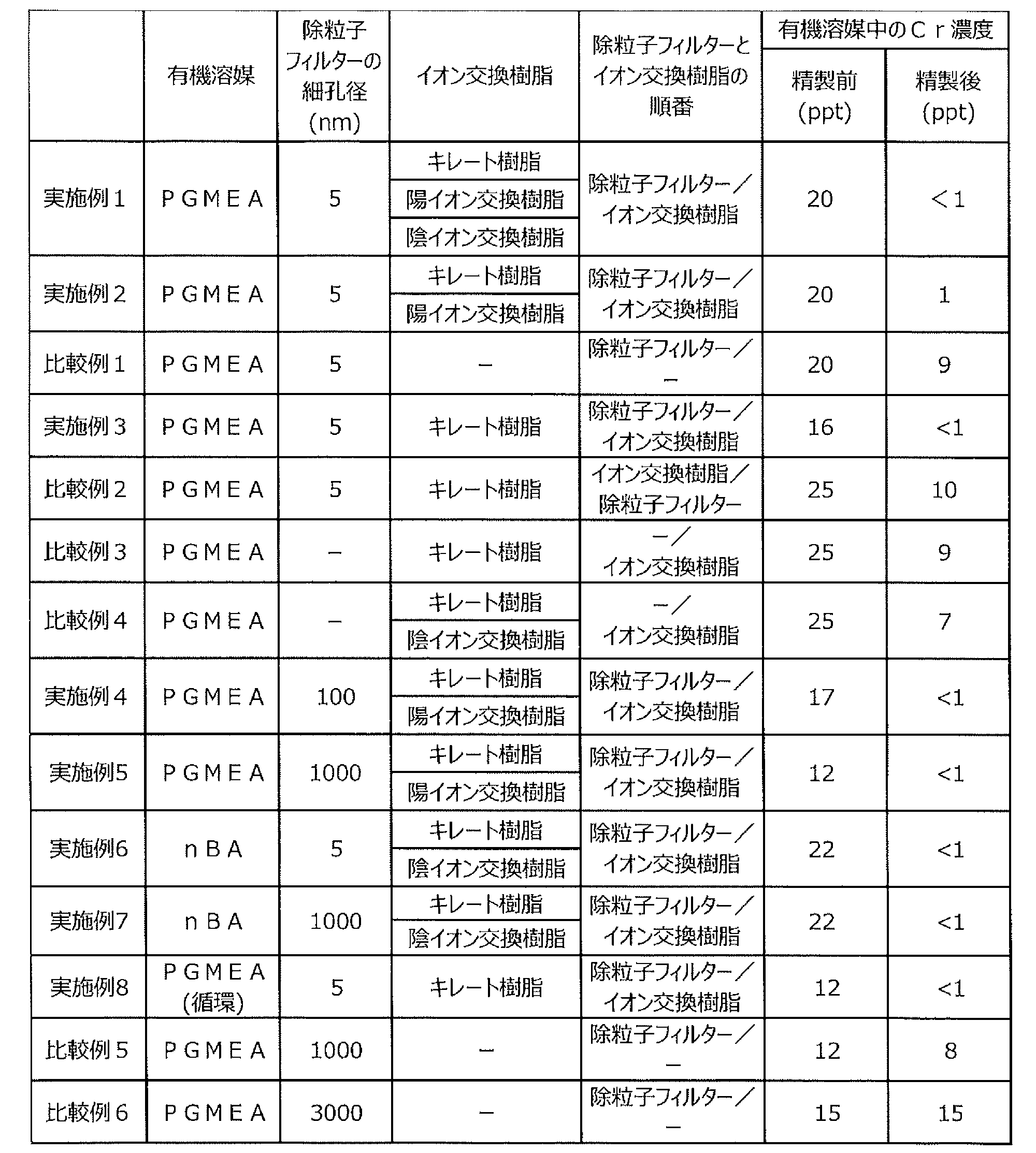
実施例1では、イオン交換樹脂にキレート樹脂、陽イオン交換樹脂及び陰イオン交換樹脂を用いたとき、実施例2では、キレート樹脂及び陽イオン交換樹脂を用いたとき、実施例3では、キレート樹脂のみを用いたとき有機溶媒中のCrを低減できることが明らかとなった。また、実施例4及び実施例5では、除粒子フィルターの細孔径が100nmまたは1000nmのとき、有機溶媒中のCrを低減できることが明らかとなった。さらに、実施例6および実施例7では、有機溶媒にPGMEAではなく、nBAを用いてもCrを低減できることが明らかとなった。実施例8では、PGMEAを循環連続通液処理により精製してもCrを低減できることが明らかとなった。
比較例1では、イオン交換樹脂を用いず、除粒子フィルターのみを用いて有機溶媒を精製してもCrを低減できなかった。比較例2では、イオン交換樹脂、除粒子フィルターの順で有機溶媒を精製してもCrを低減できなかった。比較例3では、除粒子フィルターを用いずイオン交換樹脂としてキレート樹脂のみを用いてもCrを低減できなかった。また、比較例4では、比較例3と同様に除粒子フィルターを用いずイオン交換樹脂のみとし、イオン交換樹脂としてキレート樹脂及び陰イオン交換樹脂を用いてもCrを低減できなかった。比較例5では、除粒子フィルターの細孔径が1000nmのとき、有機溶媒中のCrを一部低減できることが明らかとなった。比較例6では、除粒子フィルターの細孔径が3000nmのとき、有機溶媒中のCrをまったく低減できなかった。
参考例
PGMEA30%:PGME70%(体積比)のシンナー及びIPAについて、イオン交換樹脂のみで精製を行った。使用した樹脂は、キレート樹脂(DS-21)と、陽イオン交換樹脂(DS-1)及び陰イオン交換樹脂(DS-3)の混床を用いた。結果を下記表2に示す。
PGMEA30%:PGME70%(体積比)のシンナー及びIPAについて、イオン交換樹脂のみで精製を行った。使用した樹脂は、キレート樹脂(DS-21)と、陽イオン交換樹脂(DS-1)及び陰イオン交換樹脂(DS-3)の混床を用いた。結果を下記表2に示す。
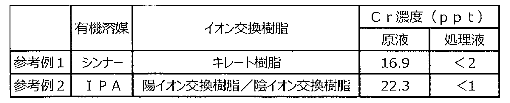
シンナーの場合、キレート樹脂のみでCrを2ppt未満まで低減できる。また、IPAの場合は、陽イオン交換樹脂と陰イオン交換樹脂の混床で検出限界以下までCrを低減できる。
以上、実施形態例を参照して本発明を説明したが、本発明は上記実施形態に限定されるものではない。本発明の構成や詳細には、本発明の範囲内で当業者が理解できる様々な変更を行うことができる。
この出願は、2022年4月26日に出願された日本特許出願特願2022-072311を基礎とする優先権を主張し、その開示の全てをここに取り込む。
この出願は、2022年4月26日に出願された日本特許出願特願2022-072311を基礎とする優先権を主張し、その開示の全てをここに取り込む。
本発明には、以下の方法が含まれる。
[方法1]
有機溶媒中の金属不純物を低減する精製方法であって、除粒子フィルターで有機溶媒をろ過するろ過工程と、前記ろ過工程で得られた有機溶媒をイオン交換体に通液するイオン交換工程とを含むことを特徴とする有機溶媒の精製方法。
[方法2]
前記イオン交換体に通液後の溶液を前記除粒子フィルターに通液することで溶液を循環させて精製する[方法1]記載の有機溶媒の精製方法。
[方法3]
前記イオン交換工程で得られた有機溶媒を、第2の除粒子フィルターでろ過する後ろ過工程を含む[方法1]又は[方法2]に記載の有機溶媒の精製方法。
[方法4]
前記除粒子フィルターの細孔径が、5nm以上1000nm以下である[方法1]~[方法3]のいずれか1項に記載の有機溶媒の精製方法。
[方法5]
前記金属不純物が、Crである[方法1]~[方法4]のいずれか1項に記載の有機溶媒の精製方法。
[方法6]
前記イオン交換体が、イオン交換樹脂である[方法1]~[方法5]のいずれか1項に記載の有機溶媒の精製方法。
[方法7]
前記イオン交換樹脂が、キレート樹脂、陽イオン交換樹脂及び陰イオン交換樹脂のうちいずれか1種の単床または2種以上の混床もしくは複床として使用される[方法6]に記載の有機溶媒の精製方法。
[方法8]
前記イオン交換樹脂は、濃度3質量%の塩酸を体積比25倍量で通過させたときに溶出する全金属不純物溶出量が5μg/mL-R以下の精製イオン交換樹脂である[方法6]又は[方法7]に記載の有機溶媒の精製方法。
[方法9]
前記有機溶媒が、プロピレングリコールモノメチルエーテルアセテートまたはノルマルブチルアセテートである[方法1]~[方法8]のいずれか1項に記載の有機溶媒の精製方法。
[方法1]
有機溶媒中の金属不純物を低減する精製方法であって、除粒子フィルターで有機溶媒をろ過するろ過工程と、前記ろ過工程で得られた有機溶媒をイオン交換体に通液するイオン交換工程とを含むことを特徴とする有機溶媒の精製方法。
[方法2]
前記イオン交換体に通液後の溶液を前記除粒子フィルターに通液することで溶液を循環させて精製する[方法1]記載の有機溶媒の精製方法。
[方法3]
前記イオン交換工程で得られた有機溶媒を、第2の除粒子フィルターでろ過する後ろ過工程を含む[方法1]又は[方法2]に記載の有機溶媒の精製方法。
[方法4]
前記除粒子フィルターの細孔径が、5nm以上1000nm以下である[方法1]~[方法3]のいずれか1項に記載の有機溶媒の精製方法。
[方法5]
前記金属不純物が、Crである[方法1]~[方法4]のいずれか1項に記載の有機溶媒の精製方法。
[方法6]
前記イオン交換体が、イオン交換樹脂である[方法1]~[方法5]のいずれか1項に記載の有機溶媒の精製方法。
[方法7]
前記イオン交換樹脂が、キレート樹脂、陽イオン交換樹脂及び陰イオン交換樹脂のうちいずれか1種の単床または2種以上の混床もしくは複床として使用される[方法6]に記載の有機溶媒の精製方法。
[方法8]
前記イオン交換樹脂は、濃度3質量%の塩酸を体積比25倍量で通過させたときに溶出する全金属不純物溶出量が5μg/mL-R以下の精製イオン交換樹脂である[方法6]又は[方法7]に記載の有機溶媒の精製方法。
[方法9]
前記有機溶媒が、プロピレングリコールモノメチルエーテルアセテートまたはノルマルブチルアセテートである[方法1]~[方法8]のいずれか1項に記載の有機溶媒の精製方法。
本発明には、以下の構成が含まれる。
[構成1]
有機溶媒中の金属不純物を低減する精製装置であって、有機溶媒をろ過するための除粒子フィルターと、前記ろ過後に得られた有機溶媒をイオン交換体に通液して精製する精製手段とを備えることを特徴とする有機溶媒の精製装置。
[構成1]
有機溶媒中の金属不純物を低減する精製装置であって、有機溶媒をろ過するための除粒子フィルターと、前記ろ過後に得られた有機溶媒をイオン交換体に通液して精製する精製手段とを備えることを特徴とする有機溶媒の精製装置。
1 精製対象の有機溶媒
2 貯留タンク
3 除粒子フィルター
4 イオン交換樹脂カラム
5 第2の除粒子フィルター
2 貯留タンク
3 除粒子フィルター
4 イオン交換樹脂カラム
5 第2の除粒子フィルター
Claims (10)
- 有機溶媒中の金属不純物を低減する精製方法であって、除粒子フィルターで有機溶媒をろ過するろ過工程と、前記ろ過工程で得られた有機溶媒をイオン交換体に通液するイオン交換工程とを含むことを特徴とする有機溶媒の精製方法。
- 前記イオン交換体に通液後の溶液を前記除粒子フィルターに通液することで溶液を循環させて精製する請求項1に記載の有機溶媒の精製方法。
- 前記イオン交換工程で得られた有機溶媒を、第2の除粒子フィルターでろ過する後ろ過工程を含む請求項1に記載の有機溶媒の精製方法。
- 前記除粒子フィルターの細孔径が、5nm以上1000nm以下である請求項1~3のいずれか1項に記載の有機溶媒の精製方法。
- 前記金属不純物が、Crである請求項1~3のいずれか1項に記載の有機溶媒の精製方法。
- 前記イオン交換体が、イオン交換樹脂である請求項1~3のいずれか1項に記載の有機溶媒の精製方法。
- 前記イオン交換樹脂が、キレート樹脂、陽イオン交換樹脂及び陰イオン交換樹脂のうちいずれか1種の単床または2種以上の混床もしくは複床として使用される請求項6に記載の有機溶媒の精製方法。
- 前記イオン交換樹脂は、濃度3質量%の塩酸を体積比25倍量で通過させたときに溶出する全金属不純物溶出量が5μg/mL-R以下の精製イオン交換樹脂である請求項7に記載の有機溶媒の精製方法。
- 前記有機溶媒が、プロピレングリコールモノメチルエーテルアセテートまたはノルマルブチルアセテートである請求項1~3のいずれか1項に記載の有機溶媒の精製方法。
- 有機溶媒中の金属不純物を低減する精製装置であって、有機溶媒をろ過するための除粒子フィルターと、前記ろ過後に得られた有機溶媒をイオン交換体に通液して精製する精製手段とを備えることを特徴とする有機溶媒の精製装置。
Priority Applications (1)
| Application Number | Priority Date | Filing Date | Title |
|---|---|---|---|
| JP2024517979A JP7696502B2 (ja) | 2022-04-26 | 2023-04-12 | 有機溶媒の精製方法及び精製装置 |
Applications Claiming Priority (2)
| Application Number | Priority Date | Filing Date | Title |
|---|---|---|---|
| JP2022-072311 | 2022-04-26 | ||
| JP2022072311 | 2022-04-26 |
Publications (1)
| Publication Number | Publication Date |
|---|---|
| WO2023210370A1 true WO2023210370A1 (ja) | 2023-11-02 |
Family
ID=88518437
Family Applications (1)
| Application Number | Title | Priority Date | Filing Date |
|---|---|---|---|
| PCT/JP2023/014876 Ceased WO2023210370A1 (ja) | 2022-04-26 | 2023-04-12 | 有機溶媒の精製方法及び精製装置 |
Country Status (3)
| Country | Link |
|---|---|
| JP (1) | JP7696502B2 (ja) |
| TW (1) | TW202402370A (ja) |
| WO (1) | WO2023210370A1 (ja) |
Cited By (1)
| Publication number | Priority date | Publication date | Assignee | Title |
|---|---|---|---|---|
| JP7849455B1 (ja) * | 2024-12-24 | 2026-04-21 | オルガノ株式会社 | 有機溶媒の精製方法および有機溶媒の精製装置 |
Citations (3)
| Publication number | Priority date | Publication date | Assignee | Title |
|---|---|---|---|---|
| WO2018051716A1 (ja) * | 2016-09-15 | 2018-03-22 | 富士フイルム株式会社 | 有機溶剤の精製方法および有機溶剤の精製装置 |
| CN110204442A (zh) * | 2019-05-23 | 2019-09-06 | 安徽京控环境技术服务有限公司 | 一种从废有机溶剂回收提纯丙二醇甲醚醋酸酯的方法 |
| WO2020013218A1 (ja) * | 2018-07-13 | 2020-01-16 | 富士フイルム株式会社 | 薬液、キット、パターン形成方法、薬液の製造方法及び薬液収容体 |
Family Cites Families (3)
| Publication number | Priority date | Publication date | Assignee | Title |
|---|---|---|---|---|
| IL283235B2 (en) | 2018-11-20 | 2026-03-01 | Fujifilm Electronic Mat Usa Inc | Solvent purification systems and methods |
| TW202200251A (zh) | 2020-03-27 | 2022-01-01 | 美商富士軟片電子材料美國股份有限公司 | 用於純化溶劑之系統及方法 |
| CN114262269B (zh) | 2021-12-30 | 2023-09-26 | 宁波南大光电材料有限公司 | 一种丙二醇甲醚醋酸酯的制备方法 |
-
2023
- 2023-04-12 WO PCT/JP2023/014876 patent/WO2023210370A1/ja not_active Ceased
- 2023-04-12 JP JP2024517979A patent/JP7696502B2/ja active Active
- 2023-04-21 TW TW112114885A patent/TW202402370A/zh unknown
Patent Citations (3)
| Publication number | Priority date | Publication date | Assignee | Title |
|---|---|---|---|---|
| WO2018051716A1 (ja) * | 2016-09-15 | 2018-03-22 | 富士フイルム株式会社 | 有機溶剤の精製方法および有機溶剤の精製装置 |
| WO2020013218A1 (ja) * | 2018-07-13 | 2020-01-16 | 富士フイルム株式会社 | 薬液、キット、パターン形成方法、薬液の製造方法及び薬液収容体 |
| CN110204442A (zh) * | 2019-05-23 | 2019-09-06 | 安徽京控环境技术服务有限公司 | 一种从废有机溶剂回收提纯丙二醇甲醚醋酸酯的方法 |
Cited By (1)
| Publication number | Priority date | Publication date | Assignee | Title |
|---|---|---|---|---|
| JP7849455B1 (ja) * | 2024-12-24 | 2026-04-21 | オルガノ株式会社 | 有機溶媒の精製方法および有機溶媒の精製装置 |
Also Published As
| Publication number | Publication date |
|---|---|
| TW202402370A (zh) | 2024-01-16 |
| JP7696502B2 (ja) | 2025-06-20 |
| JPWO2023210370A1 (ja) | 2023-11-02 |
Similar Documents
| Publication | Publication Date | Title |
|---|---|---|
| JP5717997B2 (ja) | テトラアルキルアンモニウム塩水溶液の製造方法 | |
| CN108430632A (zh) | 用于亲水性有机溶剂的纯化方法 | |
| TWI773881B (zh) | 螯合樹脂之製造方法及製造裝置、以及被處理液之精製方法 | |
| CA3009750C (en) | Purification process for hydrolysable organic solvent | |
| JP4441472B2 (ja) | 陽イオン交換樹脂の含有金属不純物量低減方法 | |
| JP4920019B2 (ja) | 過酸化水素低減方法、過酸化水素低減装置及び超純水製造装置並びに洗浄方法 | |
| JP7577509B2 (ja) | 有機溶媒の精製方法 | |
| JP2026034715A (ja) | 溶媒を精製するためのシステムおよび方法 | |
| JP7696502B2 (ja) | 有機溶媒の精製方法及び精製装置 | |
| JP7645269B2 (ja) | 極性有機溶媒の精製方法、極性有機溶媒の精製装置、分析方法及び精製極性有機溶媒の製造方法 | |
| JP7807270B2 (ja) | 過酸化水素水精製用混合床イオン交換体の調製方法および過酸化水素水の精製方法、並びに重炭酸アンモニウム溶液の精製方法 | |
| CN116419798B (zh) | 含有四烷基铵离子的被处理液的精制方法以及精制装置 | |
| JP2022545155A (ja) | 有機溶媒を精製するためのプロセス | |
| TWI909025B (zh) | 水解性有機溶劑之精製方法及水解性有機溶劑精製用之樹脂之製造方法 | |
| JP7248090B1 (ja) | 有機溶媒の不純物除去方法 | |
| JP7259919B1 (ja) | 有機溶媒の不純物除去方法 | |
| JP7849455B1 (ja) | 有機溶媒の精製方法および有機溶媒の精製装置 | |
| JP7592847B2 (ja) | 非水液の精製方法および精製装置、ならびにイオン交換樹脂の製造方法および前処理装置 |
Legal Events
| Date | Code | Title | Description |
|---|---|---|---|
| 121 | Ep: the epo has been informed by wipo that ep was designated in this application |
Ref document number: 23796114 Country of ref document: EP Kind code of ref document: A1 |
|
| WWE | Wipo information: entry into national phase |
Ref document number: 2024517979 Country of ref document: JP |
|
| NENP | Non-entry into the national phase |
Ref country code: DE |
|
| 122 | Ep: pct application non-entry in european phase |
Ref document number: 23796114 Country of ref document: EP Kind code of ref document: A1 |