WO2023218769A1 - エアバッグ装置 - Google Patents
エアバッグ装置 Download PDFInfo
- Publication number
- WO2023218769A1 WO2023218769A1 PCT/JP2023/011736 JP2023011736W WO2023218769A1 WO 2023218769 A1 WO2023218769 A1 WO 2023218769A1 JP 2023011736 W JP2023011736 W JP 2023011736W WO 2023218769 A1 WO2023218769 A1 WO 2023218769A1
- Authority
- WO
- WIPO (PCT)
- Prior art keywords
- cushion
- chamber
- seat
- main chamber
- airbag device
- Prior art date
- Legal status (The legal status is an assumption and is not a legal conclusion. Google has not performed a legal analysis and makes no representation as to the accuracy of the status listed.)
- Ceased
Links
Images







Classifications
-
- B—PERFORMING OPERATIONS; TRANSPORTING
- B60—VEHICLES IN GENERAL
- B60N—SEATS SPECIALLY ADAPTED FOR VEHICLES; VEHICLE PASSENGER ACCOMMODATION NOT OTHERWISE PROVIDED FOR
- B60N2/00—Seats specially adapted for vehicles; Arrangement or mounting of seats in vehicles
- B60N2/24—Seats specially adapted for vehicles; Arrangement or mounting of seats in vehicles for particular purposes or particular vehicles
- B60N2/42—Seats specially adapted for vehicles; Arrangement or mounting of seats in vehicles for particular purposes or particular vehicles the seat constructed to protect the occupant from the effect of abnormal g-forces, e.g. crash or safety seats
-
- B—PERFORMING OPERATIONS; TRANSPORTING
- B60—VEHICLES IN GENERAL
- B60R—VEHICLES, VEHICLE FITTINGS, OR VEHICLE PARTS, NOT OTHERWISE PROVIDED FOR
- B60R21/00—Arrangements or fittings on vehicles for protecting or preventing injuries to occupants or pedestrians in case of accidents or other traffic risks
- B60R21/02—Occupant safety arrangements or fittings, e.g. crash pads
- B60R21/16—Inflatable occupant restraints or confinements designed to inflate upon impact or impending impact, e.g. air bags
- B60R21/20—Arrangements for storing inflatable members in their non-use or deflated condition; Arrangement or mounting of air bag modules or components
- B60R21/207—Arrangements for storing inflatable members in their non-use or deflated condition; Arrangement or mounting of air bag modules or components in vehicle seats
-
- B—PERFORMING OPERATIONS; TRANSPORTING
- B60—VEHICLES IN GENERAL
- B60R—VEHICLES, VEHICLE FITTINGS, OR VEHICLE PARTS, NOT OTHERWISE PROVIDED FOR
- B60R21/00—Arrangements or fittings on vehicles for protecting or preventing injuries to occupants or pedestrians in case of accidents or other traffic risks
- B60R21/02—Occupant safety arrangements or fittings, e.g. crash pads
- B60R21/16—Inflatable occupant restraints or confinements designed to inflate upon impact or impending impact, e.g. air bags
- B60R21/23—Inflatable members
- B60R21/231—Inflatable members characterised by their shape, construction or spatial configuration
- B60R21/23138—Inflatable members characterised by their shape, construction or spatial configuration specially adapted for side protection
-
- B—PERFORMING OPERATIONS; TRANSPORTING
- B60—VEHICLES IN GENERAL
- B60R—VEHICLES, VEHICLE FITTINGS, OR VEHICLE PARTS, NOT OTHERWISE PROVIDED FOR
- B60R21/00—Arrangements or fittings on vehicles for protecting or preventing injuries to occupants or pedestrians in case of accidents or other traffic risks
- B60R21/02—Occupant safety arrangements or fittings, e.g. crash pads
- B60R21/16—Inflatable occupant restraints or confinements designed to inflate upon impact or impending impact, e.g. air bags
- B60R21/23—Inflatable members
- B60R21/231—Inflatable members characterised by their shape, construction or spatial configuration
- B60R21/233—Inflatable members characterised by their shape, construction or spatial configuration comprising a plurality of individual compartments; comprising two or more bag-like members, one within the other
-
- B—PERFORMING OPERATIONS; TRANSPORTING
- B60—VEHICLES IN GENERAL
- B60R—VEHICLES, VEHICLE FITTINGS, OR VEHICLE PARTS, NOT OTHERWISE PROVIDED FOR
- B60R21/00—Arrangements or fittings on vehicles for protecting or preventing injuries to occupants or pedestrians in case of accidents or other traffic risks
- B60R21/02—Occupant safety arrangements or fittings, e.g. crash pads
- B60R21/16—Inflatable occupant restraints or confinements designed to inflate upon impact or impending impact, e.g. air bags
- B60R21/26—Inflatable occupant restraints or confinements designed to inflate upon impact or impending impact, e.g. air bags characterised by the inflation fluid source or means to control inflation fluid flow
-
- B—PERFORMING OPERATIONS; TRANSPORTING
- B60—VEHICLES IN GENERAL
- B60R—VEHICLES, VEHICLE FITTINGS, OR VEHICLE PARTS, NOT OTHERWISE PROVIDED FOR
- B60R21/00—Arrangements or fittings on vehicles for protecting or preventing injuries to occupants or pedestrians in case of accidents or other traffic risks
- B60R21/02—Occupant safety arrangements or fittings, e.g. crash pads
- B60R21/16—Inflatable occupant restraints or confinements designed to inflate upon impact or impending impact, e.g. air bags
- B60R21/23—Inflatable members
- B60R21/231—Inflatable members characterised by their shape, construction or spatial configuration
- B60R21/23138—Inflatable members characterised by their shape, construction or spatial configuration specially adapted for side protection
- B60R2021/23146—Inflatable members characterised by their shape, construction or spatial configuration specially adapted for side protection seat mounted
-
- B—PERFORMING OPERATIONS; TRANSPORTING
- B60—VEHICLES IN GENERAL
- B60R—VEHICLES, VEHICLE FITTINGS, OR VEHICLE PARTS, NOT OTHERWISE PROVIDED FOR
- B60R21/00—Arrangements or fittings on vehicles for protecting or preventing injuries to occupants or pedestrians in case of accidents or other traffic risks
- B60R21/02—Occupant safety arrangements or fittings, e.g. crash pads
- B60R21/16—Inflatable occupant restraints or confinements designed to inflate upon impact or impending impact, e.g. air bags
- B60R21/23—Inflatable members
- B60R21/231—Inflatable members characterised by their shape, construction or spatial configuration
- B60R2021/23161—Inflatable members characterised by their shape, construction or spatial configuration specially adapted for protecting at least two passengers, e.g. preventing them from hitting each other
-
- B—PERFORMING OPERATIONS; TRANSPORTING
- B60—VEHICLES IN GENERAL
- B60R—VEHICLES, VEHICLE FITTINGS, OR VEHICLE PARTS, NOT OTHERWISE PROVIDED FOR
- B60R21/00—Arrangements or fittings on vehicles for protecting or preventing injuries to occupants or pedestrians in case of accidents or other traffic risks
- B60R21/02—Occupant safety arrangements or fittings, e.g. crash pads
- B60R21/16—Inflatable occupant restraints or confinements designed to inflate upon impact or impending impact, e.g. air bags
- B60R21/23—Inflatable members
- B60R21/231—Inflatable members characterised by their shape, construction or spatial configuration
- B60R21/233—Inflatable members characterised by their shape, construction or spatial configuration comprising a plurality of individual compartments; comprising two or more bag-like members, one within the other
- B60R2021/23308—Inflatable members characterised by their shape, construction or spatial configuration comprising a plurality of individual compartments; comprising two or more bag-like members, one within the other the individual compartments defining the external shape of the bag
-
- B—PERFORMING OPERATIONS; TRANSPORTING
- B60—VEHICLES IN GENERAL
- B60R—VEHICLES, VEHICLE FITTINGS, OR VEHICLE PARTS, NOT OTHERWISE PROVIDED FOR
- B60R21/00—Arrangements or fittings on vehicles for protecting or preventing injuries to occupants or pedestrians in case of accidents or other traffic risks
- B60R21/02—Occupant safety arrangements or fittings, e.g. crash pads
- B60R21/16—Inflatable occupant restraints or confinements designed to inflate upon impact or impending impact, e.g. air bags
- B60R21/23—Inflatable members
- B60R21/231—Inflatable members characterised by their shape, construction or spatial configuration
- B60R21/233—Inflatable members characterised by their shape, construction or spatial configuration comprising a plurality of individual compartments; comprising two or more bag-like members, one within the other
- B60R2021/23324—Inner walls crating separate compartments, e.g. communicating with vents
-
- B—PERFORMING OPERATIONS; TRANSPORTING
- B60—VEHICLES IN GENERAL
- B60R—VEHICLES, VEHICLE FITTINGS, OR VEHICLE PARTS, NOT OTHERWISE PROVIDED FOR
- B60R21/00—Arrangements or fittings on vehicles for protecting or preventing injuries to occupants or pedestrians in case of accidents or other traffic risks
- B60R21/02—Occupant safety arrangements or fittings, e.g. crash pads
- B60R21/16—Inflatable occupant restraints or confinements designed to inflate upon impact or impending impact, e.g. air bags
- B60R21/23—Inflatable members
- B60R21/231—Inflatable members characterised by their shape, construction or spatial configuration
- B60R21/2334—Expansion control features
- B60R21/2338—Tethers
- B60R2021/23386—External tether means
Definitions
- the present invention provides, for example, the center side in the width direction (hereinafter sometimes referred to as far side) of the backrest of one of the seats arranged in the width direction of the vehicle in the vehicle interior.
- This invention relates to an airbag device installed on a side surface.
- Airbag devices that have the ability to restrain an occupant in response to impacts from the far side have been known.
- a cushion is inflated and deployed in the center of the vehicle interior to protect the far side of the occupant.
- Patent Document 1 describes an inter-seat airbag device provided in a console box installed between a driver's seat and a passenger seat.
- the cushion of this inter-seat airbag device has a main bag that inflates and deploys in an I-shape when viewed from the front, and when gas is supplied through the main bag, the cushion protrudes from the vertical center of the main bag toward the passenger seat side and inflates and deploys. Equipped with a secondary bag.
- conventional seat-to-seat airbag devices assume that a console box is installed between the driver's seat and the passenger's seat, and that the height of the console box is higher than the top surface of the seat cushion.
- the shape of the cushion is defined as follows. Specifically, the cushions of conventional inter-seat airbag devices are often shaped so that the bottom surface of the cushion comes into contact with the top surface of the console box when inflated and deployed. With such a shape, when the cushion is inflated and deployed, a reaction force is obtained from the console box, and the console box can be used as support.
- the shape of the cushion should be improved in order to improve performance in far-side collisions in vehicles with low (or no) console boxes. considered desirable.
- the present invention has been made in view of these circumstances, and even in vehicles where the console box is lower than the top surface of the seat cushion or in a vehicle without a console box, the expansion behavior of the cushion is stabilized during inflation and expansion.
- the purpose of this invention is to realize an airbag device in which a cushion does not tilt when an occupant is restrained.
- the present invention is an airbag device that is installed on the side surface of the backrest of one of the seats arranged in the width direction of a vehicle on the center side in the width direction.
- An airbag device includes a cushion and an inflator that injects gas to inflate the cushion, and the cushion has a main chamber that is inflated and deployed on one side of a seat, and a part of the main chamber. a lower chamber extending downward from the upper surface of the console box or the vehicle, the lower end of the lower chamber being at a lower position than the upper surface of the seat cushion of the seat when inflated and deployed. It is formed so that it can come into contact with the floor surface.
- the main chamber includes a first part that receives the side part of an occupant seated on one of the seats arranged in a row in the width direction of the vehicle, and a first part that receives the side part of an occupant seated on one of the seats arranged in a row in the width direction of the vehicle;
- the lower chamber has a second portion that receives the side portion of the occupant, and a central portion provided between the first portion and the second portion, and the lower chamber extends downward from the central portion. But that's fine.
- the main chamber has a first portion, a central portion, and a second portion that are continuously formed integrally, and the lower chamber may be formed as a separate chamber separated from the main chamber. .
- the main chamber and the lower chamber may be configured to communicate through the first vent hole.
- the present invention may be configured such that the inflator is attached to a main chamber, and a portion of the gas injected from the inflator is supplied from the main chamber to the lower chamber through the first vent hole.
- the central portion protrudes at least further forward of the vehicle than the first and second portions to receive the head of the occupant and the occupant moving diagonally forward. Possible protrusions may also be provided.
- the main chamber has a first portion, a central portion, and a second portion that are continuously formed integrally, and the protruding portion may be formed in a separate chamber separated from the main chamber. .
- the main chamber and the protrusion may be configured to communicate through the second vent hole.
- the present invention may include a connecting member that connects the front lower part of the protrusion and the bottom front part of the lower chamber.
- the present invention may include a connecting member that connects the lower front portion of the protrusion and the lower front portion of the central portion.
- the cushion of the airbag device of the present invention has a main chamber that inflates and deploys toward one side of the seat, specifically toward the far side of the seat, and also extends downwardly from a portion of the main chamber. It has a lower chamber extending towards it.
- the lower chamber is configured in such a shape that, when inflated and deployed, the lower end of the lower chamber can come into contact with the upper surface of the console box or the floor of the vehicle, which is located at a lower position than the upper surface of the seat cushion of the seat.
- the lower chamber that expands and deploys during a side collision supports the lower part of the main chamber that protects the side of the occupant. Due to the presence of this support portion, in the present invention, when the cushion is inflated and deployed, vertical swinging is reduced, and the deployment behavior of the cushion is stabilized. Further, according to the present invention, it is possible to prevent the cushion from tilting upon completion of inflation and deployment.
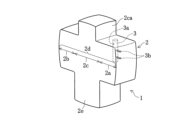
- FIG. 1A is a perspective view of a cushion in a state in which inflation and deployment have been completed in an airbag device according to an embodiment, viewed from an oblique direction.
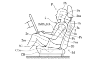
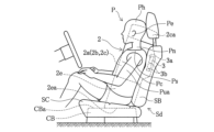
- FIG. 1B is a view from the side of the vehicle in which the cushion is inflated and deployed in the airbag device of FIG. 1A.
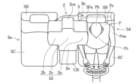
- FIG. 1C is a diagram of the airbag device of FIG. 1A in which the cushion is inflated and deployed, viewed from above the vehicle.
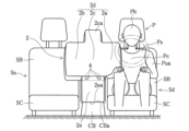
- FIG. 1D is a view of the airbag device of FIG. 1A in a state where the cushion is inflated and deployed, as seen from the front of the vehicle.
- FIG. 1A is a perspective view of a cushion in a state in which inflation and deployment have been completed in an airbag device according to an embodiment, viewed from an oblique direction.
- FIG. 1B is a view from the side of the vehicle in which the cushion is inflated and deployed in the airbag device of FIG. 1A.
- FIG. 1C is a diagram of
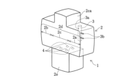
- FIG. 2A is a perspective view of a cushion in a state in which inflation and deployment have been completed in an airbag device according to a first modification of the embodiment, viewed from an oblique direction.
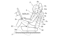
- FIG. 2B is a view from the side of the vehicle in which the cushion is inflated and deployed in the airbag device of FIG. 2A.
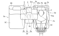
- FIG. 2C is a view of the airbag device of FIG. 2A in a state where the cushion is inflated and deployed, viewed from above the vehicle.
- FIG. 2D is a view of the airbag device of FIG. 2A in a state where the cushion is inflated and deployed, as seen from the front of the vehicle.
- FIG. 3A is a perspective view of a cushion in a state in which inflation and deployment have been completed in an airbag device according to a second modification of the embodiment, viewed from an oblique direction.
- FIG. 3B is a view from the side of the vehicle in which the cushion is inflated and deployed in the airbag device of FIG. 3A.
- FIG. 3C is a view from above the vehicle in which the cushion is inflated and deployed in the airbag device of FIG. 3A.
- FIG. 3D is a view of the airbag device of FIG. 3A in a state where the cushion is inflated and deployed, as seen from the front of the vehicle.
- FIG. 3B is a view from the side of the vehicle in which the cushion is inflated and deployed in the airbag device of FIG. 3A.
- FIG. 3C is a view from above the vehicle in which the cushion is inflated and deployed in the airbag device of FIG. 3A.
- FIG. 3D is a view of the airbag device of FIG. 3A in
- FIG. 4A is a perspective view of a cushion in a state in which inflation and deployment have been completed in an airbag device according to a third modification of the embodiment, viewed from an oblique direction.
- FIG. 4B is a view from the side of the vehicle in which the cushion is inflated and deployed in the airbag device of FIG. 4A.
- FIG. 4C is a diagram of the airbag device of FIG. 4A in which the cushion is inflated and deployed, viewed from above the vehicle.
- FIG. 4D is a view of the airbag device of FIG. 4A in a state where the cushion is inflated and deployed, as seen from the front of the vehicle.
- FIG. 4B is a view from the side of the vehicle in which the cushion is inflated and deployed in the airbag device of FIG. 4A.
- FIG. 4C is a diagram of the airbag device of FIG. 4A in which the cushion is inflated and deployed, viewed from above the vehicle.
- FIG. 4D is a view of the airbag device of
- FIG. 5A is a perspective view of a cushion in a state in which inflation and deployment have been completed in an airbag device according to a fourth modification of the embodiment, viewed from an oblique direction.
- FIG. 5B is a view from the side of the vehicle in which the cushion is inflated and deployed in the airbag device of FIG. 5A.
- FIG. 6A is a perspective view of a cushion in a state in which inflation and deployment have been completed in an airbag device according to a fifth modification of the embodiment, viewed from an oblique direction.
- FIG. 6B is a view from the side of the vehicle in which the cushion is inflated and deployed in the airbag device of FIG. 6A.
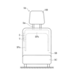
- FIG. 7 is a front view of the seat with the cushion stored.
- the term "occupant” refers to, for example, a dummy for frontal collision tests (Hybrid III AM50/NHTSA [National Highway Traffic Safety Administration] standards [49CFR Part572 Subpart E and O]).
- Hybrid III AM50/NHTSA National Highway Traffic Safety Administration
- the present invention is also applicable to other human dummies.
- upper and “upper side” refer to the direction of the head of the occupant P seated in the regular position of the seats Sd and Sn
- lower and “lower side” refer to the direction toward the feet of the occupant P.
- the "regular position” refers to a position where the back of the occupant P vertically contacts the backrest portion SB at the center position in the left-right direction of each seat cushion SC in the seats Sd and Sn.
- front and “front side” may mean the front direction of the occupant P seated in the normal position of seats Sd and Sn
- “rear” and “rear side” may mean the back direction of the occupant P.
- left and “left side” may refer to the left hand direction of the occupant P seated in the regular positions of the seats Sd and Sn
- “right” and “right side” may refer to the right hand direction of the occupant P.
- the inner side surface of the far side of the backrest part SB of one of the two seats (for example, the driver's seat Sd and the passenger seat Sn) arranged in the width direction of the vehicle.
- This is an airbag device 1 to be installed.
- 1A to 1D show an example in which the airbag device 1 is provided on the driver's seat Sd side. Below, before explaining the airbag device 1, the seat (driver's seat Sd) on which the airbag device 1 is mounted will be explained.
- the driver's seat Sd includes a seat cushion SC and a backrest portion SB.
- a headrest HR is attached to the upper end of the backrest portion SB via a rod-shaped support member Sm.
- the driver's seat Sd may have a backrest portion SB and a headrest HR integrally formed.
- FIG. 7 there is a door (not shown) on the right side of the page.
- the far side is the side of the driver's seat Sd that is far from the door.
- the seat cushion SC has a pad provided above a seat pan (not shown), and the pad is covered with a skin material.
- a pad is provided on the front side of the seat frames SFa and SFb, and the pad is covered with a skin material.
- the cushion 2 can be stored in the seat Sd by being rolled up or folded into a bellows shape when placed flat.
- the cushion 2 in the stowed form is stored along the side SFa of the seat frame of the seat Sd, as shown in FIG.
- the cushion 2 is stored within the far side of the seat Sd.
- a fixing device T is used to fix the cushion 2 in the storage form to the far side side SFa of the seat frame. Therefore, displacement of the cushion 2 can be suppressed in the event of a collision or the like.
- the arrangement and number of fixtures T are not limited to this embodiment.
- the airbag device 1 includes a cushion 2 and an inflator 3 (see FIG. 1C).
- the cushion 2 is a bag made of cloth, which is constructed by preparing in advance a required number of base fabrics of a desired shape and sewing predetermined locations such as the outer periphery of these base fabrics.
- the inflator 3 is a device that injects gas that inflates the cushion 2.
- a cylindrical inflator 3 is disposed inside the cushion 2, which receives a signal from a sensor and jets gas into the cushion 2 from a hole 3a provided on the outer surface thereof.
- the cushion 2 is attached to the inner side of the backrest part SB using two stud bolts 3b that are provided in a protruding manner at an appropriate interval in the longitudinal direction on the outer surface opposite to the hole 3a of the inflator 3. It is attached to the side SFa of the frame.
- the fixture T for fixing the cushion 2 can be omitted.
- the inflator 3 is fixed to the side part SFa of the seat frame by stud bolts 3b.
- the stud bolt 3b is passed through the insertion hole of the storage portion, so that the storage portion is also fixed to the side portion SFa of the seat frame.
- the main chamber 2d of the cushion 2 is inflated and deployed so that it rides on the front of the driver's seat Sd and the front of the passenger's seat Sn, so that the main chamber 2d of the cushion 2 is expanded to the far side of the passenger P seated on the driver's seat Sd and/or the front passenger's seat Sn. It has a first part 2a and a second part 2b that protect the parts, and a central part 2c that expands and deploys between the first part 2a and the second part 2b. Specifically, the first part 2a restrains the side part of the occupant P seated in the driver's seat Sd, and the second part 2b restrains the side part of the passenger P seated in the passenger seat Sn. It is something.
- first portion 2a, second portion 2b, and central portion 2c are not strict.
- vertical dimensions, longitudinal dimensions, and lateral dimensions of the main chamber 2d are not limited to those illustrated in the drawings, and can be adjusted in accordance with the shape and arrangement of the seats Sd and Sn.
- the first portion 2a, the second portion 2b, and the central portion 2c are integrally formed in one main chamber 2d.
- the main chamber 2d When viewed from the front side of the vehicle, the main chamber 2d has a shape in which the central portion 2c has an extension portion 2ca that extends upward from the first portion 2a and the second portion 2b, and has a required thickness in the longitudinal direction of the vehicle. It is formed by joining an appropriate number of base fabric panels so that it has the following properties.
- the first portion 2a and the second portion 2b have lengths in the vertical and longitudinal directions that can receive the sides of the torso of the occupant P, such as the shoulder Ps, chest Pc, and upper arm Pua.
- the central portion 2c also has an extension portion 2ca that extends in the vertical and longitudinal directions so as to be able to receive the rear side of the head Ph from the neck Pn to the ears Pe of the occupant P, for example. It has a length.
- the inflator 3 receives a signal from the sensor and injects gas into the main chamber 2d from the hole 3a provided on its outer surface.
- the main chamber 2d is expanded and expanded.
- the first portion 2a and second portion 2b which expand and deploy and ride on the front of the driver's seat Sd and the front passenger seat Sn, may damage, for example, the shoulders Ps, chest Pc, and upper arms of the occupant P who moves due to the impact. part Pua, and restrains the movement of the occupant P.
- the height of the console box CB is higher than the upper surface of the seat cushion SC of the seats Sd and Sn, even if the cushion 2 is composed of only the main chamber 2d, it can be inflated and deployed.
- the bottom surface of the main chamber 2d can be supported by the top surface of the console box CB.
- the bottom surface of the main chamber 2d cannot be supported when the main chamber 2d is inflated and deployed.
- the cushion 2 of this embodiment includes a lower chamber 2e extending downward from a part of the main chamber 2d. Specifically, the lower chamber 2e extends downward from the central portion 2c of the main chamber 2d.
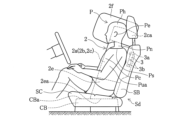
- the lower chamber 2e When the lower chamber 2e is inflated and deployed, the lower end 2ea of the lower chamber 2e contacts the upper surface CBa of the console box CB, which is located at a lower position than the upper surface of the seat cushion SC of the seat Sd, as shown in FIGS. 1B and 1D. It is designed to be possible.
- the lower chamber 2e has a generally rectangular parallelepiped shape, and the length in the vertical direction of the lower chamber 2e is defined so that the bottom surface 2ea of the lower chamber 2e reaches and contacts the upper surface CBa of the console box CB during inflation and deployment.
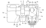
- the width of the lower chamber 2e in the left-right direction is the same as the width in the left-right direction of the console box CB installed between the driver's seat Sd and the passenger seat Sn.
- the width of the lower chamber 2e in the left-right direction may be slightly longer than the width of the console box CB in the left-right direction, so that the width just fits in the space between the driver's seat Sd and the passenger seat Sn without creating a gap. However, it may be shorter than the width of the console box CB in the left-right direction.
- the vertical dimensions, longitudinal dimensions, and lateral dimensions of the lower chamber 2e are not limited to those illustrated in each figure, and can be adjusted as appropriate according to the shapes, installation positions, etc. of the seats Sd and Sn. .
- the lower chamber 2e is formed by joining an appropriate number of base fabric panels so as to project downward from the main chamber 2d.
- the lower chamber 2e of this embodiment is formed integrally with the main chamber 2d, forming one bag.
- a gas guide may be provided in the storage portion of the inflator 3.
- the gas guide may be configured to have a first outlet that opens to the main chamber 2d and a second outlet that opens to the lower chamber 2e as outlets for the gas injected from the inflator 3.
- the cushion 2 expands and deploys toward the side of the far side of one of the seats Sd and Sn to suppress the movement of the occupant P who attempts to move in the direction in which the impact is applied.
- a lower chamber 2e extending downward from the central portion 2c of the main chamber 2d.
- the lower chamber 2e has a shape that allows the lower end 2ea of the lower chamber 2e to contact the upper surface CBa of the console box CB, which is located at a lower position than the upper surface of the seat cushion SC of the seats Sd and Sn, when inflated and deployed. It is configured.
- the present embodiment is applied to a vehicle in which the height of the console box CB is lower than the upper surface of the seat cushion SC of the seats Sd and Sn, the space in the portion lower than the upper surface of the seat cushion SC is The lower chamber 2e expands and expands downward to fill the area.
- the inflated and deployed lower chamber 2e supports the lower part of the main chamber 2d that protects the side part of the occupant P.
- the vertical swing is reduced, and the deployment behavior of the cushion 2 is stabilized.
- the inflated and deployed lower chamber 2e supports the lower part of the main chamber 2d that protects the side part of the occupant P. Therefore, according to the present embodiment, it is possible to prevent the cushion 2 from tilting upon completion of inflation and deployment.
- the airbag device 1 of this embodiment has stable deployment behavior of the cushion 2 and exhibits high restraint performance against a side collision from the far side.
- the main chamber 2d includes a first portion 2a that restrains the side portion of the occupant P seated in the driver's seat Sd, and a second portion 2a that restrains the side portion of the occupant P seated in the passenger seat Sn. Both portions 2b are provided. Therefore, the occupant P in either seat Sd or Sn can be appropriately protected, and the restraint performance for the occupant P can be improved. Further, even when the occupant P in the driver's seat Sd moves to the opposite side from the initial stage of the collision due to the impact force of the collision, for example, a collision with the occupant in the passenger seat Sn can be effectively avoided.
- the lower chamber 2e is formed as a separate chamber separated from the main chamber 2d.
- the lower chamber 2e is formed into a rectangular parallelepiped by joining an appropriate number of base fabric panels so that it projects downward from the main chamber 2d, and is joined to the lower surface of the main chamber 2d.
- the lower chamber 2e of this modification communicates with the main chamber 2d via a first vent hole 4 provided on the lower surface of the central portion 2c of the main chamber 2d.
- the inflator 3 that receives a signal from the sensor blows gas into the main chamber 2d from the hole 3a provided on its outer surface to inflate and deploy the main chamber 2d. After the main chamber 2d expands and deploys, gas flows into the lower chamber 2e from the first vent hole 4, and the lower chamber 2e expands and deploys.
- the number of first vent holes 4 to be provided and the size (inner diameter) of each hole may be designed in consideration of the timing of expanding and deploying the lower chamber 2e. If the total opening area of the first vent holes 4 is made sufficiently large, gas can be quickly supplied to the lower chamber 2e almost simultaneously with the expansion and development of the main chamber 2d, and the lower chamber 2e can be expanded quickly. can be done. Depending on design requirements, the total opening area of the first vent hole 4 may be adjusted to be slightly smaller to reduce the required time lag between the expansion and expansion of the main chamber 2d and the lower chamber 2e. It can also be caused.
- the lower chamber 2e expands and deploys downward so as to fill the space below the upper surface of the seat cushion SC. Since the lower chamber 2e serves as a supporting portion, the main chamber 2d is stabilized during inflation and deployment.
- the lower chamber 2e is configured in such a shape that the lower end 2ea of the lower chamber 2e can come into contact with the floor surface F of the vehicle during inflation and deployment.
- the shape of the lower chamber 2e is a rectangular parallelepiped that is slightly longer in the vertical direction than in the above embodiment.
- the length of the lower chamber 2e in the vertical direction is determined so that the bottom surface of the lower chamber 2e reaches and contacts the floor surface F during inflation and deployment.
- the width of the lower chamber 2e in the left-right direction is set so as to fit in the space between the driver's seat Sd and the passenger seat Sn without creating a gap.
- the inflator 3 when a shock is applied to the vehicle due to a collision or the like, the inflator 3 receives a signal from the sensor and injects gas into the main chamber 2d, causing the main chamber 2d to expand and expand. Further, a part of the gas injected into the main chamber 2d is supplied to the lower chamber 2e via the first vent hole 4. As a result, the lower chamber 2e expands and deploys downward so as to fill the entire space where the console box CB would be present in a typical vehicle. Since the lower chamber 2e serves as a supporting portion, the main chamber 2d is stabilized during inflation and deployment.
- the airbag device 1 exhibits occupant restraint performance in response to a side collision.
- the lower chamber 2e is formed as a separate chamber from the main chamber 2d, but the lower chamber 2e may be formed integrally with the main chamber 2d.
- the extension portion 2ca of the central portion 2c receives the head Ph of the occupant P.
- further improvement in performance may be required so that the entire head Ph of the occupant P can be received more reliably from the initial stage of a vehicle collision to the final stage when the impact of the collision is gone.
- the central portion 2c of the cushion 2 is provided with at least a larger portion of the vehicle than the first portion 2a and the second portion 2b when inflated and deployed.
- a protrusion 2f is formed that protrudes in the front direction and can receive the entire head Ph of the occupant P.
- the protruding portion 2f also has a function of catching the occupant P who moves diagonally forward in the event of a collision from an oblique direction. Note that the configuration of the lower chamber 2e in this modification is the same as that in the first modification, so a description thereof will be omitted.
- the protruding portion 2f is configured to cover the upper surface of the extension portion 2ca so that its upper surface is above the top of the head of the occupant P seated in the driver's seat Sd or passenger seat Sn. Provided for. Then, an appropriate number of base fabric panels are sewn to form the covering portion and the portion protruding forward from the front surface of the extension portion 2ca.
- the protruding portion 2f is formed in a separate chamber separated from the main chamber 2d.
- the protrusion 2f communicates with the main chamber 2d via a second vent hole 5 provided on the upper surface of the extension 2ca.
- the size (inner diameter) of the second vent hole 5 is such that gas flows into the protrusion 2f in the latter half of the expansion and deployment of the main chamber 2d, and there is a time lag between the expansion and deployment of the main chamber 2d and the expansion and deployment of the protrusion 2f.
- the size is such that it will occur.
- the inflator 3 that receives the signal from the sensor blows out gas into the main chamber 2d from the hole 3a provided on the outer surface of the inflator 3.
- the main chamber 2d is expanded and expanded.
- the main chamber 2d After the main chamber 2d expands and develops to some extent, gas flows into the protrusion 2f from the second vent hole 5, and the protrusion 2f expands and develops.
- the main chamber 2d which has less time to protect the occupant P from the collision, can be inflated and deployed before the protrusion 2f.
- This inflated and deployed protrusion 2f prevents the entire occupant P and his/her head Ph from moving due to the impact, not only when an impact is applied from the side of the occupant P, but also when an impact is applied from diagonally in front of the occupant P. can be accepted with certainty.
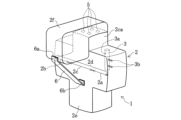
- the tether 6 is a string-like or thin band-like member.
- the same material as the base fabric constituting the cushion 2 may be used for the tether 6.
- a non-stretchable material can be suitably used for the tether 6, but a stretchable material can also be used.
- the protrusion 2f is stabilized by connecting the protrusion 2f and the lower chamber 2e with the tether 6, so that when a collision occurs from the side, the portion of the extension 2ca of the protrusion 2f that expands and deploys in the forward direction Even if the head Ph of the occupant P moves and causes a collision, the movement of the head Ph can be effectively suppressed.
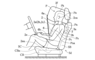
- the fifth modification in which the attachment position of the other end 6b of the tether 6 is changed also provides the same effects as the fourth modification.
- the attachment position of the one end 6a of the tether 5 to the protrusion 2f can be changed from the front lower part of the protrusion 2f to the bottom front part.
- the same effects as in the fourth modification and the fifth modification are achieved.
- the configuration and function of the lower chamber 2e in this modification are the same as in the first modification.
- the bottom surface of the lower chamber 2e may be provided with a non-slip portion having a larger coefficient of friction than the surface of the base fabric panel constituting the lower chamber 2e.
- a non-slip portion with a large coefficient of friction on the bottom surface of the lower chamber 2e, when the lower chamber 2e expands and deploys and the bottom surface of the lower chamber 2e comes into contact with the top surface of the console box CB or the floor surface F of the passenger compartment. , the bottom surface of the lower chamber 2e becomes less slippery and easier to stay in place.
- the anti-slip portion having such a large coefficient of friction can be provided by applying a resin coating to the bottom surface of the lower chamber 2e.
- the anti-slip portion may be provided by sewing a patch to the bottom of the lower chamber 2e.
- the first portion 2a, second portion 2b, and central portion 2c of the main chamber 2d may be formed by a plurality of divided chambers.
- the gas injected from the inflator 3 may be directly sent to the first portion 2a, second portion 2b, and central portion 2c so that the gas can be inflated and deployed without time lag.
- the configuration shown in the first modification and the configuration shown in the third modification may be combined. That is, the lower chamber 2e is configured as a separate chamber separated from the main chamber 2d, and is communicated with the main chamber 2d via the first vent hole 4 provided on the lower surface of the central portion 2c, and the protruding portion 2f is It may be configured as a separate chamber separated from the main chamber 2d and communicated with the main chamber 2d via a second vent hole 5 provided on the upper surface of the extension portion 2ca of the central portion 2c.
- the airbag device 1 may be housed in the far side side portion of the passenger seat Sn.
- the second vent hole 5 may be provided on the front surface of the extension portion 2ca in addition to the upper surface. Alternatively, the second vent hole 5 may be provided only on the front surface of the extension portion 2ca.
- the cushion 2 and the tether 6 are not limited to sewing, and may be joined by any method such as gluing or welding, as long as a predetermined strength can be obtained.
- the cushion 2 is not limited to one in which an appropriate number of base fabric panels are joined by sewing or the like, but may be formed using a so-called "one-piece weaving" technique.
- the airbag device 1 is not limited to the front seat of the vehicle, but may be installed on the rear seat.
- the airbag device 1 may be attached to the seats in the second or third row.
- the present invention is applicable to an airbag device that protects the side of an occupant.
- Airbag device cushion 2a First part 2b Second part 2c Central part 2ca Extension part 2d Main chamber 2e Lower chamber 2ea Lower end part 2f Projection part 3 Inflator 4 First vent hole 5 Second vent hole 6 Connecting member (tether) Sd seat (driver's seat) Sn seat (passenger seat) SB Backrest SC Seat cushion
Landscapes
- Engineering & Computer Science (AREA)
- Mechanical Engineering (AREA)
- Physics & Mathematics (AREA)
- Fluid Mechanics (AREA)
- Aviation & Aerospace Engineering (AREA)
- Transportation (AREA)
- Air Bags (AREA)
Abstract
Description
運転席Sdは、図7に示すように、シートクッションSCと、背もたれ部SBとを備えている。背もたれ部SBの上端部には、棒状の支持部材Smを介して、ヘッドレストHRが取り付けられている。運転席Sdは、背もたれ部SBとヘッドレストHRが一体的に形成されたものであってもよい。図7では、紙面右側にドア(不図示)がある。運転席Sdのドアから遠い側がファーサイドである。
エアバッグ装置1は、クッション2と、インフレータ3(図1C参照)を備えている。クッション2は、所要の形状の基布を必要数あらかじめ準備し、これらの基布の外周部など所定の箇所を縫製することにより構成された布製の袋体である。インフレータ3は、クッション2を膨張させるガスを噴射する装置である。
膨張展開が完了した状態(以下、「膨張完了状態」と言う。)のクッション2の構成について、図1A~図1Dを参照しながら説明を行う。なお、図1Bにおいて、乗員Pは正規の位置に着座しているものとしている。
本実施形態では、クッション2が、座席Sd,Snの一方のファーサイドの側部の側に膨張展開して衝撃が加わった方向に移動しようとする乗員Pの移動を抑制するメインチャンバ2dに加え、メインチャンバ2dの中央部分2cから下方に向かって延設された下方チャンバ2eを備えている。そして、下方チャンバ2eは、膨張展開時、下方チャンバ2eの下端部2eaが、座席Sd,SnのシートクッションSCの上面よりも低い位置にあるコンソールボックスCBの上部表面CBaに接触可能となる形状に構成されている。
本変形例では、図2A~図2Dに示すように、下方チャンバ2eは、メインチャンバ2dとは分離された別チャンバで形成している。下方チャンバ2eは、メインチャンバ2dから下方向に突出した形状となるように、適数枚の基布パネルを接合して直方体状に形成した上で、メインチャンバ2dの下面と接合している。本変形例の下方チャンバ2eは、メインチャンバ2dの中央部分2cの下面に設けた第1ベントホール4を介して、メインチャンバ2dと連通している。
近年、自動運転の技術が進んでいる。自動運転の車両では、自動運転モードで走行中は運転者を必要とせず自律走行が可能となり、走行中の乗員の姿勢や状態について自由度が増すことになる。例えば、前列の座席を車両に対して前向き方向から180度回転させた状態とし、前列の座席に着座した乗員が、後列の座席に着座した乗員と顔が向き合う状態で会話しながら車両を走行させることが可能となる。このため、座席を自在に回転できるようにするために、運転席Sdと助手席Snの間にコンソールボックスを設けない車両が想定される。
上述の実施形態の場合、中央部2cの延長部2caは、乗員Pの頭部Phを受け止めるものである。しかし、車両衝突時の初期から衝突の影響がなくなる終期にかけて、乗員Pの頭部Phの全体をより確実に受け止めることができるように、更なる性能の向上が求められる場合がある。
本変形例は、第3変形例で説明した突出部2fの前面下方部分と、下方チャンバ2eの底面前方部分を、テザー6で繋いだものである。テザー6の一端6aは、図5A~図5Bに示すように、突出部2fの前面下方部分と縫着されている。また、テザー6の他端6bは、下方チャンバ2eの底面前方部分と縫着されている。テザー6は、連結部材に相当する。
本変形例では、第3変形例で説明した突出部2fの前面下方部分と、メインチャンバ2dの中央部分2cの前面下方部分を、テザー6で繋いだものである。テザー6の一端6aは、図6A~図6Bに示すように、突出部2fの前面下方部分と縫着されている。また、テザー6の他端6bは、メインチャンバ2dの中央部分2cの前面下方部分と縫着されている。
上述の実施形態において、下方チャンバ2eの底面に、下方チャンバ2eを構成する基布パネルの表面よりも大きな摩擦係数を有する滑り止め部分を設けるようにしてもよい。下方チャンバ2eの底面に大きな摩擦係数を有する滑り止め部分を設けることで、下方チャンバ2eが膨張展開して下方チャンバ2eの底面がコンソールボックスCBの上面もしくは車室の床面Fと接触したときに、下方チャンバ2eの底面が滑りにくくなって所定の位置にとどまりやすくなる。なお、このような大きな摩擦係数を有する滑り止め部分は、下方チャンバ2eの底面に樹脂コーティングを施すことによって設けることができる。あるいは、滑り止め部分は、下方チャンバ2eの底面にパッチを縫い付けることによって設けてもよい。
2 クッション
2a 第1部分
2b 第2部分
2c 中央部分
2ca 延長部
2d メインチャンバ
2e 下方チャンバ
2ea 下端部
2f 突出部
3 インフレータ
4 第1ベントホール
5 第2ベントホール
6 連結部材(テザー)
Sd 座席(運転席)
Sn 座席(助手席)
SB 背もたれ部
SC シートクッション
Claims (10)
- 車両の幅方向に並んで配置された座席のうち何れか一方の座席の背もたれ部の前記幅方向の中央側の側面部に設置されるエアバッグ装置であって、
クッションと、
前記クッションを膨張させるガスを噴射するインフレータと、を備え、
前記クッションは、前記座席の一方の側部の側に膨張展開するメインチャンバと、前記メインチャンバの一部から下方に向かって延設された下方チャンバと、を有し、
前記下方チャンバは、膨張展開時、前記下方チャンバの下端部が、前記座席のシートクッションの上面よりも低い位置にあるコンソールボックス上部表面もしくは前記車両の床面に接触可能となるように形成されている、エアバッグ装置。 - 前記メインチャンバは、何れか一方の前記座席に着座している乗員の側部を受け止める第1部分及び何れか他方の座席に着座している乗員の側部を受け止める第2部分と、これら第1部分と第2部分の間に設けられた中央部分とを有し、前記下方チャンバは、前記中央部分から下方に向かって延設されている、請求項1に記載のエアバッグ装置。
- 前記メインチャンバは、前記第1部分、前記中央部分および前記第2部分が連続して一体的に形成されており、前記下方チャンバは、前記メインチャンバとは分離された別チャンバで形成されている、請求項2に記載のエアバッグ装置。
- 前記メインチャンバと前記下方チャンバは、第1ベントホールを介して連通している、請求項3に記載のエアバッグ装置。
- 前記インフレータは、前記メインチャンバに取り付けられており、
前記インフレータから噴射されるガスの一部は、前記メインチャンバから前記第1ベントホールを介して前記下方チャンバに供給される、請求項4に記載のエアバッグ装置。 - 前記中央部分に、クッションの膨張展開時、前記第1部分及び前記第2部分よりも、少なくとも車両の前方方向に突出して、前記乗員の頭部、及び、斜め前方に移動する前記乗員を受け止めることが可能な突出部を設けた、請求項2に記載のエアバッグ装置。
- 前記メインチャンバは、前記第1部分、前記中央部分および前記第2部分が連続して一体的に形成されており、前記突出部は、前記メインチャンバとは分離された別チャンバで形成されている、請求項6に記載のエアバッグ装置。
- 前記メインチャンバと前記突出部は、第2ベントホールを介して連通している、請求項7に記載のエアバッグ装置。
- 前記突出部の前面下方部分と前記下方チャンバの底面前方部分とを繋ぐ連結部材を備える、請求項6乃至8の何れか1つに記載のエアバッグ装置。
- 前記突出部の前面下方部分と前記中央部分の前面下方部分とを繋ぐ連結部材を備える、請求項6乃至8の何れか1つに記載のエアバッグ装置。
Priority Applications (5)
| Application Number | Priority Date | Filing Date | Title |
|---|---|---|---|
| JP2024520280A JP7727843B2 (ja) | 2022-05-10 | 2023-03-24 | エアバッグ装置 |
| KR1020247040077A KR20250008092A (ko) | 2022-05-10 | 2023-03-24 | 에어백 장치 |
| US18/862,802 US20260116331A1 (en) | 2022-05-10 | 2023-03-24 | Air bag device |
| CN202380035854.0A CN119095746A (zh) | 2022-05-10 | 2023-03-24 | 安全气囊装置 |
| EP23803252.8A EP4509371A4 (en) | 2022-05-10 | 2023-03-24 | AIRBAG DEVICE |
Applications Claiming Priority (2)
| Application Number | Priority Date | Filing Date | Title |
|---|---|---|---|
| JP2022077423 | 2022-05-10 | ||
| JP2022-077423 | 2022-05-10 |
Publications (1)
| Publication Number | Publication Date |
|---|---|
| WO2023218769A1 true WO2023218769A1 (ja) | 2023-11-16 |
Family
ID=88730039
Family Applications (1)
| Application Number | Title | Priority Date | Filing Date |
|---|---|---|---|
| PCT/JP2023/011736 Ceased WO2023218769A1 (ja) | 2022-05-10 | 2023-03-24 | エアバッグ装置 |
Country Status (6)
| Country | Link |
|---|---|
| US (1) | US20260116331A1 (ja) |
| EP (1) | EP4509371A4 (ja) |
| JP (1) | JP7727843B2 (ja) |
| KR (1) | KR20250008092A (ja) |
| CN (1) | CN119095746A (ja) |
| WO (1) | WO2023218769A1 (ja) |
Cited By (1)
| Publication number | Priority date | Publication date | Assignee | Title |
|---|---|---|---|---|
| WO2026063137A1 (ja) * | 2024-09-20 | 2026-03-26 | オートリブ ディベロップメント エービー | 車両用サイドエアバッグ装置 |
Families Citing this family (1)
| Publication number | Priority date | Publication date | Assignee | Title |
|---|---|---|---|---|
| CN223116317U (zh) * | 2024-07-30 | 2025-07-18 | 奥托立夫开发公司 | 安全气囊和安全气囊组件 |
Citations (8)
| Publication number | Priority date | Publication date | Assignee | Title |
|---|---|---|---|---|
| JP2009006860A (ja) * | 2007-06-28 | 2009-01-15 | Toyoda Gosei Co Ltd | 車両の乗員保護装置 |
| JP2010115947A (ja) | 2008-11-11 | 2010-05-27 | Toyota Motor Corp | 車両用座席間エアバッグ装置 |
| JP2010221739A (ja) * | 2009-03-19 | 2010-10-07 | Toyoda Gosei Co Ltd | エアバッグ装置 |
| KR20110047559A (ko) * | 2009-10-30 | 2011-05-09 | 현대자동차주식회사 | 차량용 센터 에어백 |
| US20170232922A1 (en) * | 2016-02-16 | 2017-08-17 | Tk Holdings Inc. | Center side airbag module |
| JP2017149351A (ja) * | 2016-02-26 | 2017-08-31 | ダイハツ工業株式会社 | 車両構造 |
| WO2019228898A1 (en) * | 2018-05-30 | 2019-12-05 | Autoliv Development Ab | An air-bag |
| US20200317155A1 (en) * | 2019-04-02 | 2020-10-08 | Ford Global Technologies, Llc | Vehicle seat side airbag |
Family Cites Families (4)
| Publication number | Priority date | Publication date | Assignee | Title |
|---|---|---|---|---|
| DE102018211851A1 (de) * | 2018-07-17 | 2020-01-23 | Bayerische Motoren Werke Aktiengesellschaft | Schutzeinrichtung für ein Kraftfahrzeug, insbesondere für einen Kraftwagen |
| US11091111B2 (en) * | 2019-10-01 | 2021-08-17 | Ford Global Technologies, Llc | Side airbag including lower lobe and upper lobe |
| EP3838688B1 (en) * | 2019-12-20 | 2024-06-12 | Autoliv Development AB | Side airbag device |
| DE102020124148A1 (de) * | 2020-09-16 | 2022-03-17 | Isi Automotive Holding Gmbh | Gassack zur Reduzierung einer schlagartigen Seitwärtsbewegung eines Insassen |
-
2023
- 2023-03-24 EP EP23803252.8A patent/EP4509371A4/en active Pending
- 2023-03-24 JP JP2024520280A patent/JP7727843B2/ja active Active
- 2023-03-24 US US18/862,802 patent/US20260116331A1/en active Pending
- 2023-03-24 KR KR1020247040077A patent/KR20250008092A/ko active Pending
- 2023-03-24 WO PCT/JP2023/011736 patent/WO2023218769A1/ja not_active Ceased
- 2023-03-24 CN CN202380035854.0A patent/CN119095746A/zh active Pending
Patent Citations (8)
| Publication number | Priority date | Publication date | Assignee | Title |
|---|---|---|---|---|
| JP2009006860A (ja) * | 2007-06-28 | 2009-01-15 | Toyoda Gosei Co Ltd | 車両の乗員保護装置 |
| JP2010115947A (ja) | 2008-11-11 | 2010-05-27 | Toyota Motor Corp | 車両用座席間エアバッグ装置 |
| JP2010221739A (ja) * | 2009-03-19 | 2010-10-07 | Toyoda Gosei Co Ltd | エアバッグ装置 |
| KR20110047559A (ko) * | 2009-10-30 | 2011-05-09 | 현대자동차주식회사 | 차량용 센터 에어백 |
| US20170232922A1 (en) * | 2016-02-16 | 2017-08-17 | Tk Holdings Inc. | Center side airbag module |
| JP2017149351A (ja) * | 2016-02-26 | 2017-08-31 | ダイハツ工業株式会社 | 車両構造 |
| WO2019228898A1 (en) * | 2018-05-30 | 2019-12-05 | Autoliv Development Ab | An air-bag |
| US20200317155A1 (en) * | 2019-04-02 | 2020-10-08 | Ford Global Technologies, Llc | Vehicle seat side airbag |
Non-Patent Citations (1)
| Title |
|---|
| See also references of EP4509371A4 |
Cited By (1)
| Publication number | Priority date | Publication date | Assignee | Title |
|---|---|---|---|---|
| WO2026063137A1 (ja) * | 2024-09-20 | 2026-03-26 | オートリブ ディベロップメント エービー | 車両用サイドエアバッグ装置 |
Also Published As
| Publication number | Publication date |
|---|---|
| KR20250008092A (ko) | 2025-01-14 |
| EP4509371A1 (en) | 2025-02-19 |
| CN119095746A (zh) | 2024-12-06 |
| EP4509371A4 (en) | 2025-10-15 |
| JP7727843B2 (ja) | 2025-08-21 |
| JPWO2023218769A1 (ja) | 2023-11-16 |
| US20260116331A1 (en) | 2026-04-30 |
Similar Documents
| Publication | Publication Date | Title |
|---|---|---|
| CN114901520B (zh) | 安全气囊装置 | |
| WO2021059766A1 (ja) | エアバッグ装置及び車両用シート | |
| JP7542641B2 (ja) | エアバッグ装置 | |
| JP7727843B2 (ja) | エアバッグ装置 | |
| JP2022077924A (ja) | 車両用シート・エアバッグ一体型乗員保護装置 | |
| JP2021147033A (ja) | エアバッグ装置の製造方法及びエアバッグ装置。 | |
| JP7270826B2 (ja) | エアバッグ装置及び車両用シート | |
| US11260819B2 (en) | Airbag apparatus | |
| JP7530509B2 (ja) | エアバッグ装置 | |
| WO2024095697A1 (ja) | 乗員拘束装置 | |
| JP7510326B2 (ja) | サイドエアバッグ装置 | |
| WO2024062969A1 (ja) | 車両用シート | |
| JP7450461B2 (ja) | エアバッグ装置 | |
| KR20240095451A (ko) | 차량용 사이드 에어백 장치 | |
| JP2019077216A (ja) | サイドエアバッグ装置 | |
| WO2022097509A1 (ja) | シート内蔵エアバッグ装置 | |
| WO2021166530A1 (ja) | サイドエアバッグ装置 | |
| JP7775493B2 (ja) | エアバッグシステム | |
| JP7796883B2 (ja) | サイドエアバッグ装置 | |
| EP4368460B1 (en) | Airbag device | |
| WO2025089097A1 (ja) | 車両用サイドエアバッグ装置 | |
| WO2024128054A1 (ja) | サイドエアバッグ装置 | |
| JP2023046992A (ja) | エアバッグ装置及びエアバッグ装置を備える乗用移動体 | |
| KR20250099343A (ko) | 차량용 사이드 에어백 장치 |
Legal Events
| Date | Code | Title | Description |
|---|---|---|---|
| 121 | Ep: the epo has been informed by wipo that ep was designated in this application |
Ref document number: 23803252 Country of ref document: EP Kind code of ref document: A1 |
|
| ENP | Entry into the national phase |
Ref document number: 2024520280 Country of ref document: JP Kind code of ref document: A |
|
| WWE | Wipo information: entry into national phase |
Ref document number: 202380035854.0 Country of ref document: CN |
|
| WWE | Wipo information: entry into national phase |
Ref document number: 2023803252 Country of ref document: EP |
|
| ENP | Entry into the national phase |
Ref document number: 2023803252 Country of ref document: EP Effective date: 20241115 |
|
| ENP | Entry into the national phase |
Ref document number: 20247040077 Country of ref document: KR Kind code of ref document: A |
|
| WWE | Wipo information: entry into national phase |
Ref document number: 1020247040077 Country of ref document: KR |
|
| NENP | Non-entry into the national phase |
Ref country code: DE |