WO2023219150A1 - ネジ節鉄筋用カプラーおよびそのカプラーが具備されたネジ節鉄筋 - Google Patents
ネジ節鉄筋用カプラーおよびそのカプラーが具備されたネジ節鉄筋 Download PDFInfo
- Publication number
- WO2023219150A1 WO2023219150A1 PCT/JP2023/017830 JP2023017830W WO2023219150A1 WO 2023219150 A1 WO2023219150 A1 WO 2023219150A1 JP 2023017830 W JP2023017830 W JP 2023017830W WO 2023219150 A1 WO2023219150 A1 WO 2023219150A1
- Authority
- WO
- WIPO (PCT)
- Prior art keywords
- threaded
- coupler
- main cylinder
- reinforcing bar
- pitch
- Prior art date
- Legal status (The legal status is an assumption and is not a legal conclusion. Google has not performed a legal analysis and makes no representation as to the accuracy of the status listed.)
- Ceased
Links
Images




Classifications
-
- E—FIXED CONSTRUCTIONS
- E04—BUILDING
- E04C—STRUCTURAL ELEMENTS; BUILDING MATERIALS
- E04C5/00—Reinforcing elements, e.g. for concrete; Auxiliary elements therefor
- E04C5/16—Auxiliary parts for reinforcements, e.g. connectors, spacers, stirrups
- E04C5/162—Connectors or means for connecting parts for reinforcements
- E04C5/163—Connectors or means for connecting parts for reinforcements the reinforcements running in one single direction
- E04C5/165—Coaxial connection by means of sleeves
Definitions
- the present invention relates to a coupler for threaded reinforcing bars, and more specifically, the present invention relates to a coupler for threaded reinforcing bars, and more specifically, the end portions of opposing threaded reinforcing bars are inserted into the coupler to prevent loosening of the reinforcing bars and the coupler, and to lengthen the reinforcing bars that transmit axial force.
- the present invention relates to a coupler for fastening, and also relates to a threaded reinforcing bar equipped with the coupler.
- deformed reinforcing bars screw knotted reinforcing bars or bamboo knotted reinforcing bars used as concrete reinforcing materials are placed in a fixed length of, for example, 12 meters, taking into consideration the convenience of transportation from factory shipment to the construction site. Manufactured in scale.
- the tooth profile formed in the joining hole of the coupler is molded by casting in consideration of the molding tolerance of the reinforcing bar while matching the thread pitch of the regular dimension of the reinforcing bar. Therefore, although it is possible to absorb the thread pitch difference between the coupler and the reinforcing bar and engage them, it is unavoidable that an engagement gap remains.
- the present invention was made in view of the above circumstances, and its purpose is to utilize the mutual squeak of threads to create a sleeve with opposed threaded reinforcing bars without necessarily introducing grout or thread locking agent into the sleeve. It is an object of the present invention to provide a coupler for joining the two, and a threaded reinforcing bar equipped with the coupler.
- the coupler for threaded reinforcing bars prevents the loosening of the reinforcing bars and the coupler into the coupler into which the ends of the opposing reinforcing bars 4L and 4R are inserted, and reduces the axial force. Applicable to couplers used to connect reinforcing bars to lengthen them.
- the coupler 10 includes one main cylinder 11 and two sub-cylinders 12 and 13 that are symmetrically arranged and screwed onto the outer peripheries of the left and right half cylinders of the main cylinder 11,
- the axial hole formed in the main cylinder 11 is a vertical screw hole H5 into which the threaded joints M4 of the reinforcing bars 4L and 4R are screwed,
- Outer circumferential screws 6 and 7 are formed on the outer periphery of the left and right half bodies, and are concentric with the vertical screw hole H5 and have a larger diameter than the vertical screw hole H5, and male end screws M6 and M7 are provided therein.
- the male end screws M6 and M7 have a phase that matches the phase of the female screw F5 of the vertical screw hole H5, and have pitches P6 and P7 that are different from the screw pitch P4 of the threaded joint M4 of the reinforcing bars 4L and 4R,
- the auxiliary cylinders 12 and 13 are coaxial with the sleeve parts 8 and 9, which have female end screws F8 and F9 that are screwed into the male end screws M6 and M7, and are integrally formed at one end of the sleeve part.
- the nut parts 14 and 15 are formed with nut part female threads F14 and F15 which are screwed together with the threaded nodes M4 of the reinforcing bars 4L and 4R and have a phase that matches the phase of the end part female threads F8 and F9. be.
- the coupler for threaded reinforcing bars according to the second invention includes a main cylinder 11A and sub cylinders 12A, 13A in which the male and female threads of the main cylinder 11 and sub cylinders 12, 13 are reversed. It is possible to achieve the desired lock using the squeak.
- end male threads M6 and M7 with pitches P 6 and P 7 larger than pitch P 4 of threaded joints M4 of the reinforcing bars are provided. It is formed.
- the left half shell outer periphery and the right half shell outer periphery of the main cylinder 11 have pitches P 6 and P 7 smaller than the pitch P 4 of threaded joints M4 of the reinforcing bars 4L and 4R.
- Male threads M6 and M7 are formed at the ends.
- the left half body inner hole and the right half body inner hole of the main cylinder 11A have threaded joints M4 of the reinforcing bars 4L, 4R with pitches P6 , P7 larger than pitch P4 .
- Screws F6 and F7 are formed.
- the left half body inner hole and the right half body inner hole of the main cylinder 11A have end female threads F6 with pitches P 6 and P 7 smaller than pitch P 4 of threaded joints M4 of the reinforcing bars 4L and 4R, respectively.
- F7 is formed.
- a reaction force-taking surface 11C is formed on the outer surface of the longitudinally central portion of the main cylinder 11 when applying a desired torque to the nut portions 14, 15.
- a slit 17 extending in the axial direction is formed in the longitudinally intermediate portion of the main cylinder 11 so as to allow viewing of the tip positions of the inserted reinforcing bars 4L, 4R.
- a slit 18 of the same shape is also formed at a location opposite to this slit 17.
- the end of the reinforcing bar on the side opposite to the coupler has a bent portion 25 that functions as a fixing plate.
- the coupler is made up of a main cylinder and two auxiliary cylinders in a symmetrical posture, the reinforcing bars to be connected are joined with the same components, and can be fastened by the same torque load operation. . If the reinforcing bars have threaded joints that are within the forming tolerance, even if there is a difference in the threaded joint pitch within the manufacturing tolerance, the reinforcing bars can be fastened uniformly. Since the outer circumferential threads on the left half shell outer periphery and right half shell outer periphery of the main cylinder and the threaded joints of the reinforcing bars have different pitches, as the screw advances, the threads with a smaller pitch receive the threads.
- the frictional force acting on the threaded surface increases. If the surface of the screw thread becomes even slightly rough due to creaking due to pressure, further screwing or retraction will be prevented, and unless a counter torque corresponding to the load torque is applied, over-threading of the screw thread will no longer occur. .
- the threading of the screw can be prevented. As a result, the surface contact pressure of the screw that is applied to the screw thread with a small pitch increases, and the frictional force acting on the surface of the screw surface increases. If the surface of the thread becomes slightly rough due to creaking due to pressure, further threading or retraction will be prevented.
- outer circumferential threads are formed with a pitch larger than the pitch of the threaded joints of the reinforcing bars, or outer circumferential threads with a smaller pitch are formed. Due to the surface contact pressure, a large frictional force acts on the surface of the screw, and the screws squeak against each other, resulting in a strong connection. Furthermore, in terms of the convenience of fastening, the coupler according to the present invention allows fastening without rotating the threaded reinforcing bars.
- end female threads with a pitch larger than the threaded joint pitch of the reinforcing bar or end female threads with a smaller pitch are formed in the left half body internal hole and the right half body internal hole of the main cylinder, With this pitch difference, a large frictional force acts on the surface of the screw due to the surface contact pressure of the screw, and the screws squeak against each other, resulting in a strong fastening.
- a reaction force absorbing surface is formed on the outer surface of the central barrel, which is the central portion in the longitudinal direction of the main cylinder, it becomes easier to absorb the reaction force when applying a desired torque to the nut portion. If a slit extending in the axial direction is formed in the central barrel, which is the longitudinally intermediate portion of the main cylinder, the tip position of the inserted reinforcing bar can be confirmed. If a slit of the same shape is formed at a location opposite to this slit, it will be possible to see through the slit, making it easier to confirm the tip position of the inserted reinforcing bar.
- the end of the reinforcing bar opposite to the coupler has a bent part, it can function as a fixing plate.
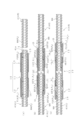
- FIG. 3 is a diagram showing the completion of fastening reinforcing bars using the coupler for threaded reinforcing bars according to the first invention.
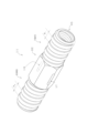
- FIG. 3 is a perspective view of the main cylinder.
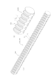
- FIG. 3 is an external perspective view of the sub-tube.
- the screw end view showing the meshing start point Q in the sub cylinder.
- Equal pitch setting process diagram using a gauge.
- the coupler 10 into which the opposing ends of the two reinforcing bars 4L and 4R shown in FIG. 2(a) are inserted prevents loosening of the threaded connection with the reinforcing bars 4 and allows the reinforcing bars to transmit axial force to elongate.
- This coupler 10 includes one main cylinder 11 and secondary cylinders 12 and 13 arranged symmetrically, that is, for each reinforcing bar. Therefore, the coupler 10 is extremely simple and has little bulk, consisting of three components. All of the components are rigid bodies made of metal, but as will be discussed later, they are basically cast products.
- the main cylinder 11 has an outer diameter approximately 1.4 times larger than the reinforcing steel, and has the appearance shown in FIG. has a hexagonal surface), and external threads M6 and M7, which will be described later, are formed on the outer surfaces of the left half shell and right half shell.
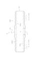
- the axial hole formed in the main cylinder 11 is a through screw hole that screws into the threaded joint M4 (see Fig. 5) of the reinforcing bars 4L and 4R, even if a meshing gap (including a back gap) remains. H5 (see Figure 4).
- this through-screw hole H5 is normally a right-handed thread in both the left half shell and the right half shell, but it is sufficient for meshing and joining with the screw threads M4 of reinforcing bars 4L and 4R to achieve the specified fastening performance.
- a suitable number of female screws F5 (for example, 5 to 6 as shown in FIG. 6) are provided.
- the pitch of the thread from one opening end to the other opening end of the through screw hole H5 is constant, and even if the spiral in the through screw hole H5 is interrupted (not shown) or not (not shown).
- the through-screw hole H5 is not interrupted even at the location of the peephole in part E of 6), and the screw phase is also the same in the left half shell and the right half shell.
- the threaded hole H5 is a reinforcing bar that allows the forming tolerance of the thread pitch in consideration of the wear of the forming roll
- the number of female threads F5 (see Fig. 6) that will achieve the necessary engagement for fastening will be sufficient.
- the female thread F5 of the through-screw hole H5 in the main cylinder 11 satisfies the meshing of the desired number of pitches, regardless of whether the reinforcing bar has the maximum allowable pitch or the minimum allowable pitch, and then The number of spirals is within the range that allows normal screwing without mutual interference.
- this main cylinder 11 needs to engage for example 5 to 6 pitches on the one hand, 12 pitches in total on the left and right sides, and Even if the reinforcing bar end butting space E (see Figure 6) is added, the coupler will have a total length of about 300 mm at most.
- the outer periphery of the left half shell and the outer periphery of the right half shell of the main cylinder 11 are provided with reinforcing bars that are concentric with the through screw hole H5 and have a phase that matches the phase of the through screw hole H5.
- the outer circumferential threads 6, 7 are formed with pitches P 6 and P 7 (see FIGS. 4 and 6) that are not equal to the pitch P 4 (see FIG. 5) of the threaded joints M4 of No. 4.
- the reason for giving a difference of 2 mm is not only to cause squeaks, but also to absorb several pitches even if there is some accumulation of pitch forming tolerance of reinforcing bars (for example, ⁇ 0.2 mm). The intention is to keep it that way.
- the auxiliary cylinders 12 and 13 have an appearance as shown in FIG. 7, and include sleeve parts 8 and 9 that respectively cover the outer periphery of the left half cylinder (see FIG. 6) and the right half cylinder of the main cylinder 11.
- Nut parts 14 and 15 are provided which are coaxial with the sleeve part and integrally formed at one end of the sleeve part.
- sleeve inner circumferential screws F8 and F9 that engage with the above-mentioned outer circumferential screws 6 and 7 (see FIGS. 4 and 6) are provided, and the nut portion 14 and 15 have this sleeve inner circumference screw F8.
- Nut female threads F14 and F15 are formed to which threaded nodes M4 of the reinforcing bars are screwed together, and have a phase that matches that of F9.
- the thread pitches P 14 and P 15 are the same as the thread pitch P 4 in a molded product with minimum reinforcing bar tolerance (meaning a product that conforms to the standard dimensions in the manufacturing drawing). are being equalized.
- the number of threads that engage with the reinforcing bar 4 due to the female threads F14 and F15 of the nut part is the number of threads that engage with the reinforcing bar 4 to exert a fastening effect on the outer periphery of the left half shell and the outer periphery of the right half shell of the main cylinder 11. It will be done.
- the coupler 10 is formed with a through screw hole H5 and female screw threads F14 and F15 in the nut part, female screw thread F14 in the nut part, female screw F5 in the through screw hole H5, and female screw thread F5 in the nut part.
- a screw hole with a constant pitch P4 is formed by the female screw F15, and the ends of the left and right reinforcing bars 4L and 4R can be held therein.
- the female thread F5 of the through screw hole H5 As shown in FIG. 3(b), as a result, the female thread F5 of the through screw hole H5, the male threads M6 and M7 at the ends of the outer circumferential screws 6 and 7, the female threads F8 and F9 on the inner circumference of the sleeve, and the female threads F14 and F15 at the nut part.
- the phase of all screws is the same.
- the same phase means that the rotation angles of the screw ends are the same when the screws begin to engage. That is, the rotation referred to here refers to the rotation angle ⁇ in FIG. 9 at the time when the tip of the male screw is dropped into the opening of the female screw and when biting starts.
- the rotation angles at the start of engagement are the same, that is, the rotation angle positions at the start of engagement are the same, for example, the advancing angle from the point U (for example, 2 ⁇ /3 rad 120 degrees) means to start meshing all at once.
- a desired torque capable of maintaining the fastening strength is applied to the nut portions 14 and 15 (see FIG. 7), and the reaction torque applying surface 11C having a polygonal cross section (see FIG. 4) is applied.
- the nut part female threads F14 and F15 of the nut parts 14 and 15 come into close pressure contact with the screw M4 of the reinforcing bars 4L and 4R to exert a frictional force (Fig. 3 (c) (See ⁇ Squeak expression''). Thereby, unintended rotation or axial displacement of the reinforcing bars can be prevented.
- a slit 17 extending in the axial direction is formed through which the tip positions of the inserted reinforcing bars 4L and 4R can be viewed.
- a slit 18 of the same shape is formed in the main cylinder 11 at a location opposite to this slit, the abutting end of the reinforcing bar 4 can be easily grasped by seeing through it, and the insertion depth of the reinforcing bar can be prevented from being mistaken.
- outer circumferential screws 6 and 7 formed on the outer periphery of the left half shell and the outer periphery of the right half shell of the main cylinder 11 have a phase that matches the phase of the female thread F5 of the through screw hole H5.
- the internal threads of the sleeve F8 and F9 should be attached to the female threads F14 and F15 (see Fig. 7) of the nut part, which the threaded joint M4 of the reinforcing bar (see Fig. 5) screws into.
- Having a phase that matches that of is not easy to achieve with cutting (machining) operations.
- all tooth surfaces must be brought into initial engagement at the same time, but the process to achieve this must rely on casting. Since this is not directly related to the gist of the present invention, it will not be discussed here.
- a main cylinder 11 and two sub-cylinders 12, 13 are arranged at the connection site of the two threaded reinforcing bars 4L, 4R.
- the sub cylinders 12 and 13 may have the same specifications (same nominal diameter, pitch, phase, etc.), and are simply arranged symmetrically in posture.
- the sleeve inner circumferential screws F8 and F9 are engaged with the outer circumferential screws M6 and M7, and the sub-cylinder 12 is inserted deeply into one side of the main cylinder 11 so as to match the thread phase, and the other side is
- the sub-tube 13 is also screwed deeply into the side so that the screw phases match.
- the central barrel 11C has a square cross section (see Fig. 4), and the sub-tubes 12 and 13 have a shape and size that cannot cover that part, but most of the left half barrel and right half barrel. is covered. Although the sub cylinders 12 and 13 do not cover the slits 17 and 18, they are arranged close to each other.
- the threaded reinforcing bars 4R are brought closer to the threaded reinforcing bars 4L (see FIG. 2(c)).
- the tip 4Le of the threaded reinforcing bar 4L is projected by about one pitch as shown in FIG. Maintain continuity. In other words, phase misalignment is prevented.
- the entire coupler 10 is moved (rotated to the right) as shown in FIG. 3(b). Since the nut part female thread F14 of the sub cylinder 12, the female thread F5 of the through screw hole H5 of the main cylinder 11, and the nut part female thread F15 of the sub cylinder 13 are continuous, the movement operation to the threaded reinforcing bar 4L is not difficult. . That is, the opposite ends of the threaded reinforcing bars 4R and 4L are kept at a predetermined gap E (see FIG. 3(b)), and the coupler 10 is screwed toward the threaded reinforcing bars 4R.
- the sub cylinders 12 and 13 move to follow the outer circumferential screws 6 and 7, but the nut female screws F14 and F15 tend to move as if guided by the threaded reinforcing bars.
- the amount of movement guided by the outer circumferential screw 6 is one pitch P6 .
- the sub cylinders 12 and 13 also try to move along the outer circumferential screws 6 and 7, but when the sub cylinders 12 and 13 move, for example, one rotation along the male thread M4 of the reinforcing bar, the pitch P along the outer circumferential screw 6 This is because you will have to walk 6 +2mm.
- both the threaded reinforcing bars 4L and 4R may be moved in the axial direction, there is no need to rotate them for screwing and screwing. That is, the fastening can be achieved only by rotating the main cylinder 11 and the sub cylinders 12 and 13.
- the essential configuration for realizing the above operations is expressed as follows. Referring to FIG. The ends of opposing reinforcing bars 4L and 4R of the same specifications (same diameter, same pitch, same screw phase) are inserted into the coupler, and the reinforcing bars that transmit axial force are lengthened to prevent loosening of the reinforcing bars and couplers.
- a coupler that is fastened to keep the The coupler 10 includes one main cylinder 11 and two sub-cylinders 12 and 13 that are symmetrically arranged and screwed onto the outer peripheries of the left and right half cylinders of the main cylinder 11,
- the axial hole formed in the main cylinder 11 is a vertical screw hole H5 into which the threaded joints M4 of the reinforcing bars 4L and 4R are screwed,
- outer circumferential screws H6 and H7 are formed which are concentric with the vertical screw hole H5 and have a larger diameter than the vertical screw hole H5, and male end screws M6 and M7 are provided therein.
- the end male screws M6, M7 have a phase that matches the phase of the female screw F5 of the through screw hole H5, have pitches P6 , P7 different from the screw pitch P4 of the threaded joints M4 of the reinforcing bars 4L, 4R,
- the cylinders 12 and 13 have sleeve parts 8 and 9 with female threads F8 and F9 at the ends that are screwed into the male threads M6 and M7 at the ends, and a nut coaxial with the sleeve parts and integrally formed at one end of the sleeve part.
- the present invention is a lock that utilizes the squeak caused by the strong contact between the tooth surfaces of the screws.
- the configuration shown in FIG. 12, which is reversed, can also achieve the desired locking using the squeak.
- the coupler 10A includes one main cylinder 11A and two sub-cylinders 12A and 13A that are symmetrically arranged and screwed into the inner holes of the left and right half cylinders of the main cylinder,
- the axial hole formed in the main cylinder 11A is a vertical screw hole H5 into which the threaded node M4 of the reinforcing bar is screwed, End female screw holes H6 and H7 are formed in the inner holes of the left and right half bodies, and are concentric with the vertical screw hole H5 and have a larger diameter than the vertical screw hole H5.
- auxiliary cylinders 12A and 13A are coaxial with the sleeve parts 8A and 9A, which have male end screws M8 and M9 that are screwed into the female end screws F6 and F7, and are integrally formed at one end of the sleeve part.
- the nut parts 14A, 15A are formed with female threads F14, F15 of the nut part, which are screwed together with the threaded nodes M4 of the reinforcing bars 4L, 4R, and have a phase that matches that of the male end threads M8, M9. be.
- the reinforcing bars to be connected are each made of the same components and can be fastened using the same torque-loading process. If the reinforcing bars have threaded joints within the forming tolerance, even if there are variations in the pitch of the threaded joints, the reinforcing bars can be fastened uniformly. Since the outer circumferential threads (or end female threads) on the left and right half shell outer peripheries of the main cylinder and the threaded joints of the reinforcing bars have different pitches, the surface contact pressure of the threads increases. This increases the frictional force acting on the surface of the screw. When the surface of the screw thread becomes rough due to pressure, it prevents it from further advancing or retracting, and squeaks occur in the meshing areas where there is a difference in pitch, except for the normal meshing areas.
- An outer circumferential thread (or end female thread) with a pitch larger than the pitch of the threaded joints of the reinforcing bar is formed on the left half shell outer periphery and right half shell outer periphery of the main cylinder, or an outer circumferential thread (or end female thread) with a smaller pitch is formed.
- This difference in pitch makes it possible to identify the thread where the frictional force acting on the surface of the thread is large due to the surface contact pressure of the thread, and it is also easy to select the material for the main cylinder.
- a reaction force absorbing surface is formed on the outer surface of the through screw hole, which is the central portion in the longitudinal direction of the main cylinder, it becomes easy to perform a reaction force receiving operation when applying a desired torque to the polygonal nut portion.
- a slit extending in the axial direction is formed in the through-screw hole, which is the longitudinally intermediate portion of the main cylinder, the tip position of the inserted reinforcing bar can be confirmed. If a slit of the same shape is formed at a location opposite to this slit, it will be possible to see through the slit, making it easier to confirm the tip position of the inserted reinforcing bar.
- the reinforcing bar can also have a fixing function. Even if the fixing location is planned in advance, there is an advantage that it can be handled quickly if a change is required.
- the present invention does not intend to exclude the use of grout (mortar, adhesive, screw locking agent, etc.) in combination. In other words, this does not mean that grout or the like should not be introduced in the structure of the present invention, but rather that injection of grout is often unnecessary in principle, and that grouting is done in a known manner and used for locking. It goes without saying that it is okay to do so.
- grout memory, adhesive, screw locking agent, etc.
- Threaded joint reinforcing bar M4: Threaded joint: 4Le: Tip of threaded joint reinforcing bar, 6, 7; Outer periphery screw, H6, H7; End female screw hole, F6, F7; End female screw, M6 , M7; male end thread, 10, 10A; coupler, 11, 11A; main cylinder, 11C: center cylinder (reaction force taking surface), 12, 12A, 13, 13A; sub cylinder, H5: vertical threaded hole, F5: Female thread, 8, 8A, 9, 9A; Sleeve part, F8, F9: Sleeve inner circumference thread, M8, M9: Sleeve part male thread, 14, 14A, 15, 15A: Nut part, F14, F15: Nut female thread, 17, 18: slit, 19: gauge, 21, 22: arrow in the direction of departure, 23, 24: arrow in the direction of approach, 25: bent part, P 4 : thread joint in minimum tolerance molded product Pitch, P 6 , P 7 ; Thread pitch
Landscapes
- Engineering & Computer Science (AREA)
- Architecture (AREA)
- Civil Engineering (AREA)
- Structural Engineering (AREA)
- Reinforcement Elements For Buildings (AREA)
- Mutual Connection Of Rods And Tubes (AREA)
Abstract
Description
カプラー10は一つの主筒11と左右対称姿勢にあって主筒11の左半部胴および右半部胴の外周に螺着される二つの副筒12,13とを備え、
主筒11内に形成される軸方向の孔は、鉄筋4L,4Rのネジ節M4が螺合する縦通ネジ孔H5であり、
左右の半部胴の外周には縦通ネジ孔H5と同心でこの縦通ネジ孔H5より大径の外周ネジ6,7が形成され、そこには端部雄ネジM6,M7が設けられ、
端部雄ネジM6,M7は縦通ネジ孔H5の雌ネジF5の位相と一致する位相を備え、鉄筋4L,4Rのネジ節M4のネジピッチP4とは異なるピッチP6,P7を持ち、
副筒12,13は端部雄ネジM6,M7に螺着する端部雌ネジF8,F9を備えるスリーブ部8,9と、このスリーブ部と同軸をなしスリーブ部の片側端に一体形成されたナット部14,15とを備え、
ナット部14,15には鉄筋4L,4Rのネジ節M4が螺合し前記端部雌ネジF8,F9の位相と一致する位相を備えたナット部雌ネジF14,F15が形成されていることである。
対向する同一仕様(同一直径・同一ピッチ・同一ネジ位相)の鉄筋4L,4Rの端部が挿入されるカプラー内に鉄筋とカプラーとの緩みを防止して、軸力を伝達する鉄筋を長くしておくため締結するカプラーであって、
カプラー10は一つの主筒11と左右対称姿勢にあって主筒11の左半部胴および右半部胴の外周に螺着される二つの副筒12,13とを備え、
主筒11内に形成される軸方向の孔は、鉄筋4L,4Rのネジ節M4が螺合する縦通ネジ孔H5であり、
左右の半部胴の外周は縦通ネジ孔H5と同心でこの縦通ネジ孔H5より大径の外周ネジH6,H7が形成され、そこに端部雄ネジM6,M7が設けられ,
端部雄ネジM6,M7は貫通ネジ孔H5の雌ネジF5の位相と一致する位相を備え、鉄筋4L,4Rのネジ節M4のネジピッチP4とは異なるピッチP6,P7を持ち、副筒12,13は端部雄ネジM6,M7に螺着する端部雌ネジF8,F9を備えるスリーブ部8,9と、このスリーブ部と同軸をなしスリーブ部の片側端に一体形成されたナット部14,15とを備え、
ナット部14,15には鉄筋4L,4Rのネジ節M4が螺合しスリーブ部8,9の端部雌ネジF8,F9の位相と一致する位相を備えたナット部雌ネジF14,F15が形成されている。
対向する鉄筋4L,4Rの端部が挿入されるカプラー内に鉄筋とカプラーとの緩みを防止して、軸力を伝達する鉄筋を長くしておくため締結するカプラーにおいて、
カプラー10Aは一つの主筒11Aと左右対称姿勢にあって主筒の左半部胴および右半部胴の内孔に螺着される二つの副筒12A,13Aとを備え、
主筒11A内に形成される軸方向の孔は、鉄筋のネジ節M4が螺合する縦通ネジ孔H5であり、
左右の半部胴の内孔には縦通ネジ孔H5と同心で、この縦通ネジ孔H5より大径の端部雌ネジ孔H6,H7が形成され、そこには端部雌ネジF6,F7が設けられ、
この端部雌ネジF6,F7は貫通ネジ孔H5の雌ネジF5の位相と一致する位相を備え、鉄筋4L,4Rのネジ節M4のネジピッチP4とは異なるピッチP6,P7を持ち、
副筒12A,13Aは端部雌ネジF6,F7に螺着する端部雄ネジM8,M9を備えるスリーブ部8A,9Aと、このスリーブ部と同軸をなしスリーブ部の片側端に一体形成されたナット部14A,15Aとを備え、
このナット部14A,15Aには鉄筋4L,4Rのネジ節M4が螺合し端部雄ネジM8,M9の位相と一致する位相を備えたナット部雌ネジF14,F15が形成されていることである。
Claims (11)
- 対向する鉄筋の端部が挿入されるカプラー内に鉄筋とカプラーとの緩みを防止して、軸力を伝達する鉄筋を長くしておくため締結するカプラーにおいて、
前記カプラーは一つの主筒と左右対称姿勢にあって該主筒の左半部胴および右半部胴の外周に螺着される二つの副筒とを備え、
前記主筒内に形成される軸方向の孔は、前記鉄筋のネジ節が螺合する縦通ネジ孔であり、
左右の半部胴の前記外周には前記縦通ネジ孔と同心でこの縦通ネジ孔より大径の外周ねじが形成され、そこには端部雄ネジが設けられ、
該端部雄ネジは前記縦通ネジ孔の雌ネジの位相と一致する位相を備え、前記鉄筋のネジ節のネジピッチとは異なるピッチを持ち、
前記副筒は前記端部雄ネジに螺着する端部雌ネジを備えるスリーブ部と、該スリーブ部と同軸をなしスリーブ部の片側端に一体形成されたナット部とを備え、
該ナット部には前記鉄筋のネジ節が螺合し前記端部雌ネジの位相と一致する位相を備えたナット部雌ネジが形成されていることを特徴とするネジ節鉄筋用カプラー。 - 前記主筒の左半部胴外周および右半部胴外周には、前記鉄筋のネジ節のピッチより大きいピッチの外周ネジが形成されていることを特徴とする請求項1に記載されたネジ節鉄筋用カプラー。
- 前記主筒の左半部胴外周および右半部胴外周には、前記鉄筋のネジ節のピッチより小さいピッチの外周ネジが形成されていることを特徴とする請求項1に記載されたネジ節鉄筋用カプラー。
- 対向する鉄筋の端部が挿入されるカプラー内に鉄筋とカプラーとの緩みを防止して、軸力を伝達する鉄筋を長くしておくため締結するカプラーにおいて、
カプラーは一つの主筒と左右対称姿勢にあって主筒の左半部胴および右半部胴の内孔に螺着される二つの副筒とを備え、
前記主筒内に形成される軸方向の孔は、鉄筋のネジ節が螺合する縦通ネジ孔であり、
左右の半部胴の前記内孔には縦通ネジ孔と同心で、この縦通ネジ孔より大径の端部雌ネジ孔が形成され、そこには端部雌ネジが設けられ、
該端部雌ネジは前記貫通ネジ孔の雌ねじの位相と一致する位相を備え、鉄筋のネジ節のネジピッチとは異なるピッチを持ち、
前記副筒は端部雌ネジに螺着する端部雄ネジを備えるスリーブ部と、該スリーブ部と同軸をなしスリーブ部の片側端に一体形成されたナット部とを備え、
ナット部には前記鉄筋のネジ節が螺合し前記端部雄ネジの位相と一致する位相を備えたナット部雌ネジが形成されていることを特徴とするネジ節鉄筋用カプラー。 - 前記主筒の左半部胴内孔および右半部胴内孔には、前記鉄筋のネジ節のピッチより大きいピッチの端部雌ネジ孔が形成されていることを特徴とする請求項4に記載されたネジ節鉄筋用カプラー。
- 前記主筒の左半部胴内孔および右半部胴内孔には、前記鉄筋のネジ節のピッチより小さいピッチの端部雌ネジ孔が形成されていることを特徴とする請求項4に記載されたネジ節鉄筋用カプラー。
- 前記主筒の長手方向中央部位であるの中央胴の外面には、前記ナット部に所望トルクを及ぼす際の反力取り面が形成されていることを特徴とする請求項1または請求項4に記載されたネジ節鉄筋用カプラー。
- 前記主筒の長手方向中間部位であるの中央胴には、挿入鉄筋の先端位置を確認するため覗きうる軸方向に延びるスリットが形成されていることを特徴とする請求項1または請求項4に記載されたネジ節鉄筋用カプラー。
- 前記スリットの対向箇所にも同形のスリットが前記主筒に形成されていることを特徴とする請求項8に記載されたネジ節鉄筋用カプラー。
- 前記鉄筋の反カプラー側端部が定着板機能を発揮する曲がり部を有していることを特徴とする請求項1または請求項4に記載されたネジ節鉄筋用カプラー。
- 請求項1ないし請求項10のいずれか一項に記載のネジ節鉄筋用カプラーが具備されたことを特徴とするネジ節鉄筋。
Priority Applications (4)
| Application Number | Priority Date | Filing Date | Title |
|---|---|---|---|
| EP23803624.8A EP4524341A4 (en) | 2022-05-12 | 2023-05-12 | COUPLER FOR THREADED REBAR AND THREADED REBAR EQUIPPED WITH SAID COUPLER |
| US18/864,010 US12559944B2 (en) | 2022-05-12 | 2023-05-12 | Coupler for threaded reinforcing bar and threaded reinforcing bar including the coupler |
| CN202380038969.5A CN119173670A (zh) | 2022-05-12 | 2023-05-12 | 螺纹节钢筋用耦合器及具备该耦合器的螺纹节钢筋 |
| JP2024520493A JP7555691B2 (ja) | 2022-05-12 | 2023-05-12 | ネジ節鉄筋用カプラーおよびそのカプラーが具備されたネジ節鉄筋 |
Applications Claiming Priority (2)
| Application Number | Priority Date | Filing Date | Title |
|---|---|---|---|
| JP2022-078707 | 2022-05-12 | ||
| JP2022078707 | 2022-05-12 |
Publications (1)
| Publication Number | Publication Date |
|---|---|
| WO2023219150A1 true WO2023219150A1 (ja) | 2023-11-16 |
Family
ID=88730304
Family Applications (1)
| Application Number | Title | Priority Date | Filing Date |
|---|---|---|---|
| PCT/JP2023/017830 Ceased WO2023219150A1 (ja) | 2022-05-12 | 2023-05-12 | ネジ節鉄筋用カプラーおよびそのカプラーが具備されたネジ節鉄筋 |
Country Status (5)
| Country | Link |
|---|---|
| US (1) | US12559944B2 (ja) |
| EP (1) | EP4524341A4 (ja) |
| JP (1) | JP7555691B2 (ja) |
| CN (1) | CN119173670A (ja) |
| WO (1) | WO2023219150A1 (ja) |
Citations (7)
| Publication number | Priority date | Publication date | Assignee | Title |
|---|---|---|---|---|
| US4666326A (en) | 1982-09-11 | 1987-05-19 | Metal Bond (Technology) Limited | Reinforcing bar coupling system |
| US5046878A (en) | 1988-06-21 | 1991-09-10 | Metal-Bond (Technology) Limited | Reinforcing bar coupling system |
| US7107735B2 (en) | 2002-05-01 | 2006-09-19 | Ultimate Design Solutions Ltd. | Coupling device |
| JP2014005703A (ja) * | 2012-06-27 | 2014-01-16 | Tokai Corp | 異形鉄筋のねじ式鉄筋継手使用の接続構造および布基礎配筋構造 |
| JP2016532029A (ja) * | 2014-07-08 | 2016-10-13 | クァン キ,オン | 螺旋鉄筋用鉄筋連結具 |
| JP2018178365A (ja) | 2017-04-03 | 2018-11-15 | 株式会社安藤・間 | 鉄筋継手カプラー |
| KR20210075660A (ko) * | 2019-12-13 | 2021-06-23 | 송재혁 | 내진용 철근 커플러 |
Family Cites Families (9)
| Publication number | Priority date | Publication date | Assignee | Title |
|---|---|---|---|---|
| US1480253A (en) * | 1923-05-11 | 1924-01-08 | Daniel C Fisher | Turnbuckle |
| JPS56162721U (ja) | 1980-05-02 | 1981-12-03 | ||
| JPH11229557A (ja) | 1998-02-18 | 1999-08-24 | Tokyo Tekko Co Ltd | ねじ鉄筋用連結装置 |
| JP2003239458A (ja) | 2001-07-09 | 2003-08-27 | Nippon Steel Corp | ねじ節鉄筋用ねじ継手及びねじ節鉄筋用カプラーの製造方法 |
| KR200409526Y1 (ko) | 2005-11-23 | 2006-03-03 | 김용근 | 나사 마디 철근의 이음을 위한 나사형 슬리브 |
| KR20070054417A (ko) * | 2005-11-23 | 2007-05-29 | 김용근 | 나사 마디 철근의 이음을 위한 나사형 슬리브 |
| JP2008145703A (ja) | 2006-12-08 | 2008-06-26 | Canon Inc | 投射光学系及び画像投射装置 |
| KR101650946B1 (ko) * | 2014-10-02 | 2016-09-19 | 엘케이테크 주식회사 | 나선철근용 철근정착장치 |
| CN214461818U (zh) * | 2020-11-11 | 2021-10-22 | 徐瑞榕 | 一种钢筋机械连接接头 |
-
2023
- 2023-05-12 EP EP23803624.8A patent/EP4524341A4/en active Pending
- 2023-05-12 WO PCT/JP2023/017830 patent/WO2023219150A1/ja not_active Ceased
- 2023-05-12 US US18/864,010 patent/US12559944B2/en active Active
- 2023-05-12 CN CN202380038969.5A patent/CN119173670A/zh active Pending
- 2023-05-12 JP JP2024520493A patent/JP7555691B2/ja active Active
Patent Citations (7)
| Publication number | Priority date | Publication date | Assignee | Title |
|---|---|---|---|---|
| US4666326A (en) | 1982-09-11 | 1987-05-19 | Metal Bond (Technology) Limited | Reinforcing bar coupling system |
| US5046878A (en) | 1988-06-21 | 1991-09-10 | Metal-Bond (Technology) Limited | Reinforcing bar coupling system |
| US7107735B2 (en) | 2002-05-01 | 2006-09-19 | Ultimate Design Solutions Ltd. | Coupling device |
| JP2014005703A (ja) * | 2012-06-27 | 2014-01-16 | Tokai Corp | 異形鉄筋のねじ式鉄筋継手使用の接続構造および布基礎配筋構造 |
| JP2016532029A (ja) * | 2014-07-08 | 2016-10-13 | クァン キ,オン | 螺旋鉄筋用鉄筋連結具 |
| JP2018178365A (ja) | 2017-04-03 | 2018-11-15 | 株式会社安藤・間 | 鉄筋継手カプラー |
| KR20210075660A (ko) * | 2019-12-13 | 2021-06-23 | 송재혁 | 내진용 철근 커플러 |
Non-Patent Citations (1)
| Title |
|---|
| See also references of EP4524341A4 |
Also Published As
| Publication number | Publication date |
|---|---|
| EP4524341A4 (en) | 2026-03-11 |
| JP7555691B2 (ja) | 2024-09-25 |
| CN119173670A (zh) | 2024-12-20 |
| EP4524341A1 (en) | 2025-03-19 |
| US20250327303A1 (en) | 2025-10-23 |
| US12559944B2 (en) | 2026-02-24 |
| JPWO2023219150A1 (ja) | 2023-11-16 |
Similar Documents
| Publication | Publication Date | Title |
|---|---|---|
| KR101456825B1 (ko) | 로킹편 쌍이 구비된 철근연결구 및 이를 이용한 선조립 철근망의 연결이음 공법 | |
| US20190177976A1 (en) | Screw-type rebar joint structure of deformed rebar and manufacturing method thereof | |
| EP3141672B1 (en) | Reinforcing bar coupler for spiral reinforcing bar | |
| KR101573735B1 (ko) | 나사형철근용 커플러 | |
| GB2495075A (en) | Coupling assembly and method for coupling reinforcing bars used in concrete blocks in an end to end relationship | |
| CN113202232A (zh) | 一种钢筋机械连接及安装方法 | |
| WO2023219150A1 (ja) | ネジ節鉄筋用カプラーおよびそのカプラーが具備されたネジ節鉄筋 | |
| JP6545735B2 (ja) | 異形棒鋼の製造方法およびアンカーボルトの製造方法 | |
| US11454268B2 (en) | Coupler for threaded reinforcing bar | |
| AU2020200495A1 (en) | Coupler for threaded reinforcing bar | |
| JPH11229557A (ja) | ねじ鉄筋用連結装置 | |
| JP7787139B2 (ja) | ネジ節鉄筋を利用した異形鉄筋用カプラー | |
| CN212295349U (zh) | 一种装配式预制构件钢筋直螺纹连接装置 | |
| CN120139431A (zh) | 一种用于钢筋模块化施工的钢筋机械连接装置及施工方法 | |
| US12253106B2 (en) | Coupler for threaded reinforcing bar | |
| JP2732354B2 (ja) | 摩擦圧接を用いた異形鉄筋のねじ式機械継手 | |
| KR20210075660A (ko) | 내진용 철근 커플러 | |
| KR102326335B1 (ko) | 이음길이 조절형 철근 커플러 및 이를 이용한 철근이음 시공방법 | |
| TWI787516B (zh) | 活用外螺紋部之不完整螺紋部的接頭 | |
| KR101132681B1 (ko) | 철근 연결구 | |
| JP3012301U (ja) | 不動状態にある二本の異形鉄筋の中間異形鉄筋を介した接続構造 | |
| JP4864619B2 (ja) | ねじ鉄筋の接続方法 | |
| JP6655672B2 (ja) | 雄ねじ部の不完全ねじ部を活用した継手 | |
| JPH045606Y2 (ja) | ||
| JP7606745B2 (ja) | ネジ鉄筋のピッチ合わせ装置 |
Legal Events
| Date | Code | Title | Description |
|---|---|---|---|
| 121 | Ep: the epo has been informed by wipo that ep was designated in this application |
Ref document number: 23803624 Country of ref document: EP Kind code of ref document: A1 |
|
| ENP | Entry into the national phase |
Ref document number: 2024520493 Country of ref document: JP Kind code of ref document: A |
|
| WWE | Wipo information: entry into national phase |
Ref document number: 2023803624 Country of ref document: EP |
|
| NENP | Non-entry into the national phase |
Ref country code: DE |
|
| ENP | Entry into the national phase |
Ref document number: 2023803624 Country of ref document: EP Effective date: 20241212 |
|
| WWP | Wipo information: published in national office |
Ref document number: 18864010 Country of ref document: US |