WO2023228564A1 - Dispositif d'aide à la découpe d'image, dispositif de diagnostic ultrasonore et procédé d'aide à la découpe d'image - Google Patents
Dispositif d'aide à la découpe d'image, dispositif de diagnostic ultrasonore et procédé d'aide à la découpe d'image Download PDFInfo
- Publication number
- WO2023228564A1 WO2023228564A1 PCT/JP2023/013111 JP2023013111W WO2023228564A1 WO 2023228564 A1 WO2023228564 A1 WO 2023228564A1 JP 2023013111 W JP2023013111 W JP 2023013111W WO 2023228564 A1 WO2023228564 A1 WO 2023228564A1
- Authority
- WO
- WIPO (PCT)
- Prior art keywords
- image
- video data
- images
- user
- support device
- Prior art date
- Legal status (The legal status is an assumption and is not a legal conclusion. Google has not performed a legal analysis and makes no representation as to the accuracy of the status listed.)
- Ceased
Links
Images


Classifications
-
- G—PHYSICS
- G16—INFORMATION AND COMMUNICATION TECHNOLOGY [ICT] SPECIALLY ADAPTED FOR SPECIFIC APPLICATION FIELDS
- G16H—HEALTHCARE INFORMATICS, i.e. INFORMATION AND COMMUNICATION TECHNOLOGY [ICT] SPECIALLY ADAPTED FOR THE HANDLING OR PROCESSING OF MEDICAL OR HEALTHCARE DATA
- G16H30/00—ICT specially adapted for the handling or processing of medical images
- G16H30/20—ICT specially adapted for the handling or processing of medical images for handling medical images, e.g. DICOM, HL7 or PACS
-
- A—HUMAN NECESSITIES
- A61—MEDICAL OR VETERINARY SCIENCE; HYGIENE
- A61B—DIAGNOSIS; SURGERY; IDENTIFICATION
- A61B8/00—Diagnosis using ultrasonic, sonic or infrasonic waves
- A61B8/13—Tomography
- A61B8/14—Echo-tomography
-
- G—PHYSICS
- G06—COMPUTING OR CALCULATING; COUNTING
- G06T—IMAGE DATA PROCESSING OR GENERATION, IN GENERAL
- G06T7/00—Image analysis
- G06T7/0002—Inspection of images, e.g. flaw detection
- G06T7/0012—Biomedical image inspection
-
- G—PHYSICS
- G06—COMPUTING OR CALCULATING; COUNTING
- G06T—IMAGE DATA PROCESSING OR GENERATION, IN GENERAL
- G06T2207/00—Indexing scheme for image analysis or image enhancement
- G06T2207/10—Image acquisition modality
- G06T2207/10132—Ultrasound image
-
- G—PHYSICS
- G06—COMPUTING OR CALCULATING; COUNTING
- G06T—IMAGE DATA PROCESSING OR GENERATION, IN GENERAL
- G06T2207/00—Indexing scheme for image analysis or image enhancement
- G06T2207/30—Subject of image; Context of image processing
- G06T2207/30004—Biomedical image processing
Definitions
- the present invention relates to an image extraction support device, an ultrasonic diagnostic apparatus, and an image extraction method used to extract images from video data.
- diagnostic devices such as so-called ultrasound diagnostic devices that capture images representing tomographic images of a subject inside a subject have been known.
- moving image data representing a tomographic image of a subject may be obtained by continuously acquiring a plurality of frames of images representing a tomographic image of the subject.
- Users such as doctors often diagnose a subject by checking video data acquired by a diagnostic device. Diagnosis results obtained in this way are often written in a report for recording or shared with users such as other doctors for treatment of a subject.
- Patent Document 1 detects the movement of an anatomical structure included in a group of images including one frame image specified by a user among multiple frames of images constituting video data, It is disclosed that a high-quality image is obtained by averaging a group of images in consideration of the detection results.
- Patent Document 1 it was necessary for the user to manually select one frame image from among a plurality of frames of images forming the video data. At this time, especially when trying to obtain higher quality images, the user needs to check multiple frames of images that make up the video data and then select a single frame image that best represents the findings of the subject. was there. This work is usually complicated and requires a lot of effort from the user.
- the present invention has been made to solve these conventional problems, and provides an image cutting support device, an ultrasonic diagnostic device, and an image cutting support method that allow a user to easily select an image from video data.
- the purpose is to
- An image extraction support device for extracting a typical image of a user's diagnosis target from video data comprising: a video data input section for inputting video data; a screening unit that selects a group of candidate images related to the typical image from the video data by image analysis of the video data; An image cutting support device comprising: a recommendation section that gives priority to each image of a candidate image group based on at least one of image analysis by a screening section and user information.
- the screening unit extracts images from video data every predetermined number of frames.
- Ultrasonic probe and an image generation unit that generates video data by transmitting and receiving ultrasound beams to and from the subject using an ultrasound probe;
- An image extraction support device according to claim 1, An ultrasound diagnostic apparatus in which video data generated by an image generation section is input to a video data input section.
- An image extraction support method for extracting a typical image of a user's diagnosis target from video data the method comprising: Enter the video data and By analyzing the video data, we select a group of candidate images related to typical images from the video data, An image extraction support method that prioritizes each image of a candidate image group based on at least one of image analysis and user information.
- the image cutting support device is an image cutting support device for cutting out a typical image of a user's diagnosis target from video data, and includes a video data input section for inputting video data; a screening unit that selects a group of candidate images related to the typical image from the video data by image analysis; and a screening unit that prioritizes each image of the candidate image group based on at least one of the image analysis by the screening unit and user information.
- FIG. 1 is a block diagram showing the configuration of an image cutout support device according to Embodiment 1 of the present invention.
- FIG. FIG. 3 is a diagram schematically showing a display example of a candidate image group. 3 is a flowchart showing the operation of the image cutting support device according to Embodiment 1 of the present invention.
- FIG. 2 is a block diagram showing the configuration of an ultrasonic diagnostic apparatus in Embodiment 2 of the present invention.
- FIG. 2 is a block diagram showing the configuration of a transmitting/receiving circuit in Embodiment 2 of the present invention.
- FIG. 2 is a block diagram showing the configuration of an image generation section in Embodiment 2 of the present invention.
- FIG. 3 is a block diagram showing the configuration of an image cutout support device according to Embodiment 3 of the present invention.
- FIG. 1 shows the configuration of an image cutout support device according to Embodiment 1 of the present invention.
- the image extraction support device is a device (not shown) that handles images or videos, such as a so-called ultrasound diagnostic device or an endoscope device, or a device that handles a series of images, such as a computed tomography (CT) device. It is connected to an external device, from which video data M representing a tomographic image inside the subject and constituted by a plurality of consecutive frames of images is taken in.
- a diagnostic device such as an ultrasound diagnostic device, an endoscope device, or a computed tomography device
- a so-called ultrasound probe for example, can also be connected to the image extraction support device.
- a recording medium in which the moving image data M is stored can also be connected to the image cutting support device.
- the image cutting support device has a video data input unit 11 that is connected to an external device (not shown) and inputs video data M from the external device.
- a screening section 12, a recommendation section 13, a display control section 14, and a monitor 15 are sequentially connected to the video data input section 11.
- an image memory 16 is connected to the recommendation section 13.
- a device control section 17 is connected to the video data input section 11, the screening section 12, the recommendation section 13, the display control section 14, and the image memory 16.
- an input device 18 is connected to the device control section 17 .
- users such as doctors report images that well represent the anatomical structure of a subject or findings of a disease, etc., in other words, images that can relatively easily determine the anatomical structure of a subject or findings of a disease, etc. may be used to create or share information with other users.
- the image extraction support device allows a user to select and crop an image that best represents the anatomical structure of a subject or findings such as a disease from a plurality of frames of images that constitute video data M. This is a device that provides support during emergency situations.
- the video data input section 11, the screening section 12, the recommendation section 13, the display control section 14, and the device control section 17 constitute a processor 19 for the image cutting support device.
- the video data input unit 11 inputs video data M from an external device (not shown) or the like.
- the video data input unit 11 includes, for example, a connection terminal for wired connection to an external device such as a diagnostic device or a recording medium via a communication cable (not shown), or an antenna for wireless connection to an external device. include.
- Examples of recording media connected to the video data input unit 11 include flash memory, HDD (Hard Disk Drive), SSD (Solid State Drive), FD (Flexible Disk), MO Disc (Magneto-Optical disk), MT (Magnetic Tape), RAM (Random Access Memory), CD (Compact Disc), DVD (Digital Versatile Disc) ), an SD card (Secure Digital card), or a USB memory (Universal Serial Bus memory).
- the screening unit 12 performs image analysis on the video data M input to the video data input unit 11 to select a group of candidate images related to typical images from a plurality of frame images that make up the video data M.
- a typical image is an image in which a user's diagnosis target, for example, an anatomical structure or a finding of a disease within a subject to be diagnosed is captured.
- candidate images related to typical images are images that are selected by the user as images that represent typical images well, that is, images that allow users such as doctors to easily determine findings of anatomical structures or diseases to be diagnosed. refers to a group of images that are candidates for
- the screening unit 12 can select a group of candidate images by extracting images from the video data M every predetermined number of frames.
- the time interval when a plurality of consecutive frames of images representing the anatomical structure of a subject are captured is often very short. Therefore, images of multiple frames captured within a certain period of time are often similar to each other.
- the screening unit 12 extracts images from the video data M every predetermined number of frames and selects a group of candidate images, thereby excluding images that are similar to each other from being selected, and selecting images that have a low degree of similarity to each other as candidate images. Can be sorted as a group.
- the screening unit 12 performs a process of calculating the similarity of any one frame image among the multiple frames of images constituting the video data M, or calculates the mutual similarity of multiple frames of images. Similar images located in neighboring frames are selected by performing general processing such as histogram comparison, normalized cross-correlation processing, feature point matching, and comparison of image embedding vectors using arbitrary learning models. It can also be excluded. Thereby, the screening unit 12 can select images with low similarity to each other as a candidate image group. Note that images of neighboring frames refer to images of multiple frames captured within the same time range.
- the screening unit 12 performs so-called histogram analysis on multiple frames of images constituting the video data M to identify images in the airborne radiation state, and converts the identified images in the airborne radiation state into candidate images. It can be excluded from group selection.
- the screening unit 12 has a predetermined threshold value regarding the image quality, and performs processing such as so-called edge detection on the multiple frames of images constituting the video data M.
- the image quality of the image can be calculated, and images having image quality equal to or lower than a threshold value can be selected as candidate images.
- the image quality described here refers to an index representing the sharpness of the edges of the anatomical structure of the subject in the image.
- the recommendation unit 13 gives priority to each image of the candidate image group selected by the screening unit 12, based on the image analysis by the screening unit 12, user information, etc.
- the user information includes, for example, the type of medical department to which the user who is a doctor belongs, the type of anatomical structure selected by the user in the past, and the like.
- the user's information can be entered in advance via the input device 18, for example.
- the recommendation unit 13 can perform organ determination on each image of the candidate image group and give a high priority to images in which organs are photographed.
- the recommendation unit 13 has, for example, template data representing typical shapes etc. of each of a plurality of organs of the subject, and compares the anatomical structure shown in the image with the plurality of template data.
- Organ determination can be performed using a template matching method.
- the recommendation unit 13 uses, for example, ResNet (Residual Neural Network), DenseNet (Dense Convolutional Network), AlexNet, Baseline, Batch Normalization, dropout regularization, NetWidth search, or NetDepth search. It is also possible to have a learning model that has learned the shape of an organ in an image using a model according to an algorithm such as the above, and to perform organ determination by inputting an image to the learning model.
- ResNet Residual Neural Network
- DenseNet DenseNet (Dense Convolutional Network)
- AlexNet Baseline
- Batch Normalization Dropout regularization
- NetWidth search NetDepth search
- the recommendation unit 13 can also take into account the user's information and give a high priority to images in which the organ determined by the organ determination and the user's information are related. For example, based on the user's information that the user is a doctor and belongs to the urology department, an image showing an organ such as a bladder that is related to the urology department among the candidate images selected by the screening unit 12 may be selected. can be given high priority.
- the recommendation unit 13 can also give a high priority to images that reflect the user's preferences based on the user's information. For example, the recommendation unit 13 identifies the user based on an ID (Identifier) or the like input by the user via the input device 18, and provides user information indicating the types of organs shown in images selected by the same user in the past. By referring to , it is possible to give a high priority to images that include the organ.
- ID Identifier
- the recommendation unit 13 has a threshold determined based on the number of times the same user has selected an image in which the same organ is shown in the past, and the recommendation unit 13 has a threshold value determined based on the number of times the same user has selected an image in which the same organ is shown in the past, and the recommendation unit 13 has a threshold value determined based on the number of times the same user has selected an image in which the same organ is shown in the past, and the recommendation unit 13 has a threshold value determined based on the number of times the same user has selected an image in which the same organ is shown in the past. It is also possible to give high priority to images.
- the recommendation unit 13 can also give a high priority to an image in which the organ determined by the organ determination and the information of the diagnostic device that captured the video data M are related. For example, if the diagnostic device that captured the video data M is used in the urology department, and the video data M that was captured is accompanied by information that the diagnostic device is used in the urology department. Based on the information that the diagnostic device is used in the urology department, the recommendation unit 13 selects images that show organs such as the bladder that are related to the urology department from among the candidate images selected by the screening unit 12. can be given high priority.
- the device information is linked to a plurality of frames of images forming the video data M, for example, according to a standard such as so-called DICOM (Digital Imaging and Communications in Medicine).
- the recommendation unit 13 determines the presence or absence of organs in the image, the relevance between the organs determined by organ determination and the user's information, the user's preferences, the relevance between the organs determined by organ determination and the information of the diagnostic device, etc. Images can be prioritized based on at least one of a plurality of conditions.
- the recommendation unit 13 uses an algorithm called so-called emphasis filtering to determine the presence or absence of organs in the image, the relationship between the organs determined by the organ determination and the user's information, the user's preferences, and the information determined by the organ determination. It is also possible to give priority to images by taking into account a plurality of conditions, such as the relationship between organs and information on diagnostic equipment.
- the device control unit 17 controls each part of the image cutting support device according to a pre-recorded program or the like.
- the device control unit 17 also monitors the images prioritized by the recommendation unit 13 and the images of multiple frames constituting the video data M input to the video data input unit 11, for example, as shown in FIG. It can be displayed on 15.
- a first display area R1 displays "Video”
- a second display area R2 displays "Candidate image list”
- a third display area displays "Detailed selection”.
- R3 is displayed.
- the first display area R1 shows the presence or absence of organs in the image, the relationship between the organs determined by organ determination and the user's information, the user's preferences, and the relationship between the organs determined by organ determination and the information of the diagnostic device.
- the condition selection buttons B1 to B4 which are used to select multiple conditions such as A search button B5 for selecting an image given a higher priority than the value, and a so-called slide bar SB1 for displaying each image of the candidate image group are displayed.
- a plurality of markers N are displayed on the slide bar SB1 to highlight and represent the positions on the time axis of the images of the plurality of frames selected by selecting the search button B5.
- the image U1 corresponding to the position on the slide bar SB1 is displayed. Further, for example, when one of the plurality of markers N is selected, the image U1 corresponding to that marker N is displayed.
- a display window W1 containing the reduced image U2 can be displayed.
- the user can easily grasp and select an image that best represents the anatomical structure or findings of the subject from the candidate image group.
- a plurality of images U3 that have been given a high priority by the recommendation unit 13 and have been reduced in size, and a slide bar SB2 are displayed in the second display area R2.
- the user can view the plurality of images U3 while sliding them up and down by operating the slide bar SB2.
- the user can also easily grasp an image that well represents the anatomical structure or findings of the subject by checking the second display area R2.
- a slide bar SB3 for the user to view multiple frames of images constituting the video data M, an image U4 corresponding to the operating position of the slide bar SB3, and a displayed image U4 are displayed in a report.
- a selection button B6 is displayed for selecting an image to be used for creating an image or sharing it with other users. The user can manually select an image using the third display area R3.
- FIG. 2 shows an example in which images U1 to U4 are ultrasound images.
- the image memory 16 stores images given high priority by the recommendation unit 13.
- a user such as a doctor can easily select from at least one frame of images stored in the image memory 16 an image to be used for creating a report or sharing with other users.
- a recording medium such as a flash memory, HDD, SSD, FD, MO disk, MT, RAM, CD, DVD, SD card, or USB memory can be used.
- the display control unit 14 performs predetermined processing on images of a plurality of frames constituting the video data M and displays them on the monitor 15 under the control of the device control unit 17 .
- the monitor 15 performs various displays under the control of the device control section 17.
- the monitor 15 can include, for example, a display device such as an LCD (Liquid Crystal Display) or an organic EL display (Organic Electroluminescence Display).
- the input device 18 accepts input operations by the user and sends the input information to the device control unit 17.
- the input device 18 includes, for example, a keyboard, a mouse, a trackball, a touch pad, a touch panel, and other devices for the examiner to perform input operations.
- the processor 19 having the video data input section 11, the screening section 12, the recommendation section 13, the display control section 14, and the device control section 17 of the image extraction support device is a CPU (Central Processing Unit); It consists of control programs to perform various processes on the FPGA (Field Programmable Gate Array), DSP (Digital Signal Processor), and ASIC (Application Specific Integrated Circuit). It may be configured using a GPU (Graphics Processing Unit), a GPU (Graphics Processing Unit), or other IC (Integrated Circuit), or a combination of these.
- CPU Central Processing Unit
- FPGA Field Programmable Gate Array
- DSP Digital Signal Processor
- ASIC Application Specific Integrated Circuit
- video data input section 11, screening section 12, recommendation section 13, display control section 14, and device control section 17 of the processor 19 may be partially or entirely integrated into one CPU or the like. can.
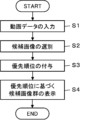
- step S1 video data M consisting of a plurality of continuous frames of images photographed inside the subject is inputted from an external device such as an ultrasound diagnostic apparatus (not shown) or a recording medium (not shown). The information is input to section 11.
- an ultrasound diagnostic apparatus not shown
- a recording medium not shown
- the screening unit 12 selects a group of candidate images related to typical images from the video data M by performing image analysis on the video data M input in step S1.
- the screening unit 12 can select a group of candidate images, for example, by extracting images from the video data M every predetermined number of frames.
- the time interval when taking continuous multiple frames of images representing the anatomical structure of a subject, such as so-called ultrasound images is very short, so multiple frames of images taken within a certain period of time are are often similar to each other. Therefore, by extracting images every predetermined number of frames from the video data M consisting of images of multiple consecutive frames, images that are similar to each other are excluded from selection, and images that have a low degree of similarity to each other are selected as candidate images. It can be selected as
- the recommendation unit 13 gives priority to each image of the candidate image group obtained in step S2, based on at least one of the image analysis by the screening unit 12 and the user's information.
- the recommendation unit 13 determines, for example, the presence or absence of organs in the image, the relationship between the organs determined by organ determination and the user's information, the user's preferences, and the relationship between the organs determined by organ determination and the information of the diagnostic device. Priorities can be given to images based on at least one of a plurality of conditions such as.
- the recommendation unit 13 uses an algorithm called emphasis filtering to determine the presence or absence of organs in the image, the relationship between the organs determined by the organ determination and the user's information, the user's preferences, and the organs determined by the organ determination. It is also possible to give priority to images by taking into account a plurality of conditions, such as the relationship between the image and the information on the diagnostic device.
- the recommendation unit 13 selects an image that well represents the anatomical structure of the subject or findings such as a disease. A high priority is given to images that are likely to be used when sharing diagnostic results of a subject with users.
- step S4 the device control unit 17 displays the candidate image group on the monitor 15 based on the priority given to the candidate image group in step S3.
- the recommendation unit 13 can display images U1 to U3 of the candidate image group as shown in FIG. Thereby, the user can easily grasp and select an image that well represents the anatomical structure of the subject or findings such as a disease.
- the device control unit 17 can display a plurality of frames of images U4 that constitute the video data M input in step S1.
- the user can also manually select an image from the multiple frames of images U4 that make up the video data M via the input device 18.
- step S4 When the process of step S4 is completed in this way, the operation of the image cutout support device according to the flowchart of FIG. 3 is completed.
- the screening unit 12 performs image analysis on the video data M to select a group of candidate images related to typical images from the video data M.
- the recommendation unit 13 gives priority to each of the candidate image groups based on at least one of the image analysis by the screening unit 12 and the user's information. You can easily understand and select an image that best represents the image.
- a user can set a plurality of conditions such as the relationship between the determined organ and the information of the diagnostic device via the input device 18. For example, if the condition selection buttons B1 to B4 shown in FIG. 2 are displayed on the monitor 15 in advance, the user can set a plurality of conditions using the condition selection buttons B1 to B4.
- step S4 when the recommendation unit 13 assigns a priority order to the images based on the user's input operation via the input device 18, It is also possible to change the conditions used. If a plurality of conditions are changed in this way, the process returns to step S3, and the recommendation unit 13 gives priority to the candidate image group again under the changed conditions.
- Embodiment 2 An ultrasonic diagnostic apparatus can also be formed by adding a configuration for acquiring ultrasonic images to the image extraction support apparatus of the first embodiment.
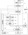
- the ultrasonic diagnostic apparatus includes an ultrasonic probe 2 and an apparatus main body 3 connected to the ultrasonic probe 2.
- the ultrasonic probe 2 can be connected to the device main body 3 by so-called wired communication or wireless communication.
- the ultrasonic probe 2 includes a transducer array 21 , and a transmitting/receiving circuit 22 is connected to the transducer array 21 .
- the device main body 3 includes an image generating section 31 connected to the transmitting/receiving circuit 22 of the ultrasound probe 2. Further, a display control section 32 and a monitor 33 are connected to the image generation section 31 in this order. Further, a video data input section 34, a screening section 35, and a recommendation section 36 are connected to the image generation section 31 in this order. Further, a display control section 32 and an image memory 38 are connected to the recommendation section 36 . Further, a main body control section 39 is connected to the transmission/reception circuit 22, the image generation section 31, the display control section 32, the video data input section 34, the screening section 35, and the recommendation section 36. Further, an input device 40 is connected to the main body control section 39 .
- the image generation section 31, display control section 32, video data input section 34, screening section 35, recommendation section 36, and main body control section 39 constitute a processor 41 for the device main body 3.
- the display control section 32, monitor 33, video data input section 34, screening section 35, recommendation section 36, image memory 38, main body control section 39, and input device 40 constitute an image cutout support device 42.
- the display control unit 32, monitor 33, video data input unit 34, screening unit 35, recommendation unit 36, image memory 38, and input device 40 are the same as the display control unit 14, monitor 15, video data input unit 34, and video data input unit 34 in the first embodiment.
- the unit 11, the screening unit 12, the recommendation unit 13, the image memory 16, and the input device 18 are the same. Therefore, a detailed description of the display control section 32, monitor 33, video data input section 34, screening section 35, recommendation section 36, image memory 38, and input device 40 will be omitted.
- the main body control section 39 is the same as the device control section 17 in the first embodiment, except for controlling the transmitting/receiving circuit 22 and the image generating section 31.
- the transducer array 21 of the ultrasound probe 2 has a plurality of ultrasound transducers arranged one-dimensionally or two-dimensionally. These ultrasonic transducers each transmit ultrasonic waves according to drive signals supplied from the transmitting/receiving circuit 22, receive ultrasonic echoes from the subject, and output signals based on the ultrasonic echoes.
- Each ultrasonic transducer is made of, for example, a piezoelectric ceramic represented by PZT (Lead Zirconate Titanate), a polymer piezoelectric element represented by PVDF (Poly Vinylidene Di Fluoride), and a PMN- It is constructed by forming electrodes at both ends of a piezoelectric material made of a piezoelectric single crystal, typified by PT (Lead Magnesium Niobate-Lead Titanate).
- PZT Lead Zirconate Titanate
- PVDF Poly Vinylidene Di Fluoride
- PMN- It is constructed by forming electrodes at both ends of a piezoelectric material made of a piezoelectric single crystal, typified by PT (Lead Magnesium Niobate-Lead Titanate).
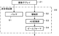
- the transmitting/receiving circuit 22 transmits ultrasonic waves from the transducer array 21 and generates a sound ray signal based on the received signal acquired by the transducer array 21 under the control of the main body control section 39 .
- the transmitter/receiver circuit 22 includes a pulser 51 connected to the transducer array 21, an amplifier section 52, an AD (Analog to Digital) converter 53, and a beam connected in series from the transducer array 21. It has a former 64.
- the pulser 51 includes, for example, a plurality of pulse generators, and transmits data from the plurality of ultrasonic transducers of the transducer array 21 based on a transmission delay pattern selected according to a control signal from the main body control section 39.
- Each driving signal is supplied to the plurality of ultrasonic transducers while adjusting the amount of delay so that the ultrasonic waves generated form an ultrasonic beam.
- a pulsed or continuous wave voltage is applied to the electrodes of the ultrasonic transducers of the transducer array 21, the piezoelectric material expands and contracts, and each ultrasonic transducer generates pulsed or continuous wave ultrasonic waves. is generated, and an ultrasonic beam is formed from the composite wave of those ultrasonic waves.
- the transmitted ultrasound beam is reflected at a target, such as a part of the subject, and propagates toward the transducer array 21 of the ultrasound probe 2.
- the ultrasonic echoes propagating toward the transducer array 21 in this manner are received by the respective ultrasonic transducers constituting the transducer array 21.
- each of the ultrasonic transducers constituting the transducer array 21 expands and contracts by receiving the propagating ultrasonic echoes, generates received signals that are electrical signals, and sends these received signals to the amplification section. 52.
- the amplifying section 52 amplifies the signals input from each of the ultrasonic transducers forming the transducer array 21 and transmits the amplified signals to the AD converting section 53.
- the AD converter 53 converts the signal transmitted from the amplifier 52 into digital received data.
- the beamformer 54 performs so-called reception focus processing by adding respective delays to each reception data received from the AD conversion unit 53. Through this reception focus processing, each reception data converted by the AD converter 53 is phased and added, and a sound ray signal in which the ultrasonic echo is focused is acquired.
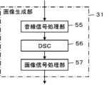
- the image generation section 31 has a configuration in which a sound ray signal processing section 55, a DSC (Digital Scan Converter) 56, and an image signal processing section 57 are connected in series. .
- the sound ray signal processing section 55 corrects the attenuation due to distance on the sound ray signal received from the transmitting/receiving circuit 22 according to the depth of the reflection position of the ultrasonic wave using the sound velocity value set by the main body control section 39. After that, envelope detection processing is performed to generate a B-mode image signal, which is tomographic image information regarding the tissue inside the subject.
- the DSC 56 converts (raster converts) the B-mode image signal generated by the sound ray signal processing section 55 into an image signal according to a normal television signal scanning method.
- the image signal processing section 57 generates an ultrasound image by performing various necessary image processing such as gradation processing on the B-mode image signal inputted from the DSC 56, and displays the generated ultrasound image on the display control section 32. and sends it to the video data input section 34.
- the ultrasound image sent to the display control section 32 is displayed on the monitor 33 via the display control section 32.
- the video data input unit 34 receives a plurality of consecutive frames of ultrasound images generated by the image generation unit 31 as video data M.
- the screening unit 35 performs image analysis on the video data M input by the video data input unit 34 to select candidate images related to typical images from the video data M.
- the recommendation unit 36 gives priority to each image of the candidate image group based on at least one of the image analysis by the screening unit 35 and the user's information.
- the screening unit 35 selects a group of candidate images related to typical images from the video data M by performing image analysis on the video data M, Since the recommendation unit 36 gives priority to each candidate image group based on at least one of the image analysis by the screening unit 35 and the user's information, the user can, as in the image cutting support device of the first embodiment, Images that well represent the anatomical structure of the subject or findings such as diseases can be easily grasped and selected.
- the ultrasonic probe 2 includes the transmitting/receiving circuit 22
- the device main body 3 may include the transmitting/receiving circuit 22 instead of the ultrasonic probe 2.
- the apparatus main body 3 includes the image generating section 31, the ultrasound probe 2 can also include the image generating section 31 instead of the apparatus main body 3.
- Embodiment 3 Image processing including adjustment of brightness, saturation, hue, etc. can also be performed so that the anatomical structure of the subject reflected in the image included in the video data M can be clearly seen.
- FIG. 7 shows the configuration of an image extraction support device according to Embodiment 3.
- the image cutting support device according to the third embodiment is the same as the image cutting support device according to the first embodiment except that an image processing section 61 is added and a device control section 17A is provided in place of the device control section 17.
- the video data input section 11, the screening section 12, the recommendation section 13, the display control section 14, the device control section 17A, and the image processing section 61 constitute a processor 19A for the image cutout support device of the third embodiment.
- the image processing unit 61 performs various image processing, such as brightness adjustment, saturation adjustment, hue adjustment, and noise reduction processing, on the images included in the video data M according to instructions from the user via the input device 18. I do.
- the image processing unit 61 may perform image processing of content specified by the user on an image selected by the user via the input device 18 from among multiple frames of images forming the video data M. can.
- the user can obtain, for example, an even clearer image that better represents the anatomical structure of the subject or findings such as diseases, which have been given a higher priority by the recommendation unit 13.
- the clear images obtained in this manner are useful, for example, when posting them in a report regarding the diagnosis results of the subject, or when sharing the diagnosis results of the subject with users such as other doctors.
- the image processing unit 61 also refers to user information input through the input device 18, stores the contents of image processing performed in the past according to instructions from the same user, It is also possible to automatically perform image processing tailored to the user's preferences based on the content of the image. This saves the user the trouble of giving instructions regarding the content of image processing.
- the image processed by the image processing unit 61 is displayed on the monitor 15 via the display control unit 14, and is stored in the image memory 16 under the control of the device control unit 17A.
- the image processing unit 61 since the image processing unit 61 performs image processing on the images included in the video data M, it is possible to create an image in which the anatomical structure is more clearly depicted. Can be obtained.
- an image processing section 61 can also be added to the ultrasound diagnostic apparatus in the second embodiment shown in FIG.
- the image processing unit 61 can perform image processing on multiple frames of ultrasound images successively generated by the image generation unit 31. Thereby, in the same way as the image extraction support device of Embodiment 3, it is possible to obtain an ultrasound image in which the anatomical structure is more clearly depicted.
Landscapes
- Engineering & Computer Science (AREA)
- Health & Medical Sciences (AREA)
- General Health & Medical Sciences (AREA)
- Medical Informatics (AREA)
- Nuclear Medicine, Radiotherapy & Molecular Imaging (AREA)
- Radiology & Medical Imaging (AREA)
- Public Health (AREA)
- Physics & Mathematics (AREA)
- Life Sciences & Earth Sciences (AREA)
- Primary Health Care (AREA)
- Theoretical Computer Science (AREA)
- Epidemiology (AREA)
- General Physics & Mathematics (AREA)
- Computer Vision & Pattern Recognition (AREA)
- Quality & Reliability (AREA)
- Pathology (AREA)
- Biophysics (AREA)
- Biomedical Technology (AREA)
- Heart & Thoracic Surgery (AREA)
- Molecular Biology (AREA)
- Surgery (AREA)
- Animal Behavior & Ethology (AREA)
- Veterinary Medicine (AREA)
- Ultra Sonic Daignosis Equipment (AREA)
Abstract
L'invention concerne un dispositif d'aide à la découpe d'image pour découper une image typique d'un emplacement à diagnostiquer chez un utilisateur à partir de données d'image mobile (M), le dispositif d'aide à la découpe d'image comprenant : une unité d'entrée de données d'image mobile (11) dans laquelle les données d'image mobile (M) sont entrées ; une unité de criblage (12) qui sélectionne un groupe d'images candidates relatif à une image typique à partir des données d'image mobile (M) en effectuant une analyse d'image des données d'image mobile (M) ; et une unité de recommandation (13) qui affecte un ordre de priorité à chacune des images dans le groupe d'images candidates sur la base de l'analyse d'image par l'unité de criblage (12) et/ou des informations d'utilisateur.
Priority Applications (2)
| Application Number | Priority Date | Filing Date | Title |
|---|---|---|---|
| JP2024522946A JPWO2023228564A1 (fr) | 2022-05-26 | 2023-03-30 | |
| US18/907,452 US20250029708A1 (en) | 2022-05-26 | 2024-10-04 | Image cutout support apparatus, ultrasound diagnostic apparatus, and image cutout support method |
Applications Claiming Priority (2)
| Application Number | Priority Date | Filing Date | Title |
|---|---|---|---|
| JP2022086182 | 2022-05-26 | ||
| JP2022-086182 | 2022-05-26 |
Related Child Applications (1)
| Application Number | Title | Priority Date | Filing Date |
|---|---|---|---|
| US18/907,452 Continuation US20250029708A1 (en) | 2022-05-26 | 2024-10-04 | Image cutout support apparatus, ultrasound diagnostic apparatus, and image cutout support method |
Publications (1)
| Publication Number | Publication Date |
|---|---|
| WO2023228564A1 true WO2023228564A1 (fr) | 2023-11-30 |
Family
ID=88918984
Family Applications (1)
| Application Number | Title | Priority Date | Filing Date |
|---|---|---|---|
| PCT/JP2023/013111 Ceased WO2023228564A1 (fr) | 2022-05-26 | 2023-03-30 | Dispositif d'aide à la découpe d'image, dispositif de diagnostic ultrasonore et procédé d'aide à la découpe d'image |
Country Status (3)
| Country | Link |
|---|---|
| US (1) | US20250029708A1 (fr) |
| JP (1) | JPWO2023228564A1 (fr) |
| WO (1) | WO2023228564A1 (fr) |
Citations (4)
| Publication number | Priority date | Publication date | Assignee | Title |
|---|---|---|---|---|
| JP2003299645A (ja) * | 2002-04-08 | 2003-10-21 | Hitachi Medical Corp | 画像診断支援装置 |
| JP2015173827A (ja) * | 2014-03-14 | 2015-10-05 | オリンパス株式会社 | 画像処理装置、画像処理方法、及び画像処理プログラム |
| US20160183923A1 (en) * | 2014-12-29 | 2016-06-30 | Samsung Medison Co., Ltd. | Ultrasonic imaging apparatus and method of processing ultrasound image |
| JP2019212138A (ja) * | 2018-06-07 | 2019-12-12 | コニカミノルタ株式会社 | 画像処理装置、画像処理方法及びプログラム |
-
2023
- 2023-03-30 JP JP2024522946A patent/JPWO2023228564A1/ja active Pending
- 2023-03-30 WO PCT/JP2023/013111 patent/WO2023228564A1/fr not_active Ceased
-
2024
- 2024-10-04 US US18/907,452 patent/US20250029708A1/en active Pending
Patent Citations (4)
| Publication number | Priority date | Publication date | Assignee | Title |
|---|---|---|---|---|
| JP2003299645A (ja) * | 2002-04-08 | 2003-10-21 | Hitachi Medical Corp | 画像診断支援装置 |
| JP2015173827A (ja) * | 2014-03-14 | 2015-10-05 | オリンパス株式会社 | 画像処理装置、画像処理方法、及び画像処理プログラム |
| US20160183923A1 (en) * | 2014-12-29 | 2016-06-30 | Samsung Medison Co., Ltd. | Ultrasonic imaging apparatus and method of processing ultrasound image |
| JP2019212138A (ja) * | 2018-06-07 | 2019-12-12 | コニカミノルタ株式会社 | 画像処理装置、画像処理方法及びプログラム |
Also Published As
| Publication number | Publication date |
|---|---|
| JPWO2023228564A1 (fr) | 2023-11-30 |
| US20250029708A1 (en) | 2025-01-23 |
Similar Documents
| Publication | Publication Date | Title |
|---|---|---|
| US10743841B2 (en) | Method of displaying elastography image and ultrasound diagnosis apparatus performing the method | |
| WO2020075609A1 (fr) | Dispositif et procédé de commande pour dispositif de diagnostic ultrasonore | |
| JPWO2017033502A1 (ja) | 超音波診断装置および超音波診断装置の制御方法 | |
| JP7719261B2 (ja) | 超音波システムおよび超音波システムの制御方法 | |
| US20260000381A1 (en) | Ultrasound diagnostic apparatus and method of controlling ultrasound diagnostic apparatus | |
| US11026655B2 (en) | Ultrasound diagnostic apparatus and method of generating B-flow ultrasound image with single transmission and reception event | |
| WO2023050034A1 (fr) | Dispositif d'imagerie ultrasonore et procédé pour générer un rapport de diagnostic associé | |
| JP7539248B2 (ja) | 装置及びプログラム | |
| EP3639752B1 (fr) | Appareil et programme d'analyse | |
| US12611164B2 (en) | Ultrasound diagnostic apparatus with function for highlight-displaying excrement region in ultrasound image and control method for ultrasound diagnostic apparatus | |
| EP4674355A1 (fr) | Dispositif de diagnostic ultrasonore et procédé de commande de dispositif de diagnostic ultrasonore | |
| EP4295780B1 (fr) | Appareil de diagnostic à ultrasons et procédé de commande d'appareil de diagnostic à ultrasons | |
| WO2023228564A1 (fr) | Dispositif d'aide à la découpe d'image, dispositif de diagnostic ultrasonore et procédé d'aide à la découpe d'image | |
| JP7453400B2 (ja) | 超音波システムおよび超音波システムの制御方法 | |
| JP4651379B2 (ja) | 超音波画像処理装置及び超音波画像処理方法、並びに、超音波画像処理プログラム | |
| WO2024127992A1 (fr) | Dispositif de diagnostic ultrasonore et procédé de commande de dispositif de diagnostic ultrasonore | |
| JP2008142448A (ja) | 超音波診断装置、データ解析方法及びデータ解析プログラム | |
| JP2024001441A (ja) | 画像表示装置および画像表示装置の制御方法 | |
| JP2023141907A (ja) | 超音波診断システムおよび超音波診断システムの制御方法 | |
| JP2023077810A (ja) | 超音波画像分析装置、超音波診断装置および超音波画像分析装置の制御方法 | |
| US20260000382A1 (en) | Ultrasonic diagnostic apparatus and method of controlling ultrasonic diagnostic apparatus | |
| JP7822873B2 (ja) | 超音波診断装置および超音波診断装置の制御方法 | |
| US20230240654A1 (en) | Ultrasound diagnostic apparatus and display method of ultrasound diagnostic apparatus | |
| JP7637690B2 (ja) | 超音波診断装置および超音波診断装置の制御方法 | |
| US20250378958A1 (en) | Ultrasonic diagnostic apparatus and method of controlling ultrasonic diagnostic apparatus |
Legal Events
| Date | Code | Title | Description |
|---|---|---|---|
| 121 | Ep: the epo has been informed by wipo that ep was designated in this application |
Ref document number: 23811443 Country of ref document: EP Kind code of ref document: A1 |
|
| WWE | Wipo information: entry into national phase |
Ref document number: 2024522946 Country of ref document: JP |
|
| NENP | Non-entry into the national phase |
Ref country code: DE |
|
| 122 | Ep: pct application non-entry in european phase |
Ref document number: 23811443 Country of ref document: EP Kind code of ref document: A1 |