WO2023234352A1 - 全固体リチウムイオン二次電池及び全固体リチウムイオン二次電池の製造方法 - Google Patents
全固体リチウムイオン二次電池及び全固体リチウムイオン二次電池の製造方法 Download PDFInfo
- Publication number
- WO2023234352A1 WO2023234352A1 PCT/JP2023/020288 JP2023020288W WO2023234352A1 WO 2023234352 A1 WO2023234352 A1 WO 2023234352A1 JP 2023020288 W JP2023020288 W JP 2023020288W WO 2023234352 A1 WO2023234352 A1 WO 2023234352A1
- Authority
- WO
- WIPO (PCT)
- Prior art keywords
- solid electrolyte
- lithium
- solid
- layer
- active material
- Prior art date
- Legal status (The legal status is an assumption and is not a legal conclusion. Google has not performed a legal analysis and makes no representation as to the accuracy of the status listed.)
- Ceased
Links
Images


Classifications
-
- H—ELECTRICITY
- H01—ELECTRIC ELEMENTS
- H01M—PROCESSES OR MEANS, e.g. BATTERIES, FOR THE DIRECT CONVERSION OF CHEMICAL ENERGY INTO ELECTRICAL ENERGY
- H01M10/00—Secondary cells; Manufacture thereof
- H01M10/05—Accumulators with non-aqueous electrolyte
- H01M10/056—Accumulators with non-aqueous electrolyte characterised by the materials used as electrolytes, e.g. mixed inorganic/organic electrolytes
- H01M10/0561—Accumulators with non-aqueous electrolyte characterised by the materials used as electrolytes, e.g. mixed inorganic/organic electrolytes the electrolyte being constituted of inorganic materials only
- H01M10/0562—Solid materials
-
- H—ELECTRICITY
- H01—ELECTRIC ELEMENTS
- H01M—PROCESSES OR MEANS, e.g. BATTERIES, FOR THE DIRECT CONVERSION OF CHEMICAL ENERGY INTO ELECTRICAL ENERGY
- H01M10/00—Secondary cells; Manufacture thereof
- H01M10/05—Accumulators with non-aqueous electrolyte
- H01M10/052—Li-accumulators
- H01M10/0525—Rocking-chair batteries, i.e. batteries with lithium insertion or intercalation in both electrodes; Lithium-ion batteries
-
- H—ELECTRICITY
- H01—ELECTRIC ELEMENTS
- H01M—PROCESSES OR MEANS, e.g. BATTERIES, FOR THE DIRECT CONVERSION OF CHEMICAL ENERGY INTO ELECTRICAL ENERGY
- H01M10/00—Secondary cells; Manufacture thereof
- H01M10/05—Accumulators with non-aqueous electrolyte
- H01M10/058—Construction or manufacture
- H01M10/0585—Construction or manufacture of accumulators having only flat construction elements, i.e. flat positive electrodes, flat negative electrodes and flat separators
-
- H—ELECTRICITY
- H01—ELECTRIC ELEMENTS
- H01M—PROCESSES OR MEANS, e.g. BATTERIES, FOR THE DIRECT CONVERSION OF CHEMICAL ENERGY INTO ELECTRICAL ENERGY
- H01M4/00—Electrodes
- H01M4/02—Electrodes composed of, or comprising, active material
- H01M4/04—Processes of manufacture in general
- H01M4/0402—Methods of deposition of the material
- H01M4/0407—Methods of deposition of the material by coating on an electrolyte layer
-
- H—ELECTRICITY
- H01—ELECTRIC ELEMENTS
- H01M—PROCESSES OR MEANS, e.g. BATTERIES, FOR THE DIRECT CONVERSION OF CHEMICAL ENERGY INTO ELECTRICAL ENERGY
- H01M4/00—Electrodes
- H01M4/02—Electrodes composed of, or comprising, active material
- H01M4/04—Processes of manufacture in general
- H01M4/0471—Processes of manufacture in general involving thermal treatment, e.g. firing, sintering, backing particulate active material, thermal decomposition, pyrolysis
-
- H—ELECTRICITY
- H01—ELECTRIC ELEMENTS
- H01M—PROCESSES OR MEANS, e.g. BATTERIES, FOR THE DIRECT CONVERSION OF CHEMICAL ENERGY INTO ELECTRICAL ENERGY
- H01M2300/00—Electrolytes
- H01M2300/0017—Non-aqueous electrolytes
- H01M2300/0065—Solid electrolytes
- H01M2300/0068—Solid electrolytes inorganic
-
- Y—GENERAL TAGGING OF NEW TECHNOLOGICAL DEVELOPMENTS; GENERAL TAGGING OF CROSS-SECTIONAL TECHNOLOGIES SPANNING OVER SEVERAL SECTIONS OF THE IPC; TECHNICAL SUBJECTS COVERED BY FORMER USPC CROSS-REFERENCE ART COLLECTIONS [XRACs] AND DIGESTS
- Y02—TECHNOLOGIES OR APPLICATIONS FOR MITIGATION OR ADAPTATION AGAINST CLIMATE CHANGE
- Y02E—REDUCTION OF GREENHOUSE GAS [GHG] EMISSIONS, RELATED TO ENERGY GENERATION, TRANSMISSION OR DISTRIBUTION
- Y02E60/00—Enabling technologies; Technologies with a potential or indirect contribution to GHG emissions mitigation
- Y02E60/10—Energy storage using batteries
-
- Y—GENERAL TAGGING OF NEW TECHNOLOGICAL DEVELOPMENTS; GENERAL TAGGING OF CROSS-SECTIONAL TECHNOLOGIES SPANNING OVER SEVERAL SECTIONS OF THE IPC; TECHNICAL SUBJECTS COVERED BY FORMER USPC CROSS-REFERENCE ART COLLECTIONS [XRACs] AND DIGESTS
- Y02—TECHNOLOGIES OR APPLICATIONS FOR MITIGATION OR ADAPTATION AGAINST CLIMATE CHANGE
- Y02P—CLIMATE CHANGE MITIGATION TECHNOLOGIES IN THE PRODUCTION OR PROCESSING OF GOODS
- Y02P70/00—Climate change mitigation technologies in the production process for final industrial or consumer products
- Y02P70/50—Manufacturing or production processes characterised by the final manufactured product
Definitions
- the present invention relates to an all-solid lithium ion secondary battery and a method for manufacturing an all-solid lithium ion secondary battery.
- the all-solid-state lithium ion secondary battery 10 includes, in this order, a negative electrode current collector 1, a negative electrode active material layer 2, a solid electrolyte layer 3, a positive electrode active material layer 4, and a positive electrode current collector 5 when viewed from the negative electrode side.
- the layers are in contact with each other and have an adjacent structure.
- electrons (e ⁇ ) are supplied to the negative electrode side, and lithium ions (Li + ) that have migrated through the solid electrolyte layer 3 are accumulated there.
- lithium ions (Li + ) accumulated in the negative electrode are returned to the positive electrode side through the solid electrolyte layer 3, and electrons are supplied to the operating region 6.
- a light bulb is used as a model for the operating portion 6, and the light bulb is lit by discharge.
- a sulfide-based solid electrolyte or an oxide-based solid electrolyte is mainly used.
- Sulfide-based solid electrolytes are soft and deform plastically, so the particles are bound together just by pressure molding. Therefore, sulfide-based solid electrolytes have low interparticle interfacial resistance and excellent ionic conductivity.
- sulfide-based solid electrolytes have the problem of reacting with water and generating toxic hydrogen sulfide.
- Patent Document 1 discloses a solid electrolyte formed of a lithium-containing oxide with a specific elemental composition, and describes that this solid electrolyte exhibits high ionic conductivity. In order to use it as a solid electrolyte sheet, high-temperature sintering treatment is required.
- Patent Document 2 describes a lithium compound whose lithium ion conductivity at 25°C is 1.0 ⁇ 10 -6 S/cm or more and a lithium compound obtained from X-ray total scattering measurement.
- a complex with lithium tetraborate is described whose reduced two-body distribution function G(r) exhibits a particular profile.
- this composite is composed of a lithium-containing oxide, lithium tetraborate plastically deforms between the lithium compounds and plays the role of connecting the lithium compounds, so this It is said that the composite can form a lithium ion conductor exhibiting good lithium ion conductivity by pressure treatment without being subjected to high temperature sintering treatment.
- Patent Document 2 Although the composite described in Patent Document 2 is composed of a lithium-containing oxide, it is soft and can be used between particles without being subjected to sintering treatment or without adding a binder such as an organic polymer. It can ensure binding, and has properties that conventional oxide-based solid electrolytes have not been able to achieve.
- a binder such as an organic polymer.
- the conductivity of lithium ions is not currently sufficient for practical use as a solid electrolyte layer in all-solid-state lithium-ion secondary batteries, and that It has become clear that there is room for improvement.
- the lithium ion conductivity of the solid electrolyte used in all-solid-state lithium-ion secondary batteries is an essential property for operating all-solid-state lithium-ion secondary batteries as batteries. Furthermore, since secondary batteries are used by repeatedly charging and discharging, all-solid-state lithium-ion secondary batteries are also required to have characteristics (cycle characteristics) in which battery performance does not deteriorate easily even after repeated charging and discharging. This is an important characteristic.
- the present invention is an all-solid-state lithium ion secondary battery using a lithium-containing oxide as a solid electrolyte layer, wherein the solid electrolyte layer can be formed using organic polymers, for example, without being subjected to high-temperature sintering treatment.
- An all-solid lithium ion product that has excellent interparticle binding properties, higher lithium ion conductivity, excellent safety, and excellent cycle characteristics even when no binder is added.
- An object of the present invention is to provide a secondary battery and a method for manufacturing the same.
- An all-solid lithium ion secondary battery comprising a positive electrode layer, a solid electrolyte layer, and a negative electrode layer arranged in this order,
- the solid electrolyte layer includes an amorphous solid electrolyte containing a lithium-containing oxide containing Li, B, and O and a lithium salt, and the content of the lithium-containing oxide in the amorphous solid electrolyte is On the other hand, the ratio value of the content of the lithium salt is 0.001 to 1.5 in molar ratio,
- the moisture content of the laminate consisting of the positive electrode active material layer, the solid electrolyte layer, and the negative electrode active material layer is 7.0% by mass or less based on Karl Fischer titration at 100°C, and Karl Fischer titration at 100°C and 300°C
- An all-solid-state lithium ion secondary battery in which the difference in water content based on the method is 0.1 to 5.0% by mass.
- An all-solid lithium ion secondary battery comprising a positive electrode layer, a solid electrolyte layer, and a negative electrode layer arranged in this order,
- the solid electrolyte layer includes an amorphous solid electrolyte containing a lithium-containing oxide containing Li, B, and O and a lithium salt, and the content of the lithium-containing oxide in the amorphous solid electrolyte is On the other hand, the ratio value of the content of the lithium salt is 0.001 to 1.5 in molar ratio,
- An all-solid-state lithium ion secondary battery wherein a laminate including a positive electrode active material layer, the solid electrolyte layer, and a negative electrode active material layer is vacuum-dried.
- the all-solid-state lithium ion secondary battery according to any one of [1] to [4], wherein the lithium-containing oxide has been subjected to mechanical milling treatment.
- the all-solid-state lithium ion secondary battery is formed by sealing a laminate in which the positive electrode layer, the solid electrolyte layer, and the negative electrode layer are arranged in this order. All-solid-state lithium-ion secondary battery.
- the method includes subjecting the laminate to vacuum drying treatment. The method for producing an all-solid lithium ion secondary battery according to any one of [1] to [6].
- a numerical range expressed using “ ⁇ ” means a range that includes the numerical values written before and after " ⁇ " as lower and upper limits.
- the all-solid-state lithium ion secondary battery of the present invention uses a lithium-containing oxide in the solid electrolyte layer, and the solid electrolyte layer can be made of, for example, an organic polymer without being subjected to high-temperature sintering treatment. Even when such a binder is not blended, it has excellent binding properties between particles, higher lithium ion conductivity, excellent safety, and excellent cycle characteristics. Further, the method for manufacturing an all-solid lithium ion secondary battery of the present invention is a suitable manufacturing method for obtaining the above-mentioned all-solid lithium ion secondary battery of the present invention.
- FIG. 1 is a cross-sectional view schematically showing an example of the configuration of an all-solid-state lithium ion secondary battery.
- FIG. 2 is a diagram showing an example of an X-ray diffraction pattern for explaining the X-ray diffraction characteristics of the solid electrolyte (I) used in the present invention.
- FIG. 3 is a diagram showing an example of the reduced two-body distribution function G(r) obtained from X-ray total scattering measurement of the solid electrolyte (I) used in the present invention.
- FIG. 4 is a diagram showing an example of a spectrum obtained when solid state 7 Li-NMR measurement of solid electrolyte (I) used in the present invention is performed at 20°C or 120°C.
- FIG. 1 is a cross-sectional view schematically showing an example of the configuration of an all-solid-state lithium ion secondary battery.
- FIG. 2 is a diagram showing an example of an X-ray diffraction pattern for explaining the X-ray diffraction
- FIG. 5 is a diagram showing an example of a spectrum obtained when solid 7 Li-NMR measurement of lithium tetraborate crystal is performed at 20°C or 120°C.
- FIG. 6 is a diagram showing an example of a spectrum obtained when solid-state 7 Li-NMR measurement of the solid electrolyte (I) used in the present invention is performed at 20°C.
- FIG. 7 is a diagram in which the peaks shown in FIG. 6 are separated into waveforms.
- FIG. 8 is a diagram showing an example of a Raman spectrum of the solid electrolyte (I) used in the present invention.
- FIG. 9 is a diagram showing a Raman spectrum of a lithium tetraborate crystal.
- FIG. 10 is a diagram showing the reduced two-body distribution function G(r) obtained by X-ray total scattering measurement of powdered Li 2 B 4 O 7 crystal.
- FIG. 11 is a diagram showing an X-ray diffraction pattern of powdered Li 2 B 4 O 7 crystal.
- the all-solid-state lithium ion secondary battery of the present invention (hereinafter also referred to as "the secondary battery of the present invention") includes a positive electrode layer, a solid electrolyte layer, and a negative electrode layer arranged in this order.
- the solid electrolyte layer is formed using an amorphous solid electrolyte having a specific composition, which will be described later.
- the secondary battery of the present invention is a laminate (excluding a current collector) consisting of a positive electrode active material layer, the solid electrolyte layer, and a negative electrode active material layer, which constitute a laminated structure of a positive electrode layer, a solid electrolyte layer, and a negative electrode layer.
- the moisture content (water content determined by Karl Fischer titration at 100°C) of the laminated structure) based on Karl Fischer titration at 100°C is 7.0% by mass or less.
- the water content based on the Karl Fischer titration method can be determined by the method described in the Examples below.
- the moisture content of the laminate consisting of the positive electrode active material layer, the solid electrolyte layer, and the negative electrode active material layer based on Karl Fischer titration at 100°C is preferably 6.0% by mass or less, more preferably 5.0% by mass or less. It is preferably 4.0% by mass or less, more preferably 3.0% by mass or less, even more preferably 2.0% by mass or less, even more preferably 1.5% by mass or less, and 1.0% by mass or less.
- This water content is usually 0.2% by mass or more, preferably 0.4% by mass or more, more preferably 0.6% by mass or more, and even more preferably 0.7% by mass or more. Therefore, the moisture content of the laminate consisting of the positive electrode active material layer, the solid electrolyte layer, and the negative electrode active material layer based on Karl Fischer titration at 100°C is preferably 0.2 to 6.0% by mass, and 0.2% by mass. -5.0% by mass is more preferred, 0.4-4.0% by mass is even more preferred, 0.4-3.0% by mass is even more preferred, 0.4-2.0% by mass is even more preferred, 0. The amount is more preferably .6 to 2.0% by weight, and even more preferably 0.7 to 1.5% by weight.
- the moisture content of the laminate consisting of the positive electrode active material layer, the solid electrolyte layer, and the negative electrode active material layer is 0.1 to 12.0 mass based on the Karl Fischer titration method at 300°C. %, more preferably 0.5 to 10.0% by mass, even more preferably 1.0 to 8.0% by mass, even more preferably 1.5 to 5.0% by mass, and 1.5 to 3.0% by mass. Mass % is more preferred.
- the secondary battery of the present invention has a difference in water content based on the Karl Fischer titration method at 100°C and 300°C ([Karl at 300°C Water content based on Fischer titration] - [moisture content based on Karl Fischer titration at 100°C]) is 0.1 to 5.0% by mass.
- This difference in water content is preferably 0.5 to 5.0% by mass, more preferably 1.0 to 5.0% by mass, even more preferably 2.0 to 5.0% by mass, and even more preferably 3.0 to 5.0% by mass. 0% by weight is more preferable, and 3.0 to 4.0% by weight is also preferable.
- the difference in water content is preferably 0.1 to 4.0% by mass, preferably 0.5 to 4.0% by mass, and preferably 0.5 to 3.0% by mass. It is also preferably 0.5 to 2.0% by mass, and also preferably 0.5 to 1.5% by mass.
- the solid electrolyte layer constituting the secondary battery of the present invention contains a solid electrolyte of a specific composition in an amorphous state (synonymous with an amorphous state or an amorphous state), or a mixture of this solid electrolyte and other components.
- This layer is formed into a layer, and is usually formed through a vacuum drying process.
- the solid electrolyte with a specific composition in an amorphous state before layer formation includes a lithium-containing oxide containing Li, B, and O (hereinafter also referred to as a "lithium-containing oxide”), a lithium salt, and water.
- the ratio of the content of lithium salt to the content of lithium-containing oxide is 0.001 to 1.5 in terms of molar ratio. It is. Therefore, also in the secondary battery of the present invention, the ratio of the lithium salt content to the lithium-containing oxide content in the solid electrolyte layer is 0.001 to 1.5 in terms of molar ratio. Further, in the amorphous solid electrolyte before layer formation, the ratio of the water content to the lithium-containing oxide content (water/lithium-containing oxide) is preferably 1 to 12 in terms of molar ratio. .
- solid electrolyte (I) is usually an inorganic solid electrolyte.
- the solid electrolyte (I) is in an amorphous state and exhibits elastic properties that allow it to easily undergo plastic deformation.
- the adhesion between the solid electrolytes (I) and/or the solid electrolyte (I) is improved, the interfacial resistance can be reduced, and better ionic conductivity can be obtained.
- the water contained in the solid electrolyte (I) includes at least bound water. It is not clear why the solid electrolyte (I) exhibits high lithium ion conductivity, but in the solid electrolyte (I) in an amorphous state, a soft hydration layer is easily formed on the surface of the lithium-containing oxide, and this water It is thought that the sum layer contains a large amount of lithium derived from lithium salt, and as a result, the ionic conductivity is further enhanced.
- bound water means water other than water existing as free water, or an OH group bonded to a lithium-containing oxide.
- the solid electrolyte (I) Even if the solid electrolyte (I) contains the above amount of water, it is in the state of solid particles (including a state in which solid particles are bound together). That is, the solid electrolyte (I) contains bound water that is not removed or difficult to remove under normal drying conditions. Note that as long as the solid electrolyte (I) can maintain the state of solid particles, part of the water contained in the solid electrolyte (I) may be free water. When the solid electrolyte (I) contains free water, the solid electrolyte layer (laminated body consisting of a positive electrode active material layer, a solid electrolyte layer, and a negative electrode active material layer) formed using this solid electrolyte (I) will be described later. The drying process removes at least a portion of the free water. In addition, a portion of the bound water may be removed depending on the interaction of the bound water with the lithium-containing oxide or lithium salt, and depending on the level of the drying treatment conditions described above.
- the solid electrolyte (I) being in an "amorphous state” means that it satisfies the following X-ray diffraction characteristics.
- the first peak is .65° or less
- the peak top is located in the range of 25.4 to 25.8° with a diffraction angle 2 ⁇
- the second peak is with a full width at half maximum of 0.65° or less
- the diffraction angle 2 ⁇ is 33.4
- the peak top is located in the range of ⁇ 33.8°
- the third peak has a full width at half maximum of 0.65° or less
- the peak top is located in the range of the diffraction angle 2 ⁇ of 34.4 to 34.8°
- peak X at least one peak (hereinafter referred to as "peak X") among the first peak, second peak, third peak, and fourth peak is present, the peak At least one of the peaks has an intensity ratio of 5.0 or less as calculated by the intensity measurement method described below.
- the average intensity (Av1) in the range of +0.45° to +0.55° is calculated from the diffraction angle 2 ⁇ of the peak top of peak X, and the average intensity (Av1) is calculated from the diffraction angle 2 ⁇ of the peak X of ⁇ 0.55° to ⁇ 0.
- the average intensity (Av2) in the range of 45° is calculated, and the additive average value of the above Av1 and Av2 is calculated.
- the value of the ratio of the peak intensity at the peak top of peak X to this additive average value is defined as the intensity ratio.
- the X-ray diffraction characteristics will be explained in more detail.
- the solid electrolyte (I) satisfies the above-mentioned X-ray diffraction characteristics and is in an amorphous state.
- the full width at half maximum (FWHM) of a peak means the peak width (°) at 1/2 point of the peak intensity at the peak top.
- FIG. 2 is a diagram showing an example of a peak X appearing in a diffraction pattern obtained from X-ray diffraction measurement using CuK ⁇ rays of solid electrolyte (I).
- a specific peak whose peak top intensity is 1 is shown.
- the average intensity (Av1) in the range of +0.45° to +0.55° is calculated from the diffraction angle 2 ⁇ at the peak top of peak
- the average intensity (Av2) in the range of -0.55° to -0.45° from the top diffraction angle 2 ⁇ is calculated.
- the average value of Av1 and Av2 is calculated, and the ratio of intensity 1 to the average value is determined as the intensity ratio.
- the first to fourth peaks above are mainly peaks derived from the crystal structure in the solid electrolyte (for example, the crystal structure of lithium tetraborate), and if these peaks do not exist, it is in an amorphous state. It means something.
- the fact that the intensity ratio of at least one of the peaks X is 5.0 or less means that the solid electrolyte (I) is This means that there is almost no crystal structure that would impede the effects of the invention.
- a peak derived from a specific component eg, lithium salt
- the above X-ray diffraction measurement is performed using CuK ⁇ radiation under measurement conditions of 0.01°/step and 3°/min.
- the intensity ratio of at least one of the peaks X is 3.0 or less. is preferred. Among them, none of the first peak, second peak, third peak and fourth peak are present, or at least one of the first peak, second peak, third peak and fourth peak is present. Even if two peaks X exist, it is more preferable that the intensity ratio of at least one of the peaks X is 2.0 or less.
- the diffraction X-ray intensity is the highest.
- a large peak is selected as the first peak, and the above-mentioned X-ray diffraction characteristics are determined.
- the peak top is located in the range of 25.4 to 25.8° and there are two or more peaks with a full width at half maximum of 0.65° or less, the diffracted X-ray intensity is the highest.
- a large peak is selected as the second peak, and the above-mentioned X-ray diffraction characteristics are determined.
- the peak top is located in the range of 33.4 to 33.8° and there are two or more peaks with a full width at half maximum of 0.65° or less, the diffracted X-ray intensity is the highest.
- a large peak is selected as the third peak, and the above-mentioned X-ray diffraction characteristics are determined.
- the peak top is located in the range of 34.4 to 34.8 degrees and there are two or more peaks with a full width at half maximum of 0.65 degrees or less, the diffraction X-ray intensity is the highest.
- the large peak is selected as the fourth peak, and the above-mentioned X-ray diffraction characteristics are determined.
- the solid electrolyte (I) preferably satisfies the following requirement A-1 in terms of total X-ray scattering properties. Further, when the solid electrolyte (I) satisfies the above-mentioned X-ray diffraction characteristics, this solid electrolyte (I) usually satisfies the following requirement A-2.
- G(r) obtained from X-ray total scattering measurement of the solid electrolyte (I)
- the absolute value of G(r) is less than 1.0 in the range where r is more than 5 ⁇ and less than 10 ⁇ .
- the oxide solid electrolyte (I) When the solid electrolyte (I) satisfies requirements A-1 and A-2, it has a short-range ordered structure related to the interatomic distances of B-O and B-B, but has almost no long-range ordered structure. Therefore, the oxide solid electrolyte itself exhibits elastic properties that are softer than conventional lithium-containing oxides and easily deform plastically. As a result, in the layer containing the solid electrolyte (I) formed by pressure treatment, the adhesion between the solid electrolytes (I) and/or the bond between the solid electrolyte (I) and other ionic conductors is reduced. It is presumed that adhesion is improved, interfacial resistance can be reduced, and better ion conductivity can be obtained. Requirement A-1 and Requirement A-2 will be explained in more detail with reference to the drawings.
- FIG. 3 shows an example of the reduced two-body distribution function G(r) obtained by X-ray total scattering measurement of the solid electrolyte (I).
- the vertical axis in FIG. 3 is a reduced two-body distribution function obtained by Fourier transforming X-ray scattering, and indicates the probability that an atom exists at a position at a distance r.
- X-ray total scattering measurement can be performed with SPring-8 BL04B2 (acceleration voltage 61.4 keV, wavelength 0.2019 ⁇ ).
- the reduced two-body distribution function G(r) is obtained by converting the scattering intensity I obtained by experiment according to the following procedure. First, the scattering intensity I obs is expressed by the following formula (1).
- the structure factor S(Q) is obtained by dividing the coherent scattering I coh by the product of the number N of atoms and the square of the atomic scattering factor f, as expressed by the following formula (2).
- I obs I coh + I in coh + I fluorescence (1)
- a structure factor S(Q) is used for PDF (Pair Distribution Function) analysis.
- the only required intensity is the coherent scattering I coh .
- Incoherent scattering I incoh and X-ray fluorescence I fluorescence can be subtracted from the scattering intensity I obs by blank measurements, subtraction using theoretical formulas, and detector discriminators.
- the coherent scattering I coh is expressed by Debye's scattering formula (formula (3) below) (N: total number of atoms, f: atomic scattering factor, r ij : interatomic distance between ij).
- the two-body distribution function g(r) is expressed by the following formula (7).
- the two-body distribution function can be obtained by Fourier transformation of the structure factor S(Q).
- g(r) which oscillates around 0, represents the density difference from the average density at each interatomic distance, and if there is a correlation at a specific interatomic distance, the average density will be higher than 1. Therefore, it reflects the distance and coordination number of elements corresponding to local to intermediate distances.
- ⁇ (r) approaches the average density, so g(r) approaches 1. Therefore, in an amorphous structure, the larger r becomes, the less order there is, so g(r) becomes 1, that is, G(r) becomes 0.
- r is 1.43 ⁇ 0.2 ⁇ .
- G(r) obtained from the X-ray total scattering measurement of the solid electrolyte (I)
- r is 1.43 ⁇ 0.2 ⁇ .
- the peak top of the first peak P1 is located at 1.43 ⁇
- the peak top of the second peak P2 is located at 2.40 ⁇ .
- the absolute value of G(r) is less than 1.0 in the range of more than 5 ⁇ and less than 10 ⁇ .
- the fact that the absolute value of G(r) is less than 1.0 in the range where r is more than 5 ⁇ and less than 10 ⁇ means that there is almost no long-range ordered structure in the solid electrolyte (I). .
- the method for bringing the solid electrolyte (I) into an amorphous state there is no particular restriction on the method for bringing the solid electrolyte (I) into an amorphous state.
- a method of using a mechanically milled lithium-containing oxide as a raw material This mechanical milling process may be performed in the presence of a lithium salt.
- -Mechanical milling process is a process in which a sample is ground while applying mechanical energy.
- the mechanical milling treatment include a ball mill, a vibration mill, a turbo mill, and a disk mill, and a ball mill is preferred from the standpoint of obtaining the solid electrolyte (I) in an amorphous state with good productivity.
- ball mills include vibrating ball mills, rotary ball mills, and planetary ball mills, with planetary ball mills being more preferred.
- the conditions for ball milling are adjusted as appropriate depending on the object to be processed.
- the material of the grinding balls (media) is not particularly limited, and examples thereof include agate, silicon nitride, zirconia, alumina, and iron-based alloys, with stabilized zirconia (YSZ) being preferred.
- the average particle diameter of the grinding balls is not particularly limited, and is preferably 1 to 10 mm, more preferably 3 to 7 mm, from the standpoint of producing solid electrolyte (I) with good productivity.
- the above average particle diameter is determined by randomly measuring the diameters of 50 grinding balls and taking the arithmetic average of the diameters. If the crushing ball is not perfectly spherical, the major axis is the diameter.
- the number of grinding balls is not particularly limited.
- the material of the grinding pot in ball milling is also not particularly limited. Examples include agate, silicon nitride, zirconia, alumina, and iron-based alloys, with stabilized zirconia (YSZ) being preferred.
- the rotation speed of the ball milling process is not particularly limited, and can be, for example, 200 to 700 rpm, more preferably 350 to 550 rpm.
- the processing time of the ball mill is not particularly limited and can be, for example, 10 to 200 hours, more preferably 20 to 140 hours.
- the atmosphere for the ball milling process may be the atmosphere or an inert gas (eg, argon, helium, nitrogen, etc.) atmosphere.
- Step 1A Mechanically milling the lithium-containing oxide in the presence of a lithium salt
- Step 2A Mixing the product obtained in Step 1A with water
- Step 3A Dispersion obtained in Step 2A Step of obtaining solid electrolyte (I) by removing water from
- the amount of lithium salt used is not particularly limited, and is appropriately adjusted so as to obtain the solid electrolyte (I) defined in the present invention.
- the amount of water used is not particularly limited.
- the amount of water used can be 10 to 200 parts by weight, and more preferably 50 to 150 parts by weight, relative to 100 parts by weight of the product obtained in step 1A.
- the method of mixing the product obtained in Step 1A and water is not particularly limited, and may be mixed all at once, or may be mixed by adding water stepwise to the product obtained in Step 1A. good.
- ultrasonic treatment may be performed as necessary.
- the time for the ultrasonic treatment is not particularly limited, and can be, for example, 10 minutes to 5 hours.
- Step 3A is a step of removing water from the dispersion obtained in Step 2A to obtain solid electrolyte (I).
- the method for removing water from the dispersion obtained in step 2A is not particularly limited, and water may be removed by heat treatment or vacuum drying treatment.
- step 0 may be performed in which the lithium-containing oxide is mechanically milled in an environment where no lithium salt is present.
- Step 1B Mechanically milling the lithium-containing oxide
- Step 2B Mixing the product obtained in Step 1B with water and lithium salt
- Step 3B Remove water from the dispersion obtained in Step 2B Step of obtaining solid electrolyte (I)
- Step 1B The difference between Step 1B and Step 1A is that in Step 1A, mechanical milling is performed in the presence of lithium salt, whereas in Step 1B, mechanical milling is performed without using lithium salt.
- Step 2B the product obtained in Step 1B, water, and lithium salt are mixed.
- the procedure of Step 2B is not particularly limited, and it may be a method (method 1) of mixing the product obtained in Step 1B, water, and lithium salt all at once, or a method of mixing the product obtained in Step 1B with water and lithium salt at once, or and water to prepare a dispersion, and then the resulting dispersion and lithium salt may be mixed (Method 2), or the product obtained in Step 1B and water may be mixed.
- a method may be used in which dispersion 1 is prepared by mixing, solution 2 is prepared by mixing the lithium salt and water, and dispersion 1 and solution 2 are mixed.
- a dispersion treatment such as ultrasonication may be appropriately performed.
- Method 2 when mixing a dispersion of the product obtained in Step 1B and water with a lithium salt, if there is too much lithium salt, the resulting liquid tends to gel, and the mixing of the lithium salt is difficult. Quantity is limited.
- method 3 even if the product obtained in step 1B and the lithium salt are mixed in equimolar amounts, gelation of the liquid is unlikely to occur, and the amount of lithium salt mixed can be increased. . From this point of view, method 3 is preferred.
- the procedures of Step 3B and Step 3A are the same.
- Step 1C A step of mechanically milling the lithium-containing oxide
- Step 2C A step of mixing the product obtained in Step 1C with water
- Step 3C A process of removing water from the dispersion obtained in Step 2C.
- Step 1C and Step 1B are the same.
- the procedures of Step 2C and Step 2A are the same.
- Step 3C differs from Steps 3A and 3B in that a product obtained by removing water from the dispersion obtained in Step 2C is mixed with a lithium salt.
- the amount of lithium salt used is not particularly limited, and is appropriately adjusted so as to obtain the solid electrolyte (I) defined in the present invention.
- the method of mixing the product obtained by removing water from the dispersion obtained in step 2C with the lithium salt is not particularly limited, and the product is impregnated with a solution of the lithium salt dissolved in water, A method of mixing both may be used.
- the solid electrolyte (I) used in the present invention is an amorphous solid electrolyte, and the ratio of the content of lithium salt to the content of lithium-containing oxide in this solid electrolyte (I) is The value of the molar ratio is 0.001 to 1.5, and the value of the water content ratio is 1 to 12 in molar ratio.
- the value of the ratio of the content of lithium salt to the content of lithium-containing oxide in solid electrolyte (I) is preferably 0.001 to 1.2 in molar ratio, more preferably 0.01 to 1.2, More preferably 0.1 to 1.2, particularly preferably 0.5 to 1.2.
- the molar ratio of the water content to the lithium-containing oxide content in the solid electrolyte (I) is more preferably 2 to 12, and even more preferably 3 to 11. Further, this molar ratio is also preferably 2 to 10, preferably 2 to 8, preferably 2 to 7, and also preferably 3 to 7.
- the molar amounts of the lithium-containing oxide, lithium salt, and water in the solid electrolyte (I) can be determined based on elemental analysis. Moreover, the molar amount of water can also be determined by the Karl Fischer method.
- the content of water in the solid electrolyte (I) is preferably 50% by mass or less, more preferably 45% by mass or less, even more preferably 40% by mass or less, and even more preferably 35% by mass or less. Further, the content of water in the solid electrolyte (I) is also preferably 30% by mass or less, and preferably 25% by mass or less. Further, the content of water in the solid electrolyte (I) is usually 5% by mass or more, preferably 10% by mass or more, and preferably 15% by mass or more.
- the content of water in the solid electrolyte (I) is preferably 5 to 50% by mass, more preferably 5 to 45% by mass, even more preferably 10 to 40% by mass, even more preferably 10 to 35% by mass, It is also preferably 10 to 30% by weight, preferably 15 to 30% by weight, and preferably 15 to 25% by weight.
- the content of the lithium-containing oxide in the solid electrolyte (I) is preferably 20 to 80% by mass, more preferably 20 to 75% by mass, and even more preferably 25 to 70% by mass.
- the content of the lithium salt in the solid electrolyte (I) is preferably 0.5 to 60% by mass, more preferably 1.0 to 55% by mass, even more preferably 2.0 to 50% by mass, and 5. It is also preferably 0 to 50% by mass.
- the lithium-containing oxide constituting the solid electrolyte (I) contains Li, B, and O, as described above.
- the above lithium-containing oxide is represented by Li 2+x B 4+y O 7+z (-0.3 ⁇ x ⁇ 0.3, -0.3 ⁇ y ⁇ 0.3, -0.3 ⁇ z ⁇ 0.3).
- Such a lithium-containing oxide typically includes lithium tetraborate (Li 2 B 4 O 7 ). Further, the above lithium-containing oxide has Li 1+x B 3+y O 5+z (-0.3 ⁇ x ⁇ 0.3, -0.3 ⁇ y ⁇ 0.3, -0.3 ⁇ z ⁇ 0.3). Also preferred are the compounds represented. Such a lithium-containing oxide typically includes lithium triborate (LiB 3 O 5 ).
- the above lithium-containing oxide has Li 3+x B 11+y O 18+z (-0.3 ⁇ x ⁇ 0.3, -0.3 ⁇ y ⁇ 0.3, -0.3 ⁇ z ⁇ 0.3). Also preferred are the compounds represented. A typical example of such a lithium-containing oxide is Li 3 B 11 O 18 . Further, the above lithium-containing oxide has Li 3+x B 7+y O 12+z (-0.3 ⁇ x ⁇ 0.3, -0.3 ⁇ y ⁇ 0.3, -0.3 ⁇ z ⁇ 0.3). Also preferred are the compounds represented. A typical example of such a lithium-containing oxide is Li 3 B 7 O 12 .
- the lithium-containing oxide is preferably at least one of the above Li 2+x B 4+y O 7+z , the above Li 1+x B 3+y O 5+z , Li 3+x B 11+y O 18+ z , and Li 3+x B 7+y O 12+z .
- lithium-containing oxides such as LiBO 5 , Li 2 B 7 O 12 , LiB 2 O 3 (OH)H 2 O, and Li 4 B 8 O 13 (OH) 2 (H 2 O) 3 and the like can also be used.
- the lithium-containing oxide is in an amorphous state.
- the lithium-containing oxide is also in the desired amorphous state in the solid electrolyte (I) so that the solid electrolyte (I) is in the above-mentioned amorphous state.
- the lithium-containing oxide is preferably amorphous lithium tetraborate.
- the lithium salt constituting the solid electrolyte (I) used in the present invention is not particularly limited, and examples include salts composed of Li + and anions, preferably salts composed of Li + and organic anions, and Li More preferred is a salt composed of + and an organic anion having a halogen atom.
- the lithium salt constituting the solid electrolyte (I) used in the present invention is an element of group 3 of the periodic table, an element of group 4 of the periodic table, an element of group 13 of the periodic table, an element of group 14 of the periodic table, an element of group 14 of the periodic table, or an element of group 14 of the periodic table.
- LiN(R f1 SO 2 ) (R f2 SO 2 ) R f1 and R f2 each independently represent a halogen atom or a perfluoroalkyl group.
- R f1 and R f2 are perfluoroalkyl groups, the number of carbon atoms in the perfluoroalkyl group is not particularly limited.
- R f1 and R f2 are preferably a halogen atom or a perfluoroalkyl group having 1 to 6 carbon atoms, more preferably a halogen atom or a perfluoroalkyl group having 1 to 2 carbon atoms, and are halogen atoms. It is even more preferable.
- R f1 and R f2 are perfluoroalkyl groups, it is preferable that the number of carbon atoms is small.
- the lithium salt that can be contained in the solid electrolyte (I) used in the present invention is not limited to the compound represented by the above formula (1). Examples of lithium salts that can be included in the solid electrolyte (I) used in the present invention are shown below.
- Inorganic lithium salts Inorganic fluoride salts such as LiPF 6 , LiBF 4 , LiAsF 6 and LiSbF 6 ; Perhalates such as LiClO 4 , LiBrO 4 and LiIO 4 ; LiAlCl 4 etc. Inorganic chloride salt.
- Oxalatoborate salts lithium bis(oxalato)borate and lithium difluorooxalatoborate.
- LiF, LiCl, LiBr, LiI, Li 2 SO 4 , LiNO 3 , Li 2 CO 3 , CH 3 COOLi, LiAsF 6 , LiSbF 6 , LiAlCl 4 and LiB(C 6 H 5 ) 4 , etc. can be mentioned.
- LiPF 6 , LiBF 4 , LiAsF 6 , LiSbF 6 , LiClO 4 , Li(R f1 SO 2 ), LiN(R f1 SO 2 ) 2 , LiN(FSO 2 ) 2 , or LiN(R f1 SO 2 )(R f2 SO 2 ) is preferable, and LiPF 6 , LiBF 4 , LiN(R f1 SO 2 ) 2 , LiN(FSO 2 ) 2 or LiN(R f1 SO 2 )(R f2 SO 2 ) is more preferable. .
- R f1 and R f2 each independently represent a perfluoroalkyl group, and the number of carbon atoms is preferably 1 to 6, more preferably 1 to 4, and even more preferably 1 or 2.
- the lithium salt are LiNO 3 and lithium 1,1,2,2,3,3-hexafluoropropane-1,3-disulfonimide.
- solid electrolyte (I) The component composition of the solid electrolyte (I) has been explained based on the compounds constituting the solid electrolyte (I). Next, solid electrolyte (I) will be explained from the viewpoint of preferred elemental composition. That is, in one embodiment of the secondary battery of the present invention, the solid electrolyte (I) does not have "lithium-containing oxide” and "lithium salt” as specific items, but is specified by elemental composition as follows, for example. can do.
- the solid electrolyte (I) used in the present invention has a Li molar amount of 1.58 to 3.49 (preferably 1.58 ⁇ 3.00, more preferably 1.90 ⁇ 3.00, even more preferably 2.00 ⁇ 3.00).
- the molar amount of B in the solid electrolyte (I) is 4.00
- the molar amount of O is 6.23 to 25.00 (preferably 6.50 to 23.00, more preferably 8 .00 to 23.00, more preferably 10.00 to 23.00, even more preferably 10.00 to 18.00).
- the molar amounts of elements other than B, other than Li, and other than O are each 0.001 to 10.00 (preferably 0.001 ⁇ 6.00, more preferably 0.01 ⁇ 5.00).
- the content of each element is determined by ordinary elemental analysis.
- elemental analysis for example, Li and B are analyzed using ICP-OES (inductively coupled plasma optical emission spectrometry), N, etc. are analyzed using an inert gas melting method, and for example, F and S are analyzed using combustion ion analysis. Analyze by chromatography. Regarding O, it can be calculated as a difference from the total amount of powder by adding up the analyzed masses of elements other than O. Note that the method for calculating the content of each element is not limited to the above, and the content of other elements may be estimated from the analysis result of the content of one element, taking into consideration the structure of the compound used. Based on the content of each element calculated by elemental analysis, the molar amounts of Li, O, and other elements are calculated when the molar amount of B is 4.00.
- the solid electrolyte (I) in addition to Li, B, and O, the solid electrolyte (I) further contains an element of group 4 of the periodic table, an element of group 15 of the periodic table, and an element of group 16 of the periodic table.
- Group 17 elements of the periodic table Si, C, Sc, and Y.
- Examples of Group 4 elements of the periodic table include Ti, Zr, Hf, and Rf.
- Group 15 elements of the periodic table include N, P, As, Sb, Bi, and Mc.
- Group 16 elements of the periodic table include S, Se, Te, Po, and Lv.
- Group 17 elements of the periodic table include F, Cl, Br, I, At, and Ts.
- the solid electrolyte (I) may contain three or more types of element (E), preferably 2 to 5 types, and more preferably 2 to 4 types.
- the second embodiment of the solid electrolyte (I) preferably contains two or more elements (E) selected from F, S, N, P, and C, and F, S, C, and N It is more preferable to contain two or more elements (E) selected from the following, and it is even more preferable to contain three elements (E), F, S, and N.
- the molar amount of Li is preferably 1.58 to 3.49. That is, when the molar amount of B is 4.00, the relative value of the molar amount of Li is preferably 1.58 to 3.49.
- the molar amount of Li is preferably 1.58 to 3.00, and preferably 1.90 to 3.00. 00 is more preferable, and 2.00 to 3.00 is even more preferable.
- the molar amount of O is expressed with the molar amount of B in the solid electrolyte (I) being 4.00.
- the molar amount of O is preferably 6.23 to 25.00. That is, when the molar amount of B is 4.00, the relative value of the molar amount of O is preferably 6.23 to 25.00.
- the molar amount of O in the solid electrolyte (I) is expressed as 4.00, the molar amount of O is preferably 6.50 to 23.00, and preferably 8.00 to 23.00. 00 is more preferable, 10.00 to 23.00 is more preferable, and 10.00 to 18.00 is even more preferable.
- the molar amount of B in the solid electrolyte (I) is 4.00, and the molar amount of element (E) is When expressed, the molar amount of each element (E) is preferably 0.001 to 10.00. That is, when the molar content of B is 4.00, the relative value of the molar content of each element (E) is preferably 0.001 to 10.00. In particular, when the molar amount of B in solid electrolyte (I) is 4.00 and the molar amount of element (E) is expressed, the molar amount of each element (E) is 0.001 to 6.00. Preferably, 0.01 to 5.00 is more preferable.
- One preferred embodiment of the elemental composition of the solid electrolyte (I) containing one or more (preferably two or more) of the above elements (E) includes Li, B, O, F, S, and N.
- the molar amount of B is 4.00
- the molar amount of Li is 1.58 to 3.49 (preferably 1.58 to 3.00, more preferably 1.90 to 3.00, even more preferably is 2.00 to 3.00)
- the molar amount of O is 6.23 to 25.00 (preferably 6.50 to 23.00, more preferably 8.00 to 23.00, even more preferably 10.00 to 23.00, more preferably 10.00 to 18.00)
- the molar amount of F is 0.001 to 10.00 (preferably 0.01 to 10.00)
- S The molar amount of N is 0.001 to 2.00 (preferably 0.01 to 2.00), and the molar amount of N is 0.001 to 1.00 (preferably 0.005 to 1.00).
- Examples include solid electrolytes.
- the solid electrolyte (I) used in the present invention is in the above-mentioned amorphous state, and as a result, this solid electrolyte (I) can exhibit the following properties in addition to the above-mentioned X-ray diffraction properties. preferable.
- the solid electrolyte (I) shall have a full width at half maximum ratio of 50% or less, which is calculated by the following method from the spectrum obtained by performing solid 7 Li-NMR measurements of the solid electrolyte (I) at 20°C and 120°C. is preferable, more preferably 40% or less, and even more preferably 35% or less.
- the lower limit is not particularly limited, but is often 10% or more.
- the above full width at half maximum ratio is determined by performing solid 7 Li-NMR measurements of the solid electrolyte (I) at 20°C and 120°C, respectively, and the chemical shift in the spectrum obtained by measurement at 20°C is in the range of -100 to +100 ppm.
- FIG. 4 shows an example of a spectrum obtained when solid 7 Li-NMR measurement of solid electrolyte (I) is performed at 20°C or 120°C.
- the solid line spectrum shown on the lower side of FIG. 4 is the spectrum obtained when solid-state 7 Li-NMR measurement was performed at 20°C
- the broken line spectrum shown on the upper side of FIG. 4 is the spectrum obtained when solid-state 7 Li-NMR measurement was performed. This is a spectrum obtained when the test was carried out at 120°C.
- solid-state 7 Li-NMR measurements when the mobility of Li + is high, the peaks obtained are sharper.
- the spectrum at 20°C and the spectrum at 120°C are compared, the spectrum at 120°C is sharper.
- the mobility of Li + is high due to the presence of Li defects.
- Such a solid electrolyte (I) is considered to be easily plastically deformed due to the defect structure as described above, and to have excellent Li + hopping properties.
- the solid line shown at the bottom of Figure 5 is The spectrum measured at 20° C. and the spectrum measured at 120° C. shown by the broken line shown in the upper part of FIG. 5 tend to have substantially the same shape. That is, the lithium tetraborate crystal has no Li defects, and as a result has a high elastic modulus and is difficult to undergo plastic deformation.
- the Li-NMR measurement conditions for the above solid 7 are as follows. Using a 4 mm HX CP-MAS probe, single pulse method, 90° pulse width: 3.2 ⁇ s, observation frequency: 155.546 MHz, observation width: 1397.6 ppm, repetition time: 15 sec, integration: 1 time, MAS rotation number: Measure at 0Hz.
- the solid electrolyte (I) used in the present invention shows that when the waveform of the first peak appearing in the range of -100 to +100 ppm is separated in the spectrum obtained when solid-state 7 Li-NMR measurement is performed at 20°C, the chemical It is preferable that the second peak has a full width at half maximum of 5 ppm or less in a shift range of -3 to 3 ppm, and the ratio of the area intensity of the second peak to the area intensity of the first peak is 0.5% or more.
- the area strength ratio is more preferably 2% or more, more preferably 5% or more, even more preferably 10% or more, even more preferably 15% or more.
- the solid state 7 Li-NMR spectral characteristics of the solid electrolyte (I) tend to be as described above.
- the upper limit of the area strength ratio is not particularly limited, but is often 50% or less.
- FIG. 6 shows an example of a spectrum obtained when solid 7 Li-NMR measurement of solid electrolyte (I) is performed at 20°C.
- solid electrolyte (I) has a peak (corresponding to the first peak) observed in the range of -100 to +100 ppm, and in this first peak, the chemical shift is around 0 ppm as shown by the broken line. A small peak is observed.
- FIG. 7 shows the waveform of the first peak separated. As shown in FIG.
- the first peak is waveform-separated into a small peak (corresponding to the second peak) represented by a solid line and a large peak represented by a broken line.
- the second peak appears in a chemical shift range of -3 to 3 ppm, and has a full width at half maximum of 5 ppm or less.
- the solid electrolyte (I) has a ratio of the area intensity of the second peak shown by the solid line in FIG. 7 to the area intensity of the first peak (the peak before waveform separation) shown in FIG.
- the area intensity/area intensity of the first peak) ⁇ 100 ⁇ is preferably within the above range.
- a method for waveform separation a method using known software can be mentioned, and an example of the software is Igor Pro, a graph processing software manufactured by WaveMetrics.
- the solid electrolyte (I) has a coefficient of determination of 0.9400 or more obtained by linear regression analysis using the least squares method in the wave number region of 600 to 850 cm -1 of the Raman spectrum of the solid electrolyte (I). It is preferably 0.9600 or more, more preferably 0.9800 or more. The upper limit is not particularly limited, but is usually 1.0000 or less.
- Raman imaging is performed as a method for measuring the Raman spectrum.
- Raman imaging is a microscopic spectroscopy technique that combines Raman spectroscopy with microscopic technology. Specifically, this is a method in which measurement light including Raman scattered light is detected by scanning excitation light over a sample, and the distribution of components is visualized based on the intensity of the measurement light.
- the measurement conditions for Raman imaging are as follows: 27°C in the atmosphere, excitation light at 532 nm, objective lens at 100x, mapping method point scanning, 1 ⁇ m steps, exposure time per point for 1 second, and integration once.
- the measurement range is 70 ⁇ m ⁇ 50 ⁇ m.
- principal component analysis (PCA) processing is performed on the Raman spectrum data to remove noise. Specifically, in the principal component analysis process, spectra are recombined using components with an autocorrelation coefficient of 0.6 or more.
- FIG. 8 shows an example of the Raman spectrum of the solid electrolyte (I).
- the vertical axis shows Raman intensity and the horizontal axis shows Raman shift.
- a coefficient of determination coefficient of determination R 2
- a regression line is found by the least squares method, and the coefficient of determination R 2 of the regression line is calculated.
- the coefficient of determination takes a value between 0 (no linear correlation) and 1 (perfect linear correlation of the measured values) depending on the linear correlation of the measured values.
- the determination coefficient R2 corresponds to the square of the correlation coefficient (Pearson's product moment correlation coefficient). More specifically, in this specification, the coefficient of determination R2 is calculated by the following formula.
- x 1 and y 1 represent the wave number in the Raman spectrum and the Raman intensity corresponding to that wave number
- x 2 is the (additive) average of the wave numbers
- y 2 is the (additive) Raman intensity. Represents the average.
- FIG. 9 shows a Raman spectrum of a general lithium tetraborate crystal.
- peaks are observed in the wave number regions of 716 to 726 cm ⁇ 1 and 771 to 785 cm ⁇ 1 , which are derived from its structure.
- the coefficient of determination is less than 0.9400 when linear regression analysis is performed using the least squares method in the wave number region of 600 to 850 cm ⁇ 1 to calculate the coefficient of determination. That is, the fact that the coefficient of determination is 0.9400 or more indicates that the solid electrolyte (I) contains almost no crystal structure. Therefore, as a result, it is considered that the solid electrolyte (I) has the property of being easily plastically deformed and the property of having excellent Li + hopping property.
- the solid electrolyte (I) has a value of the ratio of the maximum absorption intensity in the wavenumber region of 3000 to 3500 cm ⁇ 1 to the maximum absorption intensity in the wavenumber region of 800 to 1600 cm ⁇ 1 (3000 to 3500 cm ⁇ 1
- the maximum absorption intensity in the wave number region/maximum absorption intensity in the wave number region from 800 to 1600 cm ⁇ 1 is preferably 1/5 or more (0.2 or more).
- the ratio is preferably 3/10 or more, more preferably 2/5 or more.
- the upper limit is not particularly limited, but is preferably 1 or less.
- the above infrared absorption spectrum measurement conditions can be as follows. Objective lens: 32x Cassegrain type (NA 0.65), detector: MCT-A, measurement range: 650 to 4000 cm ⁇ 1 , resolution: 4 cm ⁇ 1 , sample cell: Measurement is performed using a diamond cell. The obtained infrared absorption spectrum is corrected to remove signals derived from atmospheric water and CO 2 , and then offset correction is applied to the background to make the absorption intensity 0. Further, after vacuum drying at 40° C. for 2 hours, measurement is performed in the atmosphere.
- NA 0.65 32x Cassegrain type
- detector MCT-A
- measurement range 650 to 4000 cm ⁇ 1
- resolution 4 cm ⁇ 1
- sample cell Measurement is performed using a diamond cell. The obtained infrared absorption spectrum is corrected to remove signals derived from atmospheric water and CO 2 , and then offset correction is applied to the background to make the absorption intensity 0. Further, after vacuum drying at 40° C. for 2 hours, measurement is performed in the atmosphere.
- the ionic conductivity (27° C.) of the solid electrolyte (I) is not particularly limited, but from the viewpoint of application to various uses, it is preferably 1.0 ⁇ 10 ⁇ 5 S/cm or more, and 1.0 ⁇ 10 ⁇ 4 S /cm or more is more preferable, 1.0 ⁇ 10 ⁇ 3 S/cm or more is even more preferable, and 3.0 ⁇ 10 ⁇ 3 S/cm or more is particularly preferable.
- the upper limit is not particularly limited, but is often 1.0 ⁇ 10 ⁇ 2 S/cm or less.
- the solid electrolyte (I) exhibits the following characteristics or physical properties.
- the mass reduction rate when solid electrolyte (I) is heated to 800° C. is preferably 20 to 40% by mass, more preferably 25 to 35% by mass.
- the mass reduction caused by the heating is considered to be due to the removal of at least the water contained in the solid electrolyte (I).
- the conductivity of lithium ions can be further improved.
- heating is performed at a temperature increase rate of 20°C/sec in the range from 25°C to 800°C.
- a known thermogravimetric differential thermal analysis (TG-DTA) device can be used to measure the amount of mass loss.
- the above mass reduction rate is ⁇ (mass at 25°C - mass at 800°C)/mass at 25°C ⁇ x 100 Calculated by In measuring the mass reduction rate, the solid electrolyte (I) was previously subjected to vacuum drying at 40° C. for 2 hours. Furthermore, the mass reduction rate is measured in the atmosphere.
- the solid electrolyte layer constituting the secondary battery of the present invention may contain other components in addition to the solid electrolyte (I).
- the solid electrolyte layer can include a binder made of an organic polymer.
- the organic polymer constituting the binder may be particulate or non-particulate. By including the binder, it becomes possible to more reliably prevent cracks from occurring in the solid electrolyte layer or the electrode layer.
- the solid electrolyte layer may contain another solid electrolyte other than the solid electrolyte (I).
- Other solid electrolyte means a solid electrolyte in which lithium ions can be moved.
- an inorganic solid electrolyte is preferable.
- solid electrolytes include sulfide-based solid electrolytes, oxide-based solid electrolytes, halide-based solid electrolytes, and hydride-based solid electrolytes.
- an oxide solid electrolyte is preferred, and an oxide solid electrolyte is more preferred.
- the content of solid electrolyte (I) is preferably 50% by mass or more, more preferably 60% by mass or more, even more preferably 70% by mass or more, also preferably 80% by mass or more, and 90% by mass. % is also preferable.
- the thickness of the solid electrolyte layer constituting the secondary battery of the present invention is not particularly limited, and can be, for example, 10 to 1000 ⁇ m, preferably 50 to 400 ⁇ m.
- the positive electrode layer is generally composed of a positive electrode current collector and a positive electrode active material layer, but when the positive electrode current collector also functions as a positive electrode active material layer (in other words, the positive electrode active material layer is In the case where the positive electrode current collector also functions as a positive electrode current collector), it is not necessary to have a two-layer structure of a positive electrode current collector and a positive electrode active material layer, and a single layer structure may be used. Further, the positive electrode active material layer usually contains a solid electrolyte (preferably an inorganic solid electrolyte) together with the positive electrode active material, but it does not need to contain a solid electrolyte.
- a solid electrolyte preferably an inorganic solid electrolyte
- the content of the positive electrode active material in the positive electrode active material layer is preferably 50% by mass or more, more preferably 60% by mass or more, even more preferably 70% by mass or more, also preferably 80% by mass or more, and 90% by mass. It is also preferable that
- the type of the solid electrolyte is not particularly limited.
- a sulfide-based solid electrolyte can be used from the viewpoint of placing emphasis on flexibility, and an oxide-based solid electrolyte can be used from the viewpoint of placing importance on higher safety. From the viewpoint of achieving both flexibility and safety at a high level, it is preferable to use the solid electrolyte (I) described above. By doing so, the solid electrolyte (I) also acts like a binder for the solid particles contained in the positive electrode layer, and the positive electrode layer can be made more flexible.
- positive electrode active material itself used in the positive electrode layer
- positive electrode active materials that can be used in ordinary lithium ion secondary batteries can be used.
- a preferred form of the positive electrode active material will be explained below.
- the positive electrode active material is preferably one that can reversibly insert and/or release lithium ions.
- the positive electrode active material is not particularly limited, and transition metal oxides are preferred, and transition metal oxides containing the transition metal element Ma (one or more elements selected from Co, Ni, Fe, Mn, Cu, and V) are more preferred. preferable.
- this transition metal oxide contains element Mb (metal elements of group 1 (Ia) of the periodic table other than lithium, elements of group 2 (IIa) of the periodic table, Al, Ga, In, Ge, Sn, Pb, Sb , Bi, Si, P, and B) may be mixed.
- the mixing amount is preferably 0 to 30 mol% based on the amount of transition metal element Ma (100 mol%). More preferably, it is synthesized by mixing Li/Ma at a molar ratio of 0.3 to 2.2.
- Specific examples of transition metal oxides include (MA) transition metal oxides having a layered rock salt structure, (MB) transition metal oxides having a spinel structure, (MC) lithium-containing transition metal phosphate compounds, (MD ) lithium-containing transition metal halide phosphoric acid compounds, and (ME) lithium-containing transition metal silicate compounds.
- transition metal oxides having a (MA) layered rock salt structure are preferred, and LiCoO 2 or LiNi 1/3 Co 1/3 Mn 1/3 O 2 is more preferred.
- transition metal oxides having a layered rock salt structure examples include LiCoO 2 (lithium cobalt oxide [LCO]), LiNiO 2 (lithium nickel oxide), LiNi 0.85 Co 0.10 Al 0.05 O 2 (nickel cobalt lithium aluminate [NCA]), LiNi 1/3 Co 1/3 Mn 1/3 O 2 (nickel manganese cobalt lithium [NMC]), and LiNi 0.5 Mn 0.5 O 2 (manganese lithium nickelate).
- transition metal oxides having a spinel structure examples include LiMn 2 O 4 (LMO), LiNi 0.5 Mn 1.5 O 4 ([LNMO]), LiCoMnO 4 , Li 2 FeMn 3 O 8 , Examples include Li 2 CuMn 3 O 8 , Li 2 CrMn 3 O 8 and Li 2 NiMn 3 O 8 .
- Lithium-containing transition metal phosphate compounds include, for example, olivine-type iron phosphates such as LiFePO 4 and Li 3 Fe 2 (PO 4 ) 3 , Li 2 CoP 2 O 7 (LCP) and LiFeP 2 O 7 Cobalt phosphate salts such as LiCoPO4, and monoclinic NASICON- type vanadium phosphate salts such as Li3V2 ( PO4 ) 3 (lithium vanadium phosphate) may be mentioned.
- olivine-type iron phosphates such as LiFePO 4 and Li 3 Fe 2 (PO 4 ) 3
- Li 2 CoP 2 O 7 (LCP) and LiFeP 2 O 7 Cobalt phosphate salts such as LiCoPO4
- monoclinic NASICON- type vanadium phosphate salts such as Li3V2 ( PO4 ) 3 (lithium vanadium phosphate) may be mentioned.
- lithium-containing transition metal halide phosphate compound examples include iron fluorophosphates such as Li 2 FePO 4 F, manganese fluorophosphates such as Li 2 MnPO 4 F, and Li 2 CoPO Examples include cobalt fluoride phosphates such as 4F .
- lithium-containing transition metal silicate compound examples include Li 2 FeSiO 4 , Li 2 MnSiO 4 , and Li 2 CoSiO 4 .
- the shape of the positive electrode active material is not particularly limited, and is usually particulate.
- the volume average particle diameter of the positive electrode active material is not particularly limited, and is preferably, for example, 0.1 to 50 ⁇ m.
- the volume average particle diameter of the positive electrode active material particles can be determined in the same manner as the volume average particle diameter of the negative electrode active material described below.
- the positive electrode active material obtained by the calcination method may be used after being washed with water, an acidic aqueous solution, an alkaline aqueous solution, or an organic solvent.
- the surface of the positive electrode active material may be coated with a surface coating agent described later, sulfur or phosphorus, or even with actinic light.
- the positive electrode active materials may be used alone or in combination of two or more.
- the current collector that constitutes the positive electrode layer is an electron conductor. Further, the positive electrode current collector is usually in the form of a film sheet. Examples of the constituent material of the positive electrode current collector include aluminum, aluminum alloy, stainless steel, nickel, and titanium, with aluminum or aluminum alloy being preferred. Note that examples of the positive electrode current collector include aluminum or stainless steel whose surface is treated with carbon, nickel, titanium, or silver (thin film formed thereon).
- the thickness of the positive electrode active material layer constituting the secondary battery of the present invention is not particularly limited, and can be, for example, 5 to 500 ⁇ m, preferably 20 to 200 ⁇ m. Further, the thickness of the positive electrode current collector constituting the secondary battery of the present invention is not particularly limited, and can be, for example, 10 to 100 ⁇ m, preferably 10 to 50 ⁇ m.
- the negative electrode layer is generally composed of a negative electrode current collector and a negative electrode active material layer, but when the negative electrode current collector also functions as a negative electrode active material layer (in other words, the negative electrode active material layer is In the case where it also functions as a negative electrode current collector), it is not necessary to have a two-layer structure of a negative electrode current collector and a negative electrode active material layer, and it may be a single-layer structure. Further, the negative electrode active material layer usually contains a solid electrolyte (preferably an inorganic solid electrolyte) together with the negative electrode active material, but it may not contain a solid electrolyte.
- a solid electrolyte preferably an inorganic solid electrolyte
- the content of the negative electrode active material in the negative electrode active material layer is preferably 50% by mass or more, more preferably 60% by mass or more, even more preferably 70% by mass or more, also preferably 80% by mass or more, and 90% by mass. It is also preferable that
- the type of the solid electrolyte is not particularly limited.
- a sulfide-based solid electrolyte can be used from the viewpoint of placing emphasis on flexibility, and an oxide-based solid electrolyte can be used from the viewpoint of placing importance on higher safety. From the viewpoint of achieving both flexibility and safety at a high level, it is preferable to use the solid electrolyte (I) described above. By doing so, the solid electrolyte (I) also acts like a binder for the solid particles contained in the negative electrode layer, and the negative electrode layer can be made more flexible.
- negative electrode active material itself used in the negative electrode layer
- a wide variety of negative electrode active materials that can be used in ordinary lithium ion secondary batteries can be used.
- a preferred form of the negative electrode active material will be explained below.
- the negative electrode active material is preferably one that can reversibly insert and release lithium ions.
- the negative electrode active material is not particularly limited, and includes, for example, a carbonaceous material, an oxide of a metal or metalloid element, lithium alone, a lithium alloy, and a negative electrode active material capable of forming an alloy with lithium.
- the carbonaceous material used as the negative electrode active material is a material consisting essentially of carbon.
- carbon black such as acetylene black (AB)
- graphite natural graphite and artificial graphite such as vapor-grown graphite
- PAN polyacrylonitrile
- furfuryl alcohol resin examples include carbonaceous materials made by firing synthetic resins.
- various carbon fibers such as PAN carbon fiber, cellulose carbon fiber, pitch carbon fiber, vapor grown carbon fiber, dehydrated PVA (polyvinyl alcohol) carbon fiber, lignin carbon fiber, glassy carbon fiber, and activated carbon fiber.
- graphite mesophase microspheres, graphite whiskers, and tabular graphite.
- carbonaceous materials can also be divided into non-graphitizable carbonaceous materials (also referred to as hard carbon) and graphite-based carbonaceous materials depending on the degree of graphitization.
- carbonaceous materials have the lattice spacing, density, or crystallite size described in JP-A-62-022066, JP-A-2-006856, and JP-A-3-045473. It is preferable to have.
- the carbonaceous material does not need to be a single material, and may include a mixture of natural graphite and artificial graphite described in JP-A-5-090844, and graphite with a coating layer as described in JP-A-6-004516. You can also use As the carbonaceous material, hard carbon or graphite is preferable, and graphite is more preferable.
- the oxide of a metal element or metalloid element that can be applied as a negative electrode active material is not particularly limited as long as it is an oxide that can absorb and release lithium, and oxides of metal elements (metal oxides) and oxides of metal elements can be used. Examples include composite oxides, composite oxides of metal elements and metalloid elements, and oxides of metalloid elements (metalloid oxides). Note that composite oxides of metal elements and composite oxides of metal elements and metalloid elements are collectively referred to as metal composite oxides. As these oxides, amorphous oxides are preferable, and chalcogenides, which are reaction products of metal elements and elements of group 16 of the periodic table, are also preferable.
- a metalloid element refers to an element that exhibits intermediate properties between metallic elements and nonmetallic elements, and usually includes six elements: boron, silicon, germanium, arsenic, antimony, and tellurium, and further includes selenium, Contains three elements: polonium and astatine.
- amorphous means a substance that has a broad scattering band with an apex in the 2 ⁇ value range of 20 to 40 degrees when measured by X-ray diffraction using CuK ⁇ rays, and has a crystalline diffraction line. You may.
- the strongest intensity among the crystalline diffraction lines seen between 40 and 70 degrees in 2 ⁇ values is less than 100 times the diffraction line intensity at the top of the broad scattering band seen at 20 to 40 degrees in 2 ⁇ values. It is preferably 5 times or less, more preferably 5 times or less, and even more preferably not having any crystalline diffraction lines.
- amorphous oxides of metalloid elements or the above-mentioned chalcogenides are more preferable, and elements of groups 13 (IIIB) to 15 (VB) of the periodic table (e.g. , Al, Ga, Si, Sn, Ge, Pb, Sb, and Bi) or a (composite) oxide or chalcogenide consisting of one selected from the group consisting of one type or a combination of two or more thereof.
- Amorphous oxides and chalcogenides include Ga 2 O 3 , GeO, PbO, PbO 2 , Pb 2 O 3 , Pb 2 O 4 , Pb 3 O 4 , Sb 2 O 3 , Sb 2 O 4 , Sb 2 O 8 Bi 2 O 3 , Sb 2 O 8 Si 2 O 3 , Sb 2 O 5 , Bi 2 O 3 , Bi 2 O 4 , GeS, PbS, PbS 2 , Sb 2 S 3 or Sb 2 S 5 are preferred.
- Examples of negative electrode active materials that can be used in conjunction with amorphous oxide negative electrode active materials mainly containing Sn, Si, or Ge include carbonaceous materials that can absorb and/or release lithium ions or lithium metal, and lithium alone. , a lithium alloy, or a negative electrode active material that can be alloyed with lithium.
- the oxide of a metal element or metalloid element (particularly a metal (composite) oxide) and the chalcogenide preferably contain at least one of titanium and lithium as a constituent from the viewpoint of high current density charge/discharge characteristics.
- metal composite oxides containing lithium include composite oxides of lithium oxide and the aforementioned metal oxides, the aforementioned metal composite oxides, or the aforementioned chalcogenides. More specifically, Li 2 SnO 2 is mentioned. It is also preferable that the negative electrode active material (eg, metal oxide) contains a titanium element (titanium oxide).
- Li 4 Ti 5 O 12 lithium titanate [LTO]
- Li 4 Ti 5 O 12 has excellent rapid charging and discharging characteristics due to small volume fluctuations when lithium ions are inserted and released, suppresses electrode deterioration, and is an all-solid lithium oxide. This is preferable in that it is possible to improve the life of the ion secondary battery.
- the lithium alloy as a negative electrode active material is not particularly limited as long as it is an alloy commonly used as a negative electrode active material of all-solid-state lithium ion secondary batteries, and examples thereof include lithium aluminum alloys.
- the negative electrode active material capable of forming an alloy with lithium is not particularly limited as long as it is commonly used as a negative electrode active material of all-solid-state lithium ion secondary batteries.
- the negative electrode active material include negative electrode active materials (alloys) containing silicon element or tin element, and various metals such as Al and In. (element-containing active material) is preferable, and a silicon element-containing active material in which the content of silicon element is 50 mol % or more of all constituent elements is more preferable.
- negative electrodes containing these negative electrode active materials are more expensive than carbon negative electrodes (such as graphite and acetylene black).
- carbon negative electrodes such as graphite and acetylene black.
- silicon element-containing active materials include silicon materials such as Si and SiOx (0 ⁇ x ⁇ 1), and silicon-containing alloys containing titanium, vanadium, chromium, manganese, nickel, copper, or lanthanum (e.g. , LaSi 2 , VSi 2 , La-Si, Gd-Si, and Ni-Si), or structured active materials (eg, LaSi 2 /Si).
- silicon-containing alloys containing titanium, vanadium, chromium, manganese, nickel, copper, or lanthanum e.g. , LaSi 2 , VSi 2 , La-Si, Gd-Si, and Ni-Si
- structured active materials eg, LaSi 2 /Si
- Other examples include active materials containing silicon and tin elements, such as SnSiO 3 and SnSiS 3 .
- SiOx itself can be used as a negative electrode active material (semi-metal oxide), and since SiOx generates Si when an all-solid-state lithium ion secondary battery is operated, it is a negative electrode active material that can be alloyed with lithium. (its precursor substance).
- the negative electrode active material containing the tin element include Sn, SnO, SnO 2 , SnS, SnS 2 , and active materials containing the silicon element and tin element described above.
- the negative electrode active material is preferably a negative electrode active material that can be alloyed with lithium, more preferably the silicon material or silicon-containing alloy (alloy containing silicon element), and silicon (Si) or a silicon-containing alloy. More preferred.
- Titanium niobium composite oxide has a high theoretical volume capacity density, and is expected to have a long life and be capable of rapid charging.
- examples of the titanium niobium composite oxide include TiNb 2 O 7 and the like.
- the shape of the negative electrode active material is not particularly limited, a particulate shape is preferable.
- the volume average particle diameter of the negative electrode active material is not particularly limited, but is preferably 0.1 to 60 ⁇ m, more preferably 0.5 to 20 ⁇ m, and even more preferably 1.0 to 15 ⁇ m.
- the volume average particle diameter is measured by the following procedure. A 1% by mass dispersion of the negative electrode active material is prepared by diluting it with water (heptane in the case of a substance unstable in water) in a 20 mL sample bottle. The diluted dispersion sample is irradiated with 1 kHz ultrasonic waves for 10 minutes, and immediately thereafter used for the test.
- the negative electrode active materials may be used alone or in combination of two or more.
- the surface of the negative electrode active material may be coated with another metal oxide.
- Surface coating agents include metal oxides containing Ti, Nb, Ta, W, Zr, Al, Si or Li. Specific examples include spinel titanate, tantalum oxides, niobium oxides, and lithium niobate compounds, such as Li 4 Ti 5 O 12 , Li 2 Ti 2 O 5 , LiTaO 3 , LiNbO 3 , LiAlO2 , Li2ZrO3 , Li2WO4 , Li2TiO3 , Li2B4O7 , Li3PO4 , Li2MoO4 , Li3BO3 , LiBO2 , Li2CO3 , Examples include Li 2 SiO 3 , SiO 2 , TiO 2 , ZrO 2 , Al 2 O 3 , B 2 O 3 and Li 3 AlF 6 . Further, the electrode surface containing the negative electrode active material may be surface-treated with sulfur or phosphorus. Furthermore, the particle surface of the negative electrode active
- the current collector that constitutes the negative electrode layer is an electron conductor. Further, the negative electrode current collector is usually in the form of a film sheet. Examples of the constituent material of the negative electrode current collector include aluminum, copper, copper alloy, stainless steel, nickel, and titanium, with aluminum, copper, copper alloy, or stainless steel being preferred. Note that examples of the negative electrode current collector include aluminum, copper, copper alloy, or stainless steel whose surface is treated with carbon, nickel, titanium, or silver.
- the thickness of the negative electrode active material layer constituting the secondary battery of the present invention is not particularly limited, and can be, for example, 5 to 500 ⁇ m, preferably 20 to 200 ⁇ m. Further, the thickness of the negative electrode current collector constituting the secondary battery of the present invention is not particularly limited, and may be, for example, 10 to 100 ⁇ m, preferably 10 to 50 ⁇ m.
- the positive electrode layer and the negative electrode layer may contain components other than the solid electrolyte and other than the active material (other components) in their active material layers.
- a conductive additive may be included.
- the conductive aid those known as general conductive aids can be used.
- conductive aids include electronically conductive materials such as graphites such as natural graphite and artificial graphite, carbon blacks such as acetylene black, Ketjen black, and furnace black, and amorphous materials such as needle coke.
- Examples include fibrous carbon such as carbon, vapor-grown carbon fiber, and carbon nanotubes, and carbonaceous materials such as graphene and fullerene.
- conductive polymers such as polyaniline, polypyrrole, polythiophene, polyacetylene, and polyphenylene derivatives may also be used.
- ordinary conductive aids that do not contain carbon atoms, such as metal powder or metal fibers may be used.
- a conductive additive is one that does not insert or release Li when a battery is charged or discharged, and does not function as an active material. Therefore, among conductive aids, those that can function as active materials in the active material layer when the battery is charged and discharged are classified as active materials rather than conductive aids. Whether or not it functions as an active material when charging and discharging a battery is not unique, but is determined by the combination with the active material.
- Other components include the above-mentioned binder and lithium salt.
- the secondary battery of the present invention can be manufactured with reference to a conventional method for manufacturing an all-solid secondary battery, except for using solid electrolyte (I) at least in the solid electrolyte layer.
- solid electrolyte (I) at least in the solid electrolyte layer.
- the production of the secondary battery of the present invention is carried out.
- the method for manufacturing a secondary battery of the present invention includes obtaining a laminate including a positive electrode layer, a solid electrolyte layer, and a negative electrode layer arranged in this order.
- the positive electrode active material layer and the negative electrode active material layer are It is preferable to include a step of subjecting the laminate including the solid electrolyte layer and the negative electrode active material layer to a drying treatment. This drying step may be performed at any stage after forming the laminate.
- the drying treatment it is preferable to subject the drying treatment to a laminate in which at least a positive electrode layer, a solid electrolyte layer, and a negative electrode layer are arranged in this order in a battery cell.
- the drying method is not particularly limited, and for example, the positive electrode active material layer, the solid electrolyte layer, and the negative electrode active material may be dried using a desiccator, subjected to vacuum drying (preferably freeze-vacuum drying), or subjected to heat treatment.
- the moisture content of a laminate consisting of layers can be reduced to within the range defined by the present invention.
- the secondary battery of the present invention is preferably formed by sealing a laminate in which the above-described positive electrode layer, solid electrolyte layer, and negative electrode layer are arranged in this order.
- sealing it is possible to more reliably prevent moisture from entering the solid electrolyte layer after the drying step, and the cycle characteristics can be further improved.
- the sealing method is not particularly limited, as long as it can completely block or suppress the ingress of moisture (atmosphere).
- the laminate is sealed by closing the lid of the casing (battery cell) that houses the laminate in which the above-mentioned positive electrode layer, solid electrolyte layer, and negative electrode layer are arranged in this order through a gasket such as an O-ring. For example, how to stop it.
- a positive electrode forming composition (slurry) containing a positive electrode active material is applied onto a metal foil that is a positive electrode current collector to form a positive electrode active material layer, and then, on this positive electrode active material layer, A solid electrolyte layer forming dispersion (slurry) containing a solid electrolyte is applied to form a solid electrolyte layer, and a negative electrode forming composition (slurry) containing a negative electrode active material is further applied on the solid electrolyte layer.
- a negative electrode active material layer is formed, and a negative electrode current collector (metal foil) is placed on the negative electrode active material layer. If necessary, the entire structure is dried and subjected to pressure treatment to obtain an all-solid-state lithium ion secondary battery as shown in FIG. In addition, by reversing the formation method of each layer, a negative electrode active material layer, a solid electrolyte layer, and a positive electrode active material layer are formed on the negative electrode current collector, and if necessary, the whole is subjected to pressure treatment to form an all-solid lithium layer. It is also possible to manufacture ion secondary batteries.
- Another method is to fabricate a positive electrode active material layer, a solid electrolyte layer, and a negative electrode active material layer separately, laminate them, dry if necessary, and apply pressure to form an all-solid lithium ion secondary layer. Batteries can also be manufactured. In this case, in forming each layer, a support such as a nonwoven fabric may be provided as necessary to make each layer a self-supporting film. Note that the manufacturing method of the secondary battery of the present invention is not limited to that described above as long as the secondary battery defined by the present invention can be obtained.
- the action of the oxide-based solid electrolyte (I), which can be easily plastically deformed under pressure, can be applied between solid particles or between layers. It is possible to form a layer with reduced interfacial resistance.
- the solid electrolyte (I) itself is soft and plastically deformable, acts like a binder, and contributes to improving the binding between solid particles or layers, so layer formation is possible without using a binder such as an organic polymer. It is also possible to do so.
- the secondary battery of the present invention is preferably initialized after manufacture or before use.
- the method of initialization is not particularly limited, and for example, initial charging and discharging may be carried out under a high press pressure, and then the pressure may be released until the pressure falls within the range of pressure conditions during use of the secondary battery. I can do it.
- the secondary battery of the present invention can be applied to various uses. There are no particular restrictions on how it can be applied, but for example, when installed in electronic devices, it can be used in notebook computers, pen input computers, mobile computers, e-book players, mobile phones, cordless phone handsets, pagers, handy terminals, mobile fax machines, mobile phones, etc. Examples include photocopiers, portable printers, headphone stereos, video movies, LCD televisions, handy cleaners, portable CDs, mini discs, electric shavers, walkie talkies, electronic organizers, calculators, memory cards, portable tape recorders, radios, and backup power supplies.
- consumer products include automobiles, electric vehicles, motors, lighting equipment, toys, game equipment, road conditioners, watches, strobes, cameras, and medical equipment (pacemakers, hearing aids, shoulder massagers, etc.). Furthermore, it can be used for various military purposes and space purposes. It can also be combined with solar cells.
- LiFSI chemical formula: Li(FSO 2 ) 2 N
- LiFSI lithium salt
- the obtained powder was added to water so that the powder concentration was 42% by mass, and ultrasonically dispersed for 30 minutes.
- the obtained dispersion liquid was transferred to a glass Petri dish and dried at 120° C. for 2 hours in the atmosphere to obtain a solid electrolyte film.
- the obtained film was peeled off to obtain powdered solid electrolyte (I)-1.
- the powdered solid electrolyte (I)-1 obtained above was compacted at 27° C. (room temperature) and an effective pressure of 220 MPa to obtain a solid electrolyte compact (compact 1).
- the powder compact 1 has a cylindrical shape with a diameter of 10 mm and a thickness of 0.5 to 1 mm.
- the ionic conductivity of the compact 1 was 1.5 ⁇ 10 ⁇ 4 S/cm at 27°C and 4.0 ⁇ 10 at 60°C. -4 S/cm.
- the ionic conductivity of the solid electrolyte (I)-1 was measured at 1 Hz under the conditions of a measurement temperature of 27°C or 60°C and an applied voltage of 50 mV, with two In foil electrodes placed to sandwich the powder compact 1. It was calculated by measuring the AC impedance between both In electrodes in a measurement frequency range of ⁇ 1 MHz and analyzing the arc diameter of the obtained Cole-Cole plot (Nyquist plot).
- a typical lithium tetraborate crystal has a structure in which BO 4 tetrahedrons and BO 3 triangles exist in a 1:1 ratio (diborate structure), and it is assumed that this structure is maintained in solid electrolyte (I)-1. .
- the ratio ⁇ (full width at half maximum 2/full width at half maximum 1) ⁇ 100 ⁇ was 33%.
- the chemical shift was found to be in the range of -3 to 3 ppm, with a full width at half maximum. It had a second peak of 5 ppm or less, and the ratio of the area intensity of the second peak to the area intensity of the first peak was 4%.
- Solid electrolyte (I)-2 was subjected to various evaluations in the same manner as in Reference Example 1 under atmospheric conditions. The results are summarized in the table below.
- LiFSI chemical formula: Li(FSO 2 ) 2 N
- solution 2 3.25 g of LiFSI (chemical formula: Li(FSO 2 ) 2 N) as a lithium salt was added to water at a concentration of 87% by mass, and sonicated for 60 minutes to obtain solution 2. .
- the obtained dispersion liquid 1 and solution 2 were mixed and stirred and mixed using a magnetic stirrer for 60 minutes.
- the obtained dispersion was vacuum dried at 40° C. and 10 Pa for 15 hours to obtain a powdery solid electrolyte (I)-3.
- the obtained powder was allowed to stand in the atmosphere for a certain period of time, and various evaluations were conducted in the atmosphere in the same manner as in Reference Example 1 using solid electrolyte (I)-3.
- the results are summarized in the table below.
- Dispersion 3 was obtained in the same manner as in the preparation of Dispersion 1 in Reference Example 3. Next, 2.32 g of LiFSI (chemical formula: Li(FSO 2 ) 2 N) as a lithium salt was added to water at a concentration of 87% by mass, and sonicated for 60 minutes to obtain solution 4. The obtained dispersion liquid 3 and solution 4 were mixed and stirred and mixed using a magnetic stirrer for 60 minutes. Subsequently, the obtained dispersion was vacuum dried at 40° C. and 10 Pa for 15 hours to obtain powdered solid electrolyte (I)-4. The obtained powder was allowed to stand in the atmosphere for a certain period of time, and various evaluations were conducted in the atmosphere in the same manner as in Reference Example 1 using solid electrolyte (I)-4. The results are summarized in the table below.
- LiFSI chemical formula: Li(FSO 2 ) 2 N
- Dispersion 5 was obtained in the same manner as in the preparation of Dispersion 1 in Reference Example 3. Next, 4.65 g of LiFSI (chemical formula: Li(FSO 2 ) 2 N) as a lithium salt was added to water at a concentration of 87% by mass, and sonicated for 60 minutes to obtain solution 6. The obtained dispersion liquid 5 and solution 6 were mixed and stirred and mixed using a magnetic stirrer for 60 minutes. Subsequently, the obtained dispersion was vacuum dried at 40° C. and 10 Pa for 15 hours to obtain powdery solid electrolyte (I)-5. The obtained powder was immediately subjected to various evaluations in the same manner as in Reference Example 1 under atmospheric conditions. The results are summarized in the table below.
- LiFSI chemical formula: Li(FSO 2 ) 2 N
- Dispersion 7 was obtained in the same manner as in the preparation of Dispersion 1 in Reference Example 3. Next, 7.13 g of LiTFSI (chemical formula: Li(F 3 CSO 2 ) 2 N) as a lithium salt was added to water at a concentration of 87% by mass, and sonicated for 60 minutes to obtain solution 8. The obtained dispersion liquid 7 and solution 8 were mixed and stirred and mixed using a magnetic stirrer for 60 minutes. Subsequently, the obtained dispersion was vacuum dried at 40° C. and 10 Pa for 15 hours to obtain powdered solid electrolyte (I)-6.
- LiTFSI chemical formula: Li(F 3 CSO 2 ) 2 N
- the peak top is the first peak located at 1.40 ⁇ (corresponding to the BO proximity), the peak There was a second peak (corresponding to the vicinity of BB) whose top was located at 2.40 ⁇ , and the G(r) at the top of the first and second peaks was 1.0 or more (see FIG. 10).
- the absolute value of G(r) at the peak top of each peak is 1. It clearly exceeded 0 (see Figure 10).
- FIG. 11 shows the X-ray diffraction pattern of the LBO powder of Comparative Reference Example 1.
- a plurality of narrow peaks were observed in the LBO powder used in Comparative Reference Example 1. More specifically, the strongest peak corresponding to the (1,1,2) plane was observed at a 2 ⁇ value of 21.78°.
- Other main diffraction peaks include a peak corresponding to the (2,0,2) plane at the position of 25.54°, a peak corresponding to the (2,1,3) plane at the position of 33.58°, 34.
- a peak corresponding to the (3,1,2) plane appeared at the 62° position, and the intensities of these three peaks were almost equal. These peaks are derived from crystalline components.
- the "Short distance G(r)" column is marked as "A”, and in other cases, it is marked as "B".
- the "Elemental analysis” column shows the composition of the solid electrolyte (I) obtained in each reference example and the lithium-containing oxide in each comparative reference example relative to the B content of "4.00". The value is expressed as the molar amount of each element.
- area intensity ratio is the ratio of the area intensity of the second peak to the area intensity of the first peak in the solid-state 7 Li-NMR measurement described above, and the evaluation results based on the following criteria are described.
- the "maximum absorption intensity ratio" column indicates whether the above-mentioned infrared absorption spectrum characteristics are satisfied, and is [maximum absorption intensity in the wave number region of 3000 to 3500 cm -1 ]/[800 to 1600 cm -1 wave number region] is 0.20 or more is indicated as A, and less than 0.20 is indicated as B.
- "-" means that no measured value is shown.
- the drying time was 5 minutes, the pressure was 200 Pa, and the free water was considered to be in a vaporized state, but the ionic conductivity was a high value of 3.8 ⁇ 10 -3 S/cm. Even at a drying time of 1080 minutes and a pressure of 15 Pa, the ionic conductivity was 5.7 ⁇ 10 ⁇ 4 S/cm. This result indicates that bound water other than free water exists and contributes to ionic conductivity.
- a solid electrolyte (I) was prepared in the same manner as in Reference Example 7, except that LiTFSI was changed to LiFSI, and the contents of water and LiFSI in the obtained solid electrolyte (I) were changed to the amounts listed in the table below.
- )-9 to (I)-13 were obtained, and various evaluations were conducted in the same manner as in Reference Example 1 under air. The results are summarized in the table below. However, in Reference Example 13, the powder obtained by vacuum drying was immediately evaluated in the atmosphere.
- the "Lithium-containing oxide fines” column, the “Lithium salt” column, and the “Water” column represent relative molar ratios.
- the molar ratio of the lithium salt to the fine lithium-containing oxide is 1, and the molar ratio of water to the fine lithium-containing oxide is 11.
- the said molar ratio was calculated by the following method.
- lithium and boron were quantitatively analyzed by ICP-OES, fluorine and sulfur were quantitatively analyzed by combustion ion chromatography (combustion IC), and for N, the analytical mass of sulfur was determined by considering the atomic weight of each element in Li salt.
- the analyzed mass of elements other than O was added up and calculated as the difference from the total amount of solid electrolyte.
- the carbon content was estimated from the analytical mass of sulfur in consideration of each atomic weight in the lithium salt.
- the molar ratio between the lithium-containing oxide fines and the lithium salt in the solid electrolyte was calculated from the molar ratio of an element (for example, B) found only in the lithium-containing oxide fines and an element found only in the lithium salt.
- the molar ratio of lithium-containing oxide fines to water is calculated by subtracting the molar ratio of O contained in lithium-containing oxide fines and lithium salt from the molar ratio of O in the solid electrolyte.
- the molar amount of derived O was calculated and calculated using the obtained molar amount of O derived from water and the molar amount of fine particles of the lithium-containing oxide.
- the solid electrolytes of each reference example had desired characteristics or physical properties and exhibited excellent ionic conductivity.
- the obtained powder was stored in a desiccator (5%) for several days and then analyzed in the atmosphere, it was confirmed that it had the above-mentioned X-ray diffraction characteristics and was in an amorphous state. Further, when the ionic conductivity was measured using the method described above, it was found to be 4.5 ⁇ 10 ⁇ 3 S/cm. Further, the ratio of the LiFSI content to the content of the lithium-containing oxide was 1 in molar ratio, and the ratio of the water content was 9 in molar ratio.
- CNT carbon nanotubes
- the multilayer coating film was dried by storing it in a desiccator at a relative humidity of 5% or less for 12 hours, and punched out to a diameter of 10 mm using a hand punch to form the positive electrode side laminate (solid electrolyte layer/positive electrode active material layer/Al current collector). Obtained. Note that the thickness of the solid electrolyte layer was approximately 60 ⁇ m.
- the multilayer coating film was dried by storing it in a desiccator at a relative humidity of 5% or less for 12 hours, and punched out into a 10 mm diameter piece with a hand punch to obtain a negative electrode side laminate (solid electrolyte layer/negative electrode material layer/Al current collector). Ta. Note that the thickness of the solid electrolyte layer was approximately 60 ⁇ m.
- Example 1 ⁇ Manufacture of all-solid-state lithium ion secondary battery> (Example 1)
- the negative electrode side laminate was placed on a 10 mm diameter SUS (stainless steel) stand of an all-solid battery evaluation cell (KP-SolidCell, manufactured by Hosen Co., Ltd.) with the solid electrolyte layer side facing upward.
- the positive electrode side laminate was placed with the solid electrolyte layer side facing down. In this way, a laminate having a structure of positive electrode side laminate/negative electrode side laminate (this laminate is referred to as a cell) was obtained.
- a Teflon tube with an inner diameter of 10.2 mm is fitted from the positive electrode current collector side of the cell, and a polished Ti plate with a diameter of 10 mm and a thickness of 2 mm is inserted through the hole at the top of the Teflon tube, and the polished Ti plate is placed on top of the positive electrode stack. Layered. Furthermore, a Ti rod with a diameter of 10 mm and a height of 2 cm was placed on the polished Ti plate. Next, the upper casing of KP-SolidCell was fitted and sealed with a double O-ring, four-point bolts, and wing nuts.
- the cell was restrained from above and below with a torque of 5 Nm (equivalent to 30 MPa) using a restraining pressure applying mechanism installed on the top of the KP-Solid Cell.
- the KP-Solid Cell was opened, the cell was taken out, and the excess liquid component that seeped out due to the application of confining pressure was wiped off.
- the cell was set on the KP-Solid Cell in the same manner as above, and the cell was restrained from above and below.
- each KP-Solid Cell was subjected to freeze-vacuum drying treatment (10 Pa, 40° C.) for 2 hours to sufficiently remove moisture inside the cell. After taking out the KP-SolidCell from the vacuum dryer, the upper lid was closed and sealed via a double O-ring. After being left for 40 hours, the battery of Example 1 was prepared.
- Examples 2 to 4, Comparative Example 1 In the production of the battery of Example 1, the amount (number of particles) of silica gel (manufactured by Fujifilm Wako Pure Chemical, medium granule (blue)) placed in the cavity of KP-SolidCell after placing the Ti rod on the polished Ti plate. A battery was obtained in the same manner as in Example 1, except that the vacuum drying time in the freeze-vacuum drying process was as shown in the table below.
- Cycle characteristic test A confining pressure (30 MPa) was applied to the battery obtained above, and charging and discharging were repeated under the following conditions at a temperature of 27°C using 580-NOHFR manufactured by Toyo Technica. went. Charging is performed at a constant current value I ⁇ until the battery voltage reaches 2.8V, and after reaching 2.8V, the voltage is kept constant (2.8V) until the current value reaches 2.4C rate. went. After charging, the circuit was opened and left for 10 minutes, and then discharged at a constant current value I ⁇ until the battery voltage reached 1.5V. The charging and discharging up to this point was defined as one cycle.
- the circuit was opened and left for 10 minutes, and then the next charge was started, and charging and discharging were repeated under the same conditions.
- the current value I ⁇ is set to 0.2C in the first charging and discharging cycle as battery initialization, and is set to 3C in the subsequent charging and discharging. A cycle test was conducted.
- Example 1 and Comparative Example 1 is the water content (mass%) of the laminate consisting of the positive electrode active material layer, the solid electrolyte layer, and the negative electrode active material layer, and the following: It was decided as follows. The obtained battery was dismantled in an Ar atmosphere, the cell was taken out, and approximately 5 to 10 mg of the laminate portion consisting of the positive electrode active material layer, the solid electrolyte layer, and the negative electrode active material layer was sealed in a special vial as a sample. did. At the same time, only an Ar atmosphere was sealed in a special vial as a blank.
Landscapes
- Chemical & Material Sciences (AREA)
- Engineering & Computer Science (AREA)
- General Chemical & Material Sciences (AREA)
- Manufacturing & Machinery (AREA)
- Chemical Kinetics & Catalysis (AREA)
- Electrochemistry (AREA)
- Materials Engineering (AREA)
- Physics & Mathematics (AREA)
- Condensed Matter Physics & Semiconductors (AREA)
- General Physics & Mathematics (AREA)
- Inorganic Chemistry (AREA)
- Secondary Cells (AREA)
- Conductive Materials (AREA)
Abstract
Description
それに対して、全固体リチウムイオン二次電池は、これらの課題を解決できる次世代電池の一つである。全固体リチウムイオン二次電池の基本的な構成を図1に示す。全固体リチウムイオン二次電池10は、負極側からみて、負極集電体1、負極活物質層2、固体電解質層3、正極活物質層4、正極集電体5を、この順に有する。各層はそれぞれ接触しており、隣接した構造をとっている。このような構造を採用することで、充電時には、負極側に電子(e-)が供給され、そこに固体電解質層3を通って移動したリチウムイオン(Li+)が蓄積される。一方、放電時には、負極に蓄積されたリチウムイオン(Li+)が固体電解質層3を通って正極側に戻され、作動部位6に電子が供給される。図示した例では、作動部位6に電球をモデル的に採用しており、放電によりこれが点灯するようにされている。
固体電解質層を構成する固体電解質としては、主に、硫化物系固体電解質又は酸化物系固体電解質が用いられている。
硫化物系固体電解質は柔らかく塑性変形するため、加圧成形するだけで粒子が結着する。それ故、硫化物系固体電解質は粒子間の界面抵抗が低く、イオン伝導性に優れている。しかし、硫化物系固体電解質は水と反応して有毒な硫化水素が発生する問題がある。
これに対し、酸化物系固体電解質は安全性が高い利点がある。しかし、酸化物系固体電解質は硬く塑性変形しにくい。酸化物系固体電解質の粒子間の結着性を高めるには、高温の焼結処理を要し、電池の生産効率、エネルギーコストの観点などで制約がある。例えば、特許文献1には、特定の元素組成のリチウム含有酸化物で形成した固体電解質が開示され、この固体電解質が高いイオン伝導性を示すことが記載されているが、このリチウム含有酸化物を固体電解質シートとして用いるためには高温の焼結処理が必要とされる。
この問題に対処した技術として、例えば、特許文献2には、25℃におけるリチウムイオン伝導度が1.0×10⁻⁶S/cm以上であるリチウム化合物と、X線全散乱測定から得られた還元二体分布関数G(r)が特定のプロファイルを示す四ホウ酸リチウムとを含む複合体が記載されている。特許文献2記載の技術によれば、この複合体はリチウム含有酸化物で構成されていながら、四ホウ酸リチウムがリチウム化合物間において塑性変形してリチウム化合物同士をつなぐ役割を果たし、それ故、この複合体は、高温の焼結処理に付さなくても、加圧処理によって、良好なリチウムイオン伝導性を示すリチウムイオン伝導体を形成することができるとされる。
正極層と固体電解質層と負極層とをこの順に配してなる全固体リチウムイオン二次電池であって、
上記固体電解質層は、Li、B及びOを含むリチウム含有酸化物とリチウム塩とを含む非晶状態の固体電解質を含み、この非晶状態の固体電解質中、上記リチウム含有酸化物の含有量に対して、上記リチウム塩の含有量の比の値がモル比で0.001~1.5であり、
正極活物質層と前記固体電解質層と負極活物質層からなる積層体の、100℃におけるカールフィッシャー滴定法に基づく含水率が7.0質量%以下であり、100℃及び300℃におけるカールフィッシャー滴定法に基づく含水率の差が0.1~5.0質量%である、全固体リチウムイオン二次電池。
〔2〕
正極層と固体電解質層と負極層とをこの順に配してなる全固体リチウムイオン二次電池であって、
上記固体電解質層は、Li、B及びOを含むリチウム含有酸化物とリチウム塩とを含む非晶状態の固体電解質を含み、この非晶状態の固体電解質中、上記リチウム含有酸化物の含有量に対して、上記リチウム塩の含有量の比の値がモル比で0.001~1.5であり、
正極活物質層と前記固体電解質層と負極活物質層からなる積層体が真空乾燥処理された積層体である、全固体リチウムイオン二次電池。
〔3〕
上記リチウム含有酸化物が、Li2+xB4+yO7+zを含む、〔1〕又は〔2〕に記載の全固体リチウムイオン二次電池。
ただし、-0.3<x<0.3、-0.3<y<0.3、-0.3<z<0.3である。
〔4〕
上記リチウム塩が下記式(1)で表される、〔1〕~〔3〕のいずれかに記載の全固体リチウムイオン二次電池。
式(1) LiN(Rf1SO2)(Rf2SO2)
式中、Rf1及びRf2は、それぞれ独立に、ハロゲン原子又はパーフルオロアルキル基を示す。
〔5〕
上記リチウム含有酸化物がメカニカルミリング処理に付されたものである、〔1〕~〔4〕のいずれかに記載の全固体リチウムイオン二次電池。
〔6〕
上記全固体リチウムイオン二次電池が、上記の正極層と固体電解質層と負極層とをこの順に配した積層体を密封してなるものである、〔1〕~〔5〕のいずれかに記載の全固体リチウムイオン二次電池。
〔7〕
上記全固体リチウムイオン二次電池の製造において、前記正極活物質層と前記固体電解質層と前記負極活物質層とを含む積層体を形成後、該積層体を真空乾燥処理に付すことを含む、〔1〕~〔6〕のいずれかに記載の全固体リチウムイオン二次電池の製造方法。
本発明の全固体リチウムイオン二次電池(以降において「本発明の二次電池」とも称す)は、正極層と固体電解質層と負極層とをこの順に配してなる。固体電解質層は、後述する非晶状態の特定組成の固体電解質を用いて形成される。
本発明の二次電池は、正極層と固体電解質層と負極層との積層構造を構成する、正極活物質層と前記固体電解質層と負極活物質層からなる積層体(集電体を除いた積層構造)の、100℃におけるカールフィッシャー滴定法に基づく含水率(100℃におけるカールフィッシャー滴定法により決定される含水率)が7.0質量%以下である。カールフィッシャー滴定法に基づく含水率は、後述する実施例に記載される方法により決定することができる。正極活物質層と前記固体電解質層と負極活物質層からなる積層体の、100℃におけるカールフィッシャー滴定法に基づく含水率は、6.0質量%以下が好ましく、5.0質量%以下がより好ましく、4.0質量%以下がさらに好ましく、3.0質量%以下がより好ましく、2.0質量%以下がさらに好ましく、1.5質量%以下がさらに好ましく、1.0質量%以下であることも好ましい。この含水率は通常は0.2質量%以上であり、0.4質量%以上が好ましく、0.6質量%以上がより好ましく、0.7質量%以上がさらに好ましい。したがって、正極活物質層と前記固体電解質層と負極活物質層からなる積層体の、100℃におけるカールフィッシャー滴定法に基づく含水率は、0.2~6.0質量%が好ましく、0.2~5.0質量%がより好ましく、0.4~4.0質量%がさらに好ましく、0.4~3.0質量%がさらに好ましく、0.4~2.0質量%がさらに好ましく、0.6~2.0質量%がさらに好ましく、0.7~1.5質量%がさらに好ましい。
また、本発明の二次電池は、正極活物質層と前記固体電解質層と負極活物質層からなる積層体の、300℃におけるカールフィッシャー滴定法に基づく含水率が0.1~12.0質量%が好ましく、0.5~10.0質量%がより好ましく、1.0~8.0質量%がさらに好ましく、1.5~5.0質量%がさらに好ましく、1.5~3.0質量%がさらに好ましい。
本発明の二次電池は、正極活物質層と前記固体電解質層と負極活物質層からなる積層体の、100℃及び300℃におけるカールフィッシャー滴定法に基づく含水率の差([300℃におけるカールフィッシャー滴定法に基づく含水率]-[100℃におけるカールフィッシャー滴定法に基づく含水率])が0.1~5.0質量%である。この含水率の差は、0.5~5.0質量%が好ましく、1.0~5.0質量%がより好ましく、2.0~5.0質量%がさらに好ましく、3.0~5.0質量%がさらに好ましく、3.0~4.0質量%であることも好ましい。また、上記の含水率の差は0.1~4.0質量%であることも好ましく、0.5~4.0質量%であることも好ましく、0.5~3.0質量%であることも好ましく、0.5~2.0質量%であることも好ましく、0.5~1.5質量%であることも好ましい。
本発明の二次電池を構成する固体電解質層は、非晶状態(非結晶状態又は非晶質状態と同義)の特定組成の固体電解質を、又は、この固体電解質と他の成分との混合物を、層状に成形し、通常は、真空乾燥処理を経て形成される層である。この層形成前の非晶状態の特定組成の固体電解質は、Li、B及びOを含むリチウム含有酸化物(以降において「リチウム含有酸化物」とも称す)と、リチウム塩と、水とを含む。層形成前の非晶状態の固体電解質中、リチウム含有酸化物の含有量に対するリチウム塩の含有量の比の値(リチウム塩/リチウム含有酸化物)は、モル比で0.001~1.5である。したがって、本発明の二次電池においても、固体電解質層におけるリチウム含有酸化物の含有量に対するリチウム塩の含有量の比の値は、モル比で0.001~1.5である。また、層形成前の非晶状態の固体電解質中、リチウム含有酸化物の含有量に対する水の含有量の比の値(水/リチウム含有酸化物)は、モル比で好ましくは1~12である。以降において、上記非晶状態の特定組成の固体電解質を「固体電解質(I)」とも称す。固体電解質(I)は、通常は無機固体電解質である。
ここで、本発明ないし明細書において「束縛水」とは、自由水として存在する水以外の水、又はリチウム含有酸化物に結合しているOH基を意味する。固体電解質(I)は、上記の量の水を含んでいても、固体粒子(固体粒子同士が結着した状態を含む)の状態にある。つまり、固体電解質(I)は、通常の乾燥条件では除去されない、あるいは除去されにくい束縛水を含む。なお、固体電解質(I)は固体粒子の状態を維持できれば、固体電解質(I)に含まれる水の一部は自由水でもよい。固体電解質(I)に自由水が含まれる場合、この固体電解質(I)を用いて形成した固体電解質層(正極活物質層と固体電解質層と負極活物質層からなる積層体)の、後述する乾燥処理によって、自由水の少なくとも一部は除去される。また、束縛水のリチウム含有酸化物又はリチウム塩との相互作用性などに応じて、また、上記の乾燥処理条件のレベルに応じて、束縛水の一部が除去される場合がある。
固体電解質(I)のCuKα線を用いたX線回折測定から得られたX線回折パターンにおいて、回折角2θが21.6~22.0°の範囲にピークトップが位置し、半値全幅が0.65°以下の第1ピーク、回折角2θが25.4~25.8°の範囲にピークトップが位置し、半値全幅が0.65°以下の第2ピーク、回折角2θが33.4~33.8°の範囲にピークトップが位置し、半値全幅が0.65°以下の第3ピーク、及び、回折角2θが34.4~34.8°の範囲にピークトップが位置し、半値全幅が0.65°以下の第4ピークのいずれも存在しないか、又は、
X線回折パターンにおいて、上記の第1ピーク、第2ピーク、第3ピーク、及び第4ピークのうち少なくとも1つのピーク(以降において「ピークX」と称す)が存在する場合には、ピークXのうち少なくとも1つのピークが、下記の強度測定方法により算出した強度比が5.0以下である。
ピークXのピークトップの回折角2θから+0.45°~+0.55°の範囲の平均強度(Av1)を算出し、ピークXのピークトップの回折角2θから-0.55°~-0.45°の範囲の平均強度(Av2)を算出し、上記Av1及びAv2の加算平均値を算出する。この加算平均値に対する、ピークXのピークトップにおけるピーク強度の比の値(ピークXのピークトップにおけるピーク強度/加算平均値)を強度比とする。
固体電解質(I)のCuKα線を用いたX線回折測定から得られたX線回折パターンにおいて、上記の第1ピーク、第2ピーク、第3ピーク、及び、第4ピークのいずれも存在しない場合には、上記のX線回折特性を満たし、固体電解質(I)は非晶状態である。
また、固体電解質(I)のCuKα線を用いたX線回折測定から得られたX線回折パターンにおいて、上記のピークXが存在する場合、ピークXの少なくとも1つのピークが上記の強度測定方法で得られる強度比が5.0以下を満たす場合も、上記のX線回折特性を満たし、固体電解質(I)は非晶状態である。
ここで、ピークの半値全幅(FWHM)は、ピークトップにおけるピーク強度の1/2地点でのピーク幅(°)を意味する。
図2は、固体電解質(I)のCuKα線を用いたX線回折測定から得られる回折パターンで現れるピークXの一例を示す図である。図2に示す回折パターンにおいて、ピークトップの強度が強度1を示す特定ピークが示されている。強度測定方法においては、図2に示すように、ピークXのピークトップの回折角2θから+0.45°~+0.55°の範囲における平均強度(Av1)を算出し、さらに、ピークXのピークトップの回折角2θから-0.55°~-0.45°の範囲の平均強度(Av2)を算出する。次に、Av1及びAv2の加算平均値を算出し、加算平均値に対する強度1の比の値を強度比として求める。上記X線回折特性を満たす場合には、固体電解質(I)中において結晶構造が存在しない、又は、ほとんど存在せず、非晶状態であることを意味する。
つまり、上記の第1ピーク~第4ピークは主に固体電解質中の結晶構造(例えば四ホウ酸リチウムの結晶構造)に由来するピークであり、これらのピークが存在しない場合には非晶状態であることを意味する。また、第1ピーク~第4ピークの少なくとも1つが存在する場合でも、その存在するピークXのうち少なくとも1つピークの強度比が5.0以下であることは、固体電解質(I)において、本発明の効果を阻害するような結晶構造がほとんど存在しないことを意味する。なお、例えば、特定の成分(例えば、リチウム塩)に由来するピークが上述した第1ピーク~第4ピークのいずれかと重なることがある。しかしながら、非晶状態の固体電解質では、通常は第1ピーク~第4ピークのいずれもが低下するため、仮に、上述の特定の成分によるピークが第1ピーク~第4ピークのいずれかとたまたま重なって大きなピークが1つ現れたとしても、強度比が所定値以下のピークXが少なくとも1つ存在することは、固体電解質(I)が非晶状態であることを示しているといえる。
なかでも、上記の第1ピーク、第2ピーク、第3ピーク及び第4ピークがいずれも存在しないか、又は、上記の第1ピーク、第2ピーク、第3ピーク及び第4ピークのうち少なくとも1つのピークXが存在したとしても、ピークXのうち少なくとも1つのピークの強度比が2.0以下であることがより好ましい。
また、上記X線回折パターンにおいて、25.4~25.8°の範囲にピークトップが位置し、半値全幅が0.65°以下のピークが2つ以上存在する場合、回折X線強度が最も大きいピークを第2ピークとして選択し、上記X線回折特性の判定を行う。
また、上記X線回折パターンにおいて、33.4~33.8°の範囲にピークトップが位置し、半値全幅が0.65°以下のピークが2つ以上存在する場合、回折X線強度が最も大きいピークを第3ピークとして選択し、上記X線回折特性の判定を行う。
また、上記X線回折パターンにおいて、34.4~34.8°の範囲にピークトップが位置し、半値全幅が0.65°以下のピークが2つ以上存在する場合、回折X線強度が最も大きいピークを第4ピークとして選択し、上記X線回折特性の判定を行う。
固体電解質(I)は、X線全散乱特性として下記要件A-1を満たすことが好ましい。また、固体電解質(I)が上記のX線回折特性を満たす場合、この固体電解質(I)は、通常は下記要件A-2を満たす。
固体電解質(I)のX線全散乱測定から得られた還元二体分布関数G(r)において、rが1.43±0.2Åの範囲にピークトップが位置する第1ピーク、及び、rが2.40±0.2Åの範囲にピークトップが位置する第2ピークが存在し、第1ピークのピークトップのG(r)が1.0超を示し、第2ピークのピークトップのG(r)が0.8以上を示す。
固体電解質(I)のX線全散乱測定から得られた還元二体分布関数G(r)において、rが5Å超10Å以下の範囲においてG(r)の絶対値が1.0未満である。
要件A-1及び要件A-2について、図面を参照してより詳しく説明する。
まず、散乱強度Iobsは下記式(1)で表される。また、構造因子S(Q)は下記式(2)で表されるように、干渉性散乱Icohを原子の個数Nと原子散乱因子fの二乗の積で割ることで得られる。
Iobs=Icoh+Iincoh+I蛍光 (1)
干渉性散乱IcohはDebyeの散乱式(下記式(3))で表される(N:原子の総数、f:原子散乱因子、rij:i-j間の原子間距離)。

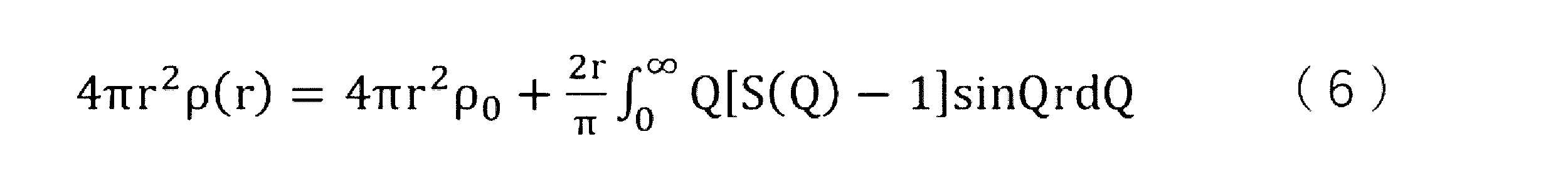
なお、図3においては、第1ピークP1のピークトップは1.43Åに位置し、第2ピークP2のピークトップは2.40Åに位置する。
1.43Åの位置には、B(ホウ素)-O(酸素)の原子間距離に帰属されるピークが存在する。また、2.40Åの位置には、B(ホウ素)-B(ホウ素)の原子間距離に帰属されるピークが存在する。つまり、上記2つのピーク(第1ピーク及び第2ピーク)が観測されるということは、上記2つの原子間距離に対応する周期構造が、固体電解質(I)中に存在することを意味する。
メカニカルミリング処理とは、試料を、機械的エネルギーを付与しながら粉砕する処理である。メカニカルミリング処理としては、例えば、ボールミル、振動ミル、ターボミル、及び、ディスクミルが挙げられ、生産性よく非晶状態の固体電解質(I)を得る点から、ボールミルが好ましい。ボールミルとしては、例えば、振動ボールミル、回転ボールミル、及び、遊星型ボールミルが挙げられ、遊星型ボールミルがより好ましい。
工程1A:リチウム塩の存在下で、リチウム含有酸化物にメカニカルミリング処理を施す工程
工程2A:工程1Aで得られた生成物と水とを混合する工程
工程3A:工程2Aで得られた分散液から水を除去して固体電解質(I)を得る工程
工程1Aで得られた生成物と水とを混合する方法は特に制限されず、一括で混合してもよいし、工程1Aで得られた生成物に段階的に水を加えて混合してもよい。混合する際には、必要に応じて、超音波処理を施してもよい。超音波処理の時間は特に制限されず、例えば、10分~5時間とすることができる。
工程1B:リチウム含有酸化物にメカニカルミリング処理を施す工程
工程2B:工程1Bで得られた生成物と水とリチウム塩とを混合する工程
工程3B:工程2Bで得られた分散液から水を除去して、固体電解質(I)を得る工程
工程2Bの手順は特に制限されず、工程1Bで得られた生成物と水とリチウム塩とを一括して混合する方法(方法1)であってもよいし、工程1Bで得られた生成物と水とを混合して分散液を調製した後、得られた分散液とリチウム塩とを混合する方法(方法2)であってもよいし、工程1Bで得られた生成物と水とを混合して分散液1を作製し、リチウム塩と水とを混合して溶液2を作製し、分散液1と溶液2とを混合する方法(方法3)であってもよい。工程1Bで得られた生成物と水とを混合する際には、超音波処理などの分散処理を適宜実施してもよい。
方法2においては、工程1Bで得られた生成物と水とを混合した分散液とリチウム塩とを混合する際に、リチウム塩が多すぎると、得られる液がゲル化しやすく、リチウム塩の混合量が制約される。それに対して、方法3では、工程1Bで得られた生成物とリチウム塩とを等モル量程度混合しても、液のゲル化が生じにくく、リチウム塩の混合量をより多くすることができる。この観点で、方法3が好ましい。
工程3Bと工程3Aの手順は同じである。
工程1C:リチウム含有酸化物にメカニカルミリング処理を施す工程
工程2C:工程1Cで得られた生成物と水とを混合する工程
工程3C:工程2Cで得られた分散液から水を除去して得られた生成物とリチウム塩とを混合して固体電解質(I)を得る工程
工程2Cと工程2Aの手順は同じである。
工程3Cは、工程2Cで得られた分散液から水を除去して得られた生成物とリチウム塩とを混合している点で、工程3A及び3Bと異なる。
工程3Cにおいて、リチウム塩の使用量は特に制限されず、本発明で規定する固体電解質(I)が得られるように適宜に調整される。
工程2Cで得られた分散液から水を除去して得られた生成物とリチウム塩との混合方法は特に制限されず、リチウム塩を水に溶解させた溶液を上記生成物に含浸させて、両者を混合する方法であってもよい。
本発明に用いる固体電解質(I)は、上記の通り、非晶状態の固体電解質であり、この固体電解質(I)中、リチウム含有酸化物の含有量に対して、リチウム塩の含有量の比の値がモル比で0.001~1.5であり、水の含有量の比の値がモル比で1~12である。
固体電解質(I)中のリチウム含有酸化物の含有量に対するリチウム塩の含有量の比の値は、モル比で0.001~1.2が好ましく、0.01~1.2がより好ましく、0.1~1.2がさらに好ましく、0.5~1.2が特に好ましい。
また、固体電解質(I)中のリチウム含有酸化物の含有量に対する水の含有量の比の値は、モル比で2~12がより好ましく、3~11がさらに好ましい。また、このモル比は2~10であることも好ましく、2~8であることも好ましく、2~7であることも好ましく、3~7であることも好ましい。
固体電解質(I)中のリチウム含有酸化物、リチウム塩、及び水のモル量は、元素分析に基づき決定することができる。また、水のモル量はカールフィッシャー法などにより決定することもできる。
また、固体電解質(I)中の水の含有量は、通常は5質量%以上であり、10質量%以上であることも好ましく、15質量%以上であることも好ましい。したがって、固体電解質(I)中の水の含有量は、5~50質量%が好ましく、5~45質量%がより好ましく、10~40質量%がさらに好ましく、10~35質量%がさらに好ましく、10~30質量%であることも好ましく、15~30質量%であることも好ましく、15~25質量%であることも好ましい。
固体電解質(I)中のリチウム含有酸化物の含有量は20~80質量%が好ましく、20~75質量%がより好ましく、25~70質量%がさらに好ましい。
また、固体電解質(I)中のリチウム塩の含有量は、0.5~60質量%が好ましく、1.0~55質量%がより好ましく、2.0~50質量%がさらに好ましく、5.0~50質量%であることも好ましい。
固体電解質(I)を構成するリチウム含有酸化物は、上記の通り、Li、B及びOを含む。
上記リチウム含有酸化物は、Li2+xB4+yO7+z(-0.3<x<0.3、-0.3<y<0.3、-0.3<z<0.3)で表される化合物が好ましい。つまり、Bのモル量を4.00として、Liのモル量を表したとき、Liのモル量は1.58~2.49(すなわち、1.7×4/4.3~2.3×4/3.7)であり、Oのモル量は6.23~7.89(すなわち、6.7×4/4.3~7.3×4/3.7)であることが好ましい。言い換えると、Bの含有モル量を4.00としたとき、Liの含有モル量の相対値が1.58~2.49であり、Oのモル量は6.23~7.89であることが好ましい。このようなリチウム含有酸化物として、典型的には四ホウ酸リチウム(Li2B4O7)が挙げられる。
また、上記リチウム含有酸化物は、Li1+xB3+yO5+z(-0.3<x<0.3、-0.3<y<0.3、-0.3<z<0.3)で表される化合物も好ましい。このようなリチウム含有酸化物として、典型的には三ホウ酸リチウム(LiB3O5)が挙げられる。
また、上記リチウム含有酸化物は、Li3+xB11+yO18+z(-0.3<x<0.3、-0.3<y<0.3、-0.3<z<0.3)で表される化合物も好ましい。このようなリチウム含有酸化物として、典型的にはLi3B11O18が挙げられる。
また、上記リチウム含有酸化物は、Li3+xB7+yO12+z(-0.3<x<0.3、-0.3<y<0.3、-0.3<z<0.3)で表される化合物も好ましい。このようなリチウム含有酸化物として、典型的にはLi3B7O12が挙げられる。
したがって、上記リチウム含有酸化物は、上記Li2+xB4+yO7+z、上記Li1+xB3+yO5+z、Li3+xB11+yO18+z、及びLi3+xB7+yO12+zの少なくとも1種であることが好ましい。
また、上記のリチウム含有酸化物に代えて、あるいは上記のリチウム含有酸化物とともに、リチウム含有酸化物としてLiBO5、Li2B7O12、LiB2O3(OH)H2O、及び、Li4B8O13(OH)2(H2O)3などの少なくとも1種を用いることもできる。
固体電解質(I)中において、リチウム含有酸化物は非晶状態にある。すなわち、固体電解質(I)が上述した非晶状態になるように、固体電解質(I)中においてリチウム含有酸化物も、所望の非晶状態にある。
なかでも、リチウム含有酸化物は、非晶状態の四ホウ酸リチウムであることが好ましい。
本発明に用いる固体電解質(I)を構成するリチウム塩は特に制限されず、Li+と陰イオンとから構成される塩で挙げられ、Li+と有機陰イオンから構成される塩が好ましく、Li+と、ハロゲン原子を有する有機陰イオンから構成される塩がより好ましい。
本発明に用いる固体電解質(I)を構成するリチウム塩は、周期律表第3族元素、周期律表第4族元素、周期律表第13族元素、周期律表第14族元素、周期律表第15族元素、周期律表第16族元素、周期律表第17族元素、および、Hからなる群から選択される特定元素を2種以上含むことが好ましい。
本発明に用いる固体電解質(I)を構成するリチウム塩としては、例えば、式(1)で表される化合物が好ましい。
式(1) LiN(Rf1SO2)(Rf2SO2)
Rf1及びRf2は、それぞれ独立に、ハロゲン原子又はパーフルオロアルキル基を示す。
Rf1及びRf2がパーフルオロアルキル基である場合において、パーフルオロアルキル基中の炭素数は特に制限されない。
Rf1及びRf2は、ハロゲン原子又は炭素数1~6のパーフルオロアルキル基であることが好ましく、ハロゲン原子又は炭素数1~2のパーフルオロアルキル基であることがより好ましく、ハロゲン原子であることがさらに好ましい。末端基の体積が増大すると立体障害が大きくなり、イオン伝導を阻害する要因となるため、Rf1及びRf2がパーフルオロアルキル基である場合、炭素数が少ないほうが好ましい。
なかでも、LiPF6、LiBF4、LiAsF6、LiSbF6、LiClO4、Li(Rf1SO2)、LiN(Rf1SO2)2、LiN(FSO2)2、又は、LiN(Rf1SO2)(Rf2SO2)が好ましく、LiPF6、LiBF4、LiN(Rf1SO2)2、LiN(FSO2)2、又は、LiN(Rf1SO2)(Rf2SO2)がより好ましい。これらの例示では、Rf1及びRf2は、それぞれ独立に、パーフルオロアルキル基を示し、炭素数は1~6が好ましく、1~4がより好ましく、1又は2がさらに好ましい。また、リチウム塩としてLiNO3、及び1,1,2,2,3,3-ヘキサフルオロプロパン-1,3-ジスルホンイミドリチウムも好ましい。
固体電解質(I)について、その成分組成を、固体電解質(I)を構成する化合物を基準として説明した。続いて、固体電解質(I)を、好ましい元素組成の観点から説明する。すなわち、本発明の二次電池は一形態において、固体電解質(I)について、「リチウム含有酸化物」及び「リチウム塩」を特定事項として有さずに、元素組成によって、例えば次のように特定することができる。
本発明に用いる固体電解質(I)は、固体電解質(I)中のBのモル量を4.00とした場合に、Liのモル量が1.58~3.49(好ましくは、1.58~3.00、より好ましくは1.90~3.00、さらに好ましくは2.00~3.00)であることが好ましい。また、固体電解質(I)中のBのモル量を4.00とした場合に、Oのモル量が6.23~25.00(好ましくは、6.50~23.00、より好ましくは8.00~23.00、さらに好ましくは10.00~23.00、さらに好ましくは10.00~18.00)であることが好ましい。また、固体電解質(I)中のBのモル量を4.00とした場合に、B以外かつLi以外かつO以外の元素のモル量がそれぞれ0.001~10.00(好ましくは0.001~6.00、より好ましくは0.01~5.00)であることが好ましい。
元素分析によって算出される各元素の含有量より、Bのモル量を4.00としたときのLi、O、及び、他の元素のモル量を算出する。
周期律表第4族元素としては、Ti、Zr、Hf、及び、Rfが挙げられる。周期律表第15族元素としては、N、P、As、Sb、Bi、及び、Mcが挙げられる。周期律表第16族元素としては、S、Se、Te、Po、及び、Lvが挙げられる。周期律表第17族元素としては、F、Cl、Br、I、At、及び、Tsが挙げられる。
固体電解質(I)に含まれる元素(E)の種類は3種以上であってもよく、2~5種が好ましく、2~4種がより好ましい。
固体電解質(I)の第2実施態様は、F、S、N、P、及び、Cから選択される2種以上の元素(E)を含むことが好ましく、F、S、C、及び、Nから選択される2種以上の元素(E)を含むことがより好ましく、F、S、及び、Nの3種の元素(E)を含むことがさらに好ましい。
固体電解質(I)は、固体電解質(I)の固体7Li-NMR測定を20℃及び120℃で行い、得られるスペクトルから下記の方法で算出される半値全幅割合が、50%以下であることが好ましく、40%以下であることがより好ましく、35%以下であることがさらに好ましい。下限は特に制限されないが、10%以上の場合が多い。
上記の半値全幅割合は、固体電解質(I)の固体7Li-NMR測定を20℃及び120℃でそれぞれ行い、20℃での測定で得られるスペクトルおける、化学シフトが-100~+100ppmの範囲に現れるピークの半値全幅(半値全幅1)と、120℃での測定で得られるスペクトルにおける、化学シフトが-100~+100ppmの範囲に現れるピークの半値全幅(半値全幅2)とを求めた後、半値全幅1に対する半値全幅2の割合の百分率{(半値全幅2/半値全幅1)×100}を算出することにより、得られる。ピークの半値全幅(FWHM)は、ピークの高さ(H)の1/2地点(H/2)での幅(ppm)を意味する。
以下、上記特性について図4を用いて説明する。図4では、固体電解質(I)の固体7Li-NMR測定を20℃又は120℃で行った際に得られるスペクトルの一例を示す。図4中の下側に示す実線のスペクトルが固体7Li-NMR測定を20℃で行った際に得られるスペクトルであり、図4中の上側に示す破線のスペクトルが固体7Li-NMR測定を120℃で行った際に得られるスペクトルである。
一般的に、固体7Li-NMR測定において、Li+の運動性が高い場合、得られるピークがよりシャープに得られる。図4に示す態様においては、20℃におけるスペクトルと120℃におけるスペクトルとを比較すると、120℃におけるスペクトルがよりシャープとなっている。つまり、図4に示す態様においては、Li欠陥などがあるために、Li+の運動性が高くなっていることを示す。このような固体電解質(I)は、上記のような欠陥構造に由来して、塑性変形しやすくなり、かつ、Li+のホッピング性に優れると考えられる。
なお、参考のために示すと、一般的な四ホウ酸リチウム結晶に関して、固体7Li-NMR測定を20℃又は120℃で行った際には、図5の下側に示す、実線で表される20℃で測定したスペクトルと、図5の上側に示す、破線で表される120℃で測定されるスペクトルとが略同じ形状となりやすい。つまり、四ホウ酸リチウム結晶においては、Li欠陥などがなく、結果として、弾性率が高く、塑性変形しづらい。
4mm HX CP-MASプローブを用い、シングルパルス法、90°パルス幅:3.2μs、観測周波数:155.546MHz、観測幅:1397.6ppm、繰り返し時間:15sec、積算:1回、MAS回転数:0Hzで測定する。
図6では、固体電解質(I)の固体7Li-NMR測定を20℃で行った際に得られるスペクトルの一例を示す。図6に示すように、固体電解質(I)は、-100~+100ppmの範囲にピーク(第1ピークに該当)が観測され、この第1ピークにおいては化学シフト0ppm付近に破線で囲ったように小さなピークが観測される。上述したように、Li+の運動性が高い場合、ピークがシャープに観測されるため、その影響が出ていると考えられる。
次に、第1ピークを波形分離したものを図7に示す。図7に示すように、第1のピークは、実線で表される小さなピーク(第2ピークに該当)と、破線で表される大きなピークに波形分離される。上記第2ピークは、化学シフトが-3~3ppmの範囲に現れ、半値全幅5ppm以下のピークである。
固体電解質(I)は、図6で表される第1ピーク(波形分離前のピーク)の面積強度に対する、図7の実線で表される第2ピークの面積強度の割合{(第2ピークの面積強度/第1ピークの面積強度)×100}が上記範囲内であることが好ましい。
波形分離の方法としては、公知のソフトを使用する方法が挙げられ、ソフトとしては、例えば、WaveMetrics社のグラフ処理ソフトIgor Pro(イゴールプロ)が挙げられる。
固体電解質(I)は、固体電解質(I)のラマンスペクトルの600~850cm-1の波数領域で、最小二乗法による線形回帰分析を行って得られる決定係数が、0.9400以上であることが好ましく、0.9600以上であることがより好ましく、0.9800以上であることも好ましい。上限は特に制限されないが、通常は1.0000以下である。
まず、固体電解質(I)のラマンスペクトルを取得する。ラマンスペクトルの測定方法としては、ラマンイメージングを実施する。ラマンイメージングとは、ラマン分光法に顕微技術を組み合わせた顕微分光手法である。具体的には、試料上で励起光を走査させることによりラマン散乱光を含む測定光を検出し、測定光の強度に基づいて成分の分布などを可視化する手法である。
ラマンイメージングの測定条件としては、27℃、大気下で、励起光を532nm、対物レンズを100倍、マッピング方式の点走査、1μmステップ、1点当たりの露光時間を1秒、積算回数を1回、測定範囲を70μm×50μmの範囲とする。
また、ラマンスペクトルのデータに対して、主成分分析(PCA)処理を施して、ノイズを除去する。具体的には、主成分分析処理においては、自己相関係数0.6以上の成分を用いてスペクトルを再結合する。
固体電解質(I)においては、図8に示すように、600~850cm-1の波数領域においてピークが略観測されず、結果として、高い決定係数を示す。
なお、上記決定係数R2は、相関係数(ピアソンの積率相関係数)の二乗に該当する。より具体的には、本明細書において、決定係数R2は、以下の式によって算出される。式中、x1及びy1は、ラマンスペクトル中の波数と、その波数に対応したラマン強度とを表し、x2は波数の(相加)平均を、y2はラマン強度の(相加)平均を表す。
つまり、上記決定係数が0.9400以上であることは、固体電解質(I)に結晶構造がほとんど含まれていないことを示している。そのため、結果として、固体電解質(I)は塑性変形しやすい特性、及び、Li+のホッピング性が優れる特性を有すると考えられる。
固体電解質(I)は、赤外吸収スペクトルにおいて、800~1600cm-1の波数領域における最大吸収強度に対する、3000~3500cm-1の波数領域における最大吸収強度の比の値(3000~3500cm-1の波数領域における最大吸収強度/800~1600cm-1の波数領域における最大吸収強度)が、1/5以上(0.2以上)であることが好ましい。なかでも、上記比が3/10以上が好ましく、2/5以上がより好ましい。上限は特に制限されないが、1以下が好ましい。
赤外吸収スペクトルの3000~3500cm-1の波数領域にはOH伸縮振動モードが観察され、800~1600cm-1の波数領域にはB-O伸縮振動モードが観察される。固体電解質(I)は、OH伸縮振動モードに由来する吸収強度が強く観測され、多数のOH基や多量の水が含まれていることがわかる。このような固体電解質(I)では、リチウムイオンが移動しやすくなり、結果として、イオン伝導性が向上する傾向にある。
なお、800~1600cm-1の波数領域においては、リチウム塩由来の振動モードも観察され得る。
対物レンズ:32倍カセグレン式(NA0.65)、検出器:MCT-A、測定範囲:650~4000cm-1、分解能:4cm-1、試料セル:ダイヤモンドセルで測定する。
得られた赤外吸収スペクトルについて、大気の水とCO2由来の信号除去のために補正をかけ、さらに、バックグラウンドにオフセット補正をかけて吸収強度0とする。また、40℃で2時間真空乾燥させた後に大気下で測定を行う。
固体電解質(I)を800℃まで加熱した際における質量減少率が20~40質量%であることが好ましく、25~35質量%がより好ましい。上記加熱により生じる質量減少は、固体電解質(I)に含まれる少なくとも水分が除去されていると考えられる。固体電解質(I)がこのような水分を含有することにより、リチウムイオンの伝導性をより向上させることができる。
上記加熱処理では、25℃から800℃までの範囲で20℃/秒の昇温速度にて加熱する。質量減少量の測定には、公知の熱重量示差熱分析(TG-DTA)装置を用いることができる。上記質量減少率は、
{(25℃における質量-800℃における質量)/25℃における質量}×100
によって算出される。
質量減少率の測定に当たり、固体電解質(I)は事前に、40℃で2時間の真空乾燥に付される。また、質量減少率の測定は大気下で行う。
例えば、固体電解質層は有機ポリマーからなるバインダーを含むことができる。バインダーを構成する有機ポリマーは、粒子状であってもよいし、非粒子状であってもよい。バインダーを含むことにより、固体電解質層ないし電極層に割れ等が生じることを、より確実に防ぐことが可能になる。
また、固体電解質層は、固体電解質(I)以外の他の固体電解質を含んでもよい。他の固体電解質とは、その内部においてリチウムイオンを移動させることができる固体状の電解質を意味する。固体電解質としては、無機の固体電解質が好ましい。他の固体電解質としては、硫化物系固体電解質、酸化物系固体電解質、ハロゲン化物系固体電解質、及び、水素化物系固体電解質が挙げられる。安全性を考慮すると、酸化物系固体電解質、ハロゲン化物系固体電解質、及び、水素化物系固体電解質の少なくとも1種が好ましく、酸化物系固体電解質がより好ましい。
固体電解質層中、固体電解質(I)の含有量は、50質量%以上が好ましく、60質量%以上がより好ましく、70質量%以上がさらに好ましく、80質量%以上であることも好ましく、90質量%であることも好ましい。
正極層は、正極集電体と正極活物質層とから構成されるのが一般的であるが、正極集電体が正極活物質層としても機能する場合(換言すれば、正極活物質層が正極集電体としても機能する場合)には、正極集電体と正極活物質層の2層で構成されている必要はなく、単層構成であってもよい。また、正極活物質層は、通常は、正極活物質とともに固体電解質(好ましくは無機固体電解質)を含有するが、固体電解質を含有していなくてもよい。正極活物質層中の正極活物質の含有量は、50質量%以上が好ましく、60質量%以上がより好ましく、70質量%以上がさらに好ましく、80質量%以上であることも好ましく、90質量%であることも好ましい。
柔軟性と安全性の両立を高いレベルで実現する観点から、上述した固体電解質(I)を用いることが好ましい。こうすることで、固体電解質(I)が正極層に含まれる固体粒子のバインダーのようにも作用して、正極層に、より柔軟性を持たせることができる。
正極活物質は、可逆的にリチウムイオンを挿入及び/又は放出できるものが好ましい。正極活物質は特に制限されず、遷移金属酸化物が好ましく、遷移金属元素Ma(Co、Ni、Fe、Mn、Cu及びVから選択される1種以上の元素)を含む遷移金属酸化物がより好ましい。また、この遷移金属酸化物に元素Mb(リチウム以外の周期律表の第1(Ia)族の金属元素、第2(IIa)族の元素、Al、Ga、In、Ge、Sn、Pb、Sb、Bi、Si、P及びBなどの元素)を混合してもよい。混合量としては、遷移金属元素Maの量(100mol%)に対して0~30mol%が好ましい。Li/Maのモル比が0.3~2.2になるように混合して合成されたものが、より好ましい。
遷移金属酸化物の具体例としては、(MA)層状岩塩型構造を有する遷移金属酸化物、(MB)スピネル型構造を有する遷移金属酸化物、(MC)リチウム含有遷移金属リン酸化合物、(MD)リチウム含有遷移金属ハロゲン化リン酸化合物、及び、(ME)リチウム含有遷移金属ケイ酸化合物が挙げられる。なかでも、(MA)層状岩塩型構造を有する遷移金属酸化物が好ましく、LiCoO2又はLiNi1/3Co1/3Mn1/3O2がより好ましい。
焼成法によって得られた正極活物質は、水、酸性水溶液、アルカリ性水溶液、有機溶剤にて洗浄した後、使用してもよい。
正極層を構成する集電体は、電子伝導体である。また、正極集電体は、通常はフィルムシート状である。
正極集電体の構成材料としては、アルミニウム、アルミニウム合金、ステンレス鋼、ニッケル、及び、チタンが挙げられ、アルミニウム又はアルミニウム合金が好ましい。なお、正極集電体としては、アルミニウム又はステンレス鋼の表面にカーボン、ニッケル、チタン又は銀を処理させたもの(薄膜を形成したもの)も挙げられる。
また、本発明の二次電池を構成する正極集電体の厚さは特に制限されず、例えば、10~100μmとすることができ、10~50μmが好ましい。
負極層は、負極集電体と負極活物質層とから構成されるのが一般的であるが、負極集電体が負極活物質層としても機能する場合(換言すれば、負極活物質層が負極集電体としても機能する場合)には、負極集電体と負極活物質層の2層で構成されている必要はなく、単層構成であってもよい。また、負極活物質層は、通常は、負極活物質とともに固体電解質(好ましくは無機固体電解質)を含有するが、固体電解質を含有していなくてもよい。
負極活物質層中の負極活物質の含有量は、50質量%以上が好ましく、60質量%以上がより好ましく、70質量%以上がさらに好ましく、80質量%以上であることも好ましく、90質量%であることも好ましい。
柔軟性と安全性の両立を高いレベルで実現する観点から、上述した固体電解質(I)を用いることが好ましい。こうすることで、固体電解質(I)が負極層に含まれる固体粒子のバインダーのようにも作用して、負極層に、より柔軟性を持たせることができる。
負極活物質は、可逆的にリチウムイオンを挿入及び放出できるものが好ましい。負極活物質は特に制限されず、例えば、炭素質材料、金属又は半金属元素の酸化物、リチウム単体、リチウム合金、及び、リチウムと合金形成可能な負極活物質が挙げられる。
さらに、PAN系炭素繊維、セルロース系炭素繊維、ピッチ系炭素繊維、気相成長炭素繊維、脱水PVA(ポリビニルアルコール)系炭素繊維、リグニン炭素繊維、ガラス状炭素繊維及び活性炭素繊維などの各種炭素繊維類、メソフェーズ微小球体、グラファイトウィスカー、並びに、平板状の黒鉛も挙げられる。
これらの炭素質材料は、黒鉛化の程度により難黒鉛化炭素質材料(ハードカーボンともいう。)と黒鉛系炭素質材料とに分けることもできる。
また、炭素質材料は、特開昭62-022066号公報、特開平2-006856号公報、及び、特開平3-045473号公報に記載される面間隔、密度、又は、結晶子の大きさを有することが好ましい。炭素質材料は、単一の材料である必要はなく、特開平5-090844号公報に記載の天然黒鉛と人造黒鉛の混合物、及び、特開平6-004516号公報に記載の被覆層を有する黒鉛を用いることもできる。
炭素質材料としては、ハードカーボン又は黒鉛が好ましく、黒鉛がより好ましい。
これらの酸化物としては、非晶質酸化物が好ましく、金属元素と周期律表第16族の元素との反応生成物であるカルコゲナイドも好ましい。
本発明において、半金属元素とは、金属元素と非金属元素との中間の性質を示す元素をいい、通常、ホウ素、ケイ素、ゲルマニウム、ヒ素、アンチモン及びテルルの6元素を含み、さらにはセレン、ポロニウム及びアスタチンの3元素を含む。
また、非晶質とは、CuKα線を用いたX線回折法で、2θ値で20~40°の領域に頂点を有するブロードな散乱帯を有するものを意味し、結晶性の回折線を有してもよい。2θ値で40~70°に見られる結晶性の回折線のうち最も強い強度が、2θ値で20~40°に見られるブロードな散乱帯の頂点の回折線強度の100倍以下であるのが好ましく、5倍以下であるのがより好ましく、結晶性の回折線を有さないことがさらに好ましい。
非晶質酸化物及びカルコゲナイドとしては、Ga2O3、GeO、PbO、PbO2、Pb2O3、Pb2O4、Pb3O4、Sb2O3、Sb2O4、Sb2O8Bi2O3、Sb2O8Si2O3、Sb2O5、Bi2O3、Bi2O4、GeS、PbS、PbS2、Sb2S3又はSb2S5が好ましい。
Sn、Si、又は、Geを中心とする非晶質酸化物負極活物質に併せて用いることができる負極活物質としては、リチウムイオン又はリチウム金属を吸蔵及び/又は放出できる炭素質材料、リチウム単体、リチウム合金、又は、リチウムと合金化可能な負極活物質が好ましい。
リチウムを含む金属複合酸化物(リチウム複合金属酸化物)としては、例えば、酸化リチウムと、上記金属酸化物、上記金属複合酸化物又は上記カルコゲナイドとの複合酸化物が挙げられる。より具体的には、Li2SnO2が挙げられる。
負極活物質(例えば、金属酸化物)は、チタン元素を含むこと(チタン酸化物)も好ましい。具体的には、Li4Ti5O12(チタン酸リチウム[LTO])は、リチウムイオンの吸蔵放出時の体積変動が小さいことから急速充放電特性に優れ、電極の劣化が抑制され全固体リチウムイオン二次電池の寿命向上が可能となる点で好ましい。
一般的に、これらの負極活物質を含む負極(例えば、ケイ素元素含有活物質を含むSi負極、スズ元素を含む活物質を含むSn負極)は、炭素負極(黒鉛及びアセチレンブラックなど)に比べて、より多くのLiイオンを吸蔵できる。すなわち、単位質量あたりのLiイオンの吸蔵量が増加する。そのため、電池容量を大きくすることができる。その結果、バッテリー駆動時間を長くすることができるという利点がある。
スズ元素を有する負極活物質としては、例えば、Sn、SnO、SnO2、SnS、SnS2、及び、上記ケイ素元素及びスズ元素を含む活物質が挙げられる。
体積平均粒子径の測定は、以下の手順で行う。
負極活物質を、水(水に不安定な物質の場合はヘプタン)を用いて20mLサンプル瓶中で1質量%の分散液を希釈調製する。希釈後の分散液試料は、1kHzの超音波を10分間照射し、その直後に試験に使用する。この分散液試料を用い、レーザ回折/散乱式粒度分布測定装置を用いて、温度25℃で測定用石英セルを使用してデータ取り込みを50回行い、体積平均粒子径を得る。その他の詳細な条件などは必要によりJIS Z 8828:2013「粒子径解析-動的光散乱法」の記載を参照する。1水準につき5つの試料を作製しその平均値を採用する。
表面被覆剤としては、Ti、Nb、Ta、W、Zr、Al、Si又はLiを含む金属酸化物が挙げられる。具体的には、チタン酸スピネル、タンタル系酸化物、ニオブ系酸化物、及び、ニオブ酸リチウム系化合物が挙げられ、例えば、Li4Ti5O12、Li2Ti2O5、LiTaO3、LiNbO3、LiAlO2、Li2ZrO3、Li2WO4、Li2TiO3、Li2B4O7、Li3PO4、Li2MoO4、Li3BO3、LiBO2、Li2CO3、Li2SiO3、SiO2、TiO2、ZrO2、Al2O3、B2O3、及びLi3AlF6が挙げられる。
また、負極活物質を含む電極表面は硫黄又はリンで表面処理されていてもよい。
さらに、負極活物質の粒子表面は、上記表面被覆の前後において活性光線又は活性気体(例えば、プラズマ)により表面処理を施されていてもよい。
負極層を構成する集電体は、電子伝導体である。また、負極集電体は、通常はフィルムシート状である。
負極集電体の構成材料としては、アルミニウム、銅、銅合金、ステンレス鋼、ニッケル、及び、チタンが挙げられ、アルミニウム、銅、銅合金、又は、ステンレス鋼が好ましい。なお、負極集電体としては、アルミニウム、銅、銅合金又はステンレス鋼の表面にカーボン、ニッケル、チタン又は銀を処理させたものも挙げられる。
また、本発明の二次電池を構成する負極集電体の厚さは特に制限されず、例えば、10~100μmとすることができ、10~50μmが好ましい。
導電助剤としては、一般的な導電助剤として知られているものを用いることができる。導電助剤としては、例えば、電子伝導性材料である、天然黒鉛、及び、人造黒鉛などの黒鉛類、アセチレンブラック、ケッチェンブラック、及び、ファーネスブラックなどのカーボンブラック類、ニードルコークスなどの無定形炭素、気相成長炭素繊維、及び、カーボンナノチューブなどの繊維状炭素、並びに、グラフェン、及び、フラーレンなどの炭素質材料が挙げられる。また、ポリアニリン、ポリピロール、ポリチオフェン、ポリアセチレン、及び、ポリフェニレン誘導体などの導電性高分子を用いてもよい。
上記導電助剤以外にも、金属粉又は金属繊維などの炭素原子を含有しない通常の導電助剤を用いてもよい。
導電助剤とは、電池を充放電した際にLiの挿入と放出が起きず、活物質として機能しないものをいう。従って、導電助剤の中でも、電池を充放電した際に活物質層中において活物質として機能しうるものは、導電助剤ではなく活物質に分類する。電池を充放電した際に活物質として機能するか否かは、一義的ではなく、活物質との組み合わせにより決定される。
本発明の二次電池は、少なくとも固体電解質層に固体電解質(I)を用いること以外は、通常の全固体二次電池の製造方法を参照して製造することができる。なお、得られる二次電池において、正極活物質層と固体電解質層と負極活物質層からなる積層体の含水率を本発明で規定するレベルまで低減するために、本発明の二次電池の製造では、固体電解質(I)を用いて正極活物質層と固体電解質層と負極活物質層を含む積層体を形成後、後述する真空乾燥処理等に付すことが好ましい。本発明の二次電池の製造方法について、好ましい実施形態を説明する。
本発明の二次電池は、上記の正極層と固体電解質層と負極層とをこの順に配した積層体を密封してなるものであることが好ましい。密封することにより、上記乾燥工程後、固体電解質層への水分の混入をより確実に防ぐことが可能となり、サイクル特性をより向上させることができる。密封の方法は特に制限されず、水分(大気)の混入を完全に遮断し、あるいは抑制できればよい。例えば、上記の正極層と固体電解質層と負極層とをこの順に配した積層体を格納する筐体(電池セル)の蓋を、Oリング等のガスケットを介して閉じることにより、積層体を封止する方法などが挙げられる。
また、各層の形成方法を逆にして、負極集電体上に、負極活物質層、固体電解質層及び正極活物質層を形成し、必要により全体を加圧処理に付して、全固体リチウムイオン二次電池を製造することもできる。
この場合、各層形成において、必要により不織布等の支持体を配して、各層を自立膜とすることが可能である。
なお、本発明の二次電池は、本発明で規定する二次電池が得られる限り、その製法は上記で説明したものに何ら限定されるものではない。
固体電解質(I)それ自体が柔らかく塑性変形し、バインダーのように作用して、固体粒子間ないし層間の結着性向上に寄与するために、有機ポリマーのようなバインダーを用いずに層形成をすることも可能である。
本発明の二次電池は、種々の用途に適用することができる。適用態様には特に制限はないが、例えば、電子機器に搭載する場合、ノートパソコン、ペン入力パソコン、モバイルパソコン、電子ブックプレーヤー、携帯電話、コードレスフォン子機、ページャー、ハンディーターミナル、携帯ファックス、携帯コピー、携帯プリンター、ヘッドフォンステレオ、ビデオムービー、液晶テレビ、ハンディークリーナー、ポータブルCD、ミニディスク、電気シェーバー、トランシーバー、電子手帳、電卓、メモリーカード、携帯テープレコーダー、ラジオ、及び、バックアップ電源が挙げられる。その他民生用として、自動車、電動車両、モーター、照明器具、玩具、ゲーム機器、ロードコンディショナー、時計、ストロボ、カメラ、及び、医療機器(ペースメーカー、補聴器、肩もみ機など)が挙げられる。さらに、各種軍需用、及び、宇宙用として用いることができる。また、太陽電池と組み合わせることもできる。
ボールミル(フリッチュ社製P-7)を用いて、粉末状のLi2B4O7結晶(LBO粉末)(レアメタリック社製)を、ポット:安定化ジルコニア(YSZ)(45mL)、粉砕用ボール:YSZ(平均粒子径:5mm、数:50個)、回転数:370rpm(revolutions per minute)、LBO粉末量:1g、雰囲気:大気、ボールミルの処理時間:100時間の条件にて、ボールミルして、微細化したリチウム含有酸化物(以下「リチウム含有酸化物の微細物」ともいう。)を得た。
得られたリチウム含有酸化物の微細物1gに、リチウム塩として0.05gのLiFSI(化学式:Li(FSO2)2N)を添加し(リチウム含有酸化物の微細物に対して5質量%である。)、さらに100時間ボールミルした。得られた粉末を、粉末濃度42質量%となるように水に添加し、30分間超音波分散させた。続いて、得られた分散液をガラスシャーレに移し、大気下にて、120℃で2時間乾燥させ、固体電解質のフィルムを得た。続いて、得られたフィルムを剥がして粉末状の固体電解質(I)-1を得た。
上記で得られた粉末状の固体電解質(I)-1を、27℃(室温)にて実効圧力220MPaで圧粉成形して、固体電解質の成形体(圧粉体1)を得た。圧粉体1の形状は、直径10mm、厚さ0.5~1mmの円柱状である。得られた圧粉体1のイオン伝導度を測定した結果、圧粉体1のイオン伝導度は、27℃で1.5×10⁻⁴S/cmであり、60℃で4.0×10-4S/cmであった。
解析の結果、X線全散乱測定から得られた還元二体分布関数G(r)において、rが1~5Åの範囲にて、ピークトップのG(r)が1.0超えを示し、ピークトップが1.43Åに位置する第1ピーク、及び、ピークトップのG(r)が1.0超えを示し、ピークトップが2.40Åに位置する第2ピークが確認された。
一方で、固体電解質(I)-1では、一般的な四ホウ酸リチウム結晶において観察されるB-O間距離及びB-B間距離に帰属されるピークは維持されていた。一般的な四ホウ酸リチウム結晶はBO4四面体とBO3三角形が1:1で存在する構造(ダイボレート構造)であり、固体電解質(I)-1ではその構造が維持されていると推定した。
また、固体7Li-NMR測定を20℃で行った際に得られるスペクトルにおいて-100~+100ppmの範囲に現れる第1ピークを波形分離した際に、化学シフトが-3~3ppmの範囲に半値全幅5ppm以下の第2ピークを有し、第1ピークの面積強度に対する第2ピークの面積強度の割合は4%であった。
固体電解質(I)-1を上述したように25℃から800℃まで加熱した際における質量減少率は29.8%であった。
参考例1で使用したリチウム含有酸化物の微細物1gを、この微細物の濃度が42質量%となるように水に添加し、30分間超音波分散させた。得られた分散液に、リチウム塩として0.05gのLiFSI(化学式:Li(FSO2)2N)を添加し(リチウム含有酸化物の微細物に対して5質量%である。)、さらに30分間超音波分散させた。
得られた分散液をガラスシャーレに移し、大気下にて、120℃で2時間乾燥させ、固体電解質のフィルムを得た。続いて、得られたフィルムを剥がして粉末状の固体電解質(I)-2を得た。固体電解質(I)-2について、参考例1と同様にして、大気下で各種評価を実施した。結果を下表にまとめて示す。
ボールミル(フリッチュ社製P-7)を用いて、粉末状のLi2B4O7(LBO粉末)(レアメタリック製)を、ポット:YSZ(45ml)、粉砕用ボール:YSZ(平均粒子径:5mm、重量:70g)、回転数:530rpm(revolutions per mi nute)、LBO粉末量:4.2g、雰囲気:大気、ボールミルの処理時間:100時間の条件にて、ボールミルして、リチウム含有酸化物の微細物を得た。
得られたリチウム含有酸化物の微細物を、この微細物の濃度が42質量%となるように水に添加し、60分間超音波処理して、分散液1を得た。
次に、リチウム塩として3.25gのLiFSI(化学式:Li(FSO2)2N)を、濃度87質量%となるように水に添加し、60分間超音波処理して、溶液2を得た。
得られた分散液1及び溶液2を混合し、マグネチックスターラーで60分間撹拌混合させた。続いて、得られた分散液を40℃、10Paで15時間、真空乾燥させて粉末状の固体電解質(I)-3を得た。得られた粉末を大気下で一定期間静置し、固体電解質(I)-3を用いて、参考例1と同様にして、大気下で各種評価を実施した。結果を下表にまとめて示す。
参考例3における分散液1の調製と同様にして分散液3を得た。
次に、リチウム塩として2.32gのLiFSI(化学式:Li(FSO2)2N)を、濃度87質量%で水に添加し、60分間超音波処理して、溶液4を得た。
得られた分散液3及び溶液4を混合し、マグネチックスターラーで60分間、撹拌混合させた。続いて、得られた分散液を40℃、10Paで15時間、真空乾燥させて粉末状の固体電解質(I)-4を得た。得られた粉末を大気下で一定期間静置し、固体電解質(I)-4を用いて、参考例1と同様にして、大気下で各種評価を実施した。結果を下表にまとめて示す。
参考例3における分散液1の調製と同様にして分散液5を得た。
次に、リチウム塩として4.65gのLiFSI(化学式:Li(FSO2)2N)を、濃度87質量%で水に添加し、60分間超音波処理して、溶液6を得た。
得られた分散液5及び溶液6を混合し、マグネチックスターラーで60分間、撹拌混合させた。続いて、得られた分散液を40℃、10Paで15時間、真空乾燥させて粉末状の固体電解質(I)-5を得た。得られた粉末を速やかに、参考例1と同様にして、大気下で各種評価を実施した。結果を下表にまとめて示す。
参考例3における分散液1の調製と同様にして分散液7を得た。
次に、リチウム塩として7.13gのLiTFSI(化学式:Li(F3CSO2)2N)を、濃度87質量%で水に添加し、60分間超音波処理して、溶液8を得た。
得られた分散液7及び溶液8を混合し、マグネチックスターラーで60分間撹拌混合させた。続いて、得られた分散液を40℃、10Paで15時間、真空乾燥させて粉末状の固体電解質(I)-6を得た。得られた粉末を大気下で一定期間静置し、固体電解質(I)-6を用いて、参考例1と同様にして、大気下で各種評価を実施した。結果を下表にまとめて示す。
なお、参考例6において、下記表1に示す炭素量は、リチウム塩中の各原子量を考慮して硫黄の分析質量から見積もった。
参考例1で使用したLBO粉末(ボールミルしていない粉末状のLi2B4O7結晶)について元素分析を行った結果、得られたLBO粉末の組成は、Li1.96B4.00O6.80であった。LBO粉末を27℃(室温)にて実効圧力220MPaで圧粉成形して、比較用の圧粉体C1を得た。得られた圧粉体C1のイオン伝導度は検出できなかった。
また、参考例1と同様にして、LBO粉末を用いてX線全散乱測定を行い、還元二体分布関数G(r)を得た。図10に、LBO粉末から得られた還元二体分布関数G(r)を示す。
解析の結果、LBO粉末のX線全散乱測定から得られた還元二体分布関数G(r)においては、ピークトップが1.40Åに位置する第1ピーク(B-O近接に対応)、ピークトップが2.40Åに位置する第2ピーク(BB近接に対応)が存在し、第1ピーク及び第2ピークのピークトップのG(r)は1.0以上であった(図10参照)。また、その他に、ピークトップが3.65Å、5.22Å、5.51Å、及び、8.54Åに位置するピークが存在し、それぞれのピークのピークトップのG(r)の絶対値は1.0を明らかに超えていた(図10参照)。
また、LBO粉末について、X線回折測定を上述の通りに行った。測定条件は、0.01°/ステップ、3°/minとした。図11に、比較参考例1のLBO粉末のX線回折パターンを示す。図11に示すように、比較参考例1で用いたLBO粉末は複数の幅の小さいピークが観測された。より具体的には、2θ値で21.78°の位置に(1,1,2)面に相当する最も強いピークが見られた。その他の主な回折ピークとして、25.54°の位置に(2,0,2)面に相当するピーク、33.58°の位置に(2,1,3)面に相当するピーク、34.62°の位置に(3,1,2)面に相当するピークが発現し、これら3つのピークの強度はほぼ同等であった。これらのピークは結晶成分に由来するものである。
参考例1で調製したリチウム含有酸化物の微細物(粉末状のLi2B4O7結晶をボールミルしたもの)に対して元素分析を行った結果、リチウム含有酸化物の微細物の組成は、Li1.94B4.00O6.80であった。
次いで、上記リチウム含有酸化物の微細物を、27℃(室温)にて実効圧力220MPaで圧粉成形して、参考用の圧粉体(圧粉体R1)を得た。得られた圧粉体R1のイオン伝導度は、27℃で7.5×10⁻⁹S/cmであり、60℃で7.5×10-8S/cmであった。
なお、下表に示す参考例1~4、及び、後述の参考例9~12においては、第1ピークのピークトップのG(r)の値は1.2以上であった。
また、上記還元二体分布関数G(r)において、rが5Å超10Å以下の範囲においてG(r)の絶対値が1.0未満を示す場合には、下表の「長距離G(r)」欄を「A」とし、G(r)の絶対値が1.0未満を満たさない場合を「B」とした。
また、上述したCuKα線を使用したX線回折測定の結果、上記のX線回折特性を満たす場合を「A」とし、満たさない場合を「B」とした。なお、下表に示す参考例1~6、及び、後述の参考例7~13においては、X線回折パターンにおいて、第1ピーク、第2ピーク、第3ピーク及び第4ピークがいずれも存在しないか、又は、第1ピーク、第2ピーク、第3ピーク及び第4ピークのうち少なくとも1つのピークの強度比が2.0以下であった。
<面積強度の割合の基準>
A:面積強度の割合が15%以上である場合
B:面積強度の割合が0.5%以上15%未満の場合
C:面積強度の割合が0.5%未満の場合
下表中、「-」は、測定値を示していないことを意味する。


参考例3で得られた固体電解質(I)-3の圧粉体(ペレット)(10mmφ、0.9mmt)を、60MPa拘束下、27℃で真空乾燥させ、真空乾燥時間に対する、圧力変化及びイオン伝導度を調べた。なお、圧粉体の作製方法、及び、イオン伝導度評価は、In電極をTi電極に変更した以外は、上述の通りである。結果を表3に示す。

上記参考例3における分散液1の調製と同様にして、リチウム含有酸化物の微細物の濃度が42質量%である分散液9を得た。
次に、リチウム塩として7.12gのLiTFSI(化学式:Li(F3CSO2)2Nを、濃度87質量%となるように水に添加し、60分間超音波処理して、溶液10を得た。
得られた分散液9及び溶液10を混合し、マグネチックスターラーで60分間撹拌混合させた。続いて、得られた分散液を40℃、10Paで15時間、真空乾燥させて粉末状の固体電解質(I)-7を得た。得られた粉末を大気下で一定期間静置し、固体電解質(I)-7を用いて、参考例1と同様にして、大気下で各種評価を実施した。結果を下表にまとめて示す。
得られる固体電解質(I)中における水及びLiTFSIの含有量が下表に記載の量になるように変更したこと以外は、参考例7と同様にして固体電解質(I)-8を得て、参考例1と同様にして、大気下で各種評価を実施した。結果を下表にまとめて示す。
LiTFSIをLiFSIに変更し、得られる固体電解質(I)中における水及びLiFSIの含有量が下表に記載の量になるように変更したこと以外は、参考例7と同様にして固体電解質(I)-9~(I)-13を得て、参考例1と同様にして、大気下で各種評価を実施した。結果を下表にまとめて示す。但し、参考例13は、真空乾燥させて得られた粉末を速やかに大気下で評価を実施した。
各元素の分析は、リチウム及びホウ素をICP-OESで、フッ素及び硫黄を燃焼イオンクロマトグラフィー(燃焼IC)で定量分析し、Nに関しては、Li塩中の各原子量を考慮して硫黄の分析質量から見積もり、Oに関しては、O以外の元素の分析質量を足し合わせ、固体電解質全量からの差分として算出した。なお、参考例7及び8において、炭素量は、リチウム塩中の各原子量を考慮して硫黄の分析質量から見積もった。固体電解質中のリチウム含有酸化物の微細物とリチウム塩とのモル比は、リチウム含有酸化物の微細物中にしかない元素(例えばB)とリチウム塩中にしかない元素のモル比から算出した。また、リチウム含有酸化物の微細物と水とのモル比は、固体電解質中のOのモル比からリチウム含有酸化物の微細物、リチウム塩に含まれるOのモル比を減算して、水に由来するOのモル量を算出して、得られた水由来のOのモル量とリチウム含有酸化物の微細物のモル量とを用いて算出した。
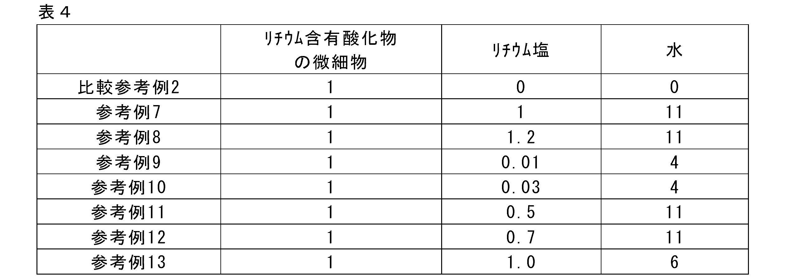
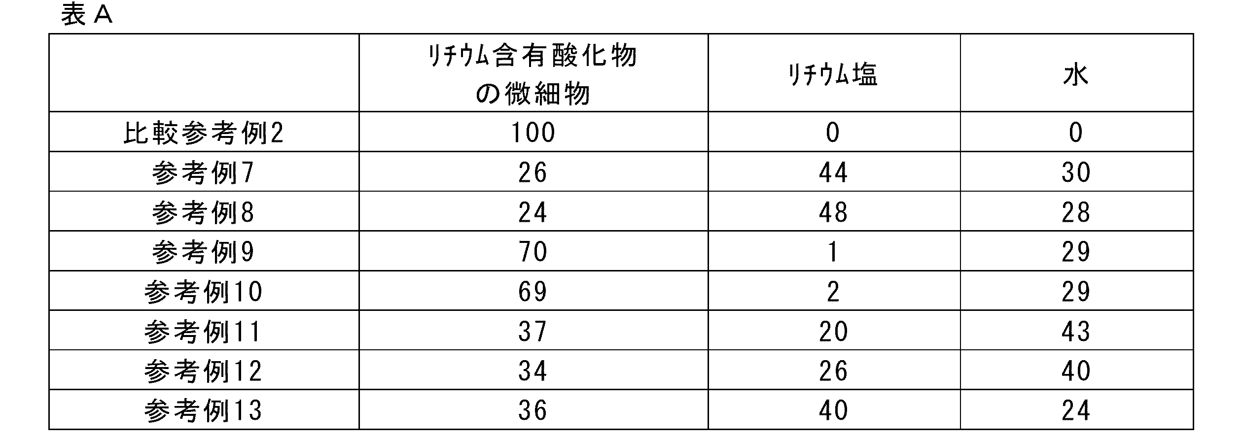
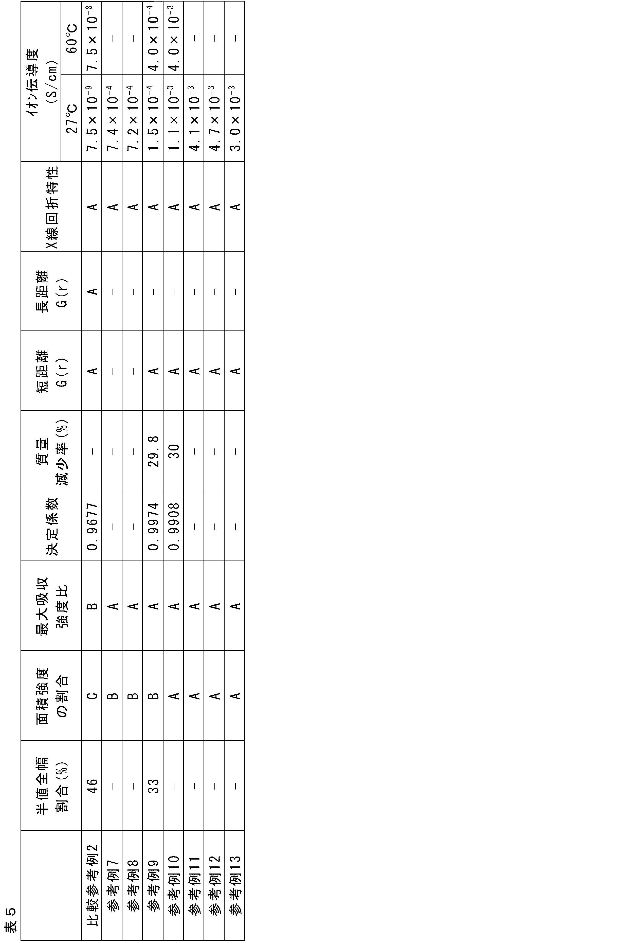
<リチウム含有酸化物の微細物の調製>
粉末状のLi2B4O7結晶(LBO粉末)(レアメタリック製)45gと、ジルコニアビーズ770gと、水3mLとを、500mLジルコニアポットに入れ、テフロンリングとジルコニア製の蓋で封止した。300rpmで45時間、遊星ボールミリング装置でLBO粉末を粉砕し、リチウム含有酸化物の微細物を得た。
上記のリチウム含有酸化物の微細物を10gと、水15gと、LiFSIの11gとをビーカー中で混合して、超音波洗浄機を用いて30分間超音波処理して分散液を得た。この分散液をさらにマグネチックスターラーで30分間撹拌し、固体電解質スラリー1を得た。
この固体電解質スラリー1を40℃、20Paで15時間真空乾燥して粉末を得た。得られた粉末をデシケータ(5%)で数日保管した後、大気下で分析したところ、上述したX線回折特性を有しており、非晶状態であることを確認した。また、上述した方法でイオン伝導度を測定したところ、4.5×10⁻³S/cmであった。また、リチウム含有酸化物の含有量に対して、LiFSIの含有量の比の値がモル比で1であり、水の含有量の比の値がモル比で9であった。元素組成(モル比)については、およそ次の通りであった。Li:B:O:F:S:N=3:4:20:2:2:1。
上記の固体電解質スラリー1の5.2gに、正極活物質LiCoO2を5.0gと、導電助剤としてカーボンナノチューブ(CNT)の6質量%水分散液(KJ特殊紙株式会社製)4.8gを加え、マグネチックスターラーで30分攪拌して、正極スラリー1を得た。
上記の固体電解質スラリー1の7.6gに、負極活物質TiNb2O7を5.0gと、導電助剤としてCNTの6質量%水分散液(KJ特殊紙株式会社製)9.8gを加え、マグネチックスターラーで30分攪拌して、負極スラリー1を得た。
上記の正極スラリー1を、卓上塗工機を用いて、アプリケーターギャップ100μm、塗工速度30mm/sで、50μm厚のA4サイズAl箔上に塗布した。1時間、室温で放置後、上記の固体電解質スラリー1を、卓上塗工機を用いて、アプリケーターギャップ200μm、塗工速度90mm/sで、正極スラリー塗膜上に重層塗布した。重層塗布膜を、相対湿度5%以下のデシケーター内に12時間保管して乾燥し、ハンドパンチで10mm径に打ち抜いて正極側積層体(固体電解質層/正極活物質層/Al集電体)を得た。なお、固体電解質層の厚さはおよそ60μmであった。
上記の負極スラリー1を、卓上塗工機を用いて、アプリケーターギャップ200μm、塗工速度30mm/sで、50μm厚のA4サイズAl箔上に塗布した。1時間、室温で放置後、上記の固体電解質スラリー1を、卓上塗工機を用いて、アプリケーターギャップ300μm、塗工速度90mm/sで、負極スラリー塗膜上に重層塗布した。重層塗布膜を、相対湿度5%以下のデシケーター内に12時間保管して乾燥し、ハンドパンチで10mm径に打ち抜いて負極側積層体(固体電解質層/負極物質層/Al集電体)を得た。なお、固体電解質層の厚さはおよそ60μmであった。
(実施例1)
上記の負極側積層体を、固体電解質層側を上に向けて、全固体電池評価セル(KP-SolidCell、宝泉株式会社製)の10mm径SUS(ステンレス鋼)台の上に置いた。この固体電解質層の上に、上記の正極側積層体を、固体電解質層側を下に向けて置いた。こうして正極側積層体/負極側積層体の構造の積層体(この積層体をセルと呼ぶ)を得た。
次いで、セルの正極集電体側から、内径10.2mmのテフロン管をはめ込み、テフロン管の上部の穴から10mm径、2mm厚の研磨Ti板を入れて、正極積層体の上に研磨Ti板を重ねた。さらに10mm径、高さ2cmのTi棒を研磨Ti板に上に置いた。
次いで、KP-SolidCellの上部筐体をはめ込んでダブルOリングと4点ボルトと蝶ナットで封止した。KP-SolidCellの上部に敷設されている拘束圧印加機構にて、5Nmのトルク(30MPa相当)で上下からセルを拘束した。
次いで、KP-SolidCellを開放してセルを取り出し、拘束圧印加で染み出した余分な液状成分を拭き取った。次いで、上記と同様にしてKP-SolidCellにセルをセットして上下からセルを拘束した。
次いで、上部の蓋を開放した状態で、KP-SolidCellごと2時間の凍結真空乾燥処理(10Pa、40℃)に付して、セル内部の水分を充分に除去した。真空乾燥機からKP-SolidCellを取り出し後、上部の蓋を、ダブルOリングを介して閉めて封止した。40時間放置した後、実施例1の電池とした。
実施例1の電池の製造において、Ti棒を研磨Ti板に上に置いた後にKP-SolidCellの空洞内に配するシリカゲル(富士フイルム和光純薬製、中粒状(青色))量(粒数)、凍結真空乾燥処理における真空乾燥処理時間を下表の通りとして、実施例1と同様にして電池を得た。
上記で得た電池に対し、拘束圧(30MPa)を印加し、27℃の温度条件下、東陽テクニカ製580-NOHFRを用いて、以下の条件で充電及び放電を繰り返し行った。
充電は、電池電圧が2.8Vになるまで一定の電流値Iβで行い、2.8Vになった後は電圧を一定(2.8V)にして、電流値が2.4Cレートになるまで行った。
充電後、回路を開放して10分間放置後、一定の電流値Iβで、電池電圧が1.5Vになるまで放電を行った。
ここまでの充電及び放電を1サイクルとした。
放電後、回路を開放して10分間放置後、次の充電に移り、同様の条件で充電及び放電を繰り返した。
なお、上記充電及び放電において、電流値Iβは、電池の初期化として、1サイクル目の充放電においては0.2Cに設定して行い、以降の充放電においては3Cに設定し、充放電サイクル試験を行った。
得られた電池をAr雰囲気下で解体してセルを取り出し、正極活物質層と前記固体電解質層と負極活物質層からなる積層体部分の5~10mg程度を試料として専用のバイアル瓶に封止した。合わせて、ブランクとしてAr雰囲気のみも専用のバイアル瓶に封止した。
カールフィッシャー測定用水分気化装置にバイアル瓶をセットし、100℃又は300℃の温度に加熱して水分を気化させた後、電量滴定式水分測定装置を用いてカールフィッシャー滴定法にて各試料の水分量を測定した。この水分量からブランクの水分量を差し引き、得られた値を試料量で除して、正極活物質層と前記固体電解質層と負極活物質層からなる積層体の含水率(質量%)とした。

2 負極活物質層
3 固体電解質層
4 正極活物質層
5 正極集電体
6 作動部位
10 全固体リチウムイオン二次電池
Claims (7)
- 正極層と固体電解質層と負極層とをこの順に配してなる全固体リチウムイオン二次電池であって、
前記固体電解質層は、Li、B及びOを含むリチウム含有酸化物とリチウム塩とを含む非晶状態の固体電解質を含み、該非晶状態の固体電解質中、前記リチウム含有酸化物の含有量に対して、前記リチウム塩の含有量の比の値がモル比で0.001~1.5であり、
正極活物質層と前記固体電解質層と負極活物質層からなる積層体の、100℃におけるカールフィッシャー滴定法に基づく含水率が7.0質量%以下であり、100℃及び300℃におけるカールフィッシャー滴定法に基づく含水率の差が0.1~5.0質量%である、全固体リチウムイオン二次電池。 - 正極層と固体電解質層と負極層とをこの順に配してなる全固体リチウムイオン二次電池であって、
前記固体電解質層は、Li、B及びOを含むリチウム含有酸化物とリチウム塩とを含む非晶状態の固体電解質を含み、該非晶状態の固体電解質中、前記リチウム含有酸化物の含有量に対して、前記リチウム塩の含有量の比の値がモル比で0.001~1.5であり、
正極活物質層と前記固体電解質層と負極活物質層からなる積層体が真空乾燥処理された積層体である、全固体リチウムイオン二次電池。 - 前記リチウム含有酸化物が、Li2+xB4+yO7+zを含む、請求項1又は2に記載の全固体リチウムイオン二次電池。
ただし、-0.3<x<0.3、-0.3<y<0.3、-0.3<z<0.3である。 - 前記リチウム塩が下記式(1)で表される、請求項1~3のいずれか1項に記載の全固体リチウムイオン二次電池。
式(1) LiN(Rf1SO2)(Rf2SO2)
式中、Rf1及びRf2は、それぞれ独立に、ハロゲン原子又はパーフルオロアルキル基を示す。 - 前記リチウム含有酸化物がメカニカルミリング処理に付されたものである、請求項1~4のいずれか1項に記載の全固体リチウムイオン二次電池。
- 前記全固体リチウムイオン二次電池が、前記の正極層と固体電解質層と負極層とをこの順に配した積層体を密封してなるものである、請求項1~5のいずれか1項に記載の全固体リチウムイオン二次電池。
- 前記全固体リチウムイオン二次電池の製造において、前記正極活物質層と前記固体電解質層と前記負極活物質層とを含む積層体を形成後、該積層体を真空乾燥処理に付すことを含む、請求項1~6のいずれか1項に記載の全固体リチウムイオン二次電池の製造方法。
Priority Applications (4)
| Application Number | Priority Date | Filing Date | Title |
|---|---|---|---|
| EP23816109.5A EP4535488A4 (en) | 2022-06-01 | 2023-05-31 | ALL-SOLID LITHIUM-ION SECONDARY BATTERY AND METHOD FOR MANUFACTURING ALL-SOLID LITHIUM-ION SECONDARY BATTERIES |
| CN202380039024.5A CN119174026A (zh) | 2022-06-01 | 2023-05-31 | 全固态锂离子二次电池及全固态锂离子二次电池的制造方法 |
| JP2024524911A JPWO2023234352A1 (ja) | 2022-06-01 | 2023-05-31 | |
| US18/963,552 US20250096317A1 (en) | 2022-06-01 | 2024-11-28 | All-solid-state lithium ion secondary battery and manufacturing method of all-solid-state lithium ion secondary battery |
Applications Claiming Priority (2)
| Application Number | Priority Date | Filing Date | Title |
|---|---|---|---|
| JP2022089965 | 2022-06-01 | ||
| JP2022-089965 | 2022-06-01 |
Related Child Applications (1)
| Application Number | Title | Priority Date | Filing Date |
|---|---|---|---|
| US18/963,552 Continuation US20250096317A1 (en) | 2022-06-01 | 2024-11-28 | All-solid-state lithium ion secondary battery and manufacturing method of all-solid-state lithium ion secondary battery |
Publications (1)
| Publication Number | Publication Date |
|---|---|
| WO2023234352A1 true WO2023234352A1 (ja) | 2023-12-07 |
Family
ID=89024906
Family Applications (1)
| Application Number | Title | Priority Date | Filing Date |
|---|---|---|---|
| PCT/JP2023/020288 Ceased WO2023234352A1 (ja) | 2022-06-01 | 2023-05-31 | 全固体リチウムイオン二次電池及び全固体リチウムイオン二次電池の製造方法 |
Country Status (5)
| Country | Link |
|---|---|
| US (1) | US20250096317A1 (ja) |
| EP (1) | EP4535488A4 (ja) |
| JP (1) | JPWO2023234352A1 (ja) |
| CN (1) | CN119174026A (ja) |
| WO (1) | WO2023234352A1 (ja) |
Cited By (1)
| Publication number | Priority date | Publication date | Assignee | Title |
|---|---|---|---|---|
| WO2025115485A1 (ja) * | 2023-11-29 | 2025-06-05 | 富士フイルム株式会社 | 固体電解質及び全固体リチウムイオン二次電池 |
Citations (10)
| Publication number | Priority date | Publication date | Assignee | Title |
|---|---|---|---|---|
| JPS6222066A (ja) | 1985-07-23 | 1987-01-30 | Wako Pure Chem Ind Ltd | ラテツクス凝集反応測定装置 |
| JPH026856A (ja) | 1988-06-27 | 1990-01-11 | Motonobu Shibata | 触媒担体およびその製造方法 |
| JPH0345473A (ja) | 1989-07-11 | 1991-02-27 | Toyoda Mach Works Ltd | 四輪操舵装置 |
| JPH0590844A (ja) | 1991-09-26 | 1993-04-09 | Toshiba Corp | 歪補償器 |
| JPH064516A (ja) | 1992-06-17 | 1994-01-14 | Toshiba Corp | 割当て決定支援方式 |
| JP2011054439A (ja) * | 2009-09-02 | 2011-03-17 | Nippon Zeon Co Ltd | 全固体二次電池 |
| JP2018052755A (ja) | 2016-09-26 | 2018-04-05 | 公立大学法人首都大学東京 | リチウムイオン伝導性材料 |
| JP2021044106A (ja) * | 2019-09-09 | 2021-03-18 | トヨタ自動車株式会社 | 全固体電池 |
| WO2021193204A1 (ja) | 2020-03-23 | 2021-09-30 | 富士フイルム株式会社 | 複合体、リチウムイオン伝導体、全固体リチウムイオン二次電池、全固体リチウムイオン二次電池用電極シート、四ホウ酸リチウム |
| JP2022089965A (ja) | 2015-08-17 | 2022-06-16 | フレキシタリック インベストメンツ インコーポレイテッド | ガスケット |
Family Cites Families (1)
| Publication number | Priority date | Publication date | Assignee | Title |
|---|---|---|---|---|
| JP6362371B2 (ja) * | 2014-03-18 | 2018-07-25 | 公立大学法人大阪府立大学 | 酸化物系固体電解質及びその用途 |
-
2023
- 2023-05-31 CN CN202380039024.5A patent/CN119174026A/zh active Pending
- 2023-05-31 EP EP23816109.5A patent/EP4535488A4/en active Pending
- 2023-05-31 JP JP2024524911A patent/JPWO2023234352A1/ja active Pending
- 2023-05-31 WO PCT/JP2023/020288 patent/WO2023234352A1/ja not_active Ceased
-
2024
- 2024-11-28 US US18/963,552 patent/US20250096317A1/en active Pending
Patent Citations (10)
| Publication number | Priority date | Publication date | Assignee | Title |
|---|---|---|---|---|
| JPS6222066A (ja) | 1985-07-23 | 1987-01-30 | Wako Pure Chem Ind Ltd | ラテツクス凝集反応測定装置 |
| JPH026856A (ja) | 1988-06-27 | 1990-01-11 | Motonobu Shibata | 触媒担体およびその製造方法 |
| JPH0345473A (ja) | 1989-07-11 | 1991-02-27 | Toyoda Mach Works Ltd | 四輪操舵装置 |
| JPH0590844A (ja) | 1991-09-26 | 1993-04-09 | Toshiba Corp | 歪補償器 |
| JPH064516A (ja) | 1992-06-17 | 1994-01-14 | Toshiba Corp | 割当て決定支援方式 |
| JP2011054439A (ja) * | 2009-09-02 | 2011-03-17 | Nippon Zeon Co Ltd | 全固体二次電池 |
| JP2022089965A (ja) | 2015-08-17 | 2022-06-16 | フレキシタリック インベストメンツ インコーポレイテッド | ガスケット |
| JP2018052755A (ja) | 2016-09-26 | 2018-04-05 | 公立大学法人首都大学東京 | リチウムイオン伝導性材料 |
| JP2021044106A (ja) * | 2019-09-09 | 2021-03-18 | トヨタ自動車株式会社 | 全固体電池 |
| WO2021193204A1 (ja) | 2020-03-23 | 2021-09-30 | 富士フイルム株式会社 | 複合体、リチウムイオン伝導体、全固体リチウムイオン二次電池、全固体リチウムイオン二次電池用電極シート、四ホウ酸リチウム |
Non-Patent Citations (1)
| Title |
|---|
| See also references of EP4535488A4 |
Cited By (1)
| Publication number | Priority date | Publication date | Assignee | Title |
|---|---|---|---|---|
| WO2025115485A1 (ja) * | 2023-11-29 | 2025-06-05 | 富士フイルム株式会社 | 固体電解質及び全固体リチウムイオン二次電池 |
Also Published As
| Publication number | Publication date |
|---|---|
| EP4535488A4 (en) | 2025-12-31 |
| JPWO2023234352A1 (ja) | 2023-12-07 |
| EP4535488A1 (en) | 2025-04-09 |
| CN119174026A (zh) | 2024-12-20 |
| US20250096317A1 (en) | 2025-03-20 |
Similar Documents
| Publication | Publication Date | Title |
|---|---|---|
| US11817548B2 (en) | All solid-state secondary battery, inorganic solid electrolyte particles, solid electrolyte composition, electrode sheet for battery, and method for manufacturing all solid-state secondary battery | |
| KR102884163B1 (ko) | 리튬계 고체 전해질, 무기 고체 전해질, 리튬계 고체 전해질의 제조 방법, 수식 정극 활물질, 수식 부극 활물질, 전고체 이차 전지, 전고체 이차 전지용 전극 시트, 고체 전해질 시트, 전고체 이차 전지용 전극 | |
| JP7377502B2 (ja) | 複合体、リチウムイオン伝導体、全固体リチウムイオン二次電池、全固体リチウムイオン二次電池用電極シート、四ホウ酸リチウム | |
| US20230327192A1 (en) | Oxide solid electrolyte, binder, solid electrolyte layer, active material, electrode, all-solid state secondary battery | |
| WO2019087750A1 (ja) | 活物質層形成用組成物及びその製造方法、並びに、全固体二次電池用電極シート及び全固体二次電池の製造方法 | |
| WO2023234351A1 (ja) | 全固体リチウムイオン二次電池及び全固体リチウムイオン二次電池の製造方法 | |
| US20250096244A1 (en) | Electrode composition for all-solid-state secondary battery, electrode sheet for all-solid-state secondary battery, all-solid-state secondary battery, and manufacturing method of electrode sheet for all-solid-state secondary battery, and manufacturing method of all-solid-state secondary battery | |
| US20250096317A1 (en) | All-solid-state lithium ion secondary battery and manufacturing method of all-solid-state lithium ion secondary battery | |
| US20250096318A1 (en) | Electrode composition for all-solid-state secondary battery, electrode sheet for all-solid-state secondary battery, all-solid-state secondary battery, and manufacturing method of electrode sheet for all-solid-state secondary battery, and manufacturing method of all-solid-state secondary battery | |
| US20250096316A1 (en) | Wound-type all-solid-state lithium ion secondary battery and manufacturing method of wound-type all-solid-state lithium ion secondary battery | |
| WO2023234209A1 (ja) | リチウム系固体電解質、リチウム系固体電解質の製造方法、修飾正極活物質、修飾負極活物質、全固体二次電池、全固体二次電池用電極シート、固体電解質シート、全固体二次電池用電極 | |
| WO2023234357A1 (ja) | 活物質の回収方法 | |
| JP7756967B2 (ja) | 全固体リチウムイオン二次電池及び全固体リチウムイオン二次電池の製造方法 | |
| CN116648797B (zh) | 锂系固体电解质、无机固体电解质、锂系固体电解质的制造方法、修饰正极活性物质、修饰负极活性物质、全固态二次电池、全固态二次电池用电极片、固体电解质片、全固态二次电池用电极 | |
| WO2025115485A1 (ja) | 固体電解質及び全固体リチウムイオン二次電池 | |
| CN116648797A (zh) | 锂系固体电解质、无机固体电解质、锂系固体电解质的制造方法、修饰正极活性物质、修饰负极活性物质、全固态二次电池、全固态二次电池用电极片、固体电解质片、全固态二次电池用电极 |
Legal Events
| Date | Code | Title | Description |
|---|---|---|---|
| 121 | Ep: the epo has been informed by wipo that ep was designated in this application |
Ref document number: 23816109 Country of ref document: EP Kind code of ref document: A1 |
|
| WWE | Wipo information: entry into national phase |
Ref document number: 2024524911 Country of ref document: JP |
|
| WWE | Wipo information: entry into national phase |
Ref document number: 2023816109 Country of ref document: EP |
|
| NENP | Non-entry into the national phase |
Ref country code: DE |
|
| ENP | Entry into the national phase |
Ref document number: 2023816109 Country of ref document: EP Effective date: 20250102 |
|
| WWP | Wipo information: published in national office |
Ref document number: 2023816109 Country of ref document: EP |